CN115070407B - Method for assembling and positioning array elements of auxiliary antenna array surface in large scale - Google Patents
Method for assembling and positioning array elements of auxiliary antenna array surface in large scale Download PDFInfo
- Publication number
- CN115070407B CN115070407B CN202210547717.2A CN202210547717A CN115070407B CN 115070407 B CN115070407 B CN 115070407B CN 202210547717 A CN202210547717 A CN 202210547717A CN 115070407 B CN115070407 B CN 115070407B
- Authority
- CN
- China
- Prior art keywords
- assembly
- image
- light source
- photothermal
- positioning
- Prior art date
- Legal status (The legal status is an assumption and is not a legal conclusion. Google has not performed a legal analysis and makes no representation as to the accuracy of the status listed.)
- Active
Links
Images


Classifications
-
- B—PERFORMING OPERATIONS; TRANSPORTING
- B23—MACHINE TOOLS; METAL-WORKING NOT OTHERWISE PROVIDED FOR
- B23P—METAL-WORKING NOT OTHERWISE PROVIDED FOR; COMBINED OPERATIONS; UNIVERSAL MACHINE TOOLS
- B23P21/00—Machines for assembling a multiplicity of different parts to compose units, with or without preceding or subsequent working of such parts, e.g. with programme control
-
- B—PERFORMING OPERATIONS; TRANSPORTING
- B23—MACHINE TOOLS; METAL-WORKING NOT OTHERWISE PROVIDED FOR
- B23P—METAL-WORKING NOT OTHERWISE PROVIDED FOR; COMBINED OPERATIONS; UNIVERSAL MACHINE TOOLS
- B23P19/00—Machines for simply fitting together or separating metal parts or objects, or metal and non-metal parts, whether or not involving some deformation; Tools or devices therefor so far as not provided for in other classes
Landscapes
- Engineering & Computer Science (AREA)
- Mechanical Engineering (AREA)
- Variable-Direction Aerials And Aerial Arrays (AREA)
Abstract
本发明公开的一种辅助天线阵面大规模阵元组装定位方法,能够显著提高材料利用率,生产效率,降低生产成本。本发明通过下述技术方案实现:首先,利用PCB基板或其它柔性基板制作成光热基板,每一个阵元安装孔一一对应一个石墨烯光源凸点和导引柱,感知控制系统利用组装导引柱伸出的长度作为焊锡环的装配指引,实现机械臂对焊锡环的自动组装;在光热基板的一端设置光热感应绑定头,并将阵元同轴装配在光热感应绑定头中,同时引导机械臂快速将焊锡环装入阵元接口内;石墨烯光源凸点利用电源、驱动模块实现石墨烯光源凸点的发光,并发热产生热量,石墨烯光源凸点发光、发热的位置与其天线阵面的安装孔位置一一对应,定位后,完成阵元的高精度组装。

The invention discloses a large-scale array element assembly and positioning method for an auxiliary antenna front, which can significantly improve material utilization rate, production efficiency, and reduce production cost. The present invention is realized through the following technical solutions: First, a photothermal substrate is made by using a PCB substrate or other flexible substrates, and each array element installation hole corresponds to a graphene light source bump and a guide column one by one, and the perception control system utilizes the assembly guide The protruding length of the lead post is used as the assembly guide of the solder ring to realize the automatic assembly of the solder ring by the robotic arm; a photothermal induction bonding head is set at one end of the photothermal substrate, and the array element is coaxially assembled on the photothermal induction bonding At the same time, guide the mechanical arm to quickly put the solder ring into the interface of the array element; the graphene light source bump uses the power supply and the drive module to realize the light emission of the graphene light source bump, and generates heat, and the graphene light source bump emits light and heat The position of the antenna corresponds to the position of the mounting hole of the antenna array. After positioning, the high-precision assembly of the array element is completed.
Description
技术领域technical field
本发明涉及一种大型相控阵雷达(Large-scalePhasedArrayRadar,LPAR)技术领域,尤其是具有3000多阵阵元组件雷达阵面连接块相控阵雷达组装辅助定位与检测技术。The present invention relates to a large-scale phased array radar (Large-scale Phased Array Radar, LPAR) technical field, especially has more than 3000 array element components radar array connection block phased array radar assembly auxiliary positioning and detection technology.
背景技术Background technique
有源相控阵雷达天线阵面体积庞大,高达数十米,T/R单元(收发组件)数以千计,是雷达的核心部分,其作用是实现相控阵天线的电性能。天线阵面内部安装有天线、馈线、T/R、电源、冷却等系统诸多设备,是整个雷达中结构最复杂的部分。天线阵面包括:雷达主天线、阵面馈电网络、询问机及二次雷达共用天线、高频箱、高频箱内电子设备、阵面环境控制系统等。雷达主天线安装有3000个天线单元,天线单元安装在高频箱外部,其余电子设备均安装在高频箱内部。天线有源阵面的高频箱内电子设备量大,包括了组件、阵面综合网络、接收(数字化接收通道、干扰分析通道和频率源)、波束形成与反干扰、信号处理、阵面冷却管网、阵面电源、二次雷达设备(行馈和收发分机)等多个分系统的设备。高频箱主要包括折弯板以及环梁有关高频箱。主要部件之间都采用焊接连接方式,材料为5A05。天线阵面主要承力为中块高频箱。阵面坐标系定义为X向为阵面水平方向、Y向为阵面竖直方向、Z向垂直于阵面。The active phased array radar antenna has a huge array, up to tens of meters, and thousands of T/R units (transmitting and receiving components). It is the core part of the radar, and its function is to realize the electrical performance of the phased array antenna. Antenna, feeder, T/R, power supply, cooling and other systems are installed inside the antenna array, which is the most complex part of the entire radar. The antenna array includes: radar main antenna, array feeder network, interrogator and secondary radar common antenna, high frequency box, electronic equipment in the high frequency box, front environment control system, etc. The main antenna of the radar is equipped with 3000 antenna units, the antenna unit is installed outside the high frequency box, and the rest of the electronic equipment is installed inside the high frequency box. The high-frequency box of the active front of the antenna has a large amount of electronic equipment, including components, front integrated network, reception (digital reception channel, interference analysis channel and frequency source), beam forming and anti-jamming, signal processing, and front cooling Equipment for multiple subsystems such as pipe network, front power supply, secondary radar equipment (line feed and transceiver extension). The high frequency box mainly includes the bent plate and the ring beam related high frequency box. The main components are connected by welding, and the material is 5A05. The main force of the antenna array is the medium-block high-frequency box. The front coordinate system is defined as the X direction is the front horizontal direction, the Y direction is the front vertical direction, and the Z direction is perpendicular to the front.
随着有源相控阵雷达的发展,雷达的机动性要求也越来越高,天线阵面的口径越来越大,阵元规模也越来越大。一部相控阵雷达像面基板上通常包含有成百上千个像阵面组件和,已从传统的9阵、16阵逐步发展到3000多阵,随着各类载机平台旺盛的需求,未来的相控阵天线的阵元规模甚至可能将提升到6000阵以上,如果采用人工方式组装和测试如此大规模的相控阵雷达天线,所需要花费的时间之长可见一斑,其中安装焊片、线阵导热片、面阵导热片和安装插座的步骤的工时时长相当大,以典型1000多阵为例,仅将焊片和阵元SMP插座组装完毕就需要至少8个小时的工时,还不包括物料准备环节、组装过程中操作人员的休息、调整时间以及组装出错后重新安装的时间,如此长的工时往往成为相控阵天线批产的瓶颈。With the development of active phased array radar, the mobility requirements of radar are getting higher and higher, the aperture of antenna array is getting bigger and bigger, and the scale of array elements is getting bigger and bigger. A phased array radar image surface substrate usually contains hundreds or thousands of image array components and has gradually developed from the traditional 9 arrays and 16 arrays to more than 3,000 arrays. With the strong demand of various aircraft platforms In the future, the array element size of the phased array antenna may even increase to more than 6,000 arrays. If such a large-scale phased array radar antenna is assembled and tested manually, it will take a long time. The working hours of the steps of sheet, linear array heat conduction sheet, area array heat conduction sheet and socket installation are quite long. Taking a typical example of more than 1,000 arrays, it takes at least 8 hours of work to complete the assembly of the solder sheet and the array element SMP socket. This does not include material preparation, operator rest during assembly, adjustment time, and reinstallation time after assembly errors. Such long working hours often become the bottleneck of mass production of phased array antennas.
有源相控阵雷达的每个天线阵元均采用独立的T/R模块,且每个组件都能发送和产生高频电磁能量。在功率、效率、波束控制、测量精确度等方面有较大优势,并且重量轻于无源相控阵。在大型相控阵雷达的所有结构件中,最重要的关键部件是反射面板,该面板是整个相控阵雷达结构的基准,同时也是相控阵雷达中最主要的承力结构件。大型地面相控阵雷达的设计要求和结构形式的相控阵雷达结构大,安装精度高,动态变形大,阵列设备多,天线阵面单元数多达上万个,施工条件有限。对结构单元的组合化、模块化,以及现场架设性能提出了高要求。不同的天线阵面安装结构形式对雷达装备的架设、阵面精度的控制带来了不同的影响。天线阵面结构是相控阵雷达大部分电子设备的载体,直接保证天线阵面及整部雷达的精度和可靠性,阵面布局、优化分析及试验验证又是天线阵面结构的关键技术。由于相控阵雷达天线阵面是相控阵雷达的关键设备,因此对工艺总体方案的确定提出了很高的要求。为防止焊接缺陷的产生必须进行焊前预热、焊后缓冷,为减少变形采用双面多层多道焊接工艺也必须配合大型吊装工具,操作困难,工序繁杂。质量低:由于焊缝缺陷严重,每条焊缝必须严格探伤,产品都必须经过数次修补才能勉强达到要求,焊接过程的反复加热使焊缝强度、塑性大大降低。目前大尺寸、大厚度铝合金板焊接多采用的MIG两面多层多道填充对接焊,存在多气孔、夹渣,变形大、残余应力大和效率低、高能耗等一系列问题。Each antenna element of the active phased array radar adopts an independent T/R module, and each component can transmit and generate high-frequency electromagnetic energy. It has great advantages in power, efficiency, beam control, measurement accuracy, etc., and is lighter than passive phased arrays. Among all the structural parts of large-scale phased array radar, the most important key component is the reflector panel, which is the benchmark of the entire phased array radar structure and is also the most important load-bearing structural part of phased array radar. Design requirements and structural form of large-scale ground phased array radar Phased array radar has a large structure, high installation accuracy, large dynamic deformation, many array devices, tens of thousands of antenna array elements, and limited construction conditions. High requirements are placed on the combination and modularization of the structural units, as well as on-site erection performance. Different antenna array installation structures have different effects on the erection of radar equipment and the control of array accuracy. The antenna array structure is the carrier of most of the electronic equipment of the phased array radar, which directly guarantees the accuracy and reliability of the antenna array and the whole radar. The array layout, optimization analysis and experimental verification are the key technologies of the antenna array structure. Since the antenna array of phased array radar is the key equipment of phased array radar, high requirements are put forward for the determination of the overall process plan. In order to prevent welding defects, it is necessary to preheat before welding and cool slowly after welding. To reduce deformation, the double-sided multi-layer multi-pass welding process must also be used with large lifting tools, which is difficult to operate and complicated. Low quality: due to serious weld defects, each weld must be strictly inspected, and the product must be repaired several times to barely meet the requirements. Repeated heating during the welding process greatly reduces the strength and plasticity of the weld. At present, the MIG two-sided multi-layer multi-pass filling butt welding is mostly used for welding large-size and large-thickness aluminum alloy plates, which has a series of problems such as many pores, slag inclusions, large deformation, large residual stress, low efficiency, and high energy consumption.
在相控阵雷达研制与生产过程中,相控阵天线组件的自动组装与测试技术越来越成为影响产品研制和生产进度及质量的关键性因素。自动化组装与测试,对提升生产效率、技术水平和产品质量,降低能源资源消耗,实现制造过程的智能化和绿色化发展具有重要意义。发展自动化组装与测试需要解决多个关键技术难题,诸如精密机构设计、高性能材料、环境智能感知、智能控制、高速网络通信、系统可靠性等;其中自动化组装与测试的环境感知和智能控制技术作为高适应性、高精度、智能化作业的根本保障,是智能制造装备研制要首先解决的技术难题。在工业4.0框架下,自动化组装与测试的感知和控制技术必须具备以下特点:In the development and production process of phased array radar, the automatic assembly and testing technology of phased array antenna components has increasingly become a key factor affecting the progress and quality of product development and production. Automated assembly and testing is of great significance to improving production efficiency, technical level and product quality, reducing energy and resource consumption, and realizing the intelligent and green development of the manufacturing process. The development of automated assembly and testing needs to solve several key technical problems, such as precision mechanism design, high-performance materials, environmental intelligent perception, intelligent control, high-speed network communication, system reliability, etc.; the environmental perception and intelligent control technology of automated assembly and testing As the fundamental guarantee of high adaptability, high precision and intelligent operation, it is the technical problem that must be solved first in the development of intelligent manufacturing equipment. Under the framework of Industry 4.0, the perception and control technology of automated assembly and testing must have the following characteristics:
实时性。装备感知和控制速度必须满足生产线上大规模作业的需求;real-time. The speed of equipment perception and control must meet the needs of large-scale operations on the production line;
高精度。环境感知准确率、特异性、分辨率要足够高,以保证加工作业精度;High precision. The accuracy, specificity, and resolution of environmental perception should be high enough to ensure the accuracy of processing operations;
无损感知。装备感知环节最好采用非接触检测方式,尽可能减少对现有生产线的改变。这其中,高精度定位与检测技术显得尤为重要,传统的技术途径中,为了实现自适应动态定位,需要结合相关图像处理技术提取目标点的特征,进行目标的识别和定位。目前,已有的很多高精度定位技术主要依靠定位工装、图像识别或视觉识别。定位工装成本低,但是在辅助提高定位精度能力方面有限;图像识别技术应用最广泛,但是容易受制于来料的一致性;视觉识别的精度高,但是最好能够配备辅助高精度定位工具,其定位能力会大幅度提升。Lossless perception. It is best to use non-contact detection in the equipment perception link to minimize changes to the existing production line. Among them, high-precision positioning and detection technology is particularly important. In the traditional technical approach, in order to achieve adaptive dynamic positioning, it is necessary to combine relevant image processing technology to extract the characteristics of the target point for target recognition and positioning. At present, many existing high-precision positioning technologies mainly rely on positioning tooling, image recognition or visual recognition. The cost of positioning tooling is low, but its ability to assist in improving positioning accuracy is limited; image recognition technology is the most widely used, but it is easily subject to the consistency of incoming materials; visual recognition has high accuracy, but it is best to be equipped with auxiliary high-precision positioning tools. The positioning ability will be greatly improved.
深度学习作为人工智能一个重要的分支,受到人们越来越多的关注,而目标检测这个计算机视觉的基础性研究领域也因为深度学习的快速发展焕发出了新的活力。目标检测即是在图像或者视频中找到目标物体的位置,并确定物体的类别。由于图像中目标的形态和大小不一,数量和位置不定,这使得目标检测一直是计算机视觉检测领域的难题之一。传统的目标检测采滑动窗口和图片缩放的方式,这种方式检测效率差,精度低,为了改善传统检测算法的弊端,将深度学习和目标检测相结合的方法应用而生。目标检测(ObjectDetection)是计算机视觉领域的基本任务之一,目标检测算法(如:R-CNN系列,YOLO算法,SSD算法等)可以实现端到端的检测和定位。传统的目标检测算法主要依赖于人工选取的特征来对物体进行检测。人工提取的特征对主要针对某些特定对象,比如有的特征适合做边缘检测,有的适合做纹理检测,不具有普遍性。目标检测算法从基于手工特征的传统算法转向了基于深度神经网络的检测技术。已有的基于深度学习的目标检测算法主要集中在两个方向:twostage算法如R-CNN系列和onestage算法如YOLO、SSD等。两者的主要区别在于twostage算法需要先生成proposal(一个有可能包含待检物体的预选框),然后进行细粒度的物体检测。而onestage算法会直接在网络中提取特征来预测物体分类和位置。以R-CNN系列为代表的wostge目标检测算法,这类算法要先产生候选区域,然后再对候选区域进行分类和边框位置的修正,但由于其输入图像经过剪裁和变形后会导致信息丢失和位置信息扭曲,从而影响识别精度,并且R-CNN需要对每张图片中的上千个变形后的区域反复调用CNN,所以特征计算非常耗时,速度较慢。另一种以SSD、YOLO等为代表的基于回归的one-stage目标检测算法,这类算法不需要产生候选区域直接对目标物体进行回归。由于YOLO在检测过程中仅选择置信度最高的边界框作为最终的输出,即每个网格最多只检测出一个物体,因此YOLO在检测紧邻群体目标或小目标时效果不佳。As an important branch of artificial intelligence, deep learning has attracted more and more attention, and object detection, a basic research field of computer vision, has also radiated new vitality due to the rapid development of deep learning. Target detection is to find the position of the target object in the image or video and determine the category of the object. Due to the different shape and size of the target in the image, the number and position are uncertain, which makes target detection always one of the difficult problems in the field of computer vision detection. Traditional target detection adopts sliding window and image zooming methods, which have poor detection efficiency and low precision. In order to improve the disadvantages of traditional detection algorithms, the method of combining deep learning and target detection was born. Object Detection is one of the basic tasks in the field of computer vision. Object detection algorithms (such as: R-CNN series, YOLO algorithm, SSD algorithm, etc.) can achieve end-to-end detection and positioning. Traditional object detection algorithms mainly rely on manually selected features to detect objects. The manually extracted feature pairs are mainly for some specific objects, for example, some features are suitable for edge detection, and some are suitable for texture detection, which is not universal. The target detection algorithm has shifted from the traditional algorithm based on manual features to the detection technology based on deep neural network. The existing target detection algorithms based on deep learning mainly focus on two directions: twostage algorithms such as R-CNN series and onestage algorithms such as YOLO and SSD. The main difference between the two is that the twostage algorithm needs to first generate a proposal (a preselection box that may contain the object to be checked), and then perform fine-grained object detection. The onestage algorithm extracts features directly from the network to predict object classification and location. The wostge target detection algorithm represented by the R-CNN series, this kind of algorithm needs to generate the candidate area first, and then classify the candidate area and correct the frame position, but because the input image is clipped and deformed, it will cause information loss and The location information is distorted, which affects the recognition accuracy, and R-CNN needs to repeatedly call CNN for thousands of deformed regions in each picture, so the feature calculation is very time-consuming and slow. Another regression-based one-stage target detection algorithm represented by SSD, YOLO, etc., this type of algorithm does not need to generate a candidate area to directly return the target object. Since YOLO only selects the bounding box with the highest confidence as the final output during the detection process, that is, each grid only detects at most one object, YOLO does not perform well when detecting objects close to groups or small objects.
目标检测的任务是找出图像中所有感兴趣的目标(物体),确定它们的位置和大小,是机器视觉领域的核心问题之一。图像目标检测是计算机视觉的关键任务,主要对图像或视频中的物体进行识别和定位,是AI后续应用的基础。目标检测任务作为计算机视觉的基本任务之一,包含物体的分类、定位和检测。物体检测的任务是找出图像或视频中的感兴趣物体,同时检测出它们的位置和大小,是机器视觉领域的核心问题之一。因此,检测性能的好坏直接影响到后续目标追踪、动作识别的性能。传统图像目标检测的滑窗法虽然简单易于理解,但随目标大小而变化的窗口对图像进行从左至右、从上至下的全局搜索导致效率低下。由于目标的宽高比不同,因此采用经典的滑动窗口+图像缩放的方案解决通用目标检测问题的成本太高。物体检测过程中有很多不确定因素,如图像中物体数量不确定,物体有不同的外观、形状、姿态,加之物体成像时会有光照、遮挡等因素的干扰,导致检测算法有一定的难度。传统的手工提取特征鲁棒性差,限于如颜色、纹理等低层次(Lowlevel)的特征。因此使用该类目标检测算法,需要提前采集待加工零件的图像,对目标位置和类别进行人工标注,即输入一张图片,输出图片中自动标定出目标的类别和位置坐标信息。The task of target detection is to find out all the targets (objects) of interest in the image and determine their position and size, which is one of the core issues in the field of machine vision. Image target detection is a key task of computer vision. It mainly recognizes and locates objects in images or videos, and is the basis for subsequent applications of AI. As one of the basic tasks of computer vision, target detection task includes classification, localization and detection of objects. The task of object detection is to find out the objects of interest in the image or video, and detect their position and size at the same time, which is one of the core problems in the field of machine vision. Therefore, the quality of detection performance directly affects the performance of subsequent target tracking and action recognition. Although the sliding window method of traditional image object detection is simple and easy to understand, the global search of the image from left to right and top to bottom by the window that changes with the size of the object leads to inefficiency. Due to the different aspect ratios of objects, the cost of using the classic sliding window + image scaling scheme to solve the general object detection problem is too high. There are many uncertain factors in the object detection process, such as the number of objects in the image is uncertain, the objects have different appearances, shapes, and postures, and there will be interference from factors such as illumination and occlusion when the objects are imaged, which makes the detection algorithm difficult. Traditional manual feature extraction has poor robustness and is limited to low-level features such as color and texture. Therefore, to use this type of target detection algorithm, it is necessary to collect images of the parts to be processed in advance, and manually mark the target position and category, that is, input a picture, and automatically mark the target category and position coordinate information in the output picture.
发明内容Contents of the invention
针对现有技术中存在的问题,本发明的目的在于,提供一种能够显著提高材料利用率,同时提高生产效率,降低生产成本,实现对天线阵面大规模阵元高精度组装辅助定位与检测,并且能够提升天线阵面大规模阵元自动化组装效率和质量的辅助天线阵面大规模阵元组装定位与检测的光热基板,In view of the problems existing in the prior art, the object of the present invention is to provide a method that can significantly improve the utilization rate of materials, improve production efficiency, reduce production costs, and realize the auxiliary positioning and detection of large-scale array elements of the antenna array with high precision assembly. , and can improve the efficiency and quality of the automatic assembly of large-scale array elements of the antenna array, the photothermal substrate that assists the assembly, positioning and detection of large-scale array elements of the antenna array,
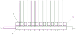
为了实现本发明的上述目的,本发明一种辅助天线阵面大规模阵元组装定位方法,其特征在于:首先,利用PCB基板或其它柔性基板,设计并制作成光热基板1,并在光热基板1两端组装好电源2、驱动模块3,光热基板1的正反两端面和天线阵面6组装导引柱4、石墨烯光源凸点5,每一个阵元安装孔的同心轴位置一一对应一个石墨烯光源凸点5,每个石墨烯光源凸点5对应导引柱4,光热基板1上的每一个组装导引柱4和天线阵面6上的每一个安装孔8一一装配焊锡环7,组装导引柱4从安装孔8的小孔径端装入,从大孔径端伸出,感知控制系统利用组装导引柱4伸出的长度作为焊锡环7的装配指引,实现机械臂对焊锡环7的自动组装,精确将焊锡环7装入安装孔8中;In order to achieve the above-mentioned purpose of the present invention, the present invention provides a method for assembling and positioning auxiliary antenna array large-scale array elements. Assemble the
石墨烯光源凸点5与安装孔8的小孔径端进行装配,每一个石墨烯光源凸点5和天线阵面6上的每一个安装孔8一一装配,在光热基板1的一端设置光热感应绑定头9,并将阵元10同轴装配在光热感应绑定头9中,同时引导机械臂快速将焊锡环7装入阵元10接口内;The graphene
石墨烯光源凸点5利用电源2、驱动模块3实现石墨烯光源凸点5的发光,并发热,产生热量,石墨烯光源凸点5发光、发热的位置与其天线阵面6的安装孔位置一一对应,实现精确定位后,并最终完成阵元10的高精度组装。The graphene
本发明相比于现有技术具有如下优点:Compared with the prior art, the present invention has the following advantages:
本发明利用PCB基板或其它柔性基板,设计并制作成光热基板1,并在光热基板1两端组装好电源2、驱动模块3,光热基板1的正反两端面和天线阵面6组装导引柱4、石墨烯光源凸点5,与已有的高精度定位技术相比,对物料一致性要求低,比视觉识别更可靠,比定位工装定位精度高,比图像识别具备更好的鲁棒性和自适应能力。The present invention uses a PCB substrate or other flexible substrates to design and manufacture a
本发明采用每一个阵元安装孔的同心轴位置一一对应一个石墨烯光源凸点5,每个石墨烯光源凸点5对应导引柱4,光热基板1上的每一个组装导引柱4和天线阵面6上的每一个安装孔8一一装配焊锡环7,组装导引柱4从安装孔8的小孔径端装入,从大孔径端伸出,利用组装导引柱4伸出的长度作为焊锡环7的装配指引,实现机械臂对焊锡环7的自动组装,精确将焊锡环7装入安装孔8中;不仅能够实现快速、高效、高可靠组装定位,还具备组装完成后阵元的电性能检测能力。In the present invention, the position of the concentric axis of each array element installation hole corresponds to a graphene
本发明在光热基板1的一端设置光热感应绑定头9,并将阵元10同轴装配在光热感应绑定头9中,同时引导机械臂快速将焊锡环7装入阵元10接口内;石墨烯光源凸点5利用电源2、驱动模块3实现石墨烯光源凸点5的发光,并发热,产生热量,石墨烯光源凸点5发光、发热的位置与其天线阵面6的安装孔位置一一对应,实现精确定位后,并最终完成阵元10的高精度组装。由于感知控制系统具备较高的智能化程度和自适应调节能力,能够根据不同的任务实现自主配置,满足定制和个性化产品的自适应制造;感知控制系统作为一个模块,能够方便地嵌入到整个装备中,并通过应用接口实现与其他模块的无缝连接和实时通信,且具备良好的可配置和可重构能力,能够显著提高阵元的组装效率和组装质量。In the present invention, a photothermal
本发明可以用于天线阵面大规模阵元高精度组装辅助定位与检测的光热基板,特别适用于大规模阵元的自动化组装工艺。The invention can be used for the photothermal substrate for the high-precision assembly of large-scale array elements of the antenna array to assist positioning and detection, and is especially suitable for the automatic assembly process of large-scale array elements.
附图说明Description of drawings
图1是本发明辅助天线阵面大规模阵元组装定位的分解示意图;Fig. 1 is an exploded schematic view of the assembly and positioning of large-scale array elements of the auxiliary antenna array of the present invention;
图2是图1的光热基板组装示意图;Fig. 2 is a schematic diagram of the assembly of the photothermal substrate in Fig. 1;
图3是图2光热基板组装天线阵面的示意图;Fig. 3 is a schematic diagram of the antenna array assembled with the photothermal substrate in Fig. 2;
图中:1、光热基板,2、电源,3、驱动,4、导引柱,5、石墨烯光源凸点,6、天线阵面7、焊锡环 8、安装口 9、光热感应绑定头 10、阵元。In the figure: 1. Photothermal substrate, 2. Power supply, 3. Drive, 4. Guide column, 5. Graphene light source bump, 6.
具体实施方式Detailed ways
参阅图1-图3。根据本发明,首先,利用PCB基板或其它柔性基板,设计并制作成光热基板1,并在光热基板1两端组装好电源2、驱动模块3,光热基板1的正反两端面分别设有组装导引柱4、石墨烯光源凸点5,每一个阵元安装孔的同心轴位置一一对应一个石墨烯光源凸点5和导引柱4,光热基板1上的每一个组装导引柱4和天线阵面6上的每一个安装孔8一一装配焊锡环7,组装导引柱4从安装孔8的小孔径端装入,从大孔径端伸出,利用组装导引柱4伸出的长度作为焊锡环7的装配指引,实现机械臂对焊锡环7的自动组装,精确将焊锡环7装入安装孔8中;See Figures 1-3. According to the present invention, firstly, a
石墨烯光源凸点5与安装孔8的小孔径端进行装配,每一个石墨烯光源凸点5和天线阵面6上的每一个安装孔8一一装配,在光热基板1的一端设置光热感应绑定头9,并将阵元10同轴装配在光热感应绑定头9中,同时引导机械臂快速将焊锡环7装入阵元10接口内;The graphene
石墨烯光源凸点5利用电源2、驱动模块3实现石墨烯光源凸点5的发光,并发热,产生热量,石墨烯光源凸点5发光、发热的位置与其天线阵面6的安装孔位置一一对应,实现精确定位后,并最终完成阵元10的高精度组装。The graphene
引导感知控制系统集成的光热感应绑定头9快速、精确发现每一个发光、发热源,根据石墨烯光源凸点5发光后同样会产生热量并会发热的原理,在系统上集成的光热感应绑定头9通过感知光和热,准确发现并精确找到阵元安装孔的中心位置,并用于引导阵面阵元SMP的组装与电性能检测,实现通断和驻波检测;感知控制系统利用石墨烯光源凸点5,可以实现对已经完成安装和焊接的阵元10的电性能检测。The light-heat
本实施例首先,利用PCB基板或其它柔性基板,设计并制作成光热基板1,并在光热基板1上组装好电源2、驱动模块3,光热基板1的正反两端面均可以和天线阵面6进行装配。当需要安装焊锡环7时,光热基板1上的每一个组装导引柱4和天线阵面6上的每一个安装孔8一一装配(组装导引柱4从安装孔8的小孔径端装入,从大孔径端伸出),并利用组装导引柱4伸出的长度作为焊锡环7的装配指引,实现机械臂对焊锡环7的自动组装,并精确将焊锡环7装入安装孔8中。当需要进行辅助定位与检测时,光热基板1上的每一个石墨烯光源凸点5和天线阵面6上的每一个安装孔8一一装配(石墨烯光源凸点5与安装孔8的小孔径端进行装配),利用电源2、驱动3,实现石墨烯光源凸点5的发光,石墨烯光源凸点5发光后必然会产生热量,并发热,可以引导系统集成的光热感应绑定头9快速、精确发现每一个发光、发热源,而该发光、发热源的位置即为天线阵面6的安装孔位置(因为石墨烯光源凸点5发光、发热的位置与其一一对应),实现精确定位后,并最终完成阵元10的高精度组装。同样,利用石墨烯光源凸点5,可以实现对已经完成安装和焊接的阵元10的电性能检测,主要可以实现通断和驻波检测。In this embodiment, firstly, a
参阅图2、图3。在辅助天线阵面大规模阵元组装定位中,采集待加工零件的图像,对目标位置和类别进行人工标注,具体地,在图像标注软件中使用锚框圈出装配点的边界,标记为正类并保存。图像标注软件选择并自动生成相应算法的标签格式,标签格式包括json、voc、yolo数据集标签格式,对于yolo算法,其解析后的标签信息为x_center中心,y_center中心为锚框的中心坐标,width,height为锚框的宽和高,相关算法自动解析标签信息,得到目标的类别和位置信息。Refer to Figure 2 and Figure 3. In the large-scale array element assembly and positioning of the auxiliary antenna array, the images of the parts to be processed are collected, and the target position and category are manually marked. Specifically, the boundary of the assembly point is circled by the anchor frame in the image marking software, and marked as positive class and save. The image annotation software selects and automatically generates the label format of the corresponding algorithm. The label format includes json, voc, and yolo dataset label formats. For the yolo algorithm, the parsed label information is the center of x_center, the center of y_center is the center coordinate of the anchor box, width ,height is the width and height of the anchor box, and the relevant algorithm automatically parses the label information to obtain the category and location information of the target.
图像标注是指在预先采集到的工件图像上使用相关图像标注软件,手工标注出待装配位置点的类别和位置信息,用于模型的训练。Image annotation refers to using relevant image annotation software on pre-collected workpiece images to manually mark the category and location information of the points to be assembled for model training.
在实际应用时,摄像机采集到工件图像后传输到计算机,输入到训练好的深度学习模型进行识别和定位,得到待加工位置的坐标信息,并最终与机械手进行坐标转化,机械手根据相应坐标移动,移动过程中可拍摄新的图像,处理后更新位置坐标,直到得到较准确的位置进行零件的装配。In practical application, the camera collects the image of the workpiece and transmits it to the computer, and inputs it to the trained deep learning model for identification and positioning, obtains the coordinate information of the position to be processed, and finally performs coordinate conversion with the manipulator, and the manipulator moves according to the corresponding coordinates. New images can be taken during the moving process, and the position coordinates can be updated after processing until a more accurate position is obtained for parts assembly.
在电性能检测中,基于深度学习的目标检测算法软件将自动识别出图像中的装配点并用锚框标记出位置,同时以装配点坐标输出锚框的中心坐标,并将原图像和标注图像输入到预训练模型中进行训练,利用神经网络学习生成候选区域和可能区域(RegionProposal)&CNN提取特征,再对区域进行卷积,将图片卷积后提取的特征图分为SxS块,然后利用分类模型对每一块进行分类,结合不同尺寸大小特征地图FeatureMaps映射所提取的特征进行预测,然后在不同观察距离处检测不同的目标类型,使用不同大小和宽高比的窗口,从左到右、从上到下滑动窗口,在特征图上滑动窗口来检测目标,根据滑动窗口从图像中剪切图像块,将特征图平滑化图像块输入CNN分类器中,提取整个图像的特征,然后将创建候选区域,将候选区域直接应用到提取到的特征图,创建多窗口来检测不同位置的不同目标,随后结合对应的特征图以裁剪为特征图块,并用于目标检测任务中,利用分类识别目标,得到深度学习模型参数。从而降低信息冗余程度,提高检测速度,而且加快了训练速度。In the electrical performance detection, the target detection algorithm software based on deep learning will automatically identify the assembly point in the image and mark the position with the anchor frame, and at the same time output the center coordinates of the anchor frame with the coordinates of the assembly point, and input the original image and the marked image Go to the pre-training model for training, use the neural network to learn to generate candidate regions and possible regions (RegionProposal) & CNN to extract features, then convolve the regions, divide the feature maps extracted after image convolution into SxS blocks, and then use the classification model Classify each block, combine the features extracted by FeatureMaps mapping of different sizes to predict, and then detect different target types at different observation distances, using windows of different sizes and aspect ratios, from left to right, from top To the lower sliding window, slide the window on the feature map to detect the target, cut the image block from the image according to the sliding window, input the smoothed image block of the feature map into the CNN classifier, extract the features of the entire image, and then create the candidate area , apply the candidate area directly to the extracted feature map, create multiple windows to detect different targets in different positions, and then combine the corresponding feature maps to crop them into feature blocks, and use them in target detection tasks, use classification to identify targets, and get Deep learning model parameters. Thereby reducing the degree of information redundancy, improving the detection speed, and speeding up the training speed.
通过在选择性搜索(selectivesearch,SS)中,首先将每个像素作为一组,然后,计算每一组的纹理,并将两个最接近的组结合起来,继续合并区域,直到所有区域都结合在一起。By first treating each pixel as a group in a selective search (SS), then computing the texture for each group and combining the two closest groups, continuing to merge regions until all regions are combined together.
在输入全连接层前定义池化层,使用ROI池化将特征图块转换为固定的大小,找到每个部分的最大值,得到变换后的特征图,并馈送到全连接层进行分类和定位,基于ROI提取的多目标图像水平集分割,将ROI拆分为目标维度,并将输入的任意尺度featuremaps组合成特定维度的输出。能显著地减少处理时间。Define the pooling layer before inputting the fully connected layer, use ROI pooling to convert the feature block to a fixed size, find the maximum value of each part, get the transformed feature map, and feed it to the fully connected layer for classification and positioning , multi-target image level set segmentation based on ROI extraction, splits ROIs into target dimensions, and combines input featuremaps of arbitrary scales into dimension-specific outputs. Can significantly reduce processing time.
R-CNN对候选框区域进行分类,应用卷积核进行预测,检测不同类别的目标,判断有没有物体,如有则对边框回归BoundingBox进行精修回归,将查询结果rbg原有结构改成并行—在分类的同时,对Bbox进行回归,使用回归的方式输出目标的边框和类别,将Bbox和Clf的loss结合起来变成一个Loss一起训练,处理不同分辨率的输入图像,分别传递到各个特征图,通过多个特征图完成检测。更具体地做法,是将输入图片划分成一个SxS的网格,每个网格负责检测网格里面的物体,并输出BboxInfo和置信度。这里的置信度指的是该检测网格内含有什么物体和预测这个物体的准确度。R-CNN classifies the candidate frame area, applies the convolution kernel to predict, detects different types of targets, and judges whether there is an object. If there is, it performs refined regression on the border regression BoundingBox, and changes the original structure of the query result rbg to parallel —Regress Bbox at the same time as classification, use regression to output the border and category of the target, combine the loss of Bbox and Clf into a Loss to train together, process input images of different resolutions, and pass them to each feature The detection is done through multiple feature maps. More specifically, the input image is divided into an SxS grid, and each grid is responsible for detecting objects in the grid, and outputting BboxInfo and confidence. Confidence here refers to what object is contained in the detection grid and the accuracy of predicting this object.
该类目标检测算法的优点是不需要人工设计特征,并具有较好的鲁棒性,经过近年来的不断优化在算法精度和效率上均取得了较好的结果。使用该类目标检测算法,需要提前采集待加工零件的图像,对目标位置和类别进行人工标注,得到深度学习模型参数。装配目标点进行识别和定位。The advantage of this type of target detection algorithm is that it does not require manual design features and has good robustness. After continuous optimization in recent years, good results have been achieved in algorithm accuracy and efficiency. To use this type of target detection algorithm, it is necessary to collect images of the parts to be processed in advance, manually mark the target position and category, and obtain the parameters of the deep learning model. Assembly target points are identified and localized.
以上所述仅是实现本发明的优选实施方案,应当理解本发明并非局限于本文所披露的形式,不应看作是对其他实施例的排除,而可用于各种其他组合、修改和环境,并能够在本文所述构想范围内,通过上述教导或相关领域的技术或知识进行改动。而本领域人员所进行的改动和变化不脱离本发明的精神和范围,则都应在本发明所附权利要求的保护范围内。The above descriptions are only preferred embodiments for realizing the present invention. It should be understood that the present invention is not limited to the form disclosed herein, and should not be regarded as excluding other embodiments, but can be used in various other combinations, modifications and environments. Modifications can be made within the scope of the ideas described herein through the teachings above or by skill or knowledge in the relevant art. However, changes and changes made by those skilled in the art do not depart from the spirit and scope of the present invention, and should all be within the protection scope of the appended claims of the present invention.
Claims (7)
Priority Applications (1)
| Application Number | Priority Date | Filing Date | Title |
|---|---|---|---|
| CN202210547717.2A CN115070407B (en) | 2022-05-18 | 2022-05-18 | Method for assembling and positioning array elements of auxiliary antenna array surface in large scale |
Applications Claiming Priority (1)
| Application Number | Priority Date | Filing Date | Title |
|---|---|---|---|
| CN202210547717.2A CN115070407B (en) | 2022-05-18 | 2022-05-18 | Method for assembling and positioning array elements of auxiliary antenna array surface in large scale |
Publications (2)
| Publication Number | Publication Date |
|---|---|
| CN115070407A CN115070407A (en) | 2022-09-20 |
| CN115070407B true CN115070407B (en) | 2023-07-11 |
Family
ID=83249934
Family Applications (1)
| Application Number | Title | Priority Date | Filing Date |
|---|---|---|---|
| CN202210547717.2A Active CN115070407B (en) | 2022-05-18 | 2022-05-18 | Method for assembling and positioning array elements of auxiliary antenna array surface in large scale |
Country Status (1)
| Country | Link |
|---|---|
| CN (1) | CN115070407B (en) |
Families Citing this family (1)
| Publication number | Priority date | Publication date | Assignee | Title |
|---|---|---|---|---|
| CN118664329B (en) * | 2024-08-23 | 2024-10-22 | 成都华信佳亿科技有限公司 | Auxiliary assembly equipment for biconical antenna |
Citations (12)
| Publication number | Priority date | Publication date | Assignee | Title |
|---|---|---|---|---|
| EP0621654A2 (en) * | 1993-04-19 | 1994-10-26 | Hughes Aircraft Company | An active antenna array |
| CN1711817A (en) * | 2002-12-03 | 2005-12-21 | 松下电器产业株式会社 | Electronic parts mounting apparatus and method |
| CN107276644A (en) * | 2017-06-02 | 2017-10-20 | 歌尔股份有限公司 | Form-giving array antennas beams method and system |
| CN108333484A (en) * | 2018-01-23 | 2018-07-27 | 国网河北省电力有限公司电力科学研究院 | A kind of detection method of local discharge of electrical equipment |
| CN108963705A (en) * | 2018-07-12 | 2018-12-07 | 中国船舶重工集团公司第七二四研究所 | A kind of 64 channel T/R assembly connector blindmate Fixture Design methods |
| CN109616759A (en) * | 2018-12-06 | 2019-04-12 | 西南电子技术研究所(中国电子科技集团公司第十研究所) | Full-duplex active phased array filter antenna array |
| CN111251336A (en) * | 2019-06-29 | 2020-06-09 | 浙江大学 | A dual-arm collaborative intelligent assembly system based on visual positioning |
| CN111947483A (en) * | 2019-05-14 | 2020-11-17 | 珠海盾安热工科技有限公司 | Heat exchange tube assembly, heat exchanger and assembly method of heat exchange tube assembly |
| CN113478220A (en) * | 2021-07-08 | 2021-10-08 | 中山市美格电子科技有限公司 | Anode assembly welding wire automatic assembly device |
| CN113939179A (en) * | 2021-10-12 | 2022-01-14 | 广州市番禺致丰微电器有限公司 | PCB plug-in components feeding system through laser guide installation |
| CN215787967U (en) * | 2021-09-14 | 2022-02-11 | 东莞市领尖自动化设备有限公司 | Welding ring automatic assembly mechanism |
| CN216177982U (en) * | 2021-10-29 | 2022-04-05 | 珠海励高精工制造有限公司 | Automatic ring piece assembling device |
Family Cites Families (2)
| Publication number | Priority date | Publication date | Assignee | Title |
|---|---|---|---|---|
| WO2007129309A1 (en) * | 2006-05-02 | 2007-11-15 | Galil Medical Ltd. | Probe insertion guide with user-directing features |
| US9923273B2 (en) * | 2013-12-02 | 2018-03-20 | A.K. Stamping Company, Inc. | System for manufacturing and tuning an NFC antenna |
-
2022
- 2022-05-18 CN CN202210547717.2A patent/CN115070407B/en active Active
Patent Citations (12)
| Publication number | Priority date | Publication date | Assignee | Title |
|---|---|---|---|---|
| EP0621654A2 (en) * | 1993-04-19 | 1994-10-26 | Hughes Aircraft Company | An active antenna array |
| CN1711817A (en) * | 2002-12-03 | 2005-12-21 | 松下电器产业株式会社 | Electronic parts mounting apparatus and method |
| CN107276644A (en) * | 2017-06-02 | 2017-10-20 | 歌尔股份有限公司 | Form-giving array antennas beams method and system |
| CN108333484A (en) * | 2018-01-23 | 2018-07-27 | 国网河北省电力有限公司电力科学研究院 | A kind of detection method of local discharge of electrical equipment |
| CN108963705A (en) * | 2018-07-12 | 2018-12-07 | 中国船舶重工集团公司第七二四研究所 | A kind of 64 channel T/R assembly connector blindmate Fixture Design methods |
| CN109616759A (en) * | 2018-12-06 | 2019-04-12 | 西南电子技术研究所(中国电子科技集团公司第十研究所) | Full-duplex active phased array filter antenna array |
| CN111947483A (en) * | 2019-05-14 | 2020-11-17 | 珠海盾安热工科技有限公司 | Heat exchange tube assembly, heat exchanger and assembly method of heat exchange tube assembly |
| CN111251336A (en) * | 2019-06-29 | 2020-06-09 | 浙江大学 | A dual-arm collaborative intelligent assembly system based on visual positioning |
| CN113478220A (en) * | 2021-07-08 | 2021-10-08 | 中山市美格电子科技有限公司 | Anode assembly welding wire automatic assembly device |
| CN215787967U (en) * | 2021-09-14 | 2022-02-11 | 东莞市领尖自动化设备有限公司 | Welding ring automatic assembly mechanism |
| CN113939179A (en) * | 2021-10-12 | 2022-01-14 | 广州市番禺致丰微电器有限公司 | PCB plug-in components feeding system through laser guide installation |
| CN216177982U (en) * | 2021-10-29 | 2022-04-05 | 珠海励高精工制造有限公司 | Automatic ring piece assembling device |
Non-Patent Citations (1)
| Title |
|---|
| 有源相控阵天线集成设计;顾叶青;姚晔;王超;;电子机械工程(第06期);全文 * |
Also Published As
| Publication number | Publication date |
|---|---|
| CN115070407A (en) | 2022-09-20 |
Similar Documents
| Publication | Publication Date | Title |
|---|---|---|
| Chen et al. | A comprehensive review of deep learning-based PCB defect detection | |
| CN113643280B (en) | A plate sorting system and method based on computer vision | |
| CN102636120B (en) | Visual servo secondary locating system for LED (light emitting diode) chip and locating method of visual servo secondary locating system | |
| CN102133565B (en) | Control method and system for COB (Chip on Board) glue sealing machine based on visual orientation technology | |
| CN109900706A (en) | A kind of weld seam and weld defect detection method based on deep learning | |
| CN115082559B (en) | Multi-target intelligent sorting method and system for flexible parts and storage medium | |
| CN110865077B (en) | Visual inspection system for appearance defects in RFID antenna production | |
| CN114863250B (en) | Container lock hole identification and positioning method, system and storage medium | |
| Liu et al. | Research on deviation detection of belt conveyor based on inspection robot and deep learning | |
| CN108460552B (en) | A steel storage control system based on machine vision and PLC | |
| CN113838010B (en) | Intelligent detection method of composite material damage based on infrared heat wave and convolutional neural network | |
| CN115070407B (en) | Method for assembling and positioning array elements of auxiliary antenna array surface in large scale | |
| CN114092411A (en) | Efficient and rapid binocular 3D point cloud welding spot defect detection method | |
| CN118952193A (en) | A method of point cloud scanning guided by vision of robotic arm based on deep learning | |
| Yao et al. | A detection algorithm for surface defects of printed circuit board based on improved yolov8 | |
| CN112084875B (en) | A multi-lidar coordinate system and method | |
| Zhang et al. | MA-SPRNet: A multiple attention mechanisms-based network for self-piercing riveting joint defect detection | |
| CN119635726B (en) | Mobile monitoring platform based on thermal imaging camera | |
| CN119832317B (en) | Point counting-based steel bar semi-finished product point inspection embedded system | |
| CN207976755U (en) | A kind of steel warehouse control system based on machine vision and PLC | |
| Lan et al. | Dal-yolo: a multi-target detection model for UAV-based road maintenance integrating feature pyramid and attention mechanisms | |
| CN208314563U (en) | A kind of visual identifying system for robotic tracking | |
| CN117381793A (en) | A vision system for intelligent material detection based on deep learning | |
| CN116843615A (en) | Lead frame intelligent total inspection method based on flexible light path | |
| CN116481637A (en) | A method and system for identifying and monitoring abnormal mechanical vibration with flexible sensing |
Legal Events
| Date | Code | Title | Description |
|---|---|---|---|
| PB01 | Publication | ||
| PB01 | Publication | ||
| SE01 | Entry into force of request for substantive examination | ||
| SE01 | Entry into force of request for substantive examination | ||
| GR01 | Patent grant | ||
| GR01 | Patent grant | ||
| TR01 | Transfer of patent right | ||
| TR01 | Transfer of patent right |
Effective date of registration: 20250902 Address after: 610000 Sichuan Province, Chengdu City, Gaoxin West District, Xixin Road No. 3, Guoteng Garden, Building 9, Room 206 Patentee after: Chengdu Zhongyi Technology Co.,Ltd. Country or region after: China Address before: 611731 Chengdu province high tech Zone (West) West source Avenue, No. 2006 Patentee before: University of Electronic Science and Technology of China Country or region before: China |