CN115064396B - A flattening device for processing winding cores of film capacitors to prevent inward wrinkling - Google Patents
A flattening device for processing winding cores of film capacitors to prevent inward wrinkling Download PDFInfo
- Publication number
- CN115064396B CN115064396B CN202210606779.6A CN202210606779A CN115064396B CN 115064396 B CN115064396 B CN 115064396B CN 202210606779 A CN202210606779 A CN 202210606779A CN 115064396 B CN115064396 B CN 115064396B
- Authority
- CN
- China
- Prior art keywords
- adjusting disc
- rod
- assembly
- flattening device
- film capacitors
- Prior art date
- Legal status (The legal status is an assumption and is not a legal conclusion. Google has not performed a legal analysis and makes no representation as to the accuracy of the status listed.)
- Active
Links
Images


Classifications
-
- H—ELECTRICITY
- H01—ELECTRIC ELEMENTS
- H01G—CAPACITORS; CAPACITORS, RECTIFIERS, DETECTORS, SWITCHING DEVICES, LIGHT-SENSITIVE OR TEMPERATURE-SENSITIVE DEVICES OF THE ELECTROLYTIC TYPE
- H01G13/00—Apparatus specially adapted for manufacturing capacitors; Processes specially adapted for manufacturing capacitors not provided for in groups H01G4/00 - H01G11/00
- H01G13/02—Machines for winding capacitors
Landscapes
- Engineering & Computer Science (AREA)
- Power Engineering (AREA)
- Manufacturing & Machinery (AREA)
- Microelectronics & Electronic Packaging (AREA)
- Fixed Capacitors And Capacitor Manufacturing Machines (AREA)
Abstract
本发明公开了一种防止内卷褶皱的薄膜电容器卷绕芯子加工用压扁装置,包括安装组件,所述安装组件还包括有安装座,所述安装座的下端固定安装有固定支腿,所述安装座的内部设置有输送带,所述输送带和安装座的连接处设置有第一内置轴承,所述安装座的右端上表面设置有承接座;推动组件,所述推动组件还包括有固定安装架,所述固定安装架的内部设置有活动杆,所述活动杆的前后两端上侧设置有第一调节盘。该防止内卷褶皱的薄膜电容器卷绕芯子加工用压扁装置,有利于对薄膜电容器卷绕芯子进行压扁操作且避免造成内卷褶皱,能够对操作后的薄膜电容器卷绕芯子进行有效的收集,优化操作简单结构简单,且提高了该装置的实用效果。
The invention discloses a flattening device for processing winding cores of film capacitors for preventing inward wrinkling. The inside of the mounting base is provided with a conveyor belt, the connection between the conveyor belt and the mounting base is provided with a first built-in bearing, and the upper surface of the right end of the mounting base is provided with a receiving seat; a push assembly, the push assembly also includes There is a fixed installation frame, the inside of the fixed installation frame is provided with a movable rod, and the upper side of the front and rear ends of the movable rod is provided with a first adjusting disc. The film capacitor winding core processing flattening device that prevents inward wrinkling is beneficial to the flattening operation of the film capacitor winding core and avoids inward wrinkling, and can carry out the operation on the film capacitor winding core after operation. The utility model has the advantages of effective collection, simple operation and simple structure, and improves the practical effect of the device.
Description
技术领域technical field
本发明涉及薄膜电容器卷绕芯子相关技术领域,具体为一种防止内卷褶皱的薄膜电容器卷绕芯子加工用压扁装置。The invention relates to the technical field related to winding cores of film capacitors, in particular to a flattening device for processing winding cores of film capacitors that prevents inwardly rolling wrinkles.
背景技术Background technique
薄膜电容器又称塑料薄膜电容,其以塑料薄膜为电介质,薄膜电容器由于具有很多优良的特性,因此是一种性能优秀的电容器,它的主要等性如下:无极性,绝缘阻抗很高,频率特性优异,而且介质损失很小,金属化薄膜电容器因其绝缘阻抗高、电容量损失小、可靠安全防爆的性能,在电子、通讯、电力等领域得到广泛使用。金属化薄膜是制成金属化薄膜电容器的主要材料,该材料的基材为有机薄膜如聚酯、聚丙烯等,将金属通过真空镀膜的方式镀在介质基材上。电容器由两张或两张以上的金属化薄膜、素膜卷绕而成,金属化薄膜的金属镀层非常薄,非常容易氧化,如果在制成过程中产生褶皱,而褶皱中会含有空气或水分,那么此处的金属镀层容易发生电离或氧化,从而降低电容器的特性,电容器容量将降低衰减或失效,内层薄膜展平不良,导致ESR增加,内部空隙导致喷金渗入,引起短路。尤其对于应用在新能源汽车、电气化机车、太阳能发电等直流支撑场合的电容器,如果电容器失效,会带来巨大的损失,在对薄膜电容器进行加工时,通常需要通过卷绕装置将塑料薄膜缠绕在电容器上,因此在薄膜电容器卷绕芯子加工过程中需要用到一种压扁装置,但现有的大部分装置还存在一些缺陷,如:Film capacitors, also known as plastic film capacitors, use plastic films as dielectrics. Film capacitors have many excellent characteristics, so they are capacitors with excellent performance. Its main properties are as follows: non-polarity, high insulation resistance, frequency characteristics Excellent, and the dielectric loss is very small, metallized film capacitors are widely used in electronics, communications, electric power and other fields because of their high insulation resistance, small capacitance loss, reliable, safe and explosion-proof performance. Metallized film is the main material for making metallized film capacitors. The base material of this material is an organic film such as polyester, polypropylene, etc., and the metal is plated on the dielectric base material by vacuum coating. The capacitor is wound by two or more metallized films and plain films. The metal plating layer of the metallized film is very thin and is very easy to oxidize. If there are wrinkles during the manufacturing process, the wrinkles will contain air or moisture , then the metal plating here is prone to ionization or oxidation, thereby reducing the characteristics of the capacitor, the capacitor capacity will be reduced attenuation or failure, the inner film is not flattened, resulting in an increase in ESR, and the internal voids lead to gold spray penetration, causing a short circuit. Especially for capacitors used in DC support applications such as new energy vehicles, electrified locomotives, and solar power generation, if the capacitor fails, it will bring huge losses. When processing film capacitors, it is usually necessary to wind the plastic film on the Capacitors, so a flattening device is needed in the process of film capacitor winding core processing, but most of the existing devices still have some defects, such as:
现有技术方案存在以下缺陷:不便于对薄膜电容器卷绕芯子进行压扁操作且会造成内卷褶皱,不便于对操作后的薄膜电容器卷绕芯子进行有效的收集,操作困难结构复杂,且实用效果不佳,因此我们提出一种防止内卷褶皱的薄膜电容器卷绕芯子,以便于解决上述中提出的问题。The existing technical solutions have the following defects: it is inconvenient to flatten the winding core of the film capacitor and cause infolding wrinkles, it is not convenient to effectively collect the winding core of the film capacitor after operation, the operation is difficult and the structure is complicated, And the practical effect is not good, so we propose a film capacitor winding core that prevents inward wrinkling, so as to solve the above-mentioned problems.
发明内容Contents of the invention
本发明的目的在于提供一种防止内卷褶皱的薄膜电容器卷绕芯子加工用压扁装置,以解决上述背景技术中提出的不便于对薄膜电容器卷绕芯子进行压扁操作且会造成内卷褶皱,不便于对操作后的薄膜电容器卷绕芯子进行有效的收集,操作困难结构复杂,且实用效果不佳的问题。The purpose of the present invention is to provide a flattening device for processing winding cores of film capacitors that prevents inward wrinkling, so as to solve the problem that it is inconvenient to crush the winding cores of film capacitors and cause internal Wrinkles, it is not convenient to effectively collect the film capacitor winding core after operation, the operation is difficult, the structure is complicated, and the practical effect is not good.
为实现上述目的,本发明提供如下技术方案:一种防止内卷褶皱的薄膜电容器卷绕芯子加工用压扁装置,包括安装组件,所述安装组件还包括有安装座,所述安装座的下端固定安装有固定支腿,所述安装座的内部设置有输送带,且输送带的前后两侧均设置有防掉落边缘条,所述输送带和安装座的连接处设置有第一内置轴承,且输送带的后端安装有位于安装座内部的第一驱动电机,所述安装座的右端上表面设置有承接座;In order to achieve the above object, the present invention provides the following technical solutions: a flattening device for processing winding cores of film capacitors that prevents inward wrinkling, including a mounting assembly, and the mounting assembly also includes a mounting seat, the mounting seat The lower end is fixedly installed with fixed legs, the interior of the installation seat is provided with a conveyor belt, and the front and rear sides of the conveyor belt are provided with anti-drop edge strips, and the connection between the conveyor belt and the installation seat is provided with a first built-in Bearings, and the rear end of the conveyor belt is equipped with a first drive motor located inside the installation seat, and the upper surface of the right end of the installation seat is provided with a receiving seat;
推动组件,所述推动组件还包括有固定安装架,所述固定安装架的内部设置有活动杆,且活动杆的下端设置有与固定安装架相连接的第一连接件,所述活动杆的前后两端上侧设置有第一调节盘,且第一调节盘的内端设置有联动轴杆,所述联动轴杆的中部设置有第二调节盘,且第二调节盘的上端连接有第一调节杆,并且第一调节杆的左端设置有位于固定安装架上端的第二驱动电机;The push assembly, the push assembly also includes a fixed mount, a movable rod is arranged inside the fixed mount, and the lower end of the movable rod is provided with a first connecting piece connected with the fixed mount, the movable rod The upper side of the front and rear ends is provided with a first adjustment disc, and the inner end of the first adjustment disc is provided with a linkage shaft, the middle part of the linkage shaft is provided with a second adjustment disc, and the upper end of the second adjustment disc is connected with a second adjustment disc. An adjustment rod, and the left end of the first adjustment rod is provided with a second drive motor positioned at the upper end of the fixed mount;
拉伸组件,所述拉伸组件还包括有外壳体,所述外壳体固定安装在推动组件的右端下侧,且外壳体的后端安装有第三驱动电机,所述第三驱动电机的前端设置有第二调节杆,且第二调节杆和外壳体的连接处设置有第二内置轴承,所述第二内置轴承的外侧设置有活动滑杆,且活动滑杆的右端设置有连接撑杆;The stretching assembly, the stretching assembly also includes an outer casing, the outer casing is fixedly installed on the lower side of the right end of the pushing assembly, and the rear end of the outer casing is equipped with a third drive motor, and the front end of the third drive motor A second adjustment rod is provided, and a second built-in bearing is provided at the joint between the second adjustment rod and the outer shell, a movable sliding rod is provided on the outside of the second built-in bearing, and a connecting strut is provided at the right end of the movable sliding rod ;
输送组件,所述输送组件还包括有固定座,所述固定座设置在拉伸组件的下侧并与安装组件相连接,且固定座的上方设置有活动板,所述活动板的左端下侧设置有与固定座相连接的第二连接件,且第二连接件的左端设置有与推动组件相连接的第一电动伸缩杆;The conveying assembly, the conveying assembly also includes a fixed seat, the fixed seat is arranged on the lower side of the stretching assembly and connected with the installation assembly, and a movable plate is arranged above the fixed seat, and the lower side of the left end of the movable plate A second connecting piece connected to the fixed seat is provided, and the left end of the second connecting piece is provided with a first electric telescopic rod connected with the push assembly;
挤压组件,所述挤压组件还包括有外框架,所述外框架设置在安装组件的中部上表面,且外框架的内部上侧安装有第二电动伸缩杆,所述第二电动伸缩杆的下端设置有支撑架,且支撑架的下端设置有盒体,所述盒体的内部后侧安装有第四驱动电机,且第四驱动电机的前端设置有第三调节盘,所述第三调节盘的外侧设置有第四调节盘,且第四调节盘和盒体的连接处设置有第三内置轴承,所述第四调节盘的外侧设置有柔性内齿压制带,所述第三调节盘的下端设置有与柔性内齿压制带内侧相贴合的自重抵压板。Extrusion assembly, the extrusion assembly also includes an outer frame, the outer frame is arranged on the upper surface of the middle part of the installation assembly, and a second electric telescopic rod is installed on the inner upper side of the outer frame, and the second electric telescopic rod The lower end of the support frame is provided with a support frame, and the lower end of the support frame is provided with a box body, the inner rear side of the box body is installed with a fourth drive motor, and the front end of the fourth drive motor is provided with a third adjustment disc, the third The outer side of the adjusting disc is provided with a fourth adjusting disc, and the connection between the fourth adjusting disc and the box body is provided with a third built-in bearing, the outer side of the fourth adjusting disc is provided with a flexible internal tooth pressing belt, and the third adjusting disc The lower end of the disc is provided with a self-weight resisting plate that fits the inner side of the flexible internal tooth pressing belt.
采用上述技术方案,能够在安装组件、推动组件、拉伸组件、输送组件和挤压组件的作用下对薄膜电容器卷绕芯子进行有效的加工处理。By adopting the above technical solution, the winding core of the film capacitor can be effectively processed under the action of the installation component, the pushing component, the stretching component, the conveying component and the extruding component.
作为本发明的优选技术方案,所述防掉落边缘条关于输送带的中心线前后对称设置,且输送带通过第一内置轴承在安装座上构成转动结构。As a preferred technical solution of the present invention, the anti-drop edge strips are symmetrically arranged front and rear with respect to the center line of the conveyor belt, and the conveyor belt forms a rotating structure on the mounting seat through the first built-in bearing.
采用上述技术方案,能够在打开第一驱动电机转动输送带的时候,对加工后的薄膜电容器卷绕芯子进行准确的输送,便于收集。By adopting the above technical solution, when the first driving motor is turned on to rotate the conveyor belt, the processed film capacitor winding cores can be accurately conveyed, which is convenient for collection.
作为本发明的优选技术方案,所述活动杆通过第一连接件在固定安装架上构成卡合式滑动结构,且活动杆的上端设置有凸状结构,并且活动杆与第一调节盘之间采用啮合的方式相连接。As a preferred technical solution of the present invention, the movable rod forms a snap-fit sliding structure on the fixed mounting frame through the first connecting piece, and the upper end of the movable rod is provided with a convex structure, and a connected in a meshing manner.
采用上述技术方案,能够使活动杆向右移动的时候将薄膜电容器卷绕芯子推动到承接座上进行压扁。By adopting the above technical solution, when the movable rod moves to the right, the winding core of the film capacitor can be pushed onto the receiving seat for flattening.
作为本发明的优选技术方案,所述第一调节盘通过焊接与联动轴杆和第二调节盘均构成一体化结构,且第二调节盘与第一调节杆之间采用啮合的方式相连接。As a preferred technical solution of the present invention, the first adjusting disc forms an integrated structure with the linkage shaft rod and the second adjusting disc through welding, and the second adjusting disc is connected with the first adjusting rod in an engaging manner.
采用上述技术方案,能够在打开第二驱动电机转动第一调节杆的时候,在啮合连接的作用下带动第二调节盘进行同步转动。By adopting the above technical solution, when the second driving motor is turned on to rotate the first adjusting rod, the second adjusting disc can be driven to rotate synchronously under the action of the meshing connection.
作为本发明的优选技术方案,所述第二调节杆通过第二内置轴承在外壳体上构成转动结构,且第二调节杆与活动滑杆之间采用螺纹的方式相连接。As a preferred technical solution of the present invention, the second adjusting rod forms a rotating structure on the outer casing through the second built-in bearing, and the second adjusting rod is connected to the movable sliding rod in a threaded manner.
采用上述技术方案,能够在打开第三驱动电机转动第二调节杆的时候,使转动转动状态的第二调节杆带动螺纹连接的活动滑杆进行前后移动,通过第二调节杆的螺纹方向关于外壳体的中心线前后呈相反设置,能够对活动滑杆进行前后单独移动。By adopting the above technical scheme, when the third driving motor is turned on to rotate the second adjusting rod, the second adjusting rod in the rotating state drives the movable sliding rod connected with the thread to move back and forth, and the thread direction of the second adjusting rod is relative to the housing The center line of the body is oppositely arranged front and back, and the movable slide bar can be moved back and forth independently.
作为本发明的优选技术方案,所述活动滑杆通过焊接连接撑杆之间构成一体化结构,且连接撑杆的右端贯穿于活动杆的右端内部。As a preferred technical solution of the present invention, the movable sliding rod is connected to the struts by welding to form an integrated structure, and the right end of the connecting strut passes through the inside of the right end of the movable rod.
采用上述技术方案,能够将拉伸过后的薄膜电容器卷绕芯子进行推动。By adopting the above technical solution, the stretched film capacitor winding core can be pushed.
作为本发明的优选技术方案,所述活动板通过第二连接件在固定座上构成卡合式滑动结构,且活动板的右端下表面与承接座的上表面呈贴合设置。As a preferred technical solution of the present invention, the movable plate forms an engaging sliding structure on the fixed seat through the second connecting piece, and the lower surface of the right end of the movable plate is attached to the upper surface of the receiving seat.
采用上述技术方案,能够在打开第一电动伸缩杆的时候利用活动板将压扁过后的薄膜电容器卷绕芯子推动到输送带上。By adopting the above technical solution, the movable plate can be used to push the flattened film capacitor winding core onto the conveyor belt when the first electric telescopic rod is opened.
作为本发明的优选技术方案,所述第三调节盘与第四调节盘之间采用啮合的方式相连接,且第四调节盘关于第三调节盘的中心线呈三等分设置。As a preferred technical solution of the present invention, the third adjusting disc is connected to the fourth adjusting disc in an engaging manner, and the fourth adjusting disc is arranged in three equal parts with respect to the centerline of the third adjusting disc.
采用上述技术方案,能够在打开第四驱动电机转动第三调节盘的时候,在啮合连接的作用下带动第四调节盘进行同步转动。By adopting the above technical solution, when the fourth driving motor is turned on to rotate the third adjusting disc, the fourth adjusting disc can be driven to rotate synchronously under the action of the meshing connection.
作为本发明的优选技术方案,所述第四调节盘通过第三内置轴承在盒体上构成转动结构,且第四调节盘与柔性内齿压制带之间采用啮合的方式相连接。As a preferred technical solution of the present invention, the fourth adjusting disc constitutes a rotating structure on the box body through the third built-in bearing, and the fourth adjusting disc is connected with the flexible internal tooth pressing belt in a meshing manner.
采用上述技术方案,能够在第四调节盘转动的时候带动柔性内齿压制带进行同步转动。By adopting the above technical solution, the flexible internal tooth pressing belt can be driven to rotate synchronously when the fourth adjusting disc rotates.
作为本发明的优选技术方案,所述第三调节盘的前端下侧设置有转动连接的自重抵压板,且自重抵压板的下表面与柔性内齿压制带的内部下侧呈贴合设置。As a preferred technical solution of the present invention, the lower front end of the third adjusting disc is provided with a rotatably connected self-weight pressing plate, and the lower surface of the self-weight pressing plate is arranged in close contact with the inner lower side of the flexible internal tooth pressing belt.
采用上述技术方案,能够在自重抵压板的作用下对柔性内齿压制带进行抵触,避免在压扁作用过程中导致柔性内齿压制带受损。By adopting the above technical solution, the flexible inner-tooth pressing belt can be resisted under the action of the self-weight pressing plate, so as to avoid damage to the flexible inner-tooth pressing belt during the flattening process.
与现有技术相比,本发明的有益效果是:该防止内卷褶皱的薄膜电容器卷绕芯子加工用压扁装置,有利于对薄膜电容器卷绕芯子进行压扁操作且避免造成内卷褶皱,能够对操作后的薄膜电容器卷绕芯子进行有效的收集,优化操作简单结构简单,且提高了该装置的实用效果;Compared with the prior art, the beneficial effect of the present invention is that the flattening device for processing winding cores of film capacitors for preventing inward wrinkling facilitates the flattening operation of winding cores of film capacitors and avoids causing inward winding Wrinkles can effectively collect the winding core of the film capacitor after operation, the optimized operation is simple and the structure is simple, and the practical effect of the device is improved;
1、设置支撑架通过焊接与盒体构成一体化结构,能够在打开第二电动伸缩杆驱动支撑架的时候,使柔性内齿压制带向下移动,从而对薄膜电容器卷绕芯子进行压扁操作,通过第三调节盘和柔性内齿压制带均与第四调节盘之间采用啮合的方式相连接,能够在打开第四驱动电机转动第三调节盘的时候,带动柔性内齿压制带进行同步转动,达到了可以对薄膜电容器卷绕芯子进行压扁,有效的提高了该装置的压扁效果;1. The support frame is set up to form an integrated structure through welding and the box body. When the second electric telescopic rod is opened to drive the support frame, the flexible internal tooth pressing belt can be moved downward, thereby flattening the winding core of the film capacitor. Operation, through the third adjustment disc and the flexible internal tooth pressing belt are connected with the fourth adjustment disc in a meshing manner, when the fourth drive motor is turned on to rotate the third adjustment disc, the flexible inner tooth pressing belt can be driven The synchronous rotation achieves the flattening of the winding core of the film capacitor, which effectively improves the flattening effect of the device;
2、设置活动板通过第二连接件在固定座上构成卡合式滑动结构,当打开第一电动伸缩杆的时候,可以使活动板将压扁后的薄膜电容器卷绕芯子从承接座上推动到输送带上,由于输送带通过第一内置轴承在安装座上构成转动结构,能够在打开第一驱动电机转动输送带的时候,将输送带上表面的薄膜电容器卷绕芯子滚动传送到收集箱内,进行统一收集,配合输送带的前后两端外侧均设置有防掉落边缘条,能够避免薄膜电容器卷绕芯子在输送过程中导致掉落,有效的提高了该装置的输送性;2. Set the movable plate to form a snap-fit sliding structure on the fixed seat through the second connecting piece. When the first electric telescopic rod is opened, the movable plate can push the flattened film capacitor winding core from the receiving seat On the conveyor belt, since the conveyor belt forms a rotating structure on the mounting seat through the first built-in bearing, when the first drive motor is turned on to rotate the conveyor belt, the winding core of the film capacitor on the upper surface of the conveyor belt can be rolled and transported to the collector. In the box, it is collected uniformly, and the outer sides of the front and rear ends of the conveyor belt are equipped with anti-drop edge strips, which can prevent the film capacitor winding core from falling during the transportation process, and effectively improve the transportation performance of the device;
3、设置活动滑杆与第二调节杆之间采用螺纹的方式相连接,且第二调节杆的螺纹方向关于外壳体的中心线前后呈相反设置,当打开第三驱动电机转动第二调节杆的时候,可以使套接在连接撑杆上的薄膜电容器卷绕芯子进行拉伸,通过拉伸可以避免内卷褶皱,由于第一调节盘通过焊接与联动轴杆和第二调节盘均构成一体化结构,且第二调节盘与第一调节杆之间采用啮合的方式相连接,能够在打开第二驱动电机转动第一调节杆的时候,在啮合连接的作用下带动第二调节盘进行同步转动,配合的右端贯穿于活动杆的右端内部,能够在活动杆左右移动的时候,将薄膜电容器卷绕芯子推动到承接座上,有效的提高了该装置的实用效果。3. Set the movable slide bar and the second adjustment rod to be connected by threads, and the thread direction of the second adjustment rod is opposite to the front and back of the center line of the outer shell. When the third drive motor is turned on to rotate the second adjustment rod When the film capacitor is sleeved on the connecting strut, the winding core of the film capacitor can be stretched, and the inward wrinkling can be avoided by stretching, because the first adjusting disc is formed by welding, the linkage shaft rod and the second adjusting disc. Integral structure, and the second adjusting disc is connected with the first adjusting rod in the way of meshing, when the second driving motor is turned on to rotate the first regulating rod, the second regulating disc can be driven under the action of the meshing connection. Synchronous rotation, the matching right end runs through the inside of the right end of the movable rod, and can push the film capacitor winding core to the receiving seat when the movable rod moves left and right, effectively improving the practical effect of the device.
附图说明Description of drawings
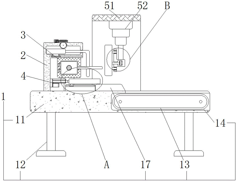
图1为本发明正视剖面结构示意图;Fig. 1 is the schematic diagram of the front view sectional structure of the present invention;
图2为本发明图1中A处放大结构示意图;Fig. 2 is a schematic diagram of enlarged structure at A place in Fig. 1 of the present invention;
图3为本发明图1中B处放大结构示意图;Fig. 3 is the schematic diagram of enlarged structure at B place in Fig. 1 of the present invention;
图4为本发明安装组件和拉伸组件连接侧视剖面结构示意图;Fig. 4 is a side view sectional structural schematic diagram of the connection between the mounting assembly and the tensioning assembly of the present invention;
图5为本发明图4中C处放大结构示意图;Fig. 5 is a schematic diagram of the enlarged structure at C in Fig. 4 of the present invention;
图6为本发明安装组件和挤压组件连接侧视剖面结构示意图;Fig. 6 is a side view sectional structural schematic diagram of the connection between the installation assembly and the extrusion assembly of the present invention;
图7为本发明安装组件俯视结构示意图;Fig. 7 is a schematic top view structural diagram of the mounting assembly of the present invention;
图8为本发明推动组件和拉伸组件连接整体结构示意图。Fig. 8 is a schematic diagram of the overall structure of the connection between the pushing component and the stretching component of the present invention.
图中:1、安装组件;11、安装座;12、固定支腿;13、输送带;14、防掉落边缘条;15、第一内置轴承;16、第一驱动电机;17、承接座;2、推动组件;21、固定安装架;22、活动杆;23、第一连接件;24、第一调节盘;25、联动轴杆;26、第二调节盘;27、第一调节杆;28、第二驱动电机;3、拉伸组件;31、外壳体;32、第三驱动电机;33、第二调节杆;34、第二内置轴承;35、活动滑杆;351、连接撑杆;4、输送组件;41、固定座;42、活动板;43、第二连接件;44、第一电动伸缩杆;5、挤压组件;51、外框架;52、第二电动伸缩杆;53、支撑架;54、盒体;55、第四驱动电机;56、第三调节盘;57、第四调节盘;58、第三内置轴承;59、柔性内齿压制带;591、自重抵压板。In the figure: 1. Installation component; 11. Mounting seat; 12. Fixed outrigger; 13. Conveyor belt; 14. Anti-drop edge strip; 15. First built-in bearing; 16. First driving motor; 17. Accepting seat ;2, pushing assembly; 21, fixed mounting frame; 22, movable rod; 23, first connector; 24, first adjusting disc; 25, linkage shaft; 26, second adjusting disc; 27, first adjusting rod ; 28, the second driving motor; 3, the stretching assembly; 31, the outer shell; 32, the third driving motor; 33, the second adjusting rod; 34, the second built-in bearing; 35, the movable slide bar; 351, the connecting support Rod; 4. Conveyor assembly; 41. Fixed seat; 42. Movable plate; 43. Second connector; 44. First electric telescopic rod; 5. Extrusion assembly; 51. Outer frame; 52. Second electric telescopic rod ; 53, support frame; 54, box body; 55, the fourth driving motor; 56, the third adjusting disc; 57, the fourth adjusting disc; 58, the third built-in bearing; Pressure plate.
具体实施方式Detailed ways
下面将结合本发明实施例中的附图,对本发明实施例中的技术方案进行清楚、完整地描述,显然,所描述的实施例仅仅是本发明一部分实施例,而不是全部的实施例。基于本发明中的实施例,本领域普通技术人员在没有做出创造性劳动前提下所获得的所有其他实施例,都属于本发明保护的范围。The following will clearly and completely describe the technical solutions in the embodiments of the present invention with reference to the accompanying drawings in the embodiments of the present invention. Obviously, the described embodiments are only some, not all, embodiments of the present invention. Based on the embodiments of the present invention, all other embodiments obtained by persons of ordinary skill in the art without making creative efforts belong to the protection scope of the present invention.
请参阅图1-8,本发明提供一种技术方案:一种防止内卷褶皱的薄膜电容器卷绕芯子加工用压扁装置,包括安装组件1还包括有安装座11,安装座11的下端固定安装有固定支腿12,安装座11的内部设置有输送带13,且输送带13的前后两侧均设置有防掉落边缘条14,输送带13和安装座11的连接处设置有第一内置轴承15,且输送带13的后端安装有位于安装座11内部的第一驱动电机16,安装座11的右端上表面设置有承接座17;Referring to Figs. 1-8, the present invention provides a technical solution: a flattening device for processing winding cores of film capacitors to prevent inward wrinkling, including a mounting
推动组件2推动组件2还包括有固定安装架21,固定安装架21的内部设置有活动杆22,且活动杆22的下端设置有与固定安装架21相连接的第一连接件23,活动杆22的前后两端上侧设置有第一调节盘24,且第一调节盘24的内端设置有联动轴杆25,联动轴杆25的中部设置有第二调节盘26,且第二调节盘26的上端连接有第一调节杆27,并且第一调节杆27的左端设置有位于固定安装架21上端的第一调节杆27;The
拉伸组件3拉伸组件3还包括有外壳体31,外壳体31固定安装在推动组件2的右端下侧,且外壳体31的后端安装有第三驱动电机32,第三驱动电机32的前端设置有第二调节杆33,且第二调节杆33和外壳体31的连接处设置有第二内置轴承34,第二内置轴承34的外侧设置有活动滑杆35,且活动滑杆35的右端设置有连接撑杆351;The stretching
输送组件4输送组件4还包括有固定座41,固定座41设置在拉伸组件3的下侧并与安装组件1相连接,且固定座41的上方设置有活动板42,活动板42的左端下侧设置有与固定座41相连接的第二连接件43,且第二连接件43的左端设置有与推动组件2相连接的第一电动伸缩杆44;The conveying
挤压组件5挤压组件5还包括有外框架51,外框架51设置在安装组件1的中部上表面,且外框架51的内部上侧安装有第二电动伸缩杆52,第二电动伸缩杆52的下端设置有支撑架53,且支撑架53的下端设置有盒体54,盒体54的内部后侧安装有第四驱动电机55,且第四驱动电机55的前端设置有第三调节盘56,第三调节盘56的外侧设置有第四调节盘57,且第四调节盘57和盒体54的连接处设置有第三内置轴承58,第四调节盘57的外侧设置有柔性内齿压制带59,第三调节盘56的下端设置有与柔性内齿压制带59内侧相贴合的自重抵压板591。
在使用该防止内卷褶皱的薄膜电容器卷绕芯子加工用压扁装置时,此装置由安装组件1、推动组件2、拉伸组件3、输送组件4和挤压组件5构成,首先将各个零件组装完成,然后将安装座11通过固定支腿12稳定的放置在地面上,具体的如图1、图2和图4中,将薄膜电容器卷绕芯子放置在连接撑杆351上,设置第二调节杆33通过第二内置轴承34在外壳体31上构成转动结构,能够在打开第三驱动电机32的时候带动第二调节杆33同步转动,配合第二调节杆33与活动滑杆35之间采用螺纹的方式相连接,且第二调节杆33的螺纹方向关于外壳体31的中心线前后呈相反设置,当转动第二调节杆33的时候,可以使套接在连接撑杆351上的薄膜电容器卷绕芯子进行拉伸,通过拉伸可以避免内卷褶皱。When using the film capacitor winding core processing flattening device for preventing inward wrinkling, the device is composed of a mounting
具体的如图1、图5和图8中,设置第一调节盘24通过焊接与联动轴杆25和第二调节盘26均构成一体化结构,且第二调节盘26与第一调节杆27之间采用啮合的方式相连接,能够在打开第二驱动电机28转动第一调节杆27的时候,在啮合连接的作用下带动第二调节盘26进行同步转动,配合连接撑杆351的右端贯穿于活动杆22的右端内部,且活动杆22通过第一连接件23在固定安装架21上构成卡合式滑动结构,能够在活动杆22左右移动的时候,将薄膜电容器卷绕芯子推动到承接座17上。Specifically, as shown in Fig. 1, Fig. 5 and Fig. 8, the
具体的如图3、图6和图7中,当拉伸过后的薄膜电容器卷绕芯子掉落到承接座17上的时候,此时打开外框架51内部上侧安装的第二电动伸缩杆52驱动支撑架53,设置支撑架53通过焊接与盒体54构成一体化结构,能够在支撑架53向下移动的时候,使柔性内齿压制带59在自重抵压板591的作用下对薄膜电容器卷绕芯子进行压扁操作,通过第三调节盘56和柔性内齿压制带59均与第四调节盘57之间采用啮合的方式相连接,且第四调节盘57通过第三内置轴承58在盒体54上构成转动结构,能够在打开第四驱动电机55转动第三调节盘56的时候,带动柔性内齿压制带59进行同步转动,达到了可以对薄膜电容器卷绕芯子进行压扁。Specifically as shown in Fig. 3, Fig. 6 and Fig. 7, when the stretched film capacitor winding core falls on the receiving
具体的如图1、图4和图6中,当薄膜电容器卷绕芯子推动到输送带13上,由于输送带13通过第一内置轴承15在安装座11上构成转动结构,能够在打开第一驱动电机16转动输送带13的时候,将输送带13上表面的薄膜电容器卷绕芯子滚动传送到收集箱内,进行统一收集,配合输送带13的前后两端外侧均设置有防掉落边缘条14,能够避免薄膜电容器卷绕芯子在输送过程中导致掉落。Specifically as shown in Fig. 1, Fig. 4 and Fig. 6, when the winding core of the film capacitor is pushed onto the
尽管已经示出和描述了本发明的实施例,对于本领域的普通技术人员而言,可以理解在不脱离本发明的原理和精神的情况下可以对这些实施例进行多种变化、修改、替换和变型,本发明的范围由所附权利要求及其等同物限定。Although the embodiments of the present invention have been shown and described, those skilled in the art can understand that various changes, modifications and substitutions can be made to these embodiments without departing from the principle and spirit of the present invention. and modifications, the scope of the invention is defined by the appended claims and their equivalents.
Claims (10)
Priority Applications (1)
| Application Number | Priority Date | Filing Date | Title |
|---|---|---|---|
| CN202210606779.6A CN115064396B (en) | 2022-05-31 | 2022-05-31 | A flattening device for processing winding cores of film capacitors to prevent inward wrinkling |
Applications Claiming Priority (1)
| Application Number | Priority Date | Filing Date | Title |
|---|---|---|---|
| CN202210606779.6A CN115064396B (en) | 2022-05-31 | 2022-05-31 | A flattening device for processing winding cores of film capacitors to prevent inward wrinkling |
Publications (2)
| Publication Number | Publication Date |
|---|---|
| CN115064396A CN115064396A (en) | 2022-09-16 |
| CN115064396B true CN115064396B (en) | 2023-06-09 |
Family
ID=83197801
Family Applications (1)
| Application Number | Title | Priority Date | Filing Date |
|---|---|---|---|
| CN202210606779.6A Active CN115064396B (en) | 2022-05-31 | 2022-05-31 | A flattening device for processing winding cores of film capacitors to prevent inward wrinkling |
Country Status (1)
| Country | Link |
|---|---|
| CN (1) | CN115064396B (en) |
Families Citing this family (1)
| Publication number | Priority date | Publication date | Assignee | Title |
|---|---|---|---|---|
| CN117711844B (en) * | 2024-02-04 | 2024-04-19 | 四川省科学城久信科技有限公司 | Film capacitor roll core flattening device |
Citations (3)
| Publication number | Priority date | Publication date | Assignee | Title |
|---|---|---|---|---|
| CN212648303U (en) * | 2020-08-12 | 2021-03-02 | 无锡先导智能装备股份有限公司 | Battery cell blanking device and winding equipment |
| CN112573259A (en) * | 2020-11-17 | 2021-03-30 | 安徽力幕新材料科技有限公司 | Aluminum foil roll supporting mechanism for lithium battery and using method thereof |
| CN114121508A (en) * | 2021-12-02 | 2022-03-01 | 常州晟威机电有限公司 | Finished product hot pressing mechanism |
Family Cites Families (2)
| Publication number | Priority date | Publication date | Assignee | Title |
|---|---|---|---|---|
| JP2004128333A (en) * | 2002-10-04 | 2004-04-22 | Shinko Electric Ind Co Ltd | Thin film capacitor device, its mounting module and manufacturing method |
| US7658556B2 (en) * | 2005-01-07 | 2010-02-09 | Joseph Johnson | Panoramic camera mount |
-
2022
- 2022-05-31 CN CN202210606779.6A patent/CN115064396B/en active Active
Patent Citations (3)
| Publication number | Priority date | Publication date | Assignee | Title |
|---|---|---|---|---|
| CN212648303U (en) * | 2020-08-12 | 2021-03-02 | 无锡先导智能装备股份有限公司 | Battery cell blanking device and winding equipment |
| CN112573259A (en) * | 2020-11-17 | 2021-03-30 | 安徽力幕新材料科技有限公司 | Aluminum foil roll supporting mechanism for lithium battery and using method thereof |
| CN114121508A (en) * | 2021-12-02 | 2022-03-01 | 常州晟威机电有限公司 | Finished product hot pressing mechanism |
Also Published As
| Publication number | Publication date |
|---|---|
| CN115064396A (en) | 2022-09-16 |
Similar Documents
| Publication | Publication Date | Title |
|---|---|---|
| CN115064396B (en) | A flattening device for processing winding cores of film capacitors to prevent inward wrinkling | |
| CN209001019U (en) | A kind of lithium manganate battery production pole piece cold press device | |
| CN113086704A (en) | Be used for carbon fiber preimpregnation material to roll up device | |
| Abdullah et al. | Photovoltaic properties of ZnO photoanode incorporating with CNTs for dye-sensitized solar cell application | |
| CN210884490U (en) | Winding mechanism for aluminum foil processing | |
| CN109511439A (en) | A kind of greenhouse solar protection devices | |
| CN221916656U (en) | Aluminum foil winding device capable of reducing fold generation | |
| CN209483167U (en) | A kind of solar energy film roller shutter | |
| CN215283364U (en) | Asphalt coiled material tectorial membrane closing device | |
| CN206790837U (en) | It is a kind of to be used for outdoor damp-proof electrical control cabinet | |
| CN214455591U (en) | A financial tax flattener | |
| CN116142544A (en) | A battery surface coating device for new energy vehicles | |
| CN211719973U (en) | A power box with moisture-proof and sun-proof function | |
| CN212661475U (en) | Apartment bed with adjustable width | |
| CN216671405U (en) | Leveling device is used in effectual condenser metallized film processing of flattening | |
| CN209219450U (en) | A new type of dining car | |
| CN210076482U (en) | A knead and twist device for tea processing | |
| CN207540231U (en) | A kind of electronic cooling-warming box of conveniently moving | |
| CN210929472U (en) | Tea leaf rolling machine capable of improving tea leaf quality | |
| CN215933382U (en) | High-tolerance-voltage high-capacitance capacitor element | |
| CN222447019U (en) | Coating equipment for producing high-heat-conductivity adhesive tape | |
| CN223632724U (en) | Protective film winding device | |
| CN221668695U (en) | Material receiving device for super capacitor winding machine | |
| CN214175869U (en) | Large-capacity filter capacitor | |
| CN220027594U (en) | Battery foil coating device |
Legal Events
| Date | Code | Title | Description |
|---|---|---|---|
| PB01 | Publication | ||
| PB01 | Publication | ||
| SE01 | Entry into force of request for substantive examination | ||
| SE01 | Entry into force of request for substantive examination | ||
| GR01 | Patent grant | ||
| GR01 | Patent grant | ||
| PE01 | Entry into force of the registration of the contract for pledge of patent right |
Denomination of invention: A flattening device for winding core processing of a thin film capacitor to prevent inner curling and wrinkling Granted publication date: 20230609 Pledgee: Jiangsu Yangzhou Rural Commercial Bank Co., Ltd. Huoqiao Branch Pledgor: YANGZHOU NISSEI ELECTRIC CO.,LTD. Registration number: Y2025980064813 |
|
| PE01 | Entry into force of the registration of the contract for pledge of patent right |