CN115063578A - Method and device for detecting and positioning target object in chip image and storage medium - Google Patents
Method and device for detecting and positioning target object in chip image and storage medium Download PDFInfo
- Publication number
- CN115063578A CN115063578A CN202210990214.2A CN202210990214A CN115063578A CN 115063578 A CN115063578 A CN 115063578A CN 202210990214 A CN202210990214 A CN 202210990214A CN 115063578 A CN115063578 A CN 115063578A
- Authority
- CN
- China
- Prior art keywords
- determining
- target object
- target
- shape
- image
- Prior art date
- Legal status (The legal status is an assumption and is not a legal conclusion. Google has not performed a legal analysis and makes no representation as to the accuracy of the status listed.)
- Granted
Links
Images


Classifications
-
- G—PHYSICS
- G06—COMPUTING OR CALCULATING; COUNTING
- G06V—IMAGE OR VIDEO RECOGNITION OR UNDERSTANDING
- G06V10/00—Arrangements for image or video recognition or understanding
- G06V10/20—Image preprocessing
- G06V10/22—Image preprocessing by selection of a specific region containing or referencing a pattern; Locating or processing of specific regions to guide the detection or recognition
-
- G—PHYSICS
- G06—COMPUTING OR CALCULATING; COUNTING
- G06V—IMAGE OR VIDEO RECOGNITION OR UNDERSTANDING
- G06V10/00—Arrangements for image or video recognition or understanding
- G06V10/20—Image preprocessing
- G06V10/255—Detecting or recognising potential candidate objects based on visual cues, e.g. shapes
-
- G—PHYSICS
- G06—COMPUTING OR CALCULATING; COUNTING
- G06V—IMAGE OR VIDEO RECOGNITION OR UNDERSTANDING
- G06V10/00—Arrangements for image or video recognition or understanding
- G06V10/40—Extraction of image or video features
- G06V10/44—Local feature extraction by analysis of parts of the pattern, e.g. by detecting edges, contours, loops, corners, strokes or intersections; Connectivity analysis, e.g. of connected components
- G06V10/457—Local feature extraction by analysis of parts of the pattern, e.g. by detecting edges, contours, loops, corners, strokes or intersections; Connectivity analysis, e.g. of connected components by analysing connectivity, e.g. edge linking, connected component analysis or slices
-
- G—PHYSICS
- G06—COMPUTING OR CALCULATING; COUNTING
- G06V—IMAGE OR VIDEO RECOGNITION OR UNDERSTANDING
- G06V10/00—Arrangements for image or video recognition or understanding
- G06V10/70—Arrangements for image or video recognition or understanding using pattern recognition or machine learning
- G06V10/762—Arrangements for image or video recognition or understanding using pattern recognition or machine learning using clustering, e.g. of similar faces in social networks
-
- G—PHYSICS
- G06—COMPUTING OR CALCULATING; COUNTING
- G06V—IMAGE OR VIDEO RECOGNITION OR UNDERSTANDING
- G06V10/00—Arrangements for image or video recognition or understanding
- G06V10/70—Arrangements for image or video recognition or understanding using pattern recognition or machine learning
- G06V10/764—Arrangements for image or video recognition or understanding using pattern recognition or machine learning using classification, e.g. of video objects
-
- G—PHYSICS
- G06—COMPUTING OR CALCULATING; COUNTING
- G06V—IMAGE OR VIDEO RECOGNITION OR UNDERSTANDING
- G06V2201/00—Indexing scheme relating to image or video recognition or understanding
- G06V2201/06—Recognition of objects for industrial automation
-
- G—PHYSICS
- G06—COMPUTING OR CALCULATING; COUNTING
- G06V—IMAGE OR VIDEO RECOGNITION OR UNDERSTANDING
- G06V2201/00—Indexing scheme relating to image or video recognition or understanding
- G06V2201/07—Target detection
Landscapes
- Engineering & Computer Science (AREA)
- Theoretical Computer Science (AREA)
- Physics & Mathematics (AREA)
- General Physics & Mathematics (AREA)
- Multimedia (AREA)
- Computer Vision & Pattern Recognition (AREA)
- Health & Medical Sciences (AREA)
- Artificial Intelligence (AREA)
- Computing Systems (AREA)
- Databases & Information Systems (AREA)
- Evolutionary Computation (AREA)
- General Health & Medical Sciences (AREA)
- Medical Informatics (AREA)
- Software Systems (AREA)
- Image Analysis (AREA)
Abstract
The invention discloses a method and a device for detecting and positioning a target object in a chip image and a storage medium. Wherein, the method comprises the following steps: acquiring an image to be identified of a chip to be detected; determining a plurality of target connected domains which accord with preset connected domain limiting conditions according to an image to be identified; determining the position information of a plurality of target objects in the image to be recognized according to the image to be recognized and a plurality of target connected domains; determining shape features of the target objects according to the position information of the target objects; carrying out shape classification on the shape features of the target objects to generate a plurality of groups of shape components; generating a shape attribute mask diagram according to the shape attributes of the plurality of groups of shape components; and determining the target object according to the shape attribute mask diagram. The invention solves the technical problems of complex operation and low detection accuracy rate caused by the need of determining the shape category in advance when detecting the bump welding area region in the chip image in the related technology.
Description
Technical Field
The invention relates to the field of image processing, in particular to a method and a device for detecting and positioning a target object in a chip image and a storage medium.
Background
With the development and technical requirements of semiconductor large-scale integrated circuit production and processing technology, chip detection equipment is produced. However, when the chip inspection apparatus in the related art inspects the chip image to determine the Bump Pad (Bump/Pad) area in the chip image, a user is required to determine a possible shape of the Bump Pad area in advance and then sequentially inspect the Bump Pad area. However, in the actual process of manufacturing chips on wafers, the bump welding areas in the chip images may generate various new shapes, which results in not only tedious operations but also low detection accuracy in the related art.
In view of the above problems, no effective solution has been proposed.
Disclosure of Invention
The embodiment of the invention provides a method, a device and a storage medium for detecting and positioning a target object in a chip image, which are used for at least solving the technical problems of complicated operation and low detection accuracy rate caused by the fact that the shape type needs to be determined in advance when a bump welding area region in the chip image is detected in the related technology.
According to an aspect of an embodiment of the present invention, a method for detecting and positioning a target object in a chip image is provided, including: acquiring an image to be identified of a chip to be detected; determining a plurality of target connected domains which accord with preset connected domain limiting conditions according to an image to be identified, wherein the target connected domains are corresponding regions of target objects in a connected domain set image; determining the position information of a plurality of target objects in the image to be recognized according to the image to be recognized and a plurality of target connected domains; determining shape features of the target objects according to the position information of the target objects; carrying out shape classification on the shape features of the target objects to generate a plurality of groups of shape components; generating a shape attribute mask diagram according to the shape attributes of the plurality of groups of shape components; and determining the target object according to the shape attribute mask diagram.
Optionally, the position information includes a barycentric position and a contour position of the target object; the step of determining shape features of the plurality of target objects according to the position information of the plurality of target objects includes: determining shape features of the plurality of target objects according to the position of the center of gravity and the position of the outline; the shape features comprise the distance between the contour point and the gravity center of the target object and the included angle between the reference direction and the connecting line between the gravity center of the target object and the contour point, and the contour point is a point located on the contour line of the target object.
Optionally, the step of determining the shape feature of the target object according to the position of the center of gravity and the position of the contour includes: determining a plurality of sampling points in the contour points of each target object; and determining the distance between the sampling point and the center of gravity of the target object and the included angle between the connecting line direction between the sampling point and the center of gravity of the target object and the reference direction according to the contour position and the center of gravity position, wherein the connecting line direction is the direction in which the center of gravity points to the sampling point, and the contour position comprises the position of the sampling point.
Optionally, the step of determining a plurality of sampling points in the contour points of each target object includes: determining sampling step distances, wherein the sampling step distances are included angles of connecting lines of two adjacent sampling points and the center of gravity of the target object, and the connecting line direction of the connecting lines points to the sampling points from the reference points; determining a sampling direction, wherein the sampling direction comprises a clockwise direction or a counterclockwise direction; and determining a plurality of sampling points from the contour points according to the sampling direction and the sampling step distance.
Optionally, the step of determining the distance between the sampling point and the center of gravity of the target object comprises: establishing a barycentric plane coordinate system by taking a point corresponding to the barycentric coordinate as an origin; determining a sampling coordinate value of a sampling point in a gravity center plane coordinate system; and determining the distance between the sampling point and the reference point according to the sampling coordinate value.
Optionally, the step of determining a plurality of target connected domains meeting a preset connected domain limiting condition according to the image to be recognized includes: determining a gray threshold; carrying out binarization processing on an image to be identified according to a gray threshold value to obtain a connected domain set image; and determining a plurality of target connected domains which accord with preset connected domain limiting conditions from the connected domain set image.
Optionally, the step of determining the position information of the target object in the image to be recognized according to the image to be recognized and the plurality of target connected domains includes: determining coordinate values of pixel points in the target object in a first plane coordinate system according to the target connected domain, wherein the first plane coordinate system is a coordinate system established in the image to be recognized; determining the gray value of a pixel point; determining a gravity center position according to the gray value of the pixel point and the coordinate value of the pixel point, wherein the gravity center position comprises the coordinate value of the gravity center of the target object in a first plane coordinate system; and determining the contour position according to the gravity center position.
Optionally, the step of determining the contour position according to the gravity center position comprises: determining bounding box information of a target connected domain; and determining the contour position according to the bounding box information and the gravity center of the target object, wherein the contour position comprises contour coordinate values of the contour point in the first plane coordinate system.
Optionally, the step of determining the contour position according to the bounding box information and the center of gravity of the target object includes: determining the value range of the contour coordinate value according to the information of the boundary box; and determining the coordinate value of the maximum gradient value point in the preset direction in the first plane coordinate system by taking the gravity center of the target object as a reference point, and taking the coordinate value of the maximum gradient value point as a contour coordinate value in the preset direction, wherein the contour coordinate value is positioned in the range of the contour coordinate value.
Optionally, the preset connected component limitation condition includes at least one of: the width value range of the boundary box corresponding to the connected domain, the height value range of the boundary box, the width-to-height ratio value range of the boundary box, and the value range of the ratio of the area of the connected domain to the area of the boundary box.
Optionally, the step of classifying the shape of the shape features of the plurality of target objects to generate a plurality of groups of shape components includes: determining a target shape type label, wherein the target shape type label is a shape type label preset by a target object; and classifying the target object according to the target shape type label and the shape characteristic of the target object to obtain a plurality of groups of shape components.
According to another aspect of the embodiments of the present invention, there is also provided a device for detecting and positioning a target object in a chip image, including: the acquisition module is used for acquiring an image to be identified of the chip to be detected; the target connected domain determining module is used for determining a plurality of target connected domains which accord with the preset connected domain limiting conditions according to the image to be identified, and the target connected domains are corresponding regions of the target object in the connected domain set image; the position information determining module is used for determining the position information of a plurality of target objects in the image to be identified according to the image to be identified and the plurality of target connected domains; the shape characteristic determining module is used for determining the shape characteristics of the target objects according to the position information of the target objects; the shape classification module is used for carrying out shape classification on the shape characteristics of a plurality of target objects to generate a plurality of groups of shape components; the shape attribute mask diagram generating module is used for generating a shape attribute mask diagram according to the shape attributes of the plurality of groups of shape components; and the target object determining module is used for determining the target object according to the shape attribute mask diagram.
According to another aspect of the embodiments of the present invention, a non-volatile storage medium is further provided, where the non-volatile storage medium includes a stored program, and when the program runs, a device in which the non-volatile storage medium is located is controlled to execute the target object detection and positioning method in the chip image.
According to another aspect of the embodiments of the present invention, an electronic device is further provided, where the electronic device includes a processor, and the processor is configured to execute a program, where the program executes a method for detecting and locating a target object in a chip image during running.
In the embodiment of the invention, the method comprises the steps of acquiring an image to be identified of a chip to be detected; determining a plurality of target connected domains which accord with a preset connected domain limiting condition according to an image to be identified, wherein the target connected domains are corresponding regions of a target object in a connected domain set image; determining the position information of a plurality of target objects in the image to be recognized according to the image to be recognized and a plurality of target connected domains; determining shape features of the target objects according to the position information of the target objects; carrying out shape classification on the shape features of the target objects to generate a plurality of groups of shape components; generating a shape attribute mask diagram according to the shape attributes of the plurality of groups of shape components; the method for determining the target object according to the shape attribute mask image achieves the purpose of determining the position information of the target object in the image to be identified by screening the connected domain, thereby achieving the technical effects of identifying the target object and determining the position information of the target object in the image to be identified without determining the possible shape type of the target object in advance, and further solving the technical problems of complex operation and low detection accuracy rate caused by the fact that the shape type needs to be determined in advance when the bump welding area in the chip image is detected in the related technology.
Drawings
The accompanying drawings, which are included to provide a further understanding of the invention and are incorporated in and constitute a part of this application, illustrate embodiment(s) of the invention and together with the description serve to explain the invention without limiting the invention. In the drawings:
fig. 1 is a schematic flowchart of a method for detecting and positioning a target object in a chip image according to an embodiment of the present invention;
FIG. 2 is a schematic diagram of a target object in an image to be recognized and a binarized image according to an embodiment of the present invention;
FIG. 3 is a schematic diagram of a connected domain collection image provided according to an embodiment of the invention;
FIG. 4 is a schematic diagram of a connected domain and a bounding box corresponding to the connected domain according to an embodiment of the present invention;
fig. 5 is a flowchart illustrating a method for determining a shape feature of a target object according to an embodiment of the present invention;
fig. 6 is a schematic flowchart of a method for determining a contour position of a target object according to an embodiment of the present invention;
FIG. 7 is a flowchart illustrating another method for determining a contour position of a target object according to an embodiment of the present invention;
FIG. 8 is a schematic flowchart of a method for determining a contour position of a target object according to an embodiment of the present invention;
FIG. 9 is a diagram illustrating a connected domain and a target object according to an embodiment of the present invention;
FIG. 10 is a schematic diagram illustrating a method for determining a contour of an image area of a bump welding area according to an embodiment of the present invention;
FIG. 11 is a flow chart illustrating a method for generating shape components according to an embodiment of the present invention;
FIG. 12 is a schematic diagram illustrating shape feature sampling of a target object according to an embodiment of the present invention;
FIG. 13 is a schematic diagram illustrating shape characteristics of a target object according to an embodiment of the present invention;
FIG. 14 is a flowchart illustrating a method for determining a position and a shape of a target object according to an embodiment of the present invention;
fig. 15 is a schematic structural diagram of an apparatus for detecting and positioning a target object in a chip image according to an embodiment of the present invention;
fig. 16 is a schematic structural diagram of an apparatus for detecting and positioning a target object in a chip image according to an embodiment of the present invention;
fig. 17 is a schematic structural diagram of a computer device provided in an embodiment of the present invention.
Detailed Description
At present, in the actual process manufacturing process of a chip, Bump/Pad (Bump welding area) with increasingly complex shapes and the manufacturing precision are continuously increased, the related technology cannot meet the requirement that new shapes can appear at any time, so that the compatibility of an algorithm and software is poor, and particularly when a scene with more components on a Die (chip) is faced, because the related technology needs to firstly specify the shape category of the Bump/Pad and then search all Bump/Pad with the same shape type in an image in a template matching mode. Although this method can ensure the recognition accuracy of the Bump/Pad of the known shape type, the operation is complicated, especially when there are many types of Bump/pads (such as circle, square, ellipse, regular hexagon, etc.) in the image.
In order to solve the above problems, the present application provides a method for detecting and positioning a target object in a chip image through a connected domain, which can position Bump/Pad in the image under the condition that the image type of the Bump/Pad in the target image is not determined, determine the shape type of the Bump/Pad in the image, determine multiple groups of shape components, generate a shape attribute mask diagram, and position the Bump/Pad according to the shape attribute mask diagram.
In order to make the technical solutions of the present invention better understood, the technical solutions in the embodiments of the present invention will be clearly and completely described below with reference to the drawings in the embodiments of the present invention, and it is obvious that the described embodiments are only a part of the embodiments of the present invention, and not all of the embodiments. All other embodiments, which can be derived by a person skilled in the art from the embodiments given herein without making any creative effort, shall fall within the protection scope of the present invention.
It should be noted that the terms "first," "second," and the like in the description and claims of the present invention and in the drawings described above are used for distinguishing between similar elements and not necessarily for describing a particular sequential or chronological order. It is to be understood that the data so used is interchangeable under appropriate circumstances such that the embodiments of the invention described herein are capable of operation in sequences other than those illustrated or described herein. Furthermore, the terms "comprises," "comprising," and "having," and any variations thereof, are intended to cover a non-exclusive inclusion, such that a process, method, system, article, or apparatus that comprises a list of steps or elements is not necessarily limited to those steps or elements expressly listed, but may include other steps or elements not expressly listed or inherent to such process, method, article, or apparatus.
Example 1
In accordance with an embodiment of the present invention, there is provided an embodiment of a method for detecting and locating a target object in a chip image, where the steps illustrated in the flowchart of the drawings may be performed in a computer system such as a set of computer executable instructions, and where a logical order is illustrated in the flowchart, in some cases, the steps illustrated or described may be performed in an order different than that illustrated or described herein.
Fig. 1 is a method for detecting and positioning a target object in a chip image according to an embodiment of the present invention, as shown in fig. 1, the method includes the following steps:
step S102, acquiring an image to be identified of a chip to be detected;
in the solution provided in step S102, the image to be identified of the chip to be detected is a grayscale image of the chip to be detected, and can be acquired by an image acquisition module integrated in the testing device, such as a camera.
Step S104, determining a plurality of target connected domains which accord with preset connected domain limiting conditions according to the image to be identified, wherein the target connected domains are corresponding regions of target objects in a connected domain set image;
in the scheme provided in step S104, when determining a target connected domain according to an image to be recognized, first, a connected domain set image needs to be determined according to the image to be recognized. Since the gray values of the target object in the chip image are the same or have smaller differences, when the connected domain set image is determined from the image to be recognized, a gray threshold value can be set first, and then binarization processing is performed on the image to be recognized according to the gray threshold value, so that the connected domain set image corresponding to the image to be recognized as shown in fig. 3 is obtained. The target connected domain corresponding to the target object in the connected domain set image and the target object in the image to be recognized are shown in fig. 2.
Specifically, the connected component set image has a white portion and a black portion, wherein the white portion is a connected component, such as the plurality of connected components represented in fig. 9 and 2. In an embodiment, with continued reference to fig. 2, the shapes of the connected components are square, L-shaped, vertical bar, and rectangle, but the shapes of the connected components are not limited thereto.
It should be noted that, in some embodiments, the target object may be an image area corresponding to a Bump welding area (Bump/Pad) in the chip to be detected in the image to be recognized, that is, an image area of the Bump welding area in the image to be recognized.
It should be noted that, in the following embodiments, the number of the target connected component and the number of the target object are both multiple, and various parameters of each target connected component and each target object, such as the target connected component bounding box information, the target object contour position, the target object center point position, the barycentric coordinate, and the like, may be determined. And the target connected domain and the target object are in one-to-one correspondence. Optionally, the target object contour position includes a coordinate value of a contour point on the target object contour, and the target object center position includes a coordinate value of the target object center.
As an alternative embodiment, when setting the grayscale threshold, since different target objects usually have a certain interval, one grayscale threshold may be set for the whole image, or the image may be divided into a plurality of sub-regions according to the distribution of the grayscale values in the image, and then the corresponding grayscale threshold is set for each sub-region. By setting the corresponding gray threshold value for each sub-region, the technical effect that each connected domain can be accurately identified in the connected domain set image even if a plurality of target objects with larger gray value difference exist in the image to be identified is achieved.
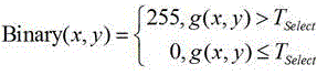
Specifically, the binarization process is as follows, where the following formula (x, y) refers to any one pixel point in the image to be recognized, g (x, y) is a gray value of the pixel point in the image to be recognized, and T is a gray value of the pixel point in the image to be recognized select For the gray threshold corresponding to the pixel point, Binary (x, y) is the gray value of the pixel point corresponding to the pixel point in the connected domain set image, and the value is 255 or 0. The binarization formula is as follows:
as an alternative implementation, before the technical solution provided in step S102 is executed, image filtering and contrast enhancement may be performed on the image to be recognized. The formula when contrast enhancement is performed is as follows:
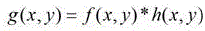
in the above formula, the first and second carbon atoms are, the original image is represented by a digital image,
 representing the image after the contrast enhancement,
 is a spatial transfer function.
In the technical solution provided in step S104, after the connected domain set image shown in fig. 3 is acquired, as can be seen from fig. 3, the connected domain included in the connected domain set image is not completely the connected domain corresponding to the target object, for example, the interference type 1 in fig. 3, where the connected domain shown in the interference type 1 is the connected domain belonging to RDL (Redistribution layer). In order to remove the connected domains corresponding to the non-target objects, a connected domain limiting condition may be set to screen the connected domains, so as to obtain at least one target connected domain and a bounding box corresponding to each target connected domain. In addition, connected domains corresponding to target objects with different shapes are also provided in fig. 3. For example, type 1 in fig. 3 is a connected domain type corresponding to a circular target object, and type 2 is a connected domain type corresponding to a capsule-shaped target object.
In addition, fig. 3 also shows a schematic diagram of a circumscribed rectangle of the connected component corresponding to different target objects. It can be seen that the circumscribed rectangles of the connected domains corresponding to the target objects of different shapes have different sizes, so that on one hand, the sides of the circumscribed rectangles can be used to screen all the connected domains corresponding to the target objects in fig. 3, for example, in the figure, the circumscribed rectangles of the circular target object and the capsule-type target object both fall in the gray color region (size) shown in the figure, and on the other hand, decision conditions, such as the area ratio value range of the connected domain, can be increased, and connected domains not belonging to Bump/pad, such as the interference type 1 (which belongs to the line), can also be filtered.
Specifically, the connected domain is an image region determined in a connected domain set image, wherein the connected domain set image is an image determined after the binarization processing is performed on the image to be identified. The target connected domain corresponding to the target object in the image to be recognized refers to a connected domain with the same position in the connected domain set image as the target object in the image to be recognized.
Specifically, for any target connected domain pixel point in a plurality of target connected domains, a target object pixel point corresponding to the any target connected domain pixel point exists in a target object, so that the row and column number of the any target connected domain pixel point in a connected domain set image is the same as the row and column number of the target object pixel point in an image to be identified.
As an optional implementation manner, the preset connected component limitation condition includes at least one of the following: the width value range and the height value range of the connected domain, the width-to-height ratio value range of the connected domain and the area-to-area ratio value range of the connected domain, wherein the width value range of the connected domain is the width value range of a boundary frame corresponding to the connected domain, the height value range of the connected domain is the height value range of the boundary frame, the width-to-height ratio value range of the connected domain is the width-to-height ratio value range of the boundary frame, and the area-to-area ratio value range of the connected domain is the value range of the ratio of the area of the connected domain to the area of the boundary frame. Specifically, the specific definition of the width and height of the connected component and the bounding box corresponding to the connected component can refer to the schematic diagram of the connected component and the bounding box corresponding to the connected component shown in fig. 4. It should be noted that the preset connected domain limiting conditions can be preset by technicians to brush out a target connected domain meeting the conditions, so that the interference connected domain is removed, the screening process is saved, the bump welding area with any shape is compatible, and the positioning accuracy of the connected domain is improved.
Step S106, determining the position information of a plurality of target objects in the image to be recognized according to the image to be recognized and a plurality of target connected domains;
in the technical solution provided in step S106, the position information of the target object in the image to be recognized may be determined according to the position information of the target connected component in the connected component set image. The position information of the target connected domain in the connected domain set image comprises the position information of the target connected domain and the position information of a boundary frame corresponding to the target connected domain.
Step S108, determining the shape characteristics of a plurality of target objects according to the position information of the plurality of target objects;
it should be noted that, in the technical solution provided in step S108, determining the shape features of the plurality of target objects according to the position information of the plurality of target objects means that, in the case that there are a plurality of target objects, the shape features of each of the plurality of target objects are determined according to the position information of the target object. For example, when the target object a and the target object B exist, the technical solution provided in step S108 determines the shape feature of the target object a according to the position information of the target object a and determines the shape feature of the target object B according to the position information of the target object B, respectively.
Step S110, carrying out shape classification on shape features of a plurality of target objects to generate a plurality of groups of shape components;
in the technical solution provided in step S110, the shape features of the plurality of target objects in each group of shape components are the same, and the shape components refer to a set of mathematically and geometrically identical shape features.
Step S112, generating a shape attribute mask diagram according to the shape attributes of the plurality of groups of shape components;
in the technical solution provided in step S112, it should be noted that the shapes of the target objects in the same shape component are all the same; for example: the shape component 1 includes a plurality of target objects of the same shape, such as target objects all of which are circular, target objects all of which are square in the shape component 2, and the like. In addition, the shape attribute mask map may include any combination of shape components. For example, the combination mode can be changed according to the user requirement to obtain the shape attribute mask diagram desired by the user.
Step S114, determining the target object according to the shape attribute mask diagram.
In the scheme provided in step S106, the position information of the target object in the image to be recognized includes a barycentric position and a contour position. The step of determining shape features of the plurality of target objects according to the position information of the plurality of target objects includes: determining shape features of the plurality of target objects according to the position of the center of gravity and the position of the outline; the shape features comprise the distance between the contour point and the gravity center of the target object and the included angle between the reference direction and the connecting line between the gravity center of the target object and the contour point, and the contour point is a point located on the contour line of the target object.
It should be noted that the center of gravity in the embodiment of the present application can be regarded as the energy center. Specifically, taking a target object as an example, the method for determining the center of gravity of the target object is to regard the gray value of each pixel point in the target object as the quality of the pixel point, and then determine the coordinate of the center of gravity according to the quality of each pixel point and the coordinate of the pixel point in the first plane coordinate system. The gravity center definition and calculation method of the target connected domain are also the same. The first plane coordinate system is a plane coordinate system established in the image to be identified. Specifically, the first planar coordinate system may be a planar rectangular coordinate system. In addition, in order to reduce the amount of calculation, in the case where the first planar coordinate system is a planar rectangular coordinate system, two coordinate axes of the first planar coordinate system may be set to be parallel to the length and width of the image to be recognized, respectively.
In some embodiments of the present application, a method for determining shape features of a plurality of target objects based on a center of gravity position and a contour position is shown in fig. 5, comprising the steps of:
step S502, determining a plurality of sampling points in the contour point of each target object;
step S504, determining the distance between the sampling point and the center of gravity of the target object and the included angle between the connecting line direction between the sampling point and the center of gravity of the target object and the reference direction according to the contour position and the center of gravity position, wherein the connecting line direction is the direction in which the center of gravity points to the sampling point, and the contour position comprises the sampling point position.
Specifically, a specific manner of determining the shape characteristics of the bump land image area by the sampling points described above is shown in fig. 12. From FIG. 12It can be seen that, when determining the distance between the sampling point and the reference point, a barycentric plane coordinate system may be established with the barycenter as an origin, where the barycentric coordinate system may be a rectangular plane coordinate system as shown in fig. 12, or may be another coordinate system that may represent the distance between the sampling point and the reference point. And then calculating the distance between the sampling point and the reference point according to the coordinate value of the sampling point in the barycentric plane coordinate system. In addition, the positive X-axis direction in the barycentric plane coordinate system may be set as the reference direction. Wherein point P in FIG. 12 0 、P 1 、P 2 ......P k ......P n Representing sample points on the contour of each target object. It will be understood that the points in the figures are for illustration purposes only and are not limiting as to the location and number of sample points.
Alternatively, in the case where the second planar coordinate system is a rectangular planar coordinate system, in order to simplify the calculation, two coordinate axes of the second planar coordinate system may be set to be parallel to the width and height of the bounding box, respectively, or two coordinate axes of the second planar coordinate system may be set to be parallel to two coordinate axes of the first coordinate system, respectively.
As an alternative implementation, when determining the sampling point, a plurality of sampling directions may be determined, and then a point of the contour point, which is the same as a connecting line direction between the reference point and the contour point and the sampling direction, is determined as the sampling point, where the connecting line direction between the contour point and the reference point is from the reference point to the sampling point. Specifically, firstly, determining a sampling step pitch, wherein the sampling step pitch is an included angle between connecting lines of two adjacent sampling points and a reference point, and the connecting line direction of the connecting lines is that the reference point points to the sampling points; then, a sampling direction is determined, wherein the sampling direction comprises one of: clockwise or counterclockwise; and finally, determining a plurality of sampling points from the contour points according to the sampling direction and the sampling step distance.
In the above manner, the target object can be described by the following two formulas:
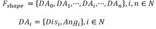
wherein n represents the number of samples, refers to the set of the distance from the sampling point Pi to the center of gravity of the connected component and the sampling angle, specifically,
 the distance is represented as a function of time,
 indicating an angle.
In some embodiments of the present application, the sampling points may also be displayed in a planar rectangular coordinate system with the angle as abscissa and the distance as ordinate, as shown in fig. 13. Wherein point P in FIG. 13 0 、P 1 、P 2 ......P k ......P n Representing sample points on the contour of each target object. It will be understood that the points in the figures are for illustration purposes only and are not limiting as to the location and number of sample points.
In addition, fig. 13 also provides a method for determining the shape characteristics of the target object according to the sampling points. Specifically, in the method provided in fig. 13, after the angle and the distance corresponding to each sampling point in the multiple sampling points are determined, the coordinate point corresponding to each sampling point is drawn in the right coordinate graph, and the coordinate points are fitted to obtain a fitting curve. The possible shape of the target object can be roughly determined from the fitted curve. For example, when the fitted curve is a straight line parallel to the X-axis, it indicates that the distances from the sampling points at different angles to the center of gravity are the same, and it indicates that the target object is likely to be a circle. And when the fitted curve of the target object is a periodically transformed curve and the transformation period is pi/2, the target object can be considered as a graph with two mutually perpendicular symmetry axes.
In the fitting, a point having a large difference from the other coordinate points is discarded, as shown in fig. 13, which shows a hollow point in the right-side coordinate when the target object is a circle.
It can be seen that by representing target objects as a set of sampling points to reference points' distances and sampling angles, the shape characteristics of each target object can be more accurately described. In addition, in the embodiment of the present application, the center of gravity of the target object is determined according to the target connected domain, and the center of gravity is used as the origin, and the contour edge point of the target object is sampled by 360 degrees, so that the description of the shape is expressed as a set formed by the distances from the n contour sampling points to the origin and the sampling angles. By adopting the method to describe the shape of the target object, the shape of any target object can be compatible, and the compatibility and the descriptiveness in the process of determining the shape of the target object are improved.
In some embodiments of the present application, after the shape feature of each target object is determined, a target shape type tag may also be determined, where the target shape type tag is a shape type tag preset for the target object; and classifying the target object according to the target shape type label and the shape characteristic of the target object.
Under the condition that no target shape type label exists, the target objects can be clustered according to the shape characteristics of the target objects in the scheme provided by the application, so that a target object set with different shape characteristics is obtained, and the clustering result is displayed for the target objects.
Specifically, when the target object provides the shape type label, a supervised learning classification method, such as an SVM, Boosting, a BP neural network, etc., may be used to classify the shape region of the bump weld, and when the target object does not provide the shape type label, a conventional clustering method, such as K clustering, may be used to cluster different shapes.
In the clustering process, the data information of the shapes in the same category can be updated according to the shape characteristics of the target object, and after the clustering is finished, the clustering result is displayed on the target object, including displaying all shape types on the target object. After the target object selects a certain shape type, the position information of all target objects in the image to be recognized under the shape type can be shown to the target object.
It can be seen that, in the embodiment of the present application, all the target connected domains corresponding to the target object are screened out through binarization of the image to be recognized, the boundary frame of each target connected domain is determined, the contour of the target object is determined through the boundary frame and the target connected domain, and all the shape categories of the target object in the image to be recognized can be obtained by combining the shape description mode and any clustering algorithm provided in the embodiment.
In the technical solution provided in step S502, a plurality of sampling points may be determined from the contour points of each target object by: determining sampling step distances, wherein the sampling step distances are included angles of connecting lines of two adjacent sampling points and the center of gravity of the target object, and the connecting line direction of the connecting lines points to the sampling points from the reference points; determining a sampling direction, wherein the sampling direction comprises a clockwise direction or a counterclockwise direction; and determining a plurality of sampling points from the contour points according to the sampling direction and the sampling step distance.
In the technical solution provided in step S106, when determining the position information of the plurality of target objects in the image to be recognized according to the image to be recognized and the plurality of target connected domains, a positioning method as shown in fig. 6 may also be adopted, and the specific steps are as follows:
step S602, determining coordinate values of pixel points in a target object in a first plane coordinate system according to a target connected domain, wherein the first plane coordinate system is a coordinate system established in an image to be identified;
step S604, determining the gray value of the pixel point;
step S606, determining a gravity center position according to the gray value of the pixel point and the coordinate value of the pixel point, wherein the gravity center position comprises the coordinate value of the gravity center of the target object in a first plane coordinate system;
in step S608, the contour position is determined based on the center of gravity position.
Specifically, in the technical solution provided in step S606, a specific formula for determining the center of gravity of the target object according to the gray value and the coordinate value of the pixel point is as follows:
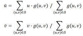
wherein Is a first coordinate value of the center of gravity in a first planar coordinate system,
 is a second coordinate value of the center of gravity in the first planar coordinate system,
 representing coordinate values of
 And Ω represents all the pixels in the target object.
Through the formula, the barycentric coordinates corresponding to each target object can be obtained and recorded as 。
。
In the scheme provided in step S608, the contour position includes coordinate values of contour points in the first plane coordinate system, where the contour points are points located on the contour line of the target object. Specifically, as shown in fig. 7, the method for determining the position of the contour according to the position of the center of gravity includes the following steps:
step S702, determining the bounding box information of the target connected domain;
step S704, determining a contour position according to the bounding box information and the gravity center of the target object, wherein the contour position comprises contour coordinate values of the contour point in the first plane coordinate system.
In the scheme provided in step S702, the bounding box information of the target connected domain includes coordinate values of the bounding box of the target connected domain in a second planar coordinate system, where the second planar coordinate system is a rectangular planar coordinate system established in the connected domain set image, and the establishment rules of the second planar coordinate system and the first planar coordinate system are the same. For example, the second planar coordinate system and the first planar coordinate system each have a point at the upper left corner of the image as an origin, a horizontal right direction as a positive X-axis direction, a numerical value downward as a positive Y-axis direction, and the unit lengths in the two coordinate systems are the same. Therefore, the coordinate value of the pixel point in the target connected domain in the second plane coordinate system can be considered to be equal to the coordinate value of the corresponding pixel point in the target object in the first plane coordinate system.
After the boundary frame information of the target connected domain is determined, the boundary frame information of the boundary frame corresponding to the target object can be determined in the image to be identified according to the boundary frame information. Specifically, the coordinate value of any point in the bounding box of the target connected domain in the second planar coordinate system is the same as the coordinate value of the corresponding point in the bounding box of the target object in the first planar coordinate system.
In the technical solution provided in step S704, a specific manner of determining the contour position according to the bounding box information and the center of gravity of the target object is shown in fig. 8, and includes the following steps:
step S802, determining a value range of the contour coordinate value according to the information of the boundary box;
step S804, determining a coordinate value of the maximum gradient point in the preset direction in the first planar coordinate system with the center of gravity of the target object as a reference point, and using the coordinate value of the maximum gradient point as a contour coordinate value in the preset direction, wherein the contour coordinate value is located within a value range of the contour coordinate value.
In the scheme provided in step S802, determining the value range of the outline coordinate value according to the information of the bounding box means determining the value range of the outline coordinate value according to the coordinate value of the bounding box. Specifically, a first bounding box corresponding to the target object is determined in the image to be recognized according to the bounding box information of the target connected domain, wherein the first bounding box is obtained by mapping the bounding box of the target connected domain into the image to be recognized, and therefore the size and the shape of the first bounding box are the same as those of the bounding box of the target connected domain. After the first bounding box is obtained, a second bounding box may be determined based on the first bounding box, as shown in FIG. 10. The second bounding box is obtained by scaling on the basis of the first bounding box, and the specific scaling factor can be set by the user. Where the gray frame in fig. 10 is the first bounding box and the black frame is the second bounding box, the contour points are in the region between the first bounding box and the second bounding box. Therefore, the value range of the contour coordinate value of the contour point is determined through the first boundary box and the second boundary box, and the calculation amount during contour point determination is reduced.
In the technical solution provided in step S804, the preset direction is an arbitrary direction pointing from the reference point to the contour point.
The resulting contour region may be identified as a set of contour points using the following formula:

in the above formula The contour points determined in each direction by the gradient maxima are indicated, also referred to as sampling points, and n is the number of sampling points.
In the technical solution provided in step S110, a specific manner of classifying the shape features of the plurality of target objects and generating the multi-shape component is shown in fig. 11, and includes the following steps:
step S1102, determining a target shape type label, wherein the target shape type label is a shape type label preset by a target object;
step S1104, classifying the target object according to the target shape type tag and the shape feature of the target object to obtain a plurality of groups of shape components.
In some embodiments of the present application, the target object contour position comprises coordinate values of contour points in the first planar coordinate system, the contour points being points on the target object contour line. The following method may be adopted when determining the position information of the target object in the image to be recognized according to the barycentric coordinates and the bounding box information: determining the value range of the contour coordinate value of the contour point in a plane coordinate system according to the information of the bounding box; as shown in fig. 10, the coordinate values of the point having the largest gradient value in each direction in the first planar coordinate system are determined using the point corresponding to the barycentric coordinate value as a reference point, and the coordinate value of the point having the largest gradient value is set as the contour coordinate value in each direction. The area between the black frame and the gray frame in fig. 10 is the outline area of the target object.
Acquiring an image to be identified of a chip to be detected; determining a plurality of target connected domains which accord with preset connected domain limiting conditions according to an image to be identified, wherein the target connected domains are corresponding regions of target objects in a connected domain set image; determining the position information of a plurality of target objects in the image to be recognized according to the image to be recognized and a plurality of target connected domains; determining shape features of the target objects according to the position information of the target objects; carrying out shape classification according to the shape characteristics of a plurality of target objects to generate a plurality of groups of shape components; generating a shape attribute mask diagram according to the shape attributes of the plurality of groups of shape components; the method for determining the target object according to the shape attribute mask image achieves the purpose of determining the position information of the target object in the image to be identified by screening the connected domain, thereby achieving the technical effects of identifying the target object and determining the position information of the target object in the image to be identified without determining the possible shape type of the target object in advance, and further solving the technical problems of complex operation and low detection accuracy rate caused by the fact that the shape type needs to be determined in advance when the bump welding area in the chip image is detected in the related technology.
In addition, the method for detecting and positioning the target object in the chip image provided by the embodiment of the application can be well adapted to the situation that the target object with a new shape type may appear in the chip image in the current chip production and manufacturing process, and various shapes of the target object can be found out at one time by a method of positioning in classification first, so that the complexity of user operation is greatly reduced, and the efficiency of creating a recipe program menu during bump/pad detection on a chip is improved. The user does not need to specify the shape category empirically, and the complexity of operation and positioning when the number of component elements in the image to be recognized is large is solved.
In addition, in the process of searching the boundary of the target object according to the connected domain, the relevance between the connected domain and the contour of the target object is reasonably used, the search boundary of the contour is set on the basis, and the stability and reliability of the process of determining the target object are improved.
There is also provided, in accordance with an embodiment of the present invention, a method embodiment of a method for target object location and shape determination, it being noted that the steps illustrated in the flowchart of the accompanying drawings may be performed in a computer system such as a set of computer-executable instructions and that, although a logical order is illustrated in the flowchart, in some cases, the steps illustrated or described may be performed in an order different than here.
Fig. 14 is a method for determining the location and shape of a target object according to an embodiment of the present invention, as shown in fig. 14, the method including the steps of:
step S1402, preprocessing an image to be recognized;
in the technical solution provided in step S1402, processing the image to be recognized includes performing contrast enhancement and image filtering on the image to be recognized.
Step S1404, performing binary segmentation on the processed image to be recognized, so as to determine a connected domain corresponding to the target object in the image to be recognized;
in the technical solution provided in step S1404, it should be noted that the connected component determined after binary segmentation is not all the connected components corresponding to the target object, and therefore, it is also necessary to set a corresponding connected component screening condition, so that only the connected component corresponding to the target object is retained.
Step S1406, determining the position information of the target object in the image to be identified according to the connected domain;
specifically, determining the position information of the target object in the image to be recognized includes determining the position information of a center point of the target object in the image to be recognized and the position information of an edge of the target object in the image to be recognized.
Step S1408, determining a shape feature of the target object;
step S1410, classifying the shape features of the target object, and displaying the classification result to the user.
Example 2
According to an embodiment of the invention, an embodiment of a device for detecting and positioning a target object in a chip image is provided. Fig. 15 is a schematic structural diagram of a target object locating device according to an embodiment of the present invention. As shown in fig. 15, the apparatus includes: the acquiring module 150 is used for acquiring an image to be identified of the chip to be detected; a target connected domain determining module 152, configured to determine, according to the image to be identified, a plurality of target connected domains that meet a preset connected domain limiting condition, where a target connected domain is a corresponding region of a target object in a connected domain set image; a position information determining module 154, configured to determine, according to the image to be recognized and the target connected domains, position information of a plurality of target objects in the image to be recognized; a shape feature determination module 156 for determining shape features of the plurality of target objects according to the position information of the plurality of target objects; a shape classification module 158 for performing shape classification on the shape features of the plurality of target objects to generate a plurality of sets of shape components; a shape attribute mask map generation module 1510 for generating a shape attribute mask map based on the shape attributes of the plurality of groups of shape components; and a target object determining module 1512, configured to determine a target object according to the shape attribute mask diagram.
It should be noted that the apparatus for detecting and positioning a target object in a chip image provided in this embodiment may be used to execute the method for detecting and positioning a target object in a chip image provided in embodiment 1, and therefore, the explanation about the method for detecting and positioning a target object in a chip image provided in embodiment 1 is also applicable to the apparatus provided in this embodiment, and is not repeated herein.
Example 3
According to an embodiment of the present invention, an apparatus embodiment of an apparatus for detecting and positioning a target object in a chip image is provided. Fig. 16 is a schematic structural diagram of a target object locating apparatus according to an embodiment of the present invention. As shown in fig. 16, the apparatus includes an image capturing module 160 and a processor 162, where the image capturing module 160 is configured to capture an image to be recognized, where the image to be recognized is a grayscale image of a chip to be detected; the processor 162 is used for acquiring an image to be identified of the chip to be detected from the image acquisition module; determining a plurality of target connected domains which accord with preset connected domain limiting conditions according to an image to be identified, wherein the target connected domains are corresponding regions of target objects in a connected domain set image; determining the position information of a plurality of target objects in the image to be recognized according to the image to be recognized and a plurality of target connected domains; determining shape features of the target objects according to the position information of the target objects; carrying out shape classification on shape features of a plurality of target objects to generate a plurality of groups of shape components; generating a shape attribute mask diagram according to the shape attributes of the plurality of groups of shape components; and determining the target object according to the shape attribute mask diagram.
In some embodiments of the present application, the detection and positioning apparatus further includes an interaction module and a display module, wherein the interaction module is configured to determine a relevant parameter in the target object positioning and classifying process in response to an operation of the target object, for example, a gray threshold when the image to be recognized is subjected to binarization processing, and the display module is configured to display a final classification result and a positioning result to the target object.
It should be noted that the positioning device for the target object provided in this embodiment may be used to execute the method for detecting and positioning the target object in the chip image provided in embodiment 1, and therefore, the explanation about the method for detecting and positioning the target object in the chip image provided in embodiment 1 is also applicable to the device provided in this embodiment, and is not repeated herein.
Example 4
According to an embodiment of the present invention, there is also provided an embodiment of a nonvolatile storage medium. The nonvolatile storage medium comprises a stored program, wherein when the program runs, the equipment where the nonvolatile storage medium is located is controlled to execute the target object detection and positioning method in the chip image as follows: acquiring an image to be identified of a chip to be detected; determining a plurality of target connected domains which accord with preset connected domain limiting conditions according to an image to be identified, wherein the target connected domains are corresponding regions of target objects in a connected domain set image; determining the position information of a plurality of target objects in the image to be recognized according to the image to be recognized and a plurality of target connected domains; determining shape features of the target objects according to the position information of the target objects; carrying out shape classification according to the shape characteristics of a plurality of target objects to generate a plurality of groups of shape components; generating a shape attribute mask diagram for the shape attributes of the plurality of groups of shape components; and determining the target object according to the shape attribute mask diagram.
According to the embodiment of the invention, the embodiment of the electronic equipment is also provided. The electronic equipment comprises a processor, wherein the processor is used for running a program, and the program executes the following target object detection and positioning method in the chip image when running: acquiring an image to be identified of a chip to be detected; determining a plurality of target connected domains which accord with preset connected domain limiting conditions according to an image to be identified, wherein the target connected domains are corresponding regions of target objects in a connected domain set image; determining the position information of a plurality of target objects in the image to be recognized according to the image to be recognized and a plurality of target connected domains; determining shape features of the target objects according to the position information of the target objects; carrying out shape classification on the shape features of the target objects to generate a plurality of groups of shape components; generating a shape attribute mask diagram according to the shape attributes of the plurality of groups of shape components; and determining the target object according to the shape attribute mask diagram.
According to the embodiment of the invention, the embodiment of the computer equipment is also provided. Fig. 17 is a schematic structural diagram of a computer device provided in accordance with an embodiment of the present invention. As can be seen in FIG. 17, a computer-readable storage medium comprising instructions in an electronic device, such as a memory 1704, comprising instructions executable by a processor 1702 of a computer device 1700, performs the following method for detecting and locating a target object in an image of a chip: acquiring an image to be identified of a chip to be detected; determining a plurality of target connected domains which accord with preset connected domain limiting conditions according to an image to be identified, wherein the target connected domains are corresponding regions of target objects in a connected domain set image; determining the position information of a plurality of target objects in the image to be recognized according to the image to be recognized and a plurality of target connected domains; determining shape features of the target objects according to the position information of the target objects; carrying out shape classification on the shape features of the target objects to generate a plurality of groups of shape components; generating a shape attribute mask diagram according to the shape attributes of the plurality of groups of shape components; and determining the target object according to the shape attribute mask diagram.
Alternatively, the storage medium may be a non-transitory computer readable storage medium, for example, which may be a ROM, a Random Access Memory (RAM), a CD-ROM, a magnetic tape, a floppy disk, an optical data storage device, and the like.
It should be noted that the nonvolatile storage medium and the electronic device provided in this embodiment may be used to execute the method for detecting and positioning the target object in the chip image shown in embodiment 1, and therefore the explanation on the method for detecting and positioning the target object in the chip image in embodiment 1 is also applicable to the nonvolatile storage medium, the electronic device, and the computer device, which are not described herein again.
The above-mentioned serial numbers of the embodiments of the present invention are merely for description and do not represent the merits of the embodiments.
In the above embodiments of the present invention, the descriptions of the respective embodiments have respective emphasis, and for parts that are not described in detail in a certain embodiment, reference may be made to related descriptions of other embodiments.
In the embodiments provided in the present application, it should be understood that the disclosed technical content can be implemented in other manners. The above-described embodiments of the apparatus are merely illustrative, and for example, the division of the units may be a logical division, and in actual implementation, there may be another division, for example, multiple units or components may be combined or integrated into another system, or some features may be omitted, or not executed. In addition, the shown or discussed mutual coupling or direct coupling or communication connection may be an indirect coupling or communication connection through some interfaces, units or modules, and may be in an electrical or other form.
The units described as separate parts may or may not be physically separate, and parts displayed as units may or may not be physical units, may be located in one place, or may be distributed on a plurality of units. Some or all of the units can be selected according to actual needs to achieve the purpose of the solution of the embodiment.
In addition, functional units in the embodiments of the present invention may be integrated into one processing unit, or each unit may exist alone physically, or two or more units are integrated into one unit. The integrated unit may be implemented in the form of hardware, or may also be implemented in the form of a software functional unit.
The integrated unit, if implemented in the form of a software functional unit and sold or used as a stand-alone product, may be stored in a computer readable storage medium. Based on such understanding, the technical solution of the present invention may be embodied in the form of a software product, which is stored in a storage medium and includes instructions for causing a computer device (which may be a personal computer, a server, or a network device) to execute all or part of the steps of the method according to the embodiments of the present invention. And the aforementioned storage medium includes: a U-disk, a Read-Only Memory (ROM), a Random Access Memory (RAM), a removable hard disk, a magnetic or optical disk, and other various media capable of storing program codes.
The foregoing is only a preferred embodiment of the present invention, and it should be noted that, for those skilled in the art, various modifications and decorations can be made without departing from the principle of the present invention, and these modifications and decorations should also be regarded as the protection scope of the present invention.
Claims (14)
1. A method for detecting and positioning a target object in a chip image is characterized by comprising the following steps:
acquiring an image to be identified of a chip to be detected;
determining a plurality of target connected domains which accord with a preset connected domain limiting condition according to the image to be identified, wherein the target connected domains are corresponding regions of target objects in a connected domain set image;
determining the position information of a plurality of target objects in the image to be recognized according to the image to be recognized and the plurality of target connected domains;
determining shape features of a plurality of target objects according to the position information of the plurality of target objects;
carrying out shape classification on the shape features of the target objects to generate a plurality of groups of shape components;
generating a shape attribute mask diagram according to the shape attributes of the plurality of groups of shape components;
and determining the target object according to the shape attribute mask diagram.
2. The method for detecting and positioning a target object in a chip image according to claim 1, wherein the position information includes a barycentric position and a contour position of the target object; the step of determining shape features of a plurality of target objects according to position information of the plurality of target objects includes:
determining shape features of a plurality of the target objects according to the gravity center position and the contour position; the shape features comprise the distance between a contour point and the gravity center of a target object and the included angle between the reference direction and a connecting line between the gravity center of the target object and the contour point, and the contour point is a point on the contour line of the target object.
3. The method of claim 2, wherein the step of determining the shape feature of the target object according to the barycentric location and the contour location comprises:
determining a plurality of sampling points in the contour points of each of the target objects;
and determining the distance between the sampling point and the center of gravity of the target object and the included angle between the connecting line direction between the sampling point and the center of gravity of the target object and the reference direction according to the contour position and the center of gravity position, wherein the connecting line direction is the direction in which the center of gravity points to the sampling point, and the contour position comprises the position of the sampling point.
4. The method for detecting and positioning target objects in a chip image according to claim 3, wherein the step of determining a plurality of sampling points in the contour points of each target object comprises:
determining a sampling step pitch, wherein the sampling step pitch is an included angle of a connecting line of two adjacent sampling points and the center of gravity of the target object, and the connecting line direction of the connecting line is from the center of gravity of the target object to the sampling points;
determining a sampling direction, wherein the sampling direction comprises a clockwise direction or a counterclockwise direction;
and determining a plurality of sampling points from the contour points according to the sampling direction and the sampling step distance.
5. The method for detecting and locating the target object in the chip image according to claim 3, wherein the step of determining the distance between the sampling point and the center of gravity of the target object comprises:
establishing a barycentric plane coordinate system by taking a point corresponding to the barycentric coordinate as an origin;
determining sampling coordinate values of the sampling points in the gravity center plane coordinate system;
and determining the distance between the sampling point and the gravity center of the target object according to the sampling coordinate value.
6. The method for detecting and positioning the target object in the chip image according to claim 2, wherein the step of determining a plurality of target connected domains which meet the preset connected domain limiting condition according to the image to be recognized comprises:
determining a gray threshold;
carrying out binarization processing on the image to be identified according to the gray threshold value to obtain a connected domain set image;
and determining a plurality of target connected domains which accord with the preset connected domain limiting conditions from the connected domain set image.
7. The method for detecting and positioning the target object in the chip image according to claim 6, wherein the step of determining the position information of the target object in the image to be recognized according to the image to be recognized and the plurality of target connected domains comprises:
determining coordinate values of pixel points in the target object in a first plane coordinate system according to the target connected domain, wherein the first plane coordinate system is a coordinate system established in the image to be identified;
determining the gray value of the pixel point;
determining the gravity center position according to the gray value of the pixel point and the coordinate value of the pixel point, wherein the gravity center position comprises the coordinate value of the gravity center of the target object in the first plane coordinate system;
and determining the contour position according to the gravity center position.
8. The method for detecting and locating a target object in a chip image according to claim 7, wherein the step of determining the contour position according to the gravity center position comprises:
determining bounding box information of the target connected domain;
and determining the contour position according to the bounding box information and the gravity center of the target object, wherein the contour position comprises the contour coordinate value of the contour point in the first plane coordinate system.
9. The method for detecting and locating a target object in a chip image according to claim 8, wherein the step of determining the contour position according to the bounding box information and the center of gravity of the target object comprises:
determining the value range of the outline coordinate value according to the information of the boundary box;
and determining the coordinate value of the maximum gradient value point in the preset direction in the first plane coordinate system by taking the gravity center of the target object as a reference point, and taking the coordinate value of the maximum gradient value point as the contour coordinate value in the preset direction, wherein the contour coordinate value is positioned in the value range of the contour coordinate value.
10. The method for detecting and positioning target object in chip image according to any one of claims 1-9, wherein the preset connected domain limiting condition comprises at least one of: the method comprises a width value range of a boundary frame corresponding to a connected domain and a height value range of the boundary frame, wherein the width ratio value range of the boundary frame, and the value range of the ratio of the area of the connected domain to the area of the boundary frame.
11. The method for detecting and positioning target objects in chip images according to any one of claims 1 to 9, wherein the step of performing shape classification on the shape features of a plurality of target objects and generating a plurality of groups of shape components comprises:
determining a target shape type label, wherein the target shape type label is a shape type label preset for a target object;
and classifying the target object according to the target shape type label and the shape characteristic of the target object to obtain a plurality of groups of shape components.
12. A device for detecting and positioning a target object in a chip image is characterized by comprising:
the acquisition module is used for acquiring an image to be identified of the chip to be detected;
the target connected domain determining module is used for determining a plurality of target connected domains which accord with a preset connected domain limiting condition according to the image to be identified, wherein the target connected domains are corresponding regions of target objects in a connected domain set image;
the position information determining module is used for determining the position information of the target objects in the image to be identified according to the image to be identified and the target connected domains;
the shape feature determination module is used for determining the shape features of the target objects according to the position information of the target objects;
the shape classification module is used for carrying out shape classification on the shape characteristics of the target objects to generate a plurality of groups of shape components;
the shape attribute mask diagram generating module is used for generating a shape attribute mask diagram according to the shape attributes of the plurality of groups of shape components;
and the target object determining module is used for determining a target object according to the shape attribute mask diagram.
13. A non-volatile storage medium, comprising a stored program, wherein the program, when executed, controls a device in which the non-volatile storage medium is located to perform the method of any one of claims 1 to 11.
14. An electronic device comprising a processor, wherein the processor is configured to execute a program, and wherein the program when executed performs the method of any one of claims 1-11.
Priority Applications (1)
| Application Number | Priority Date | Filing Date | Title |
|---|---|---|---|
| CN202210990214.2A CN115063578B (en) | 2022-08-18 | 2022-08-18 | Method and device for detecting and positioning target object in chip image and storage medium |
Applications Claiming Priority (1)
| Application Number | Priority Date | Filing Date | Title |
|---|---|---|---|
| CN202210990214.2A CN115063578B (en) | 2022-08-18 | 2022-08-18 | Method and device for detecting and positioning target object in chip image and storage medium |
Publications (2)
| Publication Number | Publication Date |
|---|---|
| CN115063578A true CN115063578A (en) | 2022-09-16 |
| CN115063578B CN115063578B (en) | 2023-01-10 |
Family
ID=83207566
Family Applications (1)
| Application Number | Title | Priority Date | Filing Date |
|---|---|---|---|
| CN202210990214.2A Active CN115063578B (en) | 2022-08-18 | 2022-08-18 | Method and device for detecting and positioning target object in chip image and storage medium |
Country Status (1)
| Country | Link |
|---|---|
| CN (1) | CN115063578B (en) |
Cited By (2)
| Publication number | Priority date | Publication date | Assignee | Title |
|---|---|---|---|---|
| CN117152761A (en) * | 2023-09-01 | 2023-12-01 | 企查查科技股份有限公司 | A method, device and computer equipment for determining the coordinate area of a bounding box |
| CN118015040A (en) * | 2024-02-21 | 2024-05-10 | 航天宏图信息技术股份有限公司 | Dark and weak moving target extraction method and device based on foundation optical image |
Citations (8)
| Publication number | Priority date | Publication date | Assignee | Title |
|---|---|---|---|---|
| CN109299720A (en) * | 2018-07-13 | 2019-02-01 | 沈阳理工大学 | A Target Recognition Method Based on Spatial Relationship of Contour Segments |
| CN110232713A (en) * | 2019-06-13 | 2019-09-13 | 腾讯数码(天津)有限公司 | A kind of image object positioning correction method and relevant device |
| WO2021004402A1 (en) * | 2019-07-05 | 2021-01-14 | 深圳数字生命研究院 | Image recognition method and apparatus, storage medium, and processor |
| CN112508939A (en) * | 2020-12-22 | 2021-03-16 | 郑州金惠计算机系统工程有限公司 | Flange surface defect detection method, system and equipment |
| CN112560722A (en) * | 2020-12-22 | 2021-03-26 | 中国人民解放军国防科技大学 | Airplane target identification method and device, computer equipment and storage medium |
| WO2021254205A1 (en) * | 2020-06-17 | 2021-12-23 | 苏宁易购集团股份有限公司 | Target detection method and apparatus |
| CN114022403A (en) * | 2020-07-16 | 2022-02-08 | 京东方科技集团股份有限公司 | Method and device for detecting defective display panel |
| CN114037672A (en) * | 2021-11-02 | 2022-02-11 | 联宝(合肥)电子科技有限公司 | Image defect detection method and device and computer readable medium |
-
2022
- 2022-08-18 CN CN202210990214.2A patent/CN115063578B/en active Active
Patent Citations (8)
| Publication number | Priority date | Publication date | Assignee | Title |
|---|---|---|---|---|
| CN109299720A (en) * | 2018-07-13 | 2019-02-01 | 沈阳理工大学 | A Target Recognition Method Based on Spatial Relationship of Contour Segments |
| CN110232713A (en) * | 2019-06-13 | 2019-09-13 | 腾讯数码(天津)有限公司 | A kind of image object positioning correction method and relevant device |
| WO2021004402A1 (en) * | 2019-07-05 | 2021-01-14 | 深圳数字生命研究院 | Image recognition method and apparatus, storage medium, and processor |
| WO2021254205A1 (en) * | 2020-06-17 | 2021-12-23 | 苏宁易购集团股份有限公司 | Target detection method and apparatus |
| CN114022403A (en) * | 2020-07-16 | 2022-02-08 | 京东方科技集团股份有限公司 | Method and device for detecting defective display panel |
| CN112508939A (en) * | 2020-12-22 | 2021-03-16 | 郑州金惠计算机系统工程有限公司 | Flange surface defect detection method, system and equipment |
| CN112560722A (en) * | 2020-12-22 | 2021-03-26 | 中国人民解放军国防科技大学 | Airplane target identification method and device, computer equipment and storage medium |
| CN114037672A (en) * | 2021-11-02 | 2022-02-11 | 联宝(合肥)电子科技有限公司 | Image defect detection method and device and computer readable medium |
Non-Patent Citations (2)
| Title |
|---|
| BIN LIN ET AL: "Defect Contour Detection of Complex Structural Chips", 《MATHEMATICAL PROBLEMS IN ENGINEERING》 * |
| 寸毛毛: "典型封装芯片表面贴装在线视觉识别与定位的研究", 《中国优秀硕士学位论文全文数据库 信息科技辑》 * |
Cited By (2)
| Publication number | Priority date | Publication date | Assignee | Title |
|---|---|---|---|---|
| CN117152761A (en) * | 2023-09-01 | 2023-12-01 | 企查查科技股份有限公司 | A method, device and computer equipment for determining the coordinate area of a bounding box |
| CN118015040A (en) * | 2024-02-21 | 2024-05-10 | 航天宏图信息技术股份有限公司 | Dark and weak moving target extraction method and device based on foundation optical image |
Also Published As
| Publication number | Publication date |
|---|---|
| CN115063578B (en) | 2023-01-10 |
Similar Documents
| Publication | Publication Date | Title |
|---|---|---|
| CN108562589B (en) | Method for detecting surface defects of magnetic circuit material | |
| CN110717489A (en) | Method and device for identifying character area of OSD (on screen display) and storage medium | |
| CN113840135B (en) | Color cast detection method, device, equipment and storage medium | |
| CN116228757B (en) | Deep sea cage and netting detection method based on image processing algorithm | |
| CN117557784B (en) | Target detection method, device, electronic device and storage medium | |
| CN109741325B (en) | Intelligent detection method for wiring verticality | |
| CN108038458B (en) | Automatic acquisition method of outdoor scene text in video based on feature summary map | |
| CN111695373A (en) | Zebra crossing positioning method, system, medium and device | |
| CN115063578B (en) | Method and device for detecting and positioning target object in chip image and storage medium | |
| CN111047614A (en) | Feature extraction-based method for extracting target corner of complex scene image | |
| CN116168351B (en) | Inspection method and device for power equipment | |
| CN117830509A (en) | Three-dimensional modeling method, system and electronic equipment based on two-dimensional data of power distribution station | |
| JP2017045331A (en) | Image processing method, image processing apparatus, and program | |
| CN114926635B (en) | Object segmentation method in multi-focus images combined with deep learning method | |
| CN110288040B (en) | Image similarity judging method and device based on topology verification | |
| CN114299109A (en) | Multi-target object trajectory generation method, system, electronic device and storage medium | |
| Wei et al. | Method for vortex shape retrieval and area calculation based on convex hull algorithm | |
| JP4967045B2 (en) | Background discriminating apparatus, method and program | |
| CN119762438B (en) | A defect detection method and system based on heat sink image recognition | |
| CN119380042B (en) | An event feature extraction method based on spatial gradient variance maximization | |
| Kumar et al. | An efficient algorithm for text localization and extraction in complex video text images | |
| CN119048601A (en) | Pose determination method, pose determination device, pose determination equipment, storage medium and pose determination product | |
| CN118708746A (en) | Vector data generation method, device, electronic device and storage medium | |
| CN118470316A (en) | Land parcel segmentation method, device, equipment and storage medium | |
| CN105930813B (en) | A method of detection composes a piece of writing this under any natural scene |
Legal Events
| Date | Code | Title | Description |
|---|---|---|---|
| PB01 | Publication | ||
| PB01 | Publication | ||
| SE01 | Entry into force of request for substantive examination | ||
| SE01 | Entry into force of request for substantive examination | ||
| GR01 | Patent grant | ||
| GR01 | Patent grant |