CN115040796A - System and method for shuttle mode radiation delivery - Google Patents
System and method for shuttle mode radiation delivery Download PDFInfo
- Publication number
- CN115040796A CN115040796A CN202210660569.5A CN202210660569A CN115040796A CN 115040796 A CN115040796 A CN 115040796A CN 202210660569 A CN202210660569 A CN 202210660569A CN 115040796 A CN115040796 A CN 115040796A
- Authority
- CN
- China
- Prior art keywords
- radiation
- patient
- flux
- dose
- treatment
- Prior art date
- Legal status (The legal status is an assumption and is not a legal conclusion. Google has not performed a legal analysis and makes no representation as to the accuracy of the status listed.)
- Pending
Links
- 230000005855 radiation Effects 0.000 title claims abstract description 614
- 238000012384 transportation and delivery Methods 0.000 title claims abstract description 133
- 238000000034 method Methods 0.000 title abstract description 111
- 238000010606 normalization Methods 0.000 claims abstract description 142
- 230000001225 therapeutic effect Effects 0.000 claims abstract description 88
- 230000004907 flux Effects 0.000 claims description 301
- 238000003384 imaging method Methods 0.000 claims description 123
- 238000001959 radiotherapy Methods 0.000 claims description 85
- 230000001186 cumulative effect Effects 0.000 claims description 80
- 230000005284 excitation Effects 0.000 claims description 80
- 239000011159 matrix material Substances 0.000 claims description 57
- 238000004364 calculation method Methods 0.000 claims description 29
- 238000004891 communication Methods 0.000 claims description 19
- 238000013439 planning Methods 0.000 claims description 18
- 230000004044 response Effects 0.000 claims description 10
- 238000002156 mixing Methods 0.000 claims description 8
- 230000002285 radioactive effect Effects 0.000 claims description 2
- 238000012636 positron electron tomography Methods 0.000 description 85
- 230000033001 locomotion Effects 0.000 description 66
- 238000009826 distribution Methods 0.000 description 36
- 238000013016 damping Methods 0.000 description 28
- 206010028980 Neoplasm Diseases 0.000 description 27
- 238000007493 shaping process Methods 0.000 description 18
- 230000015654 memory Effects 0.000 description 16
- 230000000241 respiratory effect Effects 0.000 description 12
- 238000002716 delivery method Methods 0.000 description 9
- 238000012879 PET imaging Methods 0.000 description 8
- 230000006870 function Effects 0.000 description 8
- 238000012545 processing Methods 0.000 description 7
- 239000000700 radioactive tracer Substances 0.000 description 6
- 238000012937 correction Methods 0.000 description 5
- 239000000463 material Substances 0.000 description 5
- 238000004242 micellar liquid chromatography Methods 0.000 description 5
- 239000007787 solid Substances 0.000 description 5
- 230000001413 cellular effect Effects 0.000 description 4
- 238000005516 engineering process Methods 0.000 description 4
- 230000003993 interaction Effects 0.000 description 4
- 230000001133 acceleration Effects 0.000 description 3
- 238000013170 computed tomography imaging Methods 0.000 description 3
- 238000010586 diagram Methods 0.000 description 3
- 230000001788 irregular Effects 0.000 description 3
- 208000020816 lung neoplasm Diseases 0.000 description 3
- 208000037841 lung tumor Diseases 0.000 description 3
- 230000003287 optical effect Effects 0.000 description 3
- 230000008569 process Effects 0.000 description 3
- 230000029058 respiratory gaseous exchange Effects 0.000 description 3
- 230000011218 segmentation Effects 0.000 description 3
- 238000002560 therapeutic procedure Methods 0.000 description 3
- 230000007704 transition Effects 0.000 description 3
- 230000008859 change Effects 0.000 description 2
- 238000006243 chemical reaction Methods 0.000 description 2
- 238000000576 coating method Methods 0.000 description 2
- 229910003460 diamond Inorganic materials 0.000 description 2
- 239000010432 diamond Substances 0.000 description 2
- 238000001914 filtration Methods 0.000 description 2
- 238000010304 firing Methods 0.000 description 2
- 238000005286 illumination Methods 0.000 description 2
- 230000000873 masking effect Effects 0.000 description 2
- 230000007246 mechanism Effects 0.000 description 2
- 239000002184 metal Substances 0.000 description 2
- 229910052751 metal Inorganic materials 0.000 description 2
- 229910044991 metal oxide Inorganic materials 0.000 description 2
- 150000004706 metal oxides Chemical class 0.000 description 2
- 230000004048 modification Effects 0.000 description 2
- 238000012986 modification Methods 0.000 description 2
- 230000000737 periodic effect Effects 0.000 description 2
- 230000001902 propagating effect Effects 0.000 description 2
- 231100000628 reference dose Toxicity 0.000 description 2
- 230000003252 repetitive effect Effects 0.000 description 2
- 239000004065 semiconductor Substances 0.000 description 2
- 230000009466 transformation Effects 0.000 description 2
- 206010006322 Breath holding Diseases 0.000 description 1
- RYGMFSIKBFXOCR-UHFFFAOYSA-N Copper Chemical compound [Cu] RYGMFSIKBFXOCR-UHFFFAOYSA-N 0.000 description 1
- XUIMIQQOPSSXEZ-UHFFFAOYSA-N Silicon Chemical compound [Si] XUIMIQQOPSSXEZ-UHFFFAOYSA-N 0.000 description 1
- 230000004913 activation Effects 0.000 description 1
- 238000013459 approach Methods 0.000 description 1
- 230000009286 beneficial effect Effects 0.000 description 1
- 230000008901 benefit Effects 0.000 description 1
- 230000005540 biological transmission Effects 0.000 description 1
- 239000000872 buffer Substances 0.000 description 1
- 230000010267 cellular communication Effects 0.000 description 1
- 239000011248 coating agent Substances 0.000 description 1
- 230000000295 complement effect Effects 0.000 description 1
- 238000004590 computer program Methods 0.000 description 1
- 229920000547 conjugated polymer Polymers 0.000 description 1
- 229910052802 copper Inorganic materials 0.000 description 1
- 239000010949 copper Substances 0.000 description 1
- 230000001934 delay Effects 0.000 description 1
- 238000011982 device technology Methods 0.000 description 1
- 230000000694 effects Effects 0.000 description 1
- 239000000835 fiber Substances 0.000 description 1
- 230000005669 field effect Effects 0.000 description 1
- 230000036541 health Effects 0.000 description 1
- 238000002721 intensity-modulated radiation therapy Methods 0.000 description 1
- 239000004973 liquid crystal related substance Substances 0.000 description 1
- 210000004072 lung Anatomy 0.000 description 1
- 238000007726 management method Methods 0.000 description 1
- 238000005259 measurement Methods 0.000 description 1
- 230000037323 metabolic rate Effects 0.000 description 1
- 230000000116 mitigating effect Effects 0.000 description 1
- 238000012544 monitoring process Methods 0.000 description 1
- 230000006855 networking Effects 0.000 description 1
- 229920000642 polymer Polymers 0.000 description 1
- 238000011084 recovery Methods 0.000 description 1
- 230000009467 reduction Effects 0.000 description 1
- 238000005070 sampling Methods 0.000 description 1
- 229910052710 silicon Inorganic materials 0.000 description 1
- 239000010703 silicon Substances 0.000 description 1
- 238000004088 simulation Methods 0.000 description 1
- 238000001228 spectrum Methods 0.000 description 1
- 230000003068 static effect Effects 0.000 description 1
- 230000000153 supplemental effect Effects 0.000 description 1
- 238000010408 sweeping Methods 0.000 description 1
- 239000010409 thin film Substances 0.000 description 1
Images


Classifications
-
- A—HUMAN NECESSITIES
- A61—MEDICAL OR VETERINARY SCIENCE; HYGIENE
- A61N—ELECTROTHERAPY; MAGNETOTHERAPY; RADIATION THERAPY; ULTRASOUND THERAPY
- A61N5/00—Radiation therapy
- A61N5/10—X-ray therapy; Gamma-ray therapy; Particle-irradiation therapy
- A61N5/1048—Monitoring, verifying, controlling systems and methods
- A61N5/1049—Monitoring, verifying, controlling systems and methods for verifying the position of the patient with respect to the radiation beam
-
- A—HUMAN NECESSITIES
- A61—MEDICAL OR VETERINARY SCIENCE; HYGIENE
- A61N—ELECTROTHERAPY; MAGNETOTHERAPY; RADIATION THERAPY; ULTRASOUND THERAPY
- A61N5/00—Radiation therapy
- A61N5/10—X-ray therapy; Gamma-ray therapy; Particle-irradiation therapy
- A61N5/1001—X-ray therapy; Gamma-ray therapy; Particle-irradiation therapy using radiation sources introduced into or applied onto the body; brachytherapy
-
- A—HUMAN NECESSITIES
- A61—MEDICAL OR VETERINARY SCIENCE; HYGIENE
- A61N—ELECTROTHERAPY; MAGNETOTHERAPY; RADIATION THERAPY; ULTRASOUND THERAPY
- A61N5/00—Radiation therapy
- A61N5/10—X-ray therapy; Gamma-ray therapy; Particle-irradiation therapy
- A61N5/103—Treatment planning systems
- A61N5/1031—Treatment planning systems using a specific method of dose optimization
-
- A—HUMAN NECESSITIES
- A61—MEDICAL OR VETERINARY SCIENCE; HYGIENE
- A61N—ELECTROTHERAPY; MAGNETOTHERAPY; RADIATION THERAPY; ULTRASOUND THERAPY
- A61N5/00—Radiation therapy
- A61N5/10—X-ray therapy; Gamma-ray therapy; Particle-irradiation therapy
- A61N5/1042—X-ray therapy; Gamma-ray therapy; Particle-irradiation therapy with spatial modulation of the radiation beam within the treatment head
- A61N5/1045—X-ray therapy; Gamma-ray therapy; Particle-irradiation therapy with spatial modulation of the radiation beam within the treatment head using a multi-leaf collimator, e.g. for intensity modulated radiation therapy or IMRT
-
- A—HUMAN NECESSITIES
- A61—MEDICAL OR VETERINARY SCIENCE; HYGIENE
- A61N—ELECTROTHERAPY; MAGNETOTHERAPY; RADIATION THERAPY; ULTRASOUND THERAPY
- A61N5/00—Radiation therapy
- A61N5/10—X-ray therapy; Gamma-ray therapy; Particle-irradiation therapy
- A61N5/1048—Monitoring, verifying, controlling systems and methods
- A61N5/1064—Monitoring, verifying, controlling systems and methods for adjusting radiation treatment in response to monitoring
- A61N5/1065—Beam adjustment
- A61N5/1067—Beam adjustment in real time, i.e. during treatment
-
- A—HUMAN NECESSITIES
- A61—MEDICAL OR VETERINARY SCIENCE; HYGIENE
- A61N—ELECTROTHERAPY; MAGNETOTHERAPY; RADIATION THERAPY; ULTRASOUND THERAPY
- A61N5/00—Radiation therapy
- A61N5/10—X-ray therapy; Gamma-ray therapy; Particle-irradiation therapy
- A61N5/1048—Monitoring, verifying, controlling systems and methods
- A61N5/1064—Monitoring, verifying, controlling systems and methods for adjusting radiation treatment in response to monitoring
- A61N5/1069—Target adjustment, e.g. moving the patient support
- A61N5/107—Target adjustment, e.g. moving the patient support in real time, i.e. during treatment
-
- A—HUMAN NECESSITIES
- A61—MEDICAL OR VETERINARY SCIENCE; HYGIENE
- A61N—ELECTROTHERAPY; MAGNETOTHERAPY; RADIATION THERAPY; ULTRASOUND THERAPY
- A61N5/00—Radiation therapy
- A61N5/10—X-ray therapy; Gamma-ray therapy; Particle-irradiation therapy
- A61N5/1077—Beam delivery systems
- A61N5/1081—Rotating beam systems with a specific mechanical construction, e.g. gantries
-
- A—HUMAN NECESSITIES
- A61—MEDICAL OR VETERINARY SCIENCE; HYGIENE
- A61N—ELECTROTHERAPY; MAGNETOTHERAPY; RADIATION THERAPY; ULTRASOUND THERAPY
- A61N5/00—Radiation therapy
- A61N5/10—X-ray therapy; Gamma-ray therapy; Particle-irradiation therapy
- A61N5/1001—X-ray therapy; Gamma-ray therapy; Particle-irradiation therapy using radiation sources introduced into or applied onto the body; brachytherapy
- A61N2005/1019—Sources therefor
-
- A—HUMAN NECESSITIES
- A61—MEDICAL OR VETERINARY SCIENCE; HYGIENE
- A61N—ELECTROTHERAPY; MAGNETOTHERAPY; RADIATION THERAPY; ULTRASOUND THERAPY
- A61N5/00—Radiation therapy
- A61N5/10—X-ray therapy; Gamma-ray therapy; Particle-irradiation therapy
- A61N5/103—Treatment planning systems
- A61N2005/1041—Treatment planning systems using a library of previously administered radiation treatment applied to other patients
-
- A—HUMAN NECESSITIES
- A61—MEDICAL OR VETERINARY SCIENCE; HYGIENE
- A61N—ELECTROTHERAPY; MAGNETOTHERAPY; RADIATION THERAPY; ULTRASOUND THERAPY
- A61N5/00—Radiation therapy
- A61N5/10—X-ray therapy; Gamma-ray therapy; Particle-irradiation therapy
- A61N5/1048—Monitoring, verifying, controlling systems and methods
- A61N5/1049—Monitoring, verifying, controlling systems and methods for verifying the position of the patient with respect to the radiation beam
- A61N2005/1052—Monitoring, verifying, controlling systems and methods for verifying the position of the patient with respect to the radiation beam using positron emission tomography [PET] single photon emission computer tomography [SPECT] imaging
-
- A—HUMAN NECESSITIES
- A61—MEDICAL OR VETERINARY SCIENCE; HYGIENE
- A61N—ELECTROTHERAPY; MAGNETOTHERAPY; RADIATION THERAPY; ULTRASOUND THERAPY
- A61N5/00—Radiation therapy
- A61N5/10—X-ray therapy; Gamma-ray therapy; Particle-irradiation therapy
- A61N5/103—Treatment planning systems
- A61N5/1036—Leaf sequencing algorithms
-
- A—HUMAN NECESSITIES
- A61—MEDICAL OR VETERINARY SCIENCE; HYGIENE
- A61N—ELECTROTHERAPY; MAGNETOTHERAPY; RADIATION THERAPY; ULTRASOUND THERAPY
- A61N5/00—Radiation therapy
- A61N5/10—X-ray therapy; Gamma-ray therapy; Particle-irradiation therapy
- A61N5/103—Treatment planning systems
- A61N5/1039—Treatment planning systems using functional images, e.g. PET or MRI
-
- A—HUMAN NECESSITIES
- A61—MEDICAL OR VETERINARY SCIENCE; HYGIENE
- A61N—ELECTROTHERAPY; MAGNETOTHERAPY; RADIATION THERAPY; ULTRASOUND THERAPY
- A61N5/00—Radiation therapy
- A61N5/10—X-ray therapy; Gamma-ray therapy; Particle-irradiation therapy
- A61N5/1048—Monitoring, verifying, controlling systems and methods
- A61N5/1075—Monitoring, verifying, controlling systems and methods for testing, calibrating, or quality assurance of the radiation treatment apparatus
Landscapes
- Health & Medical Sciences (AREA)
- Engineering & Computer Science (AREA)
- Biomedical Technology (AREA)
- Pathology (AREA)
- Nuclear Medicine, Radiotherapy & Molecular Imaging (AREA)
- Radiology & Medical Imaging (AREA)
- Life Sciences & Earth Sciences (AREA)
- Animal Behavior & Ethology (AREA)
- General Health & Medical Sciences (AREA)
- Public Health (AREA)
- Veterinary Medicine (AREA)
- Radiation-Therapy Devices (AREA)
Abstract
Systems and methods for shuttle mode radiation delivery are described herein. One method for radiation delivery includes moving a patient table through a patient treatment region multiple times during a treatment session. This may be referred to as patient platform or couch shuttling (i.e., couch shuttling mode). Another method for radiation delivery includes moving a therapeutic radiation source jaw across a range of positions during a treatment session. The jaws may be moved through the same range of positions multiple times during a treatment session. This may be referred to as jaw shuttling (i.e., jaw shuttling mode). Some methods combine a recliner shuttle mode and a jaw shuttle mode. Methods of dynamic or pipeline normalization are also described.
Description
The application is a divisional application of a Chinese patent application with the application number of 201880075453.7, the application date of the original application is 09 and 21 days in 2018, 09 and 22 days in 2017, and the date of entering the Chinese national phase is 21 days in 2020 and 05, and is named as a system and a method for shuttle mode radiation delivery.
Cross Reference to Related Applications
This application claims priority from U.S. provisional patent application No.62/562,212 filed 2017, 9, month 22, the entire contents of which are incorporated herein by reference.
Background
Tumor motion modulates dose delivery in radiation therapy, often resulting in uneven dose distribution across the target area. Dose adjustments may result from interactions between moving parts in the radiation therapy system (e.g., a multi-leaf collimator (MLC), a movable gantry on which the therapeutic radiation source and MLC are mounted, a patient table, etc.) and the motion of the tumor. For example, delivering a prescribed radiation dose to a tumor can be challenging because of the wide range of motion that a lung tumor undergoes, resulting in the tumor moving unpredictably into and out of the treatment plane.
Several solutions have been proposed to mitigate unwanted dose adjustments. One solution for a tomographic camera with a rotatable gantry is known as dose-coating and involves twice arching a therapeutic radiation source over a patient treatment area at specific couch positions. That is, the therapeutic radiation source is moved first in a clockwise direction and then in a counter-clockwise direction. Dose-coating methods can reduce variability in the delivered dose, but at the cost of increased treatment time. Other solutions for motion management and dose distortion reduction include coaching breathing, breath holding, and respiratory gating. Directing the patient to hold their breath during the radiation beam pulse may help limit the range of motion of the tumor, but depending on the patient's health, a consistent breath hold may not be ensured. There is a need for improved systems and methods for ensuring uniform delivery of radiation dose to a moving target region.
Disclosure of Invention
Systems and methods for shuttle mode radiation delivery are disclosed herein. Shuttle mode radiation delivery may be used for helical tomotherapy with or without continuous platform motion or step-wise platform motion. A radiation treatment system for helical tomotherapy may include a rotatable gantry that rotates about a patient treatment region, a therapeutic radiation source mounted on the rotatable gantry, and a patient table or couch movable within the patient treatment region. In some variations, the system may further include a beam shaping element disposed in a beam path of the therapeutic radiation source, including jaws that are movable (e.g., in a direction of movement of the patient table), and a dynamic multi-leaf collimator (MLC) that shapes radiation emitted by the therapeutic radiation source. Some variations of the radiation therapy system may further include one or more PET detectors. The radiation delivery system may be configured to move the patient platform through the same segment of the patient treatment region multiple times during a treatment session. This may be referred to as patient platform or couch shuttling (i.e., couch shuttling mode). The system for radiation dose delivery may be configured to move the jaws across a range of positions while the patient table is moved (continuously or stepwise) through the patient treatment region during a treatment session. The jaws may be moved across the same range of positions multiple times during a treatment session. This may be referred to as jaw shuttling (i.e., jaw shuttling mode), which may help provide uniform jaw dwell time over the target area of the patient. Some radiation delivery systems may be configured to perform both couch and jaw shuttling. The systems and methods described herein can help to mitigate dose modulation due to tumor motion and promote uniform dose delivery to the target region. For example, the systems and methods described herein can help mitigate dose adjustments due to tumor motion and jaw/MLC interaction distortion, and can also compensate for dose adjustments due to low frequency motion of the tumor (e.g., tumor motion with periods on the order of tens of seconds, tumor excursions within seconds).
One variation of the radiation delivery system may include: a frame; a therapeutic radiation source mounted on the gantry and configured to apply radiation in a radiation treatment beam plane; a platform movable relative to the frame; and a controller in communication with the gantry, the radiation source, and the platform. The controller may be configured to move a patient positioned on the platform from a first position to a second position such that the patient traverses a radiation treatment beam plane while acquiring a first set of imaging data and to apply a first amount of radiation with the radiation source as the patient traverses the radiation treatment beam plane, wherein the first amount of radiation is derived from the first set of imaging data. The controller may be further configured to move the patient from the second position to the first position such that the patient traverses the radiation treatment beam plane while acquiring the second set of imaging data, and to apply a second amount of radiation with the radiation source as the patient traverses the radiation treatment beam plane, wherein the second amount of radiation is derived from the second set of imaging data and the second amount of radiation is different than the first amount of radiation.
A first radiation dose may be determined based on the first set of imaging data and a second radiation dose may be determined based on the second set of imaging data. The first and/or second sets of imaging data may include, for example, positron annihilation emission data, kV X-ray data, or MRI subsampling in k-space. The controller may be further configured to calculate a normalization factor k based on the first radiation dose 2 And a second radiation dose may be determined at least in part using the normalization factor and the second set of imaging data. The controller may be further configured to acquire a pre-scan image (X) of a target region of a patient positioned on the radiation therapy system platform prescan ) And based on a pre-scan image (X) prescan ) To calculate a first normalization factor k 1 Wherein the factor k is normalized 2 Is the second normalization factor. Moving the patient from the first location to the second location may define a first shuttle pass and moving the patient from the second location to the first location may define a second shuttle pass, wherein the controller may be configured to control the patient to move from the first location to the second locationConfigured to select a shuttle pass number (N) and an accumulated damping factor (a), and to calculate a normalized damping factor (β), wherein N is calculated for i-1, …,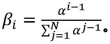 furthermore, the first radiation dose (D) 1,calculated ) May be calculated based on the first set of imaging data and by a first normalization factor k 1 Is scaled. First radiation dose (D) 1,calculated ) The spatial filtering may be performed by multiplying the first set of imaging data with a radiation excitation matrix (RFM) of the treatment plan, with a bit mask BFZ corresponding to the spatial location of the target region, and with a first normalization factor k 1 To calculate. Calculating a second normalization factor k 2 The method can comprise the following steps: by counting the dose D delivered in (N-1) passes of radiation delivery 1,calculated Summing to calculate the predicted cumulative dose (D) 1,predicted cumulative ) And calculating the planned dose (D) plan ) And a first radiation dose (D) 1,calculated ) The difference between the doses and the predicted cumulative dose (D) 1,predicted cumulative ) The ratio of (a) to (b). Second amount of radiation (D) 2,calculated ) The spatial filtering may be performed by multiplying the second set of imaging data with the RFM of the treatment plan, with a bit mask BFZ corresponding to the spatial location of the target region, and with a first normalization factor k 2 To calculate. In some variations, the first normalization factor k 1 Can be determined by the following equation:

wherein D plan Is the radiation dose or flux as specified in the treatment plan, and D 0,raw Is the radiant flux given by


D prescan Is obtained by pre-scanning an image (X) prescan ) Multiplied by the radiation excitation matrix (RFM) of the treatment plan, spatially filtered with a bit mask BFZ corresponding to the spatial position of the target region, and multiplied by the radiation flux calculated by the dose calculation matrix. Calculating the predicted cumulative dose (D) 1,predicted cumulative ) May include multiplying the first set of imaging data by a radiation excitation matrix (RFM) of the treatment plan, and adding any negative radiation fluxes that are spatially filtered with a bit mask BFZ corresponding to the spatial location of the target region.
Another variation of a radiation delivery system for delivering radiation during a treatment session may include: a gantry, a therapeutic radiation source mounted on the gantry, an imaging system mounted on the gantry, and a controller in communication with the gantry, the radiation source, and the imaging system. The controller may be configured to: acquiring imaging data of a patient positioned on a platform using an imaging system; and applying a dose of radiation to the patient with the radiation source to deliver a treatment-planned dose of radiation D plan Wherein the radiation dose is derived from the acquired imaging data. The controller may be further configured to: stopping the application of radiation to the patient; storing the amount of radiation D applied to the patient prior to stopping radiation delivery delivered,pre-interrupt And the position of the platform when the application of radiation is stopped; and resuming the application of radiation to the patient while acquiring the additional imaging data, wherein a second amount of radiation applied to the patient is derived from the additional imaging data and is according to D plan And D delivered,pre-interrupt The difference between them is adjusted.
Resuming the application of radiation may include: the patient platform is moved back to the position of the platform at the time the radiation delivery was stopped. The amount applied before radiation application is stopped is a first amount of radiation, and may be derived from imaging data x acquired during a treatment session before radiation application is stopped i And (6) obtaining. Furthermore, the first radiation dose may be determined by comparing the acquired imaging data x i Multiplication with the radiation excitation matrix RFMAnd applying a biological excitation zone mask BFZ, wherein RFM and BFZ are calculated during a treatment planning session. In some variations, applying the amount of radiation to the patient may include: in acquiring a first set of imaging data x 1 While simultaneously moving the patient table through the therapeutic radiation beam plane from the first position to the second position, a first pass of radiation is applied by moving the first set of imaging data x 1 Multiplying with a radiation excitation matrix RFM and applying a biological excitation zone mask BFZ to obtain D 1,raw And by a first normalization factor k 1 Zoom D 1,raw Deriving the amount of radiation emitted during the first pass (D) 1,calc ). Furthermore, in some variations, the first normalization factor k 1 Calculated by the following way: calculating the dose D by multiplying a pre-scan image of the patient acquired during the treatment session with the radiation excitation matrix RFM and applying the bio-excitation zone mask BFZ 0,raw (ii) a By mixing D 0,raw The cumulative predicted dose D is calculated by multiplying by the total number of radiation passes N in the treatment session 0,predicted cumulative (ii) a And get D plan And cumulative predicted dose D 0,predicted cumulative The ratio of (a) to (b). In some variations, applying the amount of radiation to the patient may further comprise: while the second set of imaging data x is being acquired 2 While simultaneously moving the patient table through the therapeutic radiation beam plane from the second position to the first position, a second pass of radiation is applied by moving a second set of imaging data x 2 Multiplying with a radiation excitation matrix RFM and applying a biological excitation zone mask BFZ to obtain D 2,raw And by a second normalization factor k 2 Zoom D 2,raw Deriving the amount of radiation (D) emitted during the second pass 2,calc ). Stopping the application of radiation to the patient may include applying the stop radiation during the second radiation pass. Additionally or alternatively, resuming the application of radiation to the patient may include: acquiring a restored set of imaging data x 2,resumed And emits an amount of radiation that passes through a set of imaging data x to be recovered 2,resumed Multiplication with a radiation excitation matrix RFM and application of a biological excitation zone maskCode BFZ to obtain D 2,raw,post-interrupt And by a second normalization factor k 2 Zoom D 2,raw,post-interrupt It can be derived that, among others, the amount of radiation that can be applied before stopping the application of radiation is D 2,raw,pre-interrupt . Additionally, resuming the application of radiation to the patient may further comprise: in acquiring a third set of imaging data x 3 While simultaneously moving the patient table through the therapeutic radiation beam plane from the first position to the second position, a third pass of radiation is applied by moving a third set of imaging data x 3 Multiplying with the radiation excitation matrix RFM, applying a biological excitation zone mask BFZ, and passing a third normalization factor k 3 Scaling, the amount of radiation emitted during the third time can be derived. In some variations, the third normalization factor k 3 Can be calculated by the following way: is calculated at D plan With the cumulative amount of radiation D applied in the first pass 1,calc And cumulative dose D applied in the second pass 2,calc The difference between them; by mixing (D) 2,raw,pre-interrupt +D 2,raw,post-interrupt ) Multiplying by N-3 to calculate the cumulative predicted dose D 2,predicted cumulative (ii) a And taking (D) plan –(D 1,calc +D 2,calc ) And cumulative predicted dose D 2,predicted cumulative The ratio of (a) to (b). In some variations, stopping the application of radiation to the patient may include stopping the application of radiation during the second radiation pass, and resuming the application of radiation to the patient may include: acquiring a second pre-scan image of the patient; moving the patient platform back to the position of the patient platform at the time the radiation delivery was stopped; and acquiring a restored set of imaging data x 2,resumed And transmitting a set of imaging data x to be restored 2,resumed Multiplying with a radiation excitation matrix RFM and applying a biological excitation zone mask BFZ to obtain D 2,raw,post-interrupt And by the recovered normalization factor k 2_resumed Zoom D 2,raw,post-interrupt Derived amount of radiation, wherein the amount of radiation applied before stopping the application of radiation is D 2,raw,pre-interrupt . Furthermore, the recovered normalization factor k 2_resumed By the following methodCalculating the formula: calculating the amount of radiation D by multiplying the second pre-scan image of the patient with the radiation excitation matrix RFM and applying the biological excitation zone mask BFZ 2,raw-interrupt (ii) a By mixing (D) 2,raw,pre-interrupt +D 2,raw,post-interrupt ) Multiplying by N-2 to calculate the cumulative predicted dose D 2,predicted cumulative (ii) a And get D plan And cumulative predicted dose D 2,predicted cumulative The ratio of (a) to (b). Resuming the administration of radiation to the patient may further comprise: in acquiring a third set of imaging data x 3 While simultaneously moving the patient table through the therapeutic radiation beam plane from the first position to the second position, a third pass of radiation is applied by moving a third set of imaging data x 3 Multiplying with the radiation excitation matrix RFM, applying a biological excitation zone mask BFZ, and passing a third normalization factor k 3 Scaling to derive the amount of radiation emitted during the third pass. Third normalization factor k 3 Can be calculated by the following way: calculating D plan With the cumulative amount of radiation D applied in the first pass 1,calc And cumulative dose D applied in the second pass 2,calc The difference between them; by mixing (D) 2,raw,pre-interrupt +D 2,raw,post-interrupt ) Multiplying by N-3 to calculate the cumulative predicted dose D 2,predicted cumulative (ii) a And taking (D) plan –(D 1,calc +D 2,calc ) And cumulative predicted dose D 2,predicted cumulative The ratio of (a) to (b).
Another variation of the radiation delivery system may include: a frame; a therapeutic radiation source mounted on the gantry and configured to apply radiation in a radiation treatment beam plane; a plurality of PET detectors mounted on the gantry; a platform movable relative to the frame; and a controller in communication with the gantry, the therapeutic radiation source, and the platform. The controller may be configured to acquire an image of the patient on the platform, calculate a normalization factor based on the image of the patient, and deliver radiation to the patient across a preselected number of shuttling passes. In each shuttle pass, the controller may be configured to: updating a radiation excitation matrix of the treatment plan using the calculated normalization factor; moving the platform from the first predetermined position to the second predetermined position and back to the first predetermined position such that the target region of the patient passes through the radiation treatment beam plane at least twice; acquiring PET data using a PET detector; delivering radiation to the patient based on the updated radiation excitation matrix and the acquired PET data; calculating a flux delivered to the patient when the platform has moved back to the first predetermined position; calculating a flux difference between a flux delivered to the patient and a treatment plan flux; and calculating an updated normalization factor based on the flux difference.
The PET detector may be coplanar with the radiation therapy beam plane, and in some variations, the acquired image may be a PET image. For example, the calculation of the normalization factor may include calculating an average of the PET intensities of the target region in the acquired PET image. The preselected number of shuttling passes may be an even number. For example, the preselected number of shuttling passes may be two or more. In some variations, calculating an updated normalization factor may include calculating a mean flux value of radiation emitted by the therapeutic radiation source. Additionally or alternatively, calculating the updated normalization factor may include calculating a ratio of an average planned dose value of radiation to an average delivered dose value of radiation for the target region. Delivering radiation based on the updated radiation excitation matrix and the acquired PET data may include: multiplying the updated radiation excitation matrix with one or more lines of response (LORs) of the acquired PET data to derive a delivery flux map, and generating radiation using the therapeutic radiation source according to the delivery flux map. In some variations, the radiation delivery system may further comprise: a movable jaw disposed above the therapeutic radiation source and a multi-leaf collimator coupled to the jaw, wherein a treatment plane is defined by a position of the movable jaw and a configuration of the multi-leaf collimator relative to the therapeutic radiation source. In these variations, the controller may be configured to move the movable jaw from the first jaw position to the second jaw position and back to the first jaw position when radiation is delivered to the patient. In some variations, the controller may be configured to calculate the predicted dose and dose value histogram by adjusting the image by the calculated normalization factor.
Another variation of the radiation delivery system may include: a frame, a therapeutic radioactive source, a radiotherapy system platform and a controller. Both the moveable jaw and the multileaf collimator may be disposed in a radiation beam path of the radiation source, and a position of the moveable jaw and a configuration of the multileaf collimator relative to the radiation source may define a treatment plane. In addition, the controller may be in communication with the gantry, the radiation source, and the radiation treatment system platform. The controller may be configured to: (a) moving a patient positioned on the platform by moving the platform from a first predetermined position to a second predetermined position such that one or more target regions in the patient pass through the treatment plane; and (b) delivering radiation to the patient with the radiation source when a portion of the one or more target areas pass through the treatment plane, wherein the delivering of radiation includes moving the movable jaw from the first jaw position to the second position and back to the first jaw position while emitting radiation from the radiation source prior to moving to the next platform position.
Moving the platform may include moving the platform in a series of predefined incremental patient platform positions, and delivering radiation to the patient may include delivering radiation at each platform position in the target region through the treatment plane. Moving the platform includes translating the platform along the longitudinal axis, and wherein moving the movable jaw includes moving the jaw such that the treatment plane is offset along the longitudinal axis. Moving the movable jaw may shift the treatment plane from about 3cm to about 6cm along the longitudinal axis and/or at a speed of about 0.5 cm/s. Further, the controller may be configured to acquire an image of the patient before radiation is delivered to the patient. For example, the system can include a plurality of PET detectors configured to acquire PET data including lines of response (LORs), wherein delivering radiation to the patient can include multiplying a radiation excitation matrix of the treatment plan with one or more LORs to derive a delivery flux map, and generating radiation using the therapeutic radiation source according to the delivery flux map. The acquired image may be a PET image. In some variations, the controller may be configured to repeat the shuttling passes of steps (a) and (b) a preselected number of times. For example, the preselected number of shuttling passes may be two or more.
Another variation of the radiation delivery system may include a gantry, a therapeutic radiation source, and a controller in communication with the gantry and the radiation source. The controller may be configured to: calculating the radiation flux delivered to the target region of the patient during a previous radiation delivery session; comparing the delivered radiation flux to the target region to the treatment plan flux to the target region and calculating a flux difference; calculating a radiation excitation matrix based on the calculated flux difference; and delivering radiation to the patient in a subsequent radiation delivery session based on the computed radiation excitation matrix and the PET data acquired during the subsequent radiation delivery session. Comparing the delivered radiation flux and the planned radiation flux may include: the average radiation flux delivered to the target region and the average treatment plan flux to the target region are compared, and a flux difference is calculated by taking the difference between the average delivered radiation flux and the average treatment plan flux. In some variations, the PET data may include line of response (LOR) data.
One variation of a method for radiation delivery may include: acquiring an image of a patient on a radiation therapy system platform, wherein the radiation therapy system further comprises a therapeutic radiation source configured to apply radiation in a treatment plane and a plurality of PET detectors; calculating a normalization factor based on the image of the patient; and deliver radiation to the patient across a preselected number of shuttling passes. Each shuttle pass may include: updating a radiation excitation matrix of the treatment plan using the calculated normalization factor; moving the patient platform from the first predetermined position to the second predetermined position such that the target region of the patient spans the treatment plane once; acquiring PET data using a PET detector; radiation is delivered to the patient based on the updated radiation excitation matrix and the acquired PET data. When the platform has moved to the second predetermined position, the radiation therapy system can calculate the flux delivered to the patient; calculating a flux difference between a flux delivered to the patient and a treatment plan flux; and calculating a flux difference between the flux delivered to the patient and the treatment plan flux. The PET detector may be coplanar with the treatment plane. Acquiring the image may include acquiring a PET image. The preselected number of shuttling passes may be an even number, such as two or more. Calculating the normalization factor may include calculating an average of the PET intensities of the target region in the acquired PET image. Calculating the updated normalization factor may include calculating a mean flux value of radiation emitted by the therapeutic radiation source. Alternatively or additionally, calculating an updated normalization factor may include calculating a ratio of an average planned dose value of radiation to a target region to an average delivered dose value of radiation. Delivering radiation based on the updated radiation excitation matrix and the acquired PET data may include multiplying the updated radiation excitation matrix with one or more lines of response (LORs) of the acquired PET data to derive a delivery flux map, and generating radiation using a therapeutic radiation source according to the delivery flux map. The radiation therapy system can further include a movable jaw disposed above the therapeutic radiation source and a multi-leaf collimator coupled to the jaw, wherein the treatment plane can be defined by a position of the movable jaw and a configuration of the multi-leaf collimator relative to the therapeutic radiation source. The method may further include moving the movable jaw from the first jaw position to the second jaw position and back to the first jaw position while delivering radiation to the patient. Some variations may further include calculating a predicted dose and dose value histogram by adjusting the image by the calculated normalization factor.
Another variation of the radiation delivery method may include: (a) moving the patient on the radiation therapy system platform from a first predetermined position to a second predetermined position in which the radiation therapy system may further include a therapeutic radiation source, both of which are disposed in a radiation beam path of the therapeutic radiation source, wherein a position of the moveable jaws and a configuration of the multileaf collimator relative to the therapeutic radiation define a treatment plane, and wherein moving the patient from the first position to the second position causes one or more target regions of the patient to span the treatment plane, and (b) delivering radiation to the patient when a portion of the one or more target regions span the treatment plane. Delivering radiation may include moving the movable jaw from the first jaw position to the second position and back to the first jaw position while emitting radiation from the therapeutic radiation source prior to moving to the next stage position. Moving the patient table may include moving the table in a series of predefined incremental patient table positions, and wherein delivering radiation to the patient includes delivering radiation at each table position of the target region through the treatment plane. Moving the platform can include translating the platform along the longitudinal axis, and wherein moving the movable jaw includes moving the jaw such that the treatment plane is offset along the longitudinal axis. Moving the movable jaw may shift the treatment plane from about 3cm to about 6cm along the longitudinal axis. The movable jaw is moved to displace the treatment plane at a speed of about 0.5 cm/s. The method may further include acquiring an image of the patient prior to delivering radiation to the patient. The radiation therapy system can further include a plurality of PET detectors configured to acquire PET data including lines of response (LORs), and wherein delivering radiation to the patient includes multiplying a radiation excitation matrix of the treatment plan with one or more LORs to derive a delivery flux map and generating radiation using the therapeutic radiation source according to the delivery flux map. The acquired image may be a PET image. The method may further comprise repeating steps (a) and (b) a preselected number of shuttling passes, wherein the preselected number of shuttling passes is two or more.
Another variation for the radiation delivery method may include calculating a radiation flux delivered to a target region of a patient during a previous radiation delivery session, comparing the delivered radiation flux to the target region to a treatment plan flux to the target region, and calculating a flux difference, calculating a radiation excitation matrix based on the calculated flux difference, and delivering radiation to the patient in a subsequent radiation delivery session based on the calculated radiation excitation matrix and PET data acquired during the subsequent radiation delivery session. Comparing the delivered radiation flux and the planned radiation flux may include comparing an average delivered radiation flux to the target region with an average treatment plan flux to the target region, and calculating a flux difference by taking a difference between the average delivered radiation flux and the average treatment plan flux. In some variations, the PET data may include line of response (LOR) data.
Drawings
Fig. 1A depicts a variation of a radiation therapy system.
Fig. 1B depicts a perspective assembly diagram of a radiation therapy system (e.g., the radiation therapy system of fig. 1A).
Fig. 1C depicts a variation of the beam shaping module.
Fig. 2A depicts a graph representing the spectrum of respiratory motion.
Fig. 2B depicts a graph representing the motion of the target area during a treatment session.
Fig. 2C depicts a planned dose distribution graph.
Figure 2D depicts a graph of the delivered dose profile.
Fig. 3A depicts a graph representing the motion of a target area during a treatment session.
Fig. 3B depicts a graph representing the motion of the target region during a treatment session in shuttle mode.
Figure 3C depicts a table showing the delivered dose to the target area after one shuttle pass and after eight shuttle passes.
Fig. 3D depicts a planned dose distribution graph.
Fig. 3E depicts a delivered dose profile plot for radiation delivered in shuttle mode.
FIG. 4 depicts a flowchart representation of a variation of a method for patient platform or couch shuttle mode.
FIG. 5 depicts a flowchart representation of a variation of a method for jaw shuttle mode.
Fig. 6 depicts a flowchart representation of a variation of a method for updating a radiation excitation matrix (RFM) during a treatment session.
Fig. 7 depicts a flowchart representation of a variation of a method for dynamically updating an RFM during an emission-guided radiation therapy session.
Fig. 8A depicts a variation of a method for radiation delivery.
Fig. 8B depicts a variation of the method in which radiation delivery is modified according to a normalization factor.
FIG. 8C depicts a variation of the pipeline normalization method.
Fig. 9A-9D depict simulated dose-volume plots or histograms (DVH) for one variation of the method based on radiation delivery in four couch shuttling passes to the planned target point region (PTV) and bio-excitation zone (BFZ) region. Fig. 9A depicts DVH curves after one shuttle pass, fig. 9B depicts DVH curves after two shuttle passes, fig. 9C depicts DVH curves after three shuttle passes, and fig. 9D depicts DVH curves after four shuttle passes.
Fig. 10 depicts a variation of a method for radiation delivery.
11A-11B are simulated DVH plots depicting the results of two radiation delivery methods for four couch shuttling passes to a planned target area (PTV) and bio-excitation zone (BFZ). Fig. 11A depicts a DVH plot when negative flux values are incorporated as part of radiation delivery.
Fig. 11B depicts a DVH plot when negative flux values are not incorporated as part of the radiation delivery.
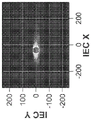
Fig. 12A-12C depict multiple views of a planned dose distribution. FIG. 12A depicts a projection of a planned dose distribution on an IEC-Z/IEC-X plane, FIG. 12B depicts a projection of a planned dose distribution on an IEC-Z/IEC-Y plane, and FIG. 12C depicts a projection of a planned dose distribution on an IEC-Y/IEC-X plane.
Fig. 13A-13C depict multiple views of a planned dose distribution. Figure 13A depicts a projection of the delivered dose distribution onto the IEC-Z/IEC-X plane, figure 13B depicts a projection of the delivered dose distribution onto the IEC-Z/IEC-Y plane, and figure 13C depicts a projection of the delivered dose distribution onto the IEC-Y/IEC-X plane.
Fig. 14A-14C depict multiple views of gamma (gamma) metric distributions. Fig. 14A depicts a projection of a gamma (gamma) metric distribution on an IEC-Z/IEC-X plane, fig. 14B depicts a projection of a gamma (gamma) metric distribution on an IEC-Z/IEC-Y plane, and fig. 14C depicts a projection of a gamma (gamma) metric distribution on an IEC-Y/IEC-X plane.
Figure 14D depicts a graph representing cumulative flux as a function of beam station for a treatment segment with four shuttle passes.
Fig. 15A depicts a variation of the radiation delivery method when there is an interruption during the shuttle pass, wherein the radiation delivery is resumed without a new pre-scan image.
Fig. 15B depicts a variation of the radiation delivery method when there is an interruption during the shuttle pass, where the radiation delivery is resumed using a new pre-scan image.
Fig. 16 is a graph depicting cumulative flux as a function of beam station for a treatment session employing four shuttle passes, with treatment interrupted at various interruption characteristics on the second shuttle pass.
Detailed Description
Radiation therapy system
A radiation therapy system that can be used with shuttle mode radiation delivery can include: a rotatable gantry that rotates about a patient treatment area, a treatment source mounted on the rotatable gantry, and a patient table that is movable within or through the patient treatment area. The rotatable gantry may be configured to rotate 0 ° to 360 ° (e.g., a continuously rotatable gantry) or only along arc segments that sweep a subset of angles (e.g., 0 ° to 180 °, 0 ° to 270 °, etc.). One example of a therapeutic radiation source is a linear accelerator (linac). One or more beam shaping elements may be disposed in a beam path of the therapeutic radiation source to define a treatment plane. For example, the beam shaping elements may include jaws and a dynamic multi-page collimator (MLC). The jaws may be positioned between the therapeutic radiation source and the MLC, or may be positioned below the MLC. Alternatively, the jaws may be split jaws, with a first portion of the jaws positioned between the therapeutic radiation source and the MLC and a second portion of the jaws positioned below the MLC and coupled to the first portion of the jaws such that the two portions move together. The jaws are movable within a beam of the therapeutic radiation source such that a treatment plane defined by the jaws may be offset in a direction parallel to the motion of the patient platform. For example, if the patient platform is moved through the patient treatment area in the IEC-Y direction, the jaws and MLCs may define a treatment plane in the IEC-XZ plane, and moving the jaws may offset the treatment plane in the IEC-Y direction. The MLC and jaws may be separated or disengaged such that offsetting or moving the jaws does not move the MLC, but in other variations, the MLC and jaws may be coupled together such that offsetting or moving the jaws also causes a corresponding offsetting or movement of the MLC. Some variations of radiation therapy systems may include a radiation detector mounted on the gantry opposite the radiation therapy source. For example, some variations may include an MV radiation detector located opposite the linac.
In addition, some radiation therapy systems may include one or more PET detectors that may be mounted on the same rotatable gantry or on a separate/second gantry that may or may not rotate around the patient treatment region. A line of response (LOR) defined by a coincident 511keV photon pair emitted by a positron annihilation event can be detected by the PET detector and transmitted to a system controller. In some variations, the patient may be injected with a PET tracer prior to the treatment session, and LORs from the PET tracer may be detected by a PET detector. For example, PET tracers may accumulate in areas of a patient with elevated metabolic rates, such as tumor areas. The system controller may be in communication with all components of the radiation therapy system and may generate commands to the therapeutic radiation source and/or gantry and/or beam shaping element and/or patient platform, for example, based on data acquired by the PET detector and/or MV detector. The system controller may also include one or more processors that may be programmed or configured to perform any of the calculations and methods described herein. The controller may also include one or more memories that may store data associated with any of the calculations and methods described herein, including but not limited to imaging data (e.g., LOR data detected by a PET detector), radiation delivery parameters and/or adjustment factors, machine commands, machine configuration, sensor data, and any other data described herein.
A variation of the radiation therapy system is depicted in fig. 1A. FIG. 1A depicts a variation of a radiation therapy system that may be used in shuttle mode radiation delivery. The radiation therapy system (100) may include: a gantry (102) rotatable about a patient treatment region (104), one or more PET detectors (106) mounted on the gantry, a therapeutic radiation source (108) mounted on the gantry, a beam shaping module (110) disposed in a beam path of the therapeutic radiation source, and a patient table (112) movable within the patient treatment region (104). The beam shaping module (110) may include movable jaws and a dynamic multi-leaf collimator (MLC). The beam shaping module may be arranged to provide a longitudinally variable collimation width of 1cm, 2cm or 3cm at the isocenter of the system (e.g. the center of the patient treatment area). The jaws may be positioned between the therapeutic radiation source and the MLC, or may be positioned below the MLC. Alternatively, the beam shaping module can include a split jaw, wherein a first portion of the jaw is located between the therapeutic radiation source and the MLC and a second portion of the jaw is located below the MLC and coupled to the first portion of the jaw such that the two portions move together. Fig. 1B is a perspective assembly view of the radiation therapy system (100). As shown, the beam shaping module may further include a primary collimator or jaw (107) disposed above the binary MLC (122). Optionally, the radiation therapy system (100) may further comprise a kV CT scanner (109) on a rotatable ring (111) attached to the rotatable gantry (102) such that the rotatable gantry (102) also rotates the ring (111). The therapeutic radiation source or linac (108) and PET detector (106) may be mounted on the same cross-section of the gantry (i.e., the PET detector is coplanar with the treatment plane defined by the linac and beam shaping module), while the kV CT scanner and ring may be mounted on a different cross-section (i.e., not coplanar with the treatment plane).
Fig. 1C is a schematic diagram of a variation of a beam shaping module comprising a splitting jaw (120) and a dynamic MLC (122). In this variation, the dynamic MLC (122) may be a binary MLC, but may be any type of MLC (e.g., a 2-D MLC). The split jaws (120) can include an upper jaw (124) positioned between a therapeutic radiation source (128) (e.g., a linear accelerator) and the MLC (122) and a lower jaw (126) positioned below the MLC (122). The upper jaw (124) and the lower jaw (126) may be coupled together by one or more plates (130) or frames. The jaws may be mounted on one or more curved linear tracks. For example, the splitting jaw (120) may be slidably mounted on one or more curved linear tracks (132). One or more plates or frames of the splitting jaw may have one or more slots sized and shaped to be larger than the cross-sectional size of the rail such that the slots may slide on the rail (as indicated by arrows (134)). Optionally, there may be additional rails orthogonal to the rails (132) to provide further support to the jaws. In this example, the tracks (132) are curved, but in other variations they may not be curved (i.e. they may be straight without any curvature). The jaws may be coupled to an actuator or motor that moves the position of the jaws along a curved linear track. Movement of the jaws along the track may result in a corresponding offset of the treatment plane along the IEC-Y axis (i.e., the axis of motion parallel to the patient platform). In other variations, the jaws may alternatively be mounted to the frame via one or more movable or rotatable attachment mechanisms (such as one or more hinges or pivots). The jaws may be capable of moving about 0.5cm to about 2cm to the right or left of an equal amount point (isocenter), with a total range of movement (end-to-end) of about 1cm to about 4 cm. This may correspond to a similar offset in the treatment plane, where the treatment plane may be offset along the longitudinal axis of the patient platform by a total range of about 1cm to about 4cm of movement. It should be appreciated that the total movement along the longitudinal axis of the patient platform (e.g., IEC-Y) may range from about 1cm to about 12cm, e.g., about 1cm, about 2cm, about 3cm, etc. In some variations, a binary MLC may include 64 leaves that define axial planes (e.g., IEC-XZ) that are each 0.6cm wide at an equivalent point, resulting in a field of view (FOV) of about 40 cm. The jaw actuator can be configured to move the jaws at a speed of about 0.25cm/s to about 2cm/s, such as about 0.5cm/s, about 1cm/s, and the like. In some variations, the jaw speed may be greater than the speed of the patient platform. Although the beam shaping module depicted and described in fig. 1A-1C includes jaws and MLCs that are immovably attached to one another (i.e., the moving or offsetting jaws do not necessarily move to offset MLCs), in other variations, the jaws and MLCs may be movably attached (i.e., the jaws and MLCs would move or offset together).
In some variations, the radiation therapy system may include a first array of PET detectors (106a) and a second array of PET detectors (106b) disposed opposite the first array, a linear accelerator (108) or a linear accelerator, and a beam shaping module (110) including jaws and a dynamic binary MLC. The system may further include a controller in communication with the gantry, the PET detector, the linac, and the MLC, wherein the controller has: one or more memories that can store treatment plans, radiation excitation matrices, flux maps, system instructions/commands; and a processor configured to perform the calculations and methods described herein. A patient located or disposed on a patient platform (112) within a patient treatment region (104) may have been injected with a positron-emitting PET tracer, and the PET tracer may accumulate at a particular region of the patient (e.g., such as a tumor region). Annihilation of a positron with a nearby electron can result in the emission of two photons traveling in opposite directions, thereby defining a LOR or positron annihilation emission path. The PET detector may detect one or more LORs. In some variations, the PET detectors may be time-of-flight PET detectors, which may help identify the location of the positron annihilation event. The previously computed treatment plan P and/or the radiation excitation matrix RFM can be updated to update the treatment plan flux map based on data acquired by the MV detector positioned opposite the therapeutic radiation source and/or LOR data acquired by the PET detector and/or PET imaging data such that the linac and MLC leaf configurations/beamlet selections account for tumor movement. The treatment plan flux map may be updated using LOR data and/or PET imaging data and/or MV detector data as the patient moves through the patient treatment region (e.g., in predefined patient table steps or increments through the patient treatment region and/or treatment plane or continuous patient table movement). Alternatively, the radiation therapy system (100) may include a CT imaging system mounted on the same gantry as the therapeutic radiation source or on a separate gantry. Additional details and examples of PET-based radiation therapy systems are described in U.S. patent application No.15/814,222, filed 2017, 11, 15, the entire contents of which are incorporated herein by reference.
The gantry (102) may be configured to rotate at a rate of from about 15RPM to about 70RPM (e.g., about 50RPM, about 60RPM), the binary dynamic MLC may be configured to change the leaf configuration within about 15ms or less (e.g., about 10ms or less, about 8ms or less), and the patient platform (112) may be configured to move at a rate of about 0.5mm/s or less. For example, a high-speed binary multi-leaf collimator may include a leaf actuation mechanism having a spring system coupled to a pneumatic system to provide sufficient power to move MLC leaves between the open and closed configurations within the time limits described above. As it rotates, the gantry (102) may move to (and/or traverse) discrete predefined circumferential firing positions. Some systems have about 100 excitation positions or angles (e.g., from about 0 degrees to about 360 degrees, with each position separated by a regular angular interval).
The treatment plan may specify the radiation dose to be delivered by the radiation therapy system to each target region of the patient. The flux and/or dose maps of the treatment plan may be used to determine jaw position/configuration, MLC position/configuration, gantry position and/or motion, and couch position and/or motion during the treatment session. In some variations, a radiation excitation matrix (RFM) may be computed as part of the treatment plan. The RFM may be a matrix that specifies the conversion from partial images (e.g., a set of LORs or incomplete image data) to radiation beamlet patterns and/or beamlet intensities to be applied to the patient during the treatment session. For example, in biologically guided radiation therapy (such as emission guided radiation therapy) in which therapeutic radiation is applied to a target region based on detected PET LORs, the RFM can be multiplied with the LOR data during the treatment session to generate a flux map that specifies the radiation dose to be delivered to each patient target region. Additional details regarding treatment planning methods and radiation excitation matrix calculations are provided in U.S. provisional patent application No.62/537,384, filed 2017, 26/7, the entire contents of which are incorporated herein by reference.
Distortion of dose adjustment
The treatment plan and/or RFM is calculated based on the images and data of the patient and/or target area prior to the treatment session (typically weeks or days prior to the treatment session). It is not uncommon for a target region, particularly in or near the lung (e.g., a lung tumor), to move during a treatment session and deviate from its position, particularly during treatment planning. The irregular and/or unpredictable movement of the target region, coupled with the movement of the jaws and/or MLC and/or couch, can adjust the delivered dose such that the radiation provided to non-target tissue and/or certain areas of the target region is over-or under-irradiated (e.g., hot and cold spots, respectively). As the patient table or couch is advanced in the longitudinal direction (IEC-Y) in the treatment region, the target volume is irradiated with a fan-shaped beam of radiation (e.g., a treatment plane) defined by the beam shaping elements of the system. Radiation treatment systems with fast rotating gantries (e.g., greater than about 15RPM, e.g., about 60RPM or about 70RPM) and fast binary MLC (e.g., leaf transition time from about 8ms to about 15ms) can result in a pitch (pitch) (i.e., the ratio of couch movement in one rotation to the thickness of the collimator along IEC-Y) of less than about 0.3. It has been suggested that movement of the patient and couch in the IEC-Y (longitudinal direction) may be a significant contributor to dose modulation distortion.
One example of dose modulation due to tumor motion is depicted in fig. 2A-2D. Fig. 2A and 2B are graphs showing tumor motion (due to respiratory motion) on a radiation therapy system having a patient table or couch moving at a speed of about 0.5mm/s or less, and a binary MLC leaf size of 20mm in the longitudinal direction (e.g., IEC-Y), where the time to traverse the beam in the longitudinal direction would be about 40 seconds (20mm/[0.5mm/s ]). The time to transect the beam may be referred to as the "jaw dwell time". Whereas in the transverse plane (e.g., in the IEC-XZ plane), in a system with 100 firing positions, the time scale (e.g., leaf transition speed) for a binary MLC is on the order of more than about 0.01 seconds. In this radiation therapy system, the rate of opening and closing of the binary MLC leaves is relatively fast compared to the couch motion speed. As shown in fig. 2A, the main components of the respiratory motion have a frequency of about 0.2 Hz. Dose adjustments caused by respiratory motion and patient table motion can be interpreted as a function of jaw dwell time changes. The dose D received at any given point (y) along the longitudinal axis (IEC axis) in the jaw reference frame can be expressed as follows:
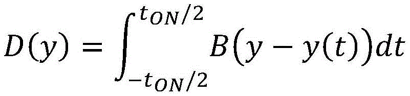
where Y is the beam center or position of the machine in the longitudinal direction (IEC-Y) and B defines the beam profile for a given system. y (t) is the tumor motion profile as seen in the jaw reference frame and can be described as:
y(t)=v couch t+y breathing (t)
the integral over time represents an average of the motion over a period of time as described in the paragraph above and also represented in fig. 2B. Due to respiratory motion, the target region (e.g., a lung tumor) may shift forward and backward, moving in and out of the jaw window (200), resulting in irregular dose delivery to the target region. The dose at a given point y may be directly proportional to the residence time of the tumor inside the jaw window (200). Variations in residence time lead to irregular dose modulation and dose distribution. Fig. 2C depicts the planned dose distribution (e.g., IMRT planned dose profile) of the Clinical Target Volume (CTV) and the Planned Target Volume (PTV) plotted with solid black lines. The ideal radiation delivery is to deliver a sufficient amount of radiation with a uniform dose distribution within the boundaries of the target region. However, as the target area moves with the radiation being delivered (e.g., due to patient breathing, patient table movement through the treatment plane, and/or rotation of the therapeutic radiation source around the patient), the delivered dose may deviate from the planned distribution. Fig. 2D depicts a simulated dose distribution resulting from radiation delivery to the target region as the target region moves in a manner similar to the respiratory motion described and depicted in fig. 2A and 2B. As shown, there are areas of over-illumination ("hot spots") (202) and under-illumination ("cold spots") (204).
Shuttle mode
A method that may help address dose adjustments due to patient or target region motion may include introducing predetermined and known motion into a radiation therapy system having frequency components that are not related to respiratory motion (e.g., having frequency components outside a frequency band around about 2 Hz). One variation of the method may include moving the patient table (or couch) and/or the beam shaping elements (such as jaws) in a repetitive or periodic manner such that the target region of the patient makes multiple passes through the treatment plane during the treatment session. For example, during a treatment session, the patient platform may be moved from the first predetermined position to the second predetermined position and back to the first predetermined position such that the target region spans the treatment plane at least twice. Such repetitive couch motions may be referred to as couch shuttling, where one couch shuttling cycle or pass includes moving from a first position to a second position while delivering radiation from a therapeutic radiation source. The continuous shuttling may include moving the couch from the second position back to the first position while delivering radiation from the therapeutic radiation source. The couch may be moved continuously as radiation is delivered, or may be stepped along the longitudinal axis (along IEC-Y) to a series of couch positions so that radiation is delivered only when the couch is stopped at these predetermined positions (or beam stations). Alternatively or additionally, during the treatment session, the jaws may be moved from the first predetermined jaw position to the second predetermined jaw position (i.e., in a first jaw shuttle pass) and back to the first predetermined jaw position (i.e., in a second jaw shuttle pass) such that a treatment plane at least partially defined by the jaws sweeps across the target area at least twice in two jaw passes. Such repeated jaw movement may be referred to as jaw shuttling, where one jaw shuttling cycle or pass includes moving from a first jaw position to a second jaw position while delivering radiation from a therapeutic radiation source. Sequential jaw shuttling may include moving the jaws from the second jaw position back to the first jaw position while delivering radiation from the therapeutic radiation source. The opening or aperture of the jaws may remain constant as the jaws shuttle. In other variations, the opening or aperture of the jaws may be changed while the jaws are shuttling. Adjusting the speed of couch and/or jaw movement during the couch and/or jaw shuttle mode may help address dose adjustment distortion caused by respiratory motion by sweeping the treatment plane over the target region at a frequency unrelated to the frequency peaks of respiratory motion. For example, shuttling the couch and/or jaws over a time scale of about 70 seconds may help mitigate distortion due to respiratory motion having frequency peaks or components over a time scale of about 5 seconds (e.g., about 0.2 Hz). Fig. 3A and 3B are graphs showing movement of the target area over a 300 second treatment interval or segment, with one couch or jaw shuttle pass in fig. 3A, and eight couch shuttle passes in fig. 3B. In shuttle mode, the couch or jaws are returned to the home position about every 70 seconds (although couch or jaw speed may be adjusted such that the couch completes a shuttle trajectory (i.e., a pair of passes) about every 80 seconds, about every 90 seconds, about every 100 seconds, etc. as shown in the table of FIG. 3C, a treatment session including multiple shuttle cycles (e.g., 8 shuttle passes) produces a dose distribution closer to the planned dose than a treatment session having a single shuttle cycle (e.g., 1 shuttle pass). the resulting dose distribution is shown in FIG. 3E (while the planned dose distribution is reproduced in FIG. 3D). CTV and PTV (together, which may include a target region or a radiation excitation region) are drawn with solid black lines.
While the couch shuttle mode and the jaw shuttle mode may be described separately, it should be understood that both the couch and the jaws may be shuttled simultaneously and/or sequentially during a treatment session (e.g., on a first pass in the jaw shuttle mode, a second pass in the couch shuttle mode, etc.). Combinations of motion between the couch and the jaws may be used to achieve the motion profile of fig. 3B. This combined couch and jaw shuttle may be beneficial because it may be used to significantly reduce patient acceleration, particularly with increased shuttle passage. For example, in the "peak" in fig. 3B (where the shuttle changes direction), the shuttle effect can be achieved by jaw shuttling (so that most of the acceleration is at the jaws, while the acceleration at the couch is almost zero). The methods may be used with a radiation therapy system configured for continuous couch motion and/or step-and-shoot couch motion.
Shuttle of deck chair
The flow chart in fig. 4 represents a variant of the method for shuttling a couch. The method (400) may optionally include loading (402) a patient on a radiation therapy system platform and acquiring (404) an image of the patient. The acquired images may be used to register the patient's position and orientation with the coordinate system of the radiation therapy system and/or to normalize the treatment plan prior to beam turn-on. The method (400) may include moving (406) the patient table from a first predetermined table position to a second predetermined table position such that all target areas in the patient span the treatment plane and are irradiated by the therapeutic radiation source. In some variations, the therapeutic radiation source, the beam shaping module (e.g., jaws and dynamic binary MLC), and the gantry can apply flux to the patient based on the detected LOR data convolved or multiplied by the treatment plan RFM. Optionally, the method (400) may include updating (407) radiation delivery parameters based on the acquired PET data and/or MV detector data. For example, updating radiation delivery parameters may include normalizing the radiation flux derived by multiplying acquired PET data with the RFM, recalculating the RFM based on the delivered dose or flux calculations, and/or updating jaw, MLC, couch, and/or gantry instructions, and/or using one or more scaling factors (such as one or more normalization factors, one or more damping factors, etc.) to adjust or modify the radiation flux for delivery. The emitted flux and/or delivered dose (e.g., single shuttle pass and/or cumulative) may optionally be calculated. The method (400) may include moving (408) the patient platform from the second predetermined platform position to the first predetermined platform position while providing therapeutic radiation in the treatment plane as the target region spans the treatment plane. The method (400) may include repeating (410) steps (406) and (408) any number of times (e.g., one or more), with or without optional step (407). In some variations, steps (406) and (408) may be repeated an even number of shuttle cycles or times (e.g., 2, 4, 6, 8, 10 times) during the treatment session.
Shuttling of jaws
A variation of the method for jaw shuttling is represented by the flow chart in fig. 5. The method (500) may optionally include loading (502) a patient on a radiation therapy system platform and acquiring (504) an image of the patient. The acquired images may be used to register the patient's position and orientation with the coordinate system of the radiation therapy system and/or to normalize the treatment plan prior to beam turn-on. The method (500) may include moving (506) the patient platform from a first predefined platform position to a second predefined platform position while moving the jaws from the first predefined jaw position to the second predefined jaw position and back to the first predefined jaw position n times such that all target areas in the patient span the treatment plane and are irradiated by the therapeutic radiation source. n can be any number (e.g., 1, 2, 3, 4, 5, 7, 9, 11, etc.), and in some variations n can be an even number, e.g., 2, 4, 6, 8, 10, etc., and the rate or speed of jaw movement can be from about 0.25cm/s to about 2cm/s, e.g., about 0.5cm/s, about 1 cm/s. In some variations, the therapeutic radiation source, the beam shaping module (e.g., jaws and dynamic binary MLC), and the gantry can apply flux to the patient based on the detected LOR data convolved or multiplied by the treatment plan RFM. While the jaws are shuttling between the first and second predetermined jaw positions, the configuration of the MLC may change (i.e., the leaves may transition between the open and closed states) according to a flux map resulting from multiplying or convolving the RFM with the LOR data (e.g., based on instructions to segment the flux map). Optionally, the method (500) may include updating (507) radiation delivery parameters based on the acquired PET data and/or MV detector data. For example, updating radiation delivery parameters may include normalizing the RFM, recalculating the RFM based on the delivered dose or flux calculations, and/or updating jaw, MLC, couch, and/or gantry instructions, and/or adjusting or modifying the radiation flux using one or more scaling factors (such as one or more normalization factors, one or more damping factors, etc.) for delivery. The emitted flux and/or delivered dose (e.g., single shuttle pass and/or cumulative) may optionally be calculated. The method (500) may include moving (508) the patient platform from the second predefined platform position to the first predefined platform position while moving the jaws from the first predefined jaw position to the second predefined jaw position and back to the first predefined jaw position n' times such that all target areas of the patient span the treatment plane and are irradiated by the therapeutic radiation source. n ' may be any number (e.g., n ' ═ 1, 2, 3, 4, 5, 7, 9, 11, etc.), and in some variations, n ' may be an even number, e.g., 2, 4, 6, 8, 10, etc., and may or may not be the same as n. The method (500) may optionally include repeating (510) steps (506) and (508) (with or without optional step (507)) an even number of shuttle cycles or times (e.g., 2, 4, 6, 8, 10) during the treatment session. An optional step (510) is included to combine both recliner and jaw shuttling. As previously mentioned, the jaws may be moved at a rate of about 0.25cm/s to about 2cm/s (e.g., about 0.5cm/s, about 1cm/s), and the distance between the first and second predetermined jaw positions may be from about 1cm to about 4cm, e.g., about 1cm, about 2 cm. The frequency of jaw shuttling may be about 4 to about 5 times the primary frequency component of respiratory motion.
Transport and interaction distortion mitigation
As briefly described above, the radiation delivery parameters may optionally be updated during the treatment session. Updating the delivery parameters may help to mitigate dose adjustment distortions due to patient motion. In some variations, the method may include calculating a flux delivered to the patient during a shuttle pass (couch and/or jaw shuttle pass), comparing the delivered flux to the treatment plan flux, and calculating a flux difference, and updating the RFM of the treatment plan to deliver the flux difference in a subsequent shuttle pass. The flux calculation may be an average flux over one or more target regions. The flux difference may be calculated/estimated in a static patient reference frame and delivered in one or more subsequent passes without any further imaging data (e.g., without any PET imaging data, CT imaging data, or MV detector data). Alternatively, the flux difference can be measured in a tumor-point of view (POV) reference frame. In some variations, the method may include calculating a cumulative delivered flux across all previous shuttling passes in the treatment session (not just the flux delivered in a single shuttling pass). Alternatively or additionally, a method may include calculating a dose delivered to the patient during a shuttle pass (couch and/or jaw shuttle pass), comparing the delivered dose to a treatment plan dose and calculating a dose difference, and updating the RFM of the treatment plan to deliver the dose difference on a subsequent shuttle pass. The dose calculation may be an average dose over one or more target regions. These methods may also help compensate or correct for dose adjustment distortions due to limitations/constraints of the radiation therapy system. System limitations/constraints may include noise due to dynamic binary MLC configurations or radiation beam shapes that do not exactly match the filtered partial images (e.g., flux maps based on LOR data multiplied by RFM), noise in the imaging system (e.g., PET, CT, MRI imaging systems), etc. Updating the RFM and/or delivery parameters (e.g., delivery flux map, segmented machine instructions, etc.) during a treatment session based on real-time delivery values/metrics (e.g., flux, dose, imaging data such as PET LOR) may facilitate continuous distortion correction during the session. Periodic updates to the RFM and/or delivery parameters can help adjust each successive radiation delivery segment (or shuttling pass) so that the cumulative delivered flux or dose converges to the planned/prescribed flux or dose delivery profile.
Fig. 6 depicts a flowchart representation of one method for updating the RFM during a treatment session. The method (600) may include calculating (602) a flux delivered to the target region after the first shuttle pass. The shuttling may be jaw shuttling and/or recliner shuttling. The delivered flux may be calculated based on therapeutic radiation source dose chamber measurements and/or radiation beam pulse parameters (e.g., frequency, duration, duty cycle, number of pulses, etc.) and/or MLC leaf configurations and/or jaw configurations. Alternatively, the delivered flux can be calculated using MV detector data. The method (600) may include comparing (604) a delivered flux to the target region (e.g., an average delivered flux over the target region) with a treatment plan flux to the target region (e.g., an average plan flux over the target region) (604) and calculating a flux difference Δ f (e.g., an average flux difference over the target region), and calculating (606) a new or updated radiation excitation matrix (RFM) based on the flux difference Δ f. After updating the RFM, the radiation therapy system can deliver (608) the flux difference Δ f to the target region during a subsequent shuttling pass using the updated RFM. For example, in biologically guided radiation therapy, the treatment volume can be adjusted by multiplying the imaging data (e.g., partial images) acquired during the treatment session by the volume of the volumeThe new RFM delivers the flux difference Δ f. In emission-guided radiation therapy (a type of biologically-guided radiation therapy), the updated RFM can be multiplied by one or more of the detected LORs to generate a delivered flux map. The delivery flux map may then be divided into machine instructions (e.g., MLC, linear accelerator, gantry, patient table/couch, and/or jaw instructions) that emit radiation to the patient according to the flux map. The method (600) may also be used to update the RFM over multiple target areas. For example, the flux delivered to the plurality of target regions (e.g., average flux) can be calculated to calculate the difference for each target region (Δ f for i target regions) as compared to the planned flux (e.g., average planned flux) for each of the plurality of target regions TRi ) And the flux differences across all target areas can be averaged together (or otherwise normalized) to update the RFM. In some variations, the RFM may be updated or optimized such that the flux or dose delivery metric is satisfied for a maximum number of target regions. The method (600) may also be performed using dose calculations instead of flux calculations. In emission guided radiation therapy, the method (600) may be performed using PET or LOR data (e.g., average PET intensity over the target region).
Pipeline normalization
In typical radiation delivery, corrections or adjustments to the treatment plan and/or radiation delivery parameters are applied once before treatment begins. That is, the correction or adjustment based on the acquired treatment session pre-scan image is calculated once and referenced once to the treatment plan and/or radiation delivery parameters before the beam is turned on. However, since the update only occurs once at the beginning of a treatment session, any dose adjustment distortion may not be corrected. Using the couch and/or jaw shuttle mode described herein, corrections or adjustments to treatment plans and/or radiation delivery parameters may be calculated and applied between shuttle passes. In each pass, the acquired data (e.g., PET imaging data or LOR, MV detector data, etc.) from the previous pass can be used to estimate the amount of flux or dose that has been delivered to the target region. That is, the previous imaging data may be used to predict the future dose in the next pass. For example, by adjusting the RFM, and/or scaling or offsetting the transmit flux of the current shuttle pass with a normalization factor that can be dynamically updated based on the flux and/or dose delivered in the previous shuttle pass, the next shuttle pass can be corrected by the radiation flux or dose delivered up to that point in the treatment session. This dynamic or pipeline normalization can help correct for errors in image noise or changes detected during transport, including changes in attenuation distortion from moving structures that may be outside the target region. In some variations where multiple tumor regions are to be irradiated, a normalization factor may be calculated for each region, where each region-specific normalization factor may bind factors and changes specific to that particular tumor region. Each normalization factor for each region may be calculated using any of the methods described herein. Alternatively, there may be a single global normalization factor for all tumor regions.
An illustrative method for dynamically updating an RFM during an emission-guided radiation therapy session is depicted in fig. 7. Although these methods (and others included herein) are described in the context of delivering radiation based on PET image (e.g., LOR) data, it should be understood that these methods may be used with any biologically guided radiation therapy imaging modality, including but not limited to radiation delivery based on CT partial image data, radiation delivery based on MRI partial image data. The method (700) may optionally include loading (702) a patient on a radiation therapy system patient table or couch and acquiring (704) images of the patient, including one or more target regions in the patient. In emission guided radiotherapy, a PET tracer (e.g., one that accumulates at a tumor region) can be introduced into a patient, and the pre-scan can be a PET image.
The method (700) may include calculating (706) a Normalization Factor (NF) based on the pre-scan image and the image used to generate the treatment plan. The NF can be calculated by calculating the average PET imaging signal of the pre-scan within the target region (i.e., treatment field or radiation excitation region) and calculating the average PET signal of the treatment plan image within the same target region (i.e., treatment field or radiation excitation region). The NF may be the ratio of the average planned PET imaging signal and the average pre-scan PET imaging signal.
Alternatively, in some variations, the PET pre-scan image may be used to predict the dose or flux that will be delivered in a shuttling pass immediately following the pre-scan. For example, the pre-scan image may be used to predict or estimate the real-time flux or dose delivered that will meet certain delivery metrics. The pre-scan image may be normalized by NF. The pre-scan image can now be used to estimate the dose delivered by the radiation and may be significantly insensitive to image noise of the PET image. The normalization factor may also be used to normalize the average treatment plan flux or average treatment plan radiation dose of the target region.
The method (700) may include adjusting (708) the treatment plan RFM based on the calculated NF. Adjusting the RFM by the NF may include modifying the RFM using any linear operation or transformation based on the NF. Examples of linear operations may include multiplying, convolving, and/or scaling the RFM by NF. In some variations, it may also include adding or subtracting constants to the RFM based on NF. The method (700) may then include moving (710) the patient platform from the first predetermined platform position to the second predetermined platform position (i.e., the first couch shuttle pass) and back to the first predetermined platform position (i.e., the second couch shuttle pass) such that all target regions in the patient intersect the treatment plane at least once (e.g., one or more times, two or more times, etc.). While moving the patient table, the target area may be illuminated based on the adjusted RFM and PET LOR data acquired by the PET detector. When the patient platform has returned to the first predetermined platform location, the NF may be updated based on the flux and/or dose delivered during the shuttling pass (712). In some variations, the NF may be updated based on PET LOR data acquired during the shuttle pass. For example, the updated NF may be calculated by taking the ratio of the planned flux (e.g., average planned flux) to the target region (e.g., treatment field, radiation excitation region) to the actual delivered flux (e.g., average delivered flux) to the target region. Alternatively or additionally, the updated NF may be calculated by taking the ratio of the planned dose (e.g., average planned dose) to the target region (e.g., treatment field, radiation excitation region) to the actual delivered dose (e.g., average delivered dose) to the target region, where the delivered dose is calculated based on the delivered flux and the pre-scan image or treatment plan image. Updating the NF based on the flux calculation may help the radiation delivery meet flux-based metrics, such as overall savings for the monitoring unit, while updating the NF based on the dose calculation may help the radiation delivery meet dose-based metrics (e.g., D95 coverage, maximum OAR dose). In emission guided radiation therapy, the NF may be updated based on the PET intensity on the target region (e.g., based on a ratio of the average PET intensity of the target region of the PET planning or pre-scan image to the average PET intensity of the target region based on LOR data acquired during the treatment session). As described above, the RFM may be updated using any linear operation or transformation based on NF. Optionally, the method (700) may include repeating (714) steps (710), (712) any number of times during the treatment session, and in some variations, an even number of times during the treatment session, and may stop when the delivered flux or dose converges to the planned flux or dose.
While method (700) provides an example of dynamic normalization using patient platform or couch shuttling, it should be understood that method (700) may also be used in jaw shuttle mode, where NF and RFM are updated after each jaw shuttle pass. In jaw shuttle mode, it may be that the patient platform completes only one pass during the treatment session because the jaws have completed multiple shuttle passes over a single platform shuttle pass. Alternatively or additionally, the method (700) may be used in a combined recliner and jaw shuttle mode.
In some variations, a method for radiation delivery may include using one or more adjustment factors (such as one or more of a normalization factor, a damping factor, a weighting factor, etc.) to adjust a radiation flux or dose to be emitted or delivered. The radiation flux or dose to be fired or delivered during a particular shuttle pass (e.g., couch/platform shuttle and/or jaw shuttle) may be scaled and/or offset by an adjustment factor. In some variations, the adjustment factor may be adjusted and/or updated for each shuttle pass such that the adjustment factor may reflect the latest state of the patient (e.g., using imaging data, and/or images and/or other physiological data) and the radiation delivered during the treatment session. For example, the adjustment factor may be updated or adjusted based on the radiation flux or delivered dose emitted during the previous shuttling pass and the amount of flux or dose as prescribed by the treatment plan. In one variation, the flux (or dose) to be delivered in the shuttling pass may be scaled by a normalization factor (and/or optionally a damping factor), which may be calculated based at least in part on the radiation delivered in the previous shuttling pass and the imaging data acquired during the previous shuttling pass (and/or any other imaging data acquired during the treatment session). By scaling the radiation flux or dose by the adjusted normalization factor for each shuttle, convergence of the cumulative radiation delivered towards the planned radiation flux or dose (i.e., the radiation flux or dose specified by the treatment plan) may be facilitated. In the case of emission-guided radiation therapy in which the radiation flux or dose applied to the patient is calculated based on imaging data acquired during the treatment session (e.g., PET imaging data), scaling or otherwise adjusting the radiation flux or dose with a normalization factor that accounts for the cumulative flux or dose already delivered during the session and the difference between the delivered and planned radiation doses (e.g., as specified by the treatment plan and/or clinician) may help compensate for any radiation delivery errors, fluctuations, and/or unexpected or unintentional changes due to tumor motion, patient motion, and/or variable tracer uptake, etc. Although the methods included herein are described in the context of emission-guided or bio-guided radiation therapy using PET tracers and positron emission data, it should be understood that the methods may also be used in any radiation therapy modality that applies radiation using data acquired in real time during a therapy session. In addition, the methods described herein for calculating one or more normalization factors may use radiation flux, which may alternatively or additionally use radiation dose to calculate the normalization factor. The radiation dose value or profile can be derived from the flux value or profile using a dose calculation matrix a, which can be a linear operator that maps flux to dose in image space. Specific reference to a radiation flux or dose in any of the methods described herein may more generally refer to the amount of radiation emitted or delivered to a target region.
Optionally, for any of the methods described herein, the treatment time and/or couch shuttle pass number N may be selected prior to radiation delivery (although these methods may also be applicable to jaw shuttling). The treatment time and/or the number of shuttling passes N may be determined or selected, for example, during treatment planning, before a treatment session is set for the patient, or after a treatment is set for the patient but before the treatment beam is activated. Alternatively, the damping factor α (from which the normalized damping factor β can be derived) can be selected according to the desired radiation delivery rate across multiple shuttling passes. Given the shuttle pass number N and the damping factor α, the normalized damping factor β can be derived as follows:

for example, in some variations, the damping factor α may be selected such that a greater proportion of the prescribed or planned radiation flux or dose is delivered in an earlier shuttle pass than in a later shuttle pass (i.e., the radiation flux emitted in the first pass is greater than the radiation flux emitted in the last pass). In this manner, the earlier shuttling is used to deliver most of the planned radiation dose, while the later shuttling is used to deliver flux corrections or adjustments that compensate for any errors, distortions, and/or motions that may occur during the treatment session (e.g., distortions of interactions, patient or tumor motion). In any of the methods included herein, the damping factor α can be from 0 to about 1, e.g., about 0.5, 0.6, 0.7, 0.75, 0.77, 0.8, 0.83, 0.85, 0.90, 0.91, 0.97, 1, etc. In addition to specifying the number of shuttling passes, N, the duration of the treatment session may also be specified. In some variations, the treatment session is ongoingThe time taken for each shuttle pass may be kept constant and may be adjusted according to the number of shuttle passes. That is, as the number of shuttling passes increases, the time per shuttling pass may be reduced, and the dwell time of the target area in the plane of the therapeutic radiation beam for a particular shuttling pass may be reduced. The cumulative residence time across the entire treatment session (e.g., across all N shuttle passes) may remain approximately constant regardless of the number of shuttle passes, as residence time is reduced accordingly. In the example described herein, the number of shuttle passes, N, may be four and the damping factor, α, may be 0.83 (i.e., 1/1.2), but N and α (and subsequently β) may vary as desired. For example, in a therapy session where N is 4 and α is (1/1.2) or 0.8333, the normalized damping factor for each of the four passes may be β 1 =0.33,β 2 =0.28,β 3 =0.23,β 4 0.19. While the normalization factor and one or more damping factors (α, β) may be used to adjust the radiation flux delivered to the target region during the shuttling pass, the radiation flux may be adjusted using only the normalization factor, multiple normalization factors, a single damping factor, and/or any other additional factors that adjust the delivered radiation during the treatment session to reflect the patient and/or system condition.
Fig. 8A depicts a variation of a method of modulating radiation applied during treatment for each shuttling pass. As previously described, shuttling may include moving the patient table or couch from the first position to the second position such that one or more tumor regions in the patient traverse the therapeutic radiation beam plane once. The couch may be moved continuously with radiation delivery (e.g., helical radiation delivery), or may be moved in steps such that radiation is delivered only when the couch is stopped at a predetermined couch position or step (e.g., beam station delivery, therapeutic radiation beam stopped while the couch is moving, and turned on when the couch is stopped). Although the method described below is performed in the context of shuttling a couch, it should be understood that a similar method may be applied to jaw shuttling. The method (800) may include moving (802) a patient from a first position (i.e.,by moving the patient table) to a second position such that the patient traverses the radiation treatment plane while acquiring imaging data and a first amount of radiation is applied (804) as the patient traverses the radiation beam plane. This may be referred to as a first shuttle pass, and may be based at least in part on imaging data (e.g., a full image, such as a pre-scan image X of the patient taken at the beginning of a treatment session) acquired during the first pass of the treatment plan prescan And/or a portion of an image, such as one or more LORs or positron annihilation emission paths) and one or more adjustment factors (e.g., a first normalization factor and/or a first damping factor). The method (800) may then include moving (806) the patient from the second position (i.e., by moving the patient table) to the first position such that the patient traverses the radiation treatment plane while acquiring imaging data, and applying (808) a second amount of radiation as the patient traverses the radiation beam plane, wherein the second amount of radiation is different from the first amount of radiation. This may be referred to as a second shuttle pass, and may be based at least in part on the treatment plan, imaging data acquired during the second pass (e.g., a full image, such as a pre-scan image X of the patient acquired at the beginning of the treatment session) prescan And/or a portion of an image, such as one or more LORs or positron annihilation emission paths) and one or more adjustment factors (e.g., a second normalization factor and/or a second damping factor) and the amount of radiation delivered in the previous (first) pass. The second normalization factor and/or the second damping factor may be different from the first normalization factor and/or the first damping factor. Steps (802- > 804) and/or (806- > 808) may be repeated as many times as needed or as specified (e.g., up to N shuttle passes). The number of shuttling passes, N, may be odd or even, and therapeutic radiation may be applied as the patient is alternately shuttled between the first and second positions. In some variations, the distance between the first and second locations may span a substantial length of the patient's body, and may be, for example, at least as long as the distance between the target regions that are furthest from each other (i.e., along the longitudinal IEC-Y axis), or at least as long as the largest dimension of a single target region (i.e., along the longitudinal IEC-Y axis)The length of the target area of the IEC-Y axis).
In some variations in which the radiation delivered to the target region may be determined, at least in part, by imaging data (and/or any patient or system data) acquired during the treatment session, the flux emitted by the radiation therapy system may be adjusted to help ensure that the delivered dose cumulatively converges to the prescribed dose (i.e., treatment plan or D) plan The indicated dose). Adjustment factors for a particular shuttle pass may be derived based on the acquired imaging data (and/or patient or system data), the amount of radiation that has been delivered, the treatment plan parameters, and/or any other filter or scaling or weighting factor, and the adjustment factors may be calculated and/or updated for each shuttle pass.
Fig. 8B depicts a variation of a method in which the radiation applied during a shuttle pass is modified or adjusted according to a normalization factor calculated prior to the start of the shuttle pass, and the normalization factor is updated for each shuttle pass (i.e., pipeline normalization). The method (820) may include calculating (822) a normalization factor k i Applying (824) an i-th pass of radiation while acquiring imaging data, wherein based on the acquired imaging data and the calculated normalization factor k i To calculate the emitted radiation flux, a normalization factor k is calculated (826) i+1 Applying (828) an ith pass of radiation while acquiring imaging data, wherein based on the acquired imaging data and the calculated normalization factor k i+1 The emitted radiation flux is calculated and the calculation of the normalization factor and the application of radiation (826-828) are repeated (830) for N radiation delivery passes, i-1, …. In a variant, the normalization factor k i+1 Can be calculated by: taking the cumulative planned radiation flux or dose D plan The difference from the radiation flux that has been delivered so far (i.e. in all previous shuttle passes); and if each of the future shuttle passes delivers the same amount of radiation as delivered in the previous shuttle pass, normalizing (e.g., dividing) the difference between the planned flux and the delivered flux by the predicted amount of radiation to be applied to the target areaMay not be divided into discrete flux values or levels. The radiation that is cumulatively emitted during a previous shuttle pass may be calculated based on commands and configurations of the radiation therapy system (e.g., pulse parameters from the therapeutic radiation source, MLC configuration, gantry rotation, etc.) and/or sensor data (e.g., MV detector data, dose room data, position sensor data from the MLC, couch, gantry, etc.) and/or imaging data (e.g., PET data, CT data, MRI data, etc.). In emission-guided radiation therapy (e.g., bio-guided radiation therapy) in which the imaging data includes positron annihilation emission data (i.e., LOR data), the acquired PET emission data (x) may be combined by combining the acquired PET emission data (x) i ) Multiplication with RFM from the treatment planning system, masking with a spatial filter (BFZ) that limits radiation delivery to the target region (i.e., the biological excitation zone), and optionally employing one or more normalizations (k) i ) And/or damping factor (. beta.) i ) Scaling is performed to calculate the radiation emitted by the radiation therapy system. Acquired PET emission data (x) i ) One or more LORs may be included, but a sufficient number of LORs to generate a complete or full PET image may not be included. For other radiation therapy systems, the imaging data may include two-dimensional projection X-ray images (for a CT imaging system) or MRI sub-sampling in k-space (for an MRI imaging system). Can be based on a pre-scan image (X) of the patient taken at the beginning of the treatment session prescan ) To calculate the first shuttle pass (k) 1 ) The normalization factor of (1).
In one variation, the normalization factor for the shuttle pass index i (where i ═ 1, 2, …, N shuttle passes) may be calculated as follows:
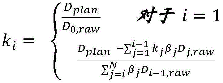
Wherein D plan Is the radiation dose or flux, beta, specified in the treatment plan i Is a damping factor, and D i,raw Is delivered (or to be delivered) for shuttle pass i according to a treatment plan without any real-time treatment session data basedA modulated radiant flux. D i,raw May be a calculated radiation flux (e.g., having a continuous flux value) or a segmented radiation flux (e.g., having discrete flux values or levels), where the segmented radiation flux may include flux values representing flux values deliverable by the radiation therapy system. In some variations, for radiation delivery based on imaging data acquired during a treatment session,
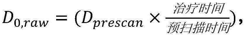

Where A is a dose calculation matrix generated based on radiation treatment system parameters that map flux to dose in image space, X prescan Is an image acquired at the beginning of a treatment session prior to delivery of any therapeutic radiation (e.g., a complete image, such as a complete PET image, a complete CT image, and/or a complete MRI image), RFM is a radiation excitation matrix generated by the treatment planning system to specify the conversion of image data (e.g., a partial image, such as a set of LOR or 2-D X ray projections or MRI subsampling in k-space, or incomplete image data) into a radiation beamlet pattern and/or beamlet intensities, and BFZ is a spatial filter comprising a bitmap that specifies target regions while masking non-target regions. "treatment time" is the total treatment delivery time defined by the treatment planning system that can be selected or determined by the clinician or user, and "pre-scan time" is the acquisition of the pre-scan image X prescan The total time spent.
Item(s)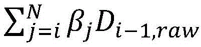 May indicate that the same amount of radiation will be delivered to the target area if each of the future shuttle passes delivers the same amount of radiation as that delivered in the previous shuttle pass and may also be referred to asIs D i,predicted cumulative The predicted cumulative flux (which may not be divided into flux levels or values deliverable by the radiation therapy system). In some variations, D i,predicted cumulative Can be expressed as:
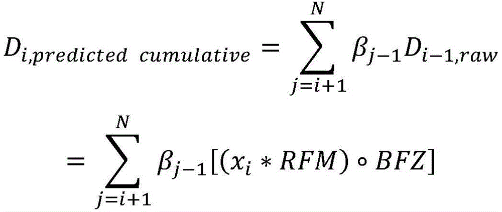
for shuttle passes after the first shuttle pass (2)<=i<N), normalization factor k i It can also be written as follows:
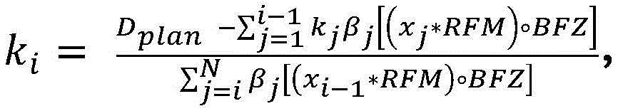
Wherein x is i Representing imaging data acquired during the shuttle pass i. In method (820), steps (822) and (826) may calculate the normalization factor k as described above i And k i+1 。
Radiation flux delivered by the ith shuttle (D) i,calc ) The following can be calculated:
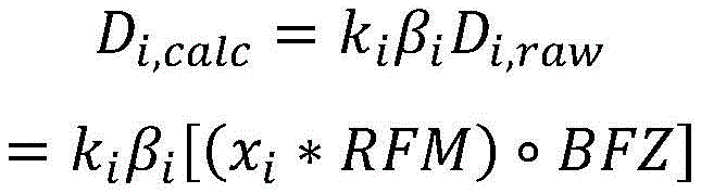
when applied to method (820), the emitted radiation flux in (824) may be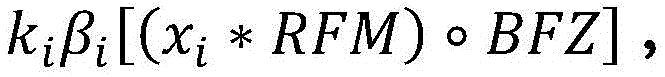 And the radiation flux emitted in (828) may be
 Wherein x i ,x i+1 Representing imaging data acquired during the shuttling through i and i +1, respectively.
FIG. 8C depicts a variation of the pipeline normalization method in which the normalization factor calculated based on the most recently acquired imaging data (e.g., partial images and/or full images) is modified or adjusted during the shuttle passThe applied radiation. The method (840) may be used with any image-guided or emission-guided (e.g., bio-guided) radiation therapy in which imaging data and/or patient data and/or system data are acquired during a radiation therapy session and used to adapt, modify, or otherwise adjust radiation delivery. While the flow chart of fig. 8C depicts a method for a first and second shuttle pass as applied to radiation delivery, it should be understood that the method may also be extended for additional shuttle passes, as desired. The method (840) may optionally include: patient loading (842) on a radiation therapy system platform, images (e.g., pre-scanned PET and/or CT image X) of the patient are acquired (844) prescan ) Optionally, the number of passes (N) and the damping factor (α) are selected (846), and each pass (β) is calculated 1 ,β 2 ,…,β N ) Normalized damping factor (beta) i ) Based on pre-scan images X prescan Calculating (848) a first normalization factor k 1 And in acquiring imaging data x 1 While applying (850) a first pass of radiation, based on the acquired imaging data and a normalization factor k 1 Calculating the emitted radiation flux D 1,calc . The number of passes and the calculation of the damping factor for each shuttle pass may be calculated as previously described and at any time prior to the treatment session, such as during treatment planning, prior to patient setup and/or prior to activation of the therapeutic radiation source (i.e., beam on), and this step may be included in any of the other methods described herein. In this example, the normalization factor k may be calculated or determined as follows 1 :

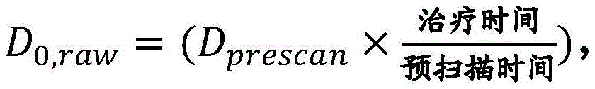

Wherein the dose calculation matrix a, the radiation excitation matrix RFM and the biological excitation zone mask BFZ are as described above. Based on the acquired imaging data, the radiation applied to the target region (e.g., biological excitation region or radiation excitation region) in a first pass can be calculated as follows:

image data x acquired during a first shuttle pass 1 Can be part images, for example, including one or more LORs (for image data acquired using a PET detector), one or more 2-D projection X-ray images (for image data acquired using a CT detector), and/or sub-samples in k-space (for image data acquired using an MRI detector). Although treatment planning parameters (e.g., RFM, BFZ) may specify the radiation flux D 1,raw Delivered to the target area, but the normalization factor and damping factor can be adjusted (i.e., scaled or normalized) by D 1,raw To reflect real-time treatment conditions during the session and/or to compensate for imaging data x acquired during the first shuttle pass 1 Variations and/or distortions in the image. D 1,raw May be a calculated radiation flux (e.g., having continuous flux values) or a segmented radiation flux (e.g., having discrete flux values or levels), where the segmented radiation flux may include flux values representing flux values deliverable by the radiation therapy system.
The method (840) may further include: calculating (852) a predicted cumulative flux (D) based on imaging data acquired by summing the N passes during the first pass 1,predicted cumulative) Wherein by calculating D plan Calculating (854) a normalization factor k for a second pass of radiation delivery from a difference between total flux emitted in the first pass and a ratio of the difference to a predicted cumulative flux 2 And applying (856) a second pass of radiation while acquiring imaging data, wherein based on the acquired imaging data and a normalization factor k 2 Calculating the emitted radiation flux D 2,calc . A predicted cumulative flux may be calculated (852) based on imaging data acquired during the first shuttle pass:
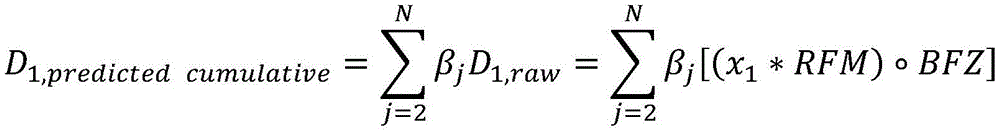
a normalization factor k for the second shuttle pass may be calculated 854 by taking the difference between the planned radiation flux or dose and the flux emitted in the first shuttle pass, normalizing according to the predicted cumulative flux 2 :
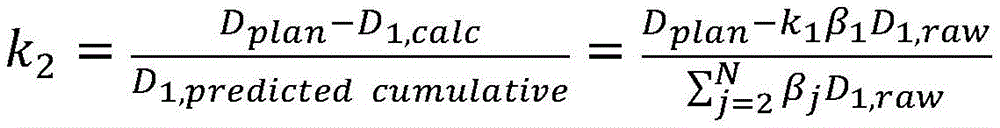
Thus, radiation applied to the target region (e.g., biological excitation region or radiation excitation region) in the second shuttle pass can be calculated based on imaging data acquired during the second shuttle pass as follows:

wherein image data x acquired during the second shuttle pass 2 May be a partial image, for example, including one or more LORs (for image data acquired with a PET detector), one or more 2-D projection X-ray images (for image data acquired with a CT detector), and/or subsampling in k-space (for image data acquired with an MRI detector), as previously described and as described in detail herein. D 2,raw May be a calculated radiation flux (e.g., having continuous flux values) or a segmented radiation flux (e.g., having discrete flux values or levels), where the segmented radiation flux may include flux values representing flux values deliverable by the radiation therapy system.
In some variations, dose values derived from pre-scan images may be used to calculate normalization factors for a first shuttle pass, while flux values (optionally, segmentation flux values, including any flux segmentation errors) may be used to calculate normalization factors for successive shuttle passes. Dose calculations may be more computationally intensive than flux calculations (since flux may be calculated by multiplying image data with a radiation excitation matrix, whereas dose calculations may involve additional multiplication with a dose calculation matrix), and thus it may be preferable for some radiation treatment systems to use radiation flux instead of radiation dose to calculate normalization factors during a treatment session, so that delays between imaging data acquisition and radiation delivery are reduced. Since the first normalization factor is calculated before the therapeutic beam is turned on, the radiation therapy system can be computationally available to calculate the first normalization factor based on the dose value derived from the pre-scan image. Some variations of radiation therapy systems may include one or more processors with greater computational power, in which case the normalization factor may be calculated using dose values derived from imaging data acquired during the treatment session. Alternatively or additionally, all normalization factors may be calculated based on flux values derived from image data acquired during the treatment session.
Fig. 9A-9D are simulated dose-volume graphs or histograms (DVH) depicting a method of radiation delivery to a planned target area (PTV) and bio-excitation zone (BFZ) area over four couch shuttles using one or more line normalization methods described herein. The BFZ region includes the PTV and the edge around the PTV. Fig. 9A depicts DVH curves after the first shuttle pass. The planned DVH of the PTV is represented by line (903), the maximum DVH limit (i.e., the upper therapeutically acceptable threshold) is represented by line (905), and the minimum DVH limit (i.e., the lower therapeutically acceptable threshold) is represented by line (907). The predicted delivered dose to the PTV is represented by the delivered DVH line (901). Similarly, the planned DVH for the BFZ region is represented by line (904), the maximum DVH limit (i.e., the upper therapeutically acceptable threshold) is represented by line (906), and the minimum DVH limit (i.e., the lower therapeutically acceptable threshold) is represented by line (908). The predicted delivered dose to the BFZ region is represented by the delivered DVH line (902). After the first shuttle pass, the predicted DVH curve (901) of the PTV exceeds the planned DVH curve (905) of the PTV and falls outside of the maximum DVH limit (905). Similarly, the predicted DVH curve (902) for the BFZ region exceeds the predicted DVH curve (904) for the BFZ region and falls outside of the maximum DVH bounds (906). As the radiation delivered to the PTV and BFZ regions accumulates on multiple shuttling passes, fig. 9B depicts the same DVH curves as in fig. 9A after the second shuttling pass, fig. 9C depicts the DVH curves after the third shuttling pass, and fig. 9D depicts the DVH curves after the fourth shuttling pass, it can be seen how the delivered DVH curves (PTV DVH 909 and BFZ region DVH 910) converge towards the planned DVH curves (PTV DVH 903 and BFZ region DVH904) and/or remain within the range defined by the maximum and minimum DVH curves of the PTV and BFZ regions, respectively.
Pipeline normalization with negative flux values
In some variations, when calculating the radiation flux for delivery, what is calculated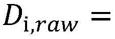
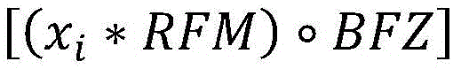 The values may result in negative radiation flux values. Negative radiation flux values may not be deliverable by the radiation therapy system in the same shuttle pass, however if such negative flux values are cleared and/or ignored, the cumulative delivered radiation may deviate significantly from the planned flux or dose value. A variation of the method for processing negative flux values accumulated in one shuttle pass may include merging negative flux values into the next shuttle pass where they may be combined with non-negative flux values. The next flux value may be a positive value and may therefore be deliverable in one or more subsequent shuttle passes. In some variations, the negative flux values in one shuttle pass may be incorporated into the calculation of the predicted cumulative flux to be delivered on the remaining shuttle passes and used to normalize D plan And D i,calc (i.e., the total cumulative delivered radiation in the treatment session until the next shuttle pass). FIG. 10 depicts a variation of a method in which the shuttle is usedThe negative flux values of radiation encountered during radiation delivery incorporated into previous passes are applied during shuttle passes by normalization factors calculated prior to commencement, modified or adjusted. The method (1000) may include: applying (1002) an i-th pass of radiation while acquiring imaging data, wherein based on the acquired imaging data and the calculated normalization factor k i To calculate the emitted radiation flux; calculating (1004) a predicted cumulative flux based on imaging data acquired during the first pass by summing the N passes, including negative flux values, if any; calculating a normalization factor k for the next pass based on the predicted cumulative flux i+1 (ii) a And applying (1008) an (i +1) th pass of radiation while acquiring imaging data, wherein based on the acquired imaging data and the calculated normalization factor k i+1 The emitted radiation flux is calculated. Optionally, the method (1000) may further include repeating the calculation of the normalization factor and the application of the radiation for
 i 1. The predicted cumulative flux may incorporate negative flux values as follows:

by merging negative flux values into D i,predicted cumulative In the next shuttle pass k i Because of D, this negative flux is taken into account in the generation of i,predicted cumulative Is used to normalize the difference between the planned and delivered radiation flux.
11A-11B are simulated DVH plots depicting the results of two radiation delivery methods in four couch shuttles up to a planned target area (PTV) and a biological excitation zone (BFZ). Figure 11A depicts the results of radiation delivery to the PTV and BFZ regions (as described above) when negative flux values are incorporated into the predicted cumulative flux values and included in the calculation of the normalization factor k. The planned DVH curve of the PTV is represented by line (1101), the maximum DVH curve is represented by line (1103), and the minimum DVH curve is represented by line (1105). The delivery DVH curve of the PTV is represented by line (1107), and viewed along the falling edge of the DVH curve, the delivery DVH curve of the PTV lies within the minimum and maximum DVH boundaries. Similarly, for the BFZ region, the planned DVH curve for the BFZ region is represented by line (1102), the maximum DVH curve is represented by line (1104), and the minimum DVH curve is represented by line (1106). The delivery DVH curve for the BFZ region is represented by line (1108), and as viewed along the falling edge of the DVH curve, the delivery DVH curve for the BFZ lies within the minimum and maximum DVH boundaries. In contrast, fig. 11B depicts the results of radiation delivery to the PTV and BFZ regions (as previously described) when negative flux values are ignored. The planned DVH curve of the PTV is represented by line (1101'), the maximum DVH curve is represented by line (1103'), and the minimum DVH curve is represented by line (1105 '). The delivery DVH curve of the PTV is represented by line (1107'), and as can be seen from the graph, the delivery DVH curve of the PTV does not lie within the boundary defined by the minimum and maximum DVH curves. Similarly, for the BFZ region, the planned DVH curve for the BFZ region is represented by line (1102'), the maximum DVH curve is represented by line (1104'), and the minimum DVH curve is represented by line (1106 '). The delivery DVH curve for the BFZ region is represented by line (1108'), and as can be seen in the graph, the delivery DVH curve for the BFZ does not lie within the boundary defined by the minimum and maximum DVH curves. The inclusion of a negative flux value in the calculation of the normalization factor may be incorporated into any of the methods described herein.
The pipeline normalization method for radiation delivery described herein may use an average of the planned flux (or dose) to constrain the average of the delivered flux (or dose). This may help the radiation therapy system deliver radiation with an average flux that converges to an average planned flux, which may help address motion and/or imaging distortions encountered during the treatment session. Figures 12A-12C, 13A-C, and 14A-C depict multiple views of a planned dose distribution, a delivered dose distribution over four shuttling passes, and a gamma metric, respectively, from multiple planes. The gamma (gamma) metric can be calculated as the square root of the sum of the squares of the consistent Distance (DTA) and the dose percentage difference (DD) between the two dose distributions. One of the dose distributions may be defined as a reference dose distribution (usually the ground truth), while the other may be defined as an estimated dose distribution. The established value of DTA may be 3mm, and DD may be 3%. The gamma metric may be calculated first for all voxel pairs in the two dose distributions, and the pass value may be defined as the value of gamma < ═ 1, and the failure is defined as the value of gamma > 1. The gamma pass rate can be calculated as the percentage of voxels in the treatment volume that are assessed by gamma. The treatment volume may be generally defined as the voxels of the reference dose distribution that receive more than 10% of the prescribed dose. Fig. 12A, 13A, and 14A depict projections of dose distributions on the IEC-Z/IEC-X plane (i.e., the plane orthogonal to the direction of motion of the couch), fig. 12B, 13B, and 14B depict projections of dose distributions on the IEC-Z/IEC-Y plane, and fig. 12C, 13C, and 14C depict projections of dose distributions on the IEC-Y/IEC-X plane (i.e., the plane orthogonal to the treatment beam, "line of sight of the beam"). As can be seen in fig. 14A-C, the gamma metric pass rate (i.e., gamma value less than or equal to 1) exceeds 99% when the radiation delivery based on the imaging data acquired during the treatment session is adjusted or modified using the normalization factor generated using one or more of the methods described herein. The region with a gamma metric exceeding 1 (as indicated by arrow (1400)) constitutes less than 1% of the total distribution shown in fig. 14A-14C. Fig. 14D is a graph depicting cumulative flux as a function of beam station for a treatment session with four shuttling passes. Each of the predictions in the predicted passes is calculated as the sum of the predicted flux and the delivered flux of the remaining passes. What is delivered is the final flux delivered to the tumor site. Each beam station is a predetermined couch position or step along the IEC-Y axis in which the couch may be stopped while the therapeutic radiation beam is activated and radiation is being applied to the patient. While the couch is moving between the beam stations, the therapeutic radiation beam is off (i.e., not activated). The line with the square emphasis number represents the planned flux, and the line with the cross-shaped emphasis number represents the flux delivered after four shuttle passes. As shown here, the average delivered cumulative flux converges towards the average of the planned flux for each incremental shuttle pass. Although the examples described herein include applying radiation over four shuttling passes, it is understood that the number of shuttling passes over a treatment session may vary and may range from 2 to 100 shuttling passes, e.g., 4 shuttling passes, 6 shuttling passes, 7 shuttling passes, 8 shuttling passes, 10 shuttling passes, 12 shuttling passes, etc.
Treatment interruption
A "make-up" segment may be executed if the treatment session is incomplete or interrupted (e.g., due to patient discomfort or illness, system component failure, etc.). The supplemental segment may be a completely new treatment session or segment (e.g., requiring new patient settings), or simply a continuation of the point incomplete segment at which the interruption occurred (e.g., requiring no new patient settings). If the complementing segment requires a new patient setting, different setting errors may lead to so-called domain connectivity errors, which may lead to under-or overdosing of the tumor target region and/or critical structures. A similar approach to that described above and shown in fig. 6 may be used to mitigate connection errors. The flux or dose delivered to the patient until the interruption occurs can be calculated. The calculated delivered flux and/or dose may be compared to a planned flux and/or dose. The flux and/or dose difference Δ f between the delivered and planned flux and/or dose can be used to update the RFM. The flux Δ f can then be delivered to the patient in a later treatment session or segment using the updated RFM.
A variation of the method for continuing radiation therapy after the interruption, wherein the patient remains on the table or couch before and after the interruption (i.e., the interruption therapy session is continued using the same patient setup parameters and pre-scan images), may include the steps of: the interrupted shuttling pass is continued by moving the patient platform to the beam station where the interruption occurred, and radiation delivery is resumed using the same normalization factor as was used prior to the interruption, and a normalization factor for the next shuttling pass is calculated based on the imaging data acquired prior to the interruption and the imaging data acquired after the interruption. Can be obtained by taking D plan The difference between the sum of the radiation delivered during the completed shuttle pass, the partial shuttle pass before the interruption and the partial shuttle pass resumed after the interruption, and if each of the future shuttle passes delivers and delivers in the interrupted passThe same amount of radiation (i.e., radiation delivered during the partial shuttle pass before the interruption and the partial shuttle pass resumed after the interruption) is then normalized to the difference in the predicted cumulative flux to be delivered to calculate a normalization factor for the shuttle pass after the interruption. For example, for a treatment session with a total of N shuttle passes and an interruption in the mth pass, the factor k is normalized i The following can be calculated:
D i-1,calc is defined as the delivered dose of i-1 passes as previously defined. The molecule is calculated as D for all previous passes plan And D i-1,calc The difference between the sums of (a) and (b).
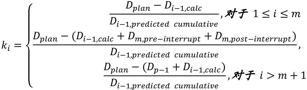
Wherein D p-1 =(D i-1,calc +D m,pre-interrupt ) And D plan 、D i,calc And so on as previously described.
Fig. 15A depicts a variation of the radiation delivery method when there has been an interruption during the shuttle pass and the patient remains on the platform to continue the interrupted treatment session (i.e., without a new pre-scan image). The method (1500) may include: calculating (1502) a cumulative radiation dose (D) to be applied to the patient until the treatment is interrupted in the mth pass of the total of N shuttling passes delivered_before_interrupt ) Storing (1504) the cumulative radiation dose D delivered_before_interrupt Normalization factor k for mth pass m And a patient table position at which treatment was interrupted in the system memory, and resuming the mth pass of radiation delivery (1506) by moving the patient table to the treatment interrupted position (e.g., beam station) and emitting a radiation flux, wherein the emitted flux is scaled by k m . The radiation delivered in the recovered mth fraction pass can be calculated as follows:

the method (1500) may include: calculating (1508) a predicted cumulative flux based on imaging data acquired during the m-th pass by summing the N passes, calculating (1510) a normalization factor k for a next pass based on the predicted cumulative flux m+1 Applying (1512) an (m +1) th pass of radiation while acquiring imaging data, wherein based on the acquired imaging data and the calculated normalization factor k m+1 Calculating the emitted radiation flux and calculating (1514) a normalization factor k m+2 And applying an (m +2) th pass of radiation based on imaging data acquired during the (m +2) th pass until N passes have been completed. The predicted cumulative flux may be calculated (1508) as follows:

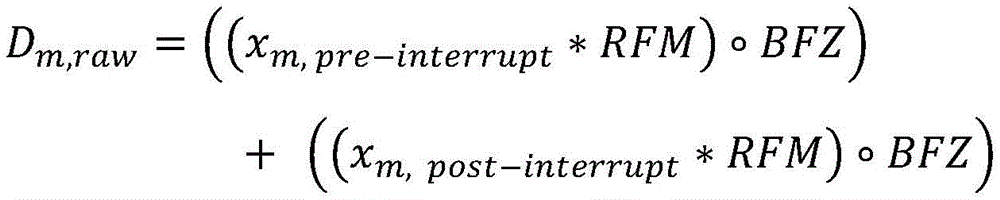
Normalization factor k m+1 May be calculated as follows (1510):

for example, if radiation delivery is interrupted in a second shuttle pass (no new setup or new pre-scan image is required), the normalization factor k may be used 2 The second shuttle pass is resumed (i.e., the same as before the interruption), and the normalization factor for the subsequent shuttle passes can be calculated as follows:

Fig. 16 is a graph depicting cumulative flux as a function of beam station for a treatment session with four shuttling passes, where treatment is interrupted at the second shuttling pass, with various interruption characteristics for assessing and characterizing the accuracy of the above-described method for treating treatment interruptions, compared to treatment sessions without any interruption (lines with cross-shaped emphasis). The damping factor used for this simulation has a value (α ═ 1/1.2). The lines with square emphasis numbers represent the planned flux, and the lines with cross-shaped emphasis numbers represent the flux delivered after four shuttle passes without interruption. The line with the diamond shaped emphasis represents the flux delivered after four shuttling passes with a single break midway through the second shuttling pass. The line with the star-shaped emphasis represents the flux delivered after four shuttle passes with a single interruption at the end of the second shuttle pass when the couch is changing direction between the second and third passes. The line with the circular emphasis represents the flux delivered after four shuttle passes with three interruptions. As shown in this figure, updating the normalization factor with the flux emitted before and after the interruption helps to converge the average of the cumulative delivered radiation flux to the average planned radiation flux despite the interruption in the treatment session. The flux curves for treatment segments with interruptions (i.e., lines with diamond, star, and circular emphasis) followed closely with the curves for treatment segments without interruptions (i.e., lines with cross emphasis).
In some variations, radiation delivery cannot (or is not desired to) be resumed in the same session, and the patient may be removed from the system and scheduled for another occasion to resume treatment. For example, the patient may feel too uncomfortable to perform radiation delivery on a particular day and/or the components of the radiation therapy system may not work within specified tolerances and may not be able to be calibrated to the patient in the bunker. When the patient returns to resume radiation delivery, new settings and new pre-scan images may be acquired. In some variations, the patient platform may be moved to a position and/or beam station where an interruption in a previous treatment occurred. In calculating the normalization factor for resuming radiation delivery, the radiation delivery method may take into account new settings and/or pre-scan images and the radiation flux delivered in the previous interruption session. FIG. 15B depicts a diagram in which the output can be adjusted by a normalization factorA variation of the delivered radiation delivery method, the normalization factor being derived based at least in part on the delivered radiation flux in the previous treatment session, and the pre-scan image acquired for the current session is depicted in fig. 15B. The method (1520) may include calculating (1522) up to an mth pass (D) of the total of N passes delivered_before_interrupt ) The cumulative radiation dose applied to the patient until treatment is interrupted, and the cumulative radiation dose D is stored (1524) in system memory delivered_before_interrupt Normalization factor k for mth pass m And acquiring (1526) a new pre-scan image (e.g., a PET and/or CT image X) of the patient when treatment is discontinued and at a patient table position (e.g., a position indexed along the IEC-Y axis and/or beam station) after the patient returns to the radiation treatment system p_prescan ) And is based on X p_prescan Calculating a normalization factor k p_m And by moving the patient table to a position to interrupt treatment and emitting radiation flux (with the radiation flux scaled by k) p_m ) To resume (1528) radiation delivery in the mth pass. The normalization factor k can be calculated (1526) as follows p_m :
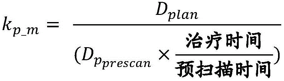
Wherein D plan 、β j As described above, and D pprescan Is based on a new pre-scan image X p_prescan The calculated radiation flux. The radiation flux delivered (1528) to resume the interrupted mth shuttle pass may be determined (1528) as follows:

wherein x m,post-interrupt Is the imaging data acquired in the mth shuttle pass after the interruption. The method (1520) may further include: calculating (1530) a predicted cumulative flux based on imaging data acquired during the m-th pass by summing the N passes, calculating (15) a predicted cumulative flux based on the predicted cumulative flux32) Normalization factor k for the next pass m+1 Applying (1534) the (m +1) th pass of radiation while acquiring imaging data, wherein based on the acquired imaging data and the calculated normalization factor k m+1 Calculating the emitted radiation flux and optionally calculating (1536) a normalization factor k m+2 And applying an (m +2) th pass of radiation based on imaging data acquired during the (m +2) th pass until N passes have been completed. The predicted cumulative flux may be calculated 1530 as follows:


Wherein x m,pre-interrupt Including imaging data acquired in the mth shuttle pass before the interruption, x m,post-interrupt Including imaging data acquired in the mth shuttle pass after the interruption (i.e., resuming the interrupted shuttle pass). Normalization factor k m+1 It can be calculated as follows (1532):

wherein D delivered_before_interrupt Is the cumulative radiation flux delivered prior to the interrupted shuttling pass, and D partial mthpass Is the radiation flux delivered during the interrupted pass of the recovery (e.g., the portion of the m-th pass not delivered due to the interruption).
Controller
A system (e.g., treatment planning system, radiation therapy system) that may be configured to deliver therapeutic radiation to a patient may include a controller in communication with an imaging system and/or a therapeutic radiation source and/or a multi-leaf collimator and/or a gantry of the radiation therapy system. The controller may include one or more processors and one or more machine readable memories in communication with the one or more processors, which may be configured to perform or execute any of the methods described herein (e.g., the methods described and depicted in fig. 4, 5, 6, 7, 8A-8C, 10, 15A-15B). The controller of the radiation therapy system may be connected to other systems through wired or wireless communication channels. In some variations, the controller of the treatment planning system may be located in the same or different room as the patient. For example, the controller may be coupled to a patient platform or disposed on a cart or medical cart adjacent to the patient and/or operator.
The controller may be implemented in association with numerous general purpose or special purpose computing systems or configurations. Various exemplary computing systems, environments, and/or configurations that may be suitable for use with the systems and devices disclosed herein may include, but are not limited to, software or other components embodied within or on a personal computing device, a network device, a server, or a server computing device, such as routing/connection components, portable (e.g., handheld) or laptop computer devices, multiprocessor systems, microprocessor-based systems, and distributed computing networks.
Examples of portable computing devices include smart phones, cellular phones, tablet computers, tablet handsets (personal computing devices larger than smart phones but smaller than tablet computers), and the like.
Processor with a memory for storing a plurality of data
In some embodiments, a processor may be any suitable processing device configured to execute and/or execute a set of instructions or code and may include one or more data processors, image processors, graphics processing units, physical processing units, digital signal processors, and/or central processing units. The processor may be, for example, a general purpose processor, a Field Programmable Gate Array (FPGA), an Application Specific Integrated Circuit (ASIC), or the like. The processor may be configured to run and/or execute application processes and/or other modules, processes, and/or functions associated with the system and/or networks associated therewith. Basic device technologies may be provided in a variety of component types, for example, Metal Oxide Semiconductor Field Effect Transistor (MOSFET) technologies such as Complementary Metal Oxide Semiconductor (CMOS), bipolar technologies such as Emitter Coupled Logic (ECL), polymer technologies (e.g., silicon-conjugated polymers and metal-conjugated polymer-metal structures), analog and digital hybrids, and so forth.
Memory device
In some embodiments, the memory may include a database, and may be, for example, Random Access Memory (RAM), memory buffers, hard drives, erasable programmable read-only memory (EPROM), electrically erasable read-only memory (EEPROM), read-only memory (ROM), flash memory, and the like. The memory may store instructions to cause the processor to perform modules, processes, and/or functions associated with the system, such as one or more of treatment planning, full or high SNR images, partial or low SNR images, flux map calculations based on the treatment planning and/or clinical goals, flux map segmentation into radiation treatment system instructions (e.g., that may direct the operation of the gantry, therapeutic radiation source, multi-leaf collimator, and/or any other component of the radiation treatment system and/or diagnostic or treatment planning system), normalization factors, damping factors, calculated and/or measured quantities of delivered or emitted radiation flux or dose, patient table or couch position, and image and/or data processing associated with the treatment planning and/or delivery.
Some embodiments described herein relate to a computer storage product with a non-transitory computer-readable medium (which may also be referred to as a non-transitory processor-readable medium) having instructions or computer code thereon for performing various computer-implemented operations. The computer-readable medium (or processor-readable medium) is non-transitory in the sense that the computer-readable medium does not include a transitory propagating signal per se (e.g., a propagating electromagnetic wave carrying information on a transmission medium such as space or cable). The media and computer code (also can be referred to as code or algorithms) may be designed and constructed for one or more specific purposes. Examples of non-transitory computer readable media include, but are not limited to: magnetic storage media such as hard disks, floppy disks, and magnetic tape; optical storage media such as compact discs/digital video discs (CD/DVD); compact disc read only memory (CD-ROM) and holographic devices; magneto-optical storage media such as optical disks; solid state storage devices, such as Solid State Drives (SSDs) and Solid State Hybrid Drives (SSHDs); a carrier signal processing module; and hardware devices that are specially configured to store and execute program code, such as Application Specific Integrated Circuits (ASICs), Programmable Logic Devices (PLDs), read-only memory (ROMs), and Random Access Memory (RAM) devices. Other embodiments described herein relate to a computer program product that may include, for example, the instructions and/or computer code disclosed herein.
The user interface may serve as a communication interface between an operator or clinician and the radiation therapy system. The user interface may include an input device and an output device (e.g., a touchscreen and a display) and be configured to receive input data and output data from one or more of the support arm, the external magnet, the sensor, the delivery device, the input device, the output device, the network, the database, and the server. Sensor data from one or more sensors may be received by a user interface and output by one or more output devices visually, audibly, and/or through tactile feedback. As another example, a user may receive operator controls of an input device (e.g., joystick, keyboard, touch screen) and then processed by the processor and memory for use in a user interface to output control signals to radiation treatment system components (e.g., gantry, MLC, therapeutic radiation source, imaging system, PET detector, etc.).
Some variations of radiation therapy systems for delivering therapeutic radiation may include a display device that may allow an operator to view graphical and/or textual representations of a flux map and/or a dose distribution and/or a region of interest and/or a volume of interest and/or a patient anatomical image and/or patient data (e.g., physiological and/or biological), a DVH curve, a dose graph, and/or the like. In some variations, the output device may include a display device including at least one of a Light Emitting Diode (LED), a Liquid Crystal Display (LCD), an electroluminescent display (ELD), a Plasma Display Panel (PDP), a Thin Film Transistor (TFT), an Organic Light Emitting Diode (OLED), an electronic paper/electronic ink display, a laser display, and/or a holographic display.
Communication
In some embodiments, the treatment planning system and/or the radiation therapy system may communicate with other computing devices via, for example, one or more networks, each of which may be any type of network (e.g., wired network, wireless network). A wireless network may refer to any type of digital network that is not connected by any type of cable. Examples of wireless communications in a wireless network include, but are not limited to, cellular, radio, satellite, and microwave communications. However, wireless networks may be connected to wired networks to interface with the internet, other carrier voice and data networks, service networks, and personal networks. Wired networks are typically carried by twisted copper pairs, coaxial cable, and/or fiber optic cable. There are many different types of wired networks, including Wide Area Networks (WANs), Metropolitan Area Networks (MANs), Local Area Networks (LANs), internet access area networks (ias), Campus Area Networks (CANs), Global Area Networks (GANs), such as the internet, and Virtual Private Networks (VPNs). Hereinafter, a network refers to any combination of wireless, wired, public, and private data networks interconnected typically by the internet to provide a unified networking and information access system.
Cellular communication may encompass technologies such as GSM, PCS, CDMA or GPRS, W-CDMA, EDGE or CDMA2000, LTE, WiMAX, and 5G network standards. Some wireless network deployments incorporate networks from multiple cellular networks, or use a mix of cellular, Wi-Fi, and satellite communications. In some embodiments, the systems, apparatuses, and methods described herein may include radio frequency receivers, transmitters, and/or optical (e.g., infrared) receivers and transmitters to communicate with one or more devices and/or networks.
While various inventive variations have been described and illustrated herein, those of ordinary skill in the art will readily envision a variety of other means and/or structures for performing the function and/or obtaining the results and/or one or more of the advantages described herein, and each such variation and/or modification is deemed to be within the scope of the inventive embodiments described herein. More generally, those skilled in the art will readily appreciate that all parameters, dimensions, materials, and configurations described herein are meant to be exemplary and that the actual parameters, dimensions, materials, and/or configurations will depend upon the specific application or applications for which the teachings of the present invention is/are used. Those skilled in the art will recognize, or be able to ascertain using no more than routine experimentation, many equivalents to the specific inventive variations described herein. It is, therefore, to be understood that the foregoing modifications are presented by way of example only and that changes may be practiced within the scope of the appended claims and their equivalents other than as specifically described and claimed. Inventive variations of the present disclosure are directed to each individual feature, system, article, material, kit, and/or method described herein. In addition, any combination of two or more such features, systems, articles, materials, kits, and/or methods, if such features, systems, articles, materials, kits, and/or methods are not mutually inconsistent, is included within the scope of the present disclosure.
Claims (42)
1. A radiation delivery system for delivering radiation during a treatment session, the radiation delivery system comprising:
a frame;
a therapeutic radiation source mounted on the gantry;
an imaging system mounted on the gantry; and
a controller in communication with the gantry, the radiation source, and the imaging system, wherein the controller is configured to:
acquiring imaging data x of a patient positioned on a table using the imaging system i ;
Delivering a treatment-planned volume of radiation D to the patient using the radiation source plan Wherein the radiation dose is derived from the acquired imaging data;
stopping the application of radiation to the patient;
storing the amount of radiation D applied to the patient before stopping applying radiation delivered , pre-interrupt And the position of the platform when stopping the application of radiation; and
restoring orientation while acquiring additional imaging dataThe patient delivers radiation, wherein a second amount of radiation delivered to the patient is derived from the additional imaging data and is according to D plan And D delivered,pre-interrupt The difference between them is adjusted.
2. The system of claim 1, wherein resuming the application of radiation comprises: moving the patient platform back to the position of the platform at the time radiation delivery was stopped.
3. The system of claim 1, wherein the amount of radiation applied before radiation application is stopped is a first amount of radiation, and imaging data x acquired during the treatment session before radiation application is stopped is derived from i And (6) obtaining.
4. The system of claim 3, wherein the first radiation dose is determined by comparing the acquired imaging data x i Multiplying with a radiation excitation matrix RFM and applying a biological excitation zone mask BFZ, wherein the RFM and the BFZ are calculated during a treatment planning session.
5. The system of claim 4, wherein applying a volume of radiation to the patient comprises: in acquiring a first set of imaging data x 1 While applying a first pass of radiation while moving the patient platform through the therapeutic radiation beam plane from a first position to a second position, wherein the first set of imaging data x is obtained by moving the first set of imaging data x 1 Multiplying with the radiation excitation matrix RFM and applying the biological excitation zone mask BFZ to obtain D 1,raw And by a first normalization factor k 1 Zoom D 1,raw Deriving said amount of radiation (D) emitted during said first pass 1,calc )。
6. The system of claim 5, wherein the first normalization factor k 1 Calculated by the following way:
by the period of the treatment sessionMultiplying said pre-scan image of said patient acquired in-between with said radiation excitation matrix RFM and applying said bio-excitation zone mask BFZ to calculate an amount of radiation D 0,raw ;
By mixing D 0,raw Multiplying the total number of radiation passes N in the treatment session by a cumulative predicted dose D 0,predictedcumulative (ii) a And
get D plan And the cumulative predicted dose D 0,predictedcumulative A ratio of (a) to (b).
7. The system of any one of claims 5 and 6, wherein applying a radiation dose to the patient further comprises: in acquiring the second set of imaging data x 2 While moving the patient platform through the therapeutic radiation beam plane from the second position to the first position, applying a second pass of radiation by moving the second set of imaging data x 2 Multiplying with the radiation excitation matrix RFM and applying the biological excitation zone mask BFZ to obtain D 2,raw And by a second normalization factor k 2 Zoom D 2,raw Deriving the amount of radiation (D) emitted during the second pass 2 , calc )。
8. The system of claim 7, wherein stopping the application of radiation to the patient comprises stopping the application of radiation during the second pass of radiation, and wherein resuming the application of radiation to the patient comprises: acquiring a restored set of imaging data x 2,resumed And transmitting a set of imaging data x obtained by recovering said data 2,resumed Multiplying with the radiation excitation matrix RFM and applying the biological excitation zone mask BFZ to obtain D 2,raw,post-interrupt And by said second normalization factor k 2 Zoom D 2,raw,post-interrupt Derived amount of radiation, wherein the amount of radiation applied before stopping applying radiation is D 2,raw,pre-interrupt 。
9. The system of claim 8, wherein resuming the application of radiation to the patient further comprises: in acquiring a third set of imaging data x 3 While moving the patient platform through the therapeutic radiation beam plane from the first position to the second position, a third pass of radiation is applied, wherein the third set of imaging data x is obtained by moving the third set of imaging data x 3 Multiplying with the radiation excitation matrix RFM, applying the biological excitation zone mask BFZ, and passing a third normalization factor k 3 Scaling to derive the amount of radiation emitted during the third pass.
10. The system of claim 9, wherein the third normalization factor k 3 Calculated by the following way:
calculating D plan With the amount of radiation D applied in said first pass 1,calc And the amount of radiation D applied in said second pass 2,calc The difference between the cumulative radiation doses of;
by mixing (D) 2,raw,pre-interrupt +D 2,raw,post-interrupt ) Multiplying by N-3 to calculate the cumulative predicted dose D 2,predictedcumulative (ii) a And
is taken from (D) plan –(D 1,calc +D 2,calc ) And the cumulative predicted dose D) 2,predictedcumulative The ratio of (a) to (b).
11. The system of claim 7, wherein stopping the application of radiation to the patient comprises stopping the application of radiation during the second pass of radiation, and wherein resuming the application of radiation to the patient comprises:
acquiring a second pre-scan image of the patient;
moving the patient platform back to the position of the patient platform at which the radiation application was stopped; and
acquiring a restored set of imaging data x 2,resumed And transmitting a set of imaging data x by recovering said 2,resumed And said putMultiplying by a radio-excitation matrix RFM and applying said bio-excitation zone mask BFZ to obtain D 2,raw,post-interrupt And by the recovered normalization factor k 2_resumed Zoom D 2,raw,post-interrupt Derived amount of radiation, wherein the amount of radiation applied before stopping applying radiation is D 2,raw,pre-interrupt 。
12. The system of claim 11, wherein the recovered normalization factor k 2_resumed Calculated by the following way:
calculating an amount of radiation D by multiplying the second pre-scan image of the patient with the radiation excitation matrix RFM and applying the biological excitation zone mask BFZ 2,raw,post-interrupt ;
By mixing (D) 2,raw,pre-interrupt +D 2,raw,post-interrupt ) Multiplying by N-2 to calculate the cumulative predicted dose D 2,predictedcumulative (ii) a And
get D plan And the cumulative predicted dose D 2,predictedcumulative The ratio of (a) to (b).
13. The system of claim 12, wherein resuming the application of radiation to the patient further comprises: in acquiring a third set of imaging data x 3 While moving the patient platform through the therapeutic radiation beam plane from the first position to the second position, a third pass of radiation is applied, wherein the third set of imaging data x is obtained by moving the third set of imaging data x 3 Multiplying with the radiation excitation matrix RFM, applying the biological excitation zone mask BFZ, and passing a third normalization factor k 3 Scaling to derive the amount of radiation emitted during the third pass.
14. The system of claim 13, wherein the third normalization factor k 3 Calculated by the following way:
calculating D plan With the amount of radiation D applied in said first pass 1,calc And the amount of radiation D applied in said second pass 2,calc The difference between the cumulative radiation doses of;
by mixing (D) 2,raw,pre-interrupt +D 2,raw,post-interrupt ) Multiplying by N-3 to calculate the cumulative predicted dose D 2,predictedcumulative (ii) a And
get (D) plan –(D 1,calc +D 2,calc ) And the cumulative predicted dose D 2,predictedcumulative A ratio of (a) to (b).
15. A radiation delivery system, comprising:
a frame;
a therapeutic radiation source mounted on the gantry and configured to apply radiation in a radiation treatment beam plane;
a plurality of PET detectors mounted on the gantry;
a platform movable relative to the frame; and
a controller in communication with the gantry, the therapeutic radiation source, and the platform, the controller configured to acquire images of a patient on the platform, calculate a normalization factor based on the acquired images, and deliver radiation to the patient across multiple shuttling passes,
wherein, in each shuttle pass, the controller is configured to:
updating a radiation excitation matrix of the treatment plan using the calculated normalization factor;
moving the platform from a first predetermined position to a second predetermined position such that the target region of the patient traverses the radiation therapy beam plane at least once;
acquiring PET data using the PET detector;
delivering radiation to the patient based on the updated radiation excitation matrix and the acquired PET data;
calculating a flux delivered to the patient when the platform has moved to the second predetermined position;
calculating a flux difference between the flux delivered to the patient and a treatment plan flux; and
an updated normalization factor is calculated based on the flux difference.
16. The system of claim 15, wherein the PET detector is coplanar with the radiation therapy beam plane.
17. The system of claim 15, wherein the acquired image is a PET image.
18. The system of claim 17, wherein calculating the normalization factor comprises: calculating an average of the PET intensities of the target region in the acquired PET image.
19. The system of claim 15, wherein the number of shuttling passes is an even number.
20. The system of claim 15, wherein the number of shuttling passes is two or more.
21. The system of claim 15, wherein calculating an updated normalization factor includes calculating a mean flux value of the radiation emitted by the therapeutic radiation source.
22. The system of claim 15, wherein calculating an updated normalization factor includes calculating a ratio between an average planned dose value of radiation to the target region and an average delivered dose value of the radiation.
23. The system of claim 15, wherein delivering radiation based on the updated radiation excitation matrix and the acquired PET data comprises:
multiplying the updated radiation excitation matrix with imaging data derived from one or more lines of response (LORs) of the acquired PET data and applying a biological excitation location mask BFZ to derive a delivery flux map; and
generating radiation using the therapeutic radiation source according to the delivery flux map.
24. The system of claim 15, further comprising a movable jaw disposed above the therapeutic radiation source and a multi-leaf collimator coupled to the jaw, wherein the treatment beam plane is defined by a position of the movable jaw and a configuration of the multi-leaf collimator relative to the therapeutic radiation source.
25. The system of claim 24, wherein the controller is configured to move the movable jaw from a first jaw position to a second jaw position and back to the first jaw position when delivering radiation to the patient.
26. The system of claim 15, wherein the controller is configured to calculate a predicted dose and dose value histogram by adjusting the acquired image by the calculated normalization factor.
27. A radiation delivery system, comprising:
a frame;
a therapeutic radiation source, wherein a moveable jaw and a multi-leaf collimator are both disposed in a radiation beam path of the radiation source, and wherein a position of the moveable jaw and a configuration of the multi-leaf collimator relative to the radiation source define a treatment plane;
a radiation therapy system platform; and
a controller in communication with the gantry, the radiation source, and the radiation therapy system platform, the controller configured to:
(a) moving a patient positioned on the platform by moving the platform from a first predetermined position to a second predetermined position such that one or more target areas of the patient traverse the treatment plane; and
(b) delivering radiation to the patient with the radiation source as a portion of the one or more target areas traverses the treatment plane, wherein delivering the radiation includes moving the movable jaw from a first jaw position to a second position and back to the first jaw position while emitting radiation from the radiation source prior to moving to a next platform position.
28. The system of claim 27, wherein moving the platform comprises moving the platform in a series of predefined incremental patient platform positions, and wherein delivering radiation to the patient comprises delivering radiation at each platform position where the one or more target regions traverse the treatment plane.
29. The system of claim 27, wherein moving the platform comprises translating the platform along a longitudinal axis, and wherein moving the movable jaw comprises moving the jaw such that the treatment plane is offset along the longitudinal axis.
30. The system of claim 29, wherein moving the movable jaw offsets the treatment plane from about 1cm to about 12cm along the longitudinal axis.
31. The system of claim 30, wherein moving the movable jaw shifts the treatment plane at a speed from about 0.25cm/s to about 2 cm/s.
32. The system of claim 27, wherein the controller is configured to acquire an image of the patient prior to delivering radiation to the patient.
33. The system of claim 32, further comprising a plurality of PET detectors configured to acquire PET data including lines of response (LORs), and wherein delivering radiation to the patient includes multiplying a radiation excitation matrix of a treatment plan with imaging data derived from the one or more LORs and applying a biological excitation location mask BFZ to derive a delivery flux map and generating radiation using the therapeutic radiation source according to the delivery flux map.
34. The system of claim 32, wherein the acquired image is a PET image.
35. The system of claim 27, wherein the controller is configured to repeat steps (a) and (b) a preselected number of shuttling passes.
36. The system of claim 35, wherein the preselected number of shuttling passes is two or more.
37. A radiation delivery system, comprising:
a frame;
a therapeutic radioactive source; and
a controller in communication with the gantry and the radiation source, the controller configured to:
calculating a radiation flux delivered to a target region of a patient during a previous radiation delivery session;
comparing the delivered radiation flux to the target region and the treatment plan flux to the target region and calculating a flux difference;
calculating a radiation excitation matrix based on the calculated flux difference; and
delivering radiation to the patient in a subsequent radiation delivery session based on the computed radiation excitation matrix and PET data acquired during the subsequent radiation delivery session.
38. The system of claim 37, wherein comparing comprises: the average delivered radiation flux to the target region and the average treatment plan flux to the target region are compared, and a flux difference is calculated by taking the difference between the average delivered radiation flux and the average treatment plan flux.
39. The system of claim 37, wherein the PET data includes line of response (LOR) data.
40. The system of claim 15, wherein the number of shuttling passes varies depending on whether the delivered flux converges on the treatment plan flux.
41. The system of claim 15, wherein calculating an updated normalization factor comprises: delivering a dose value derived from the delivered flux using a dose calculation matrix, and updating the normalization factor based on the dose value such that radiation delivery satisfies a dose-based metric.
42. The system of claim 41, wherein the dose-based metric comprises a percentage-based dose coverage metric.
Applications Claiming Priority (4)
| Application Number | Priority Date | Filing Date | Title |
|---|---|---|---|
| US201762562212P | 2017-09-22 | 2017-09-22 | |
| US62/562,212 | 2017-09-22 | ||
| CN201880075453.7A CN111372653B (en) | 2017-09-22 | 2018-09-21 | Systems and methods for shuttle-mode radiation delivery |
| PCT/US2018/052272 WO2019060764A1 (en) | 2017-09-22 | 2018-09-21 | Systems and methods for shuttle mode radiation delivery |
Related Parent Applications (1)
| Application Number | Title | Priority Date | Filing Date |
|---|---|---|---|
| CN201880075453.7A Division CN111372653B (en) | 2017-09-22 | 2018-09-21 | Systems and methods for shuttle-mode radiation delivery |
Publications (1)
| Publication Number | Publication Date |
|---|---|
| CN115040796A true CN115040796A (en) | 2022-09-13 |
Family
ID=65807097
Family Applications (2)
| Application Number | Title | Priority Date | Filing Date |
|---|---|---|---|
| CN202210660569.5A Pending CN115040796A (en) | 2017-09-22 | 2018-09-21 | System and method for shuttle mode radiation delivery |
| CN201880075453.7A Active CN111372653B (en) | 2017-09-22 | 2018-09-21 | Systems and methods for shuttle-mode radiation delivery |
Family Applications After (1)
| Application Number | Title | Priority Date | Filing Date |
|---|---|---|---|
| CN201880075453.7A Active CN111372653B (en) | 2017-09-22 | 2018-09-21 | Systems and methods for shuttle-mode radiation delivery |
Country Status (5)
| Country | Link |
|---|---|
| US (5) | US10617888B2 (en) |
| EP (2) | EP3684468B1 (en) |
| JP (5) | JP6918388B2 (en) |
| CN (2) | CN115040796A (en) |
| WO (1) | WO2019060764A1 (en) |
Families Citing this family (16)
| Publication number | Priority date | Publication date | Assignee | Title |
|---|---|---|---|---|
| CN109152928B (en) | 2016-03-09 | 2021-05-28 | 反射医疗公司 | Method and system for calculating a fluence map for radiation therapy |
| JP7201243B2 (en) | 2016-11-15 | 2023-01-10 | リフレクション メディカル, インコーポレイテッド | System for Stimulated Emission High-Energy Photon Delivery |
| JP7178714B2 (en) | 2016-11-15 | 2022-11-28 | リフレクション メディカル, インコーポレイテッド | Radiation Therapy Patient Platform |
| WO2018093849A1 (en) | 2016-11-15 | 2018-05-24 | Reflexion Medical, Inc. | Methods for radiation delivery in emission-guided radiotherapy |
| CN115040796A (en) | 2017-09-22 | 2022-09-13 | 反射医疗公司 | System and method for shuttle mode radiation delivery |
| CN119701229A (en) | 2018-02-13 | 2025-03-28 | 反射医疗公司 | Beam station treatment planning and radiation delivery method |
| US12053645B2 (en) * | 2018-08-31 | 2024-08-06 | Mayo Foundation For Medical Education And Research | System and method for robust treatment planning in radiation therapy |
| US12109438B2 (en) * | 2018-12-26 | 2024-10-08 | Our United Corporation | Positioning method realized by computer, and radiotherapy system |
| WO2020133400A1 (en) * | 2018-12-29 | 2020-07-02 | 清华大学 | Tomography and image-guided radiotherapy device |
| WO2020257338A1 (en) * | 2019-06-17 | 2020-12-24 | Reflexion Medical, Inc. | Adaptive focus collimation of x-ray beams |
| EP4078607A1 (en) | 2019-12-20 | 2022-10-26 | Elekta AB (PUBL) | Adaptive dose accumulation algorithm |
| GB2598273B (en) * | 2020-05-01 | 2023-03-29 | Elekta ltd | Patient positioning for radiotherapy treatment |
| CA3211126A1 (en) * | 2021-02-24 | 2022-09-01 | Reflexion Medical, Inc. | Methods for optimizing treatment time and plan quality for radiotherapy |
| WO2022240894A1 (en) * | 2021-05-11 | 2022-11-17 | Celestial Oncology Inc. | Coupled robotic radiation therapy system |
| US12350523B2 (en) * | 2021-10-22 | 2025-07-08 | Viewray Systems, Inc. | MRI guided radiotherapy |
| WO2025184207A1 (en) * | 2024-02-27 | 2025-09-04 | Reflexion Medical, Inc. | Devices and methods for radiotherapy system alignment and calibration |
Family Cites Families (221)
| Publication number | Priority date | Publication date | Assignee | Title |
|---|---|---|---|---|
| US3794840A (en) | 1972-03-27 | 1974-02-26 | Charlotte Memorial Hospital | Method and apparatus for directing a radiation beam toward a tumor or the like |
| AU568793B2 (en) | 1985-07-26 | 1988-01-07 | National Starch & Chemical Corporation | Rmoistenable hot-melt adhesive of poly(alkyloxazoline) |
| US5351280A (en) | 1992-03-19 | 1994-09-27 | Wisconsin Alumni Research Foundation | Multi-leaf radiation attenuator for radiation therapy |
| JP3675816B2 (en) | 1993-06-09 | 2005-07-27 | ウイスコンシン アラムナイ リサーチ フオンデーシヨン | Dynamic beam smoothing device for radiation therapy |
| DE69425762T2 (en) | 1993-06-09 | 2001-04-26 | Wisconsin Alumni Research Foundation, Madison | Radiation therapy system |
| US5511549A (en) * | 1995-02-13 | 1996-04-30 | Loma Linda Medical Center | Normalizing and calibrating therapeutic radiation delivery systems |
| US5813985A (en) | 1995-07-31 | 1998-09-29 | Care Wise Medical Products Corporation | Apparatus and methods for providing attenuation guidance and tumor targeting for external beam radiation therapy administration |
| DE69737508T2 (en) | 1996-10-24 | 2007-11-29 | The Nomos Corp. | PLANNING AND DEVICE FOR PLANTING THE IRRADIATION DOSING |
| US6023494A (en) | 1996-12-19 | 2000-02-08 | General Electric Company | Methods and apparatus for modifying slice thickness during a helical scan |
| JP3926468B2 (en) | 1998-04-10 | 2007-06-06 | 株式会社日立製作所 | Proton irradiation direction determination support system |
| US6393096B1 (en) | 1998-05-27 | 2002-05-21 | Nomos Corporation | Planning method and apparatus for radiation dosimetry |
| EP1100587B1 (en) | 1998-08-06 | 2007-10-03 | Wisconsin Alumni Research Foundation | Radiotherapy verification system |
| US8788020B2 (en) | 1998-10-23 | 2014-07-22 | Varian Medical Systems, Inc. | Method and system for radiation application |
| US6937696B1 (en) | 1998-10-23 | 2005-08-30 | Varian Medical Systems Technologies, Inc. | Method and system for predictive physiological gating |
| US6621889B1 (en) | 1998-10-23 | 2003-09-16 | Varian Medical Systems, Inc. | Method and system for predictive physiological gating of radiation therapy |
| US6459769B1 (en) * | 1999-05-03 | 2002-10-01 | Sherwood Services Ag | Movable miniature multi-leaf collimator |
| US6490476B1 (en) | 1999-10-14 | 2002-12-03 | Cti Pet Systems, Inc. | Combined PET and X-ray CT tomograph and method for using same |
| US6455856B1 (en) | 2000-06-02 | 2002-09-24 | Koninklijke Philips Electronics N.V. | Gamma camera gantry and imaging method |
| US6504899B2 (en) | 2000-09-25 | 2003-01-07 | The Board Of Trustees Of The Leland Stanford Junior University | Method for selecting beam orientations in intensity modulated radiation therapy |
| US6661870B2 (en) | 2001-03-09 | 2003-12-09 | Tomotherapy Incorporated | Fluence adjustment for improving delivery to voxels without reoptimization |
| US6459762B1 (en) | 2001-03-13 | 2002-10-01 | Ro Inventions I, Llc | Method for producing a range of therapeutic radiation energy levels |
| FR2823679B1 (en) | 2001-04-23 | 2004-01-02 | Dyn R | METHOD AND DEVICE FOR DRIVING A RADIATION THERAPY UNIT FOR THE TREATMENT OF THORACIC TUMORS |
| US6965661B2 (en) | 2001-06-19 | 2005-11-15 | Hitachi, Ltd. | Radiological imaging apparatus and radiological imaging method |
| US7769430B2 (en) | 2001-06-26 | 2010-08-03 | Varian Medical Systems, Inc. | Patient visual instruction techniques for synchronizing breathing with a medical procedure |
| US20030036700A1 (en) | 2001-07-20 | 2003-02-20 | Weinberg Irving N. | Internal/external coincident gamma camera system |
| JPWO2003018131A1 (en) | 2001-08-24 | 2004-12-09 | 三菱重工業株式会社 | Radiotherapy equipment |
| WO2003018132A1 (en) | 2001-08-24 | 2003-03-06 | Mitsubishi Heavy Industries, Ltd. | Radiotherapeutic device |
| US6700949B2 (en) | 2001-09-25 | 2004-03-02 | Ge Medical Systems Global Technology Llc | Retractable collimator apparatus for a CT-PET system |
| US6888919B2 (en) | 2001-11-02 | 2005-05-03 | Varian Medical Systems, Inc. | Radiotherapy apparatus equipped with an articulable gantry for positioning an imaging unit |
| US20030128801A1 (en) | 2002-01-07 | 2003-07-10 | Multi-Dimensional Imaging, Inc. | Multi-modality apparatus for dynamic anatomical, physiological and molecular imaging |
| CA2478296A1 (en) | 2002-03-06 | 2003-09-18 | Tomotherapy Incorporated | Method for modification of radiotherapy treatment delivery |
| US6735277B2 (en) | 2002-05-23 | 2004-05-11 | Koninklijke Philips Electronics N.V. | Inverse planning for intensity-modulated radiotherapy |
| ATE520351T1 (en) | 2002-08-21 | 2011-09-15 | Medtronic Navigation Inc | SCAFFOLD POSITIONING DEVICE FOR X-RAY EQUIPMENT |
| US7120223B2 (en) | 2002-09-25 | 2006-10-10 | Pencilbeam Technologies | Body-supporting couch |
| US7289599B2 (en) | 2002-10-04 | 2007-10-30 | Varian Medical Systems Technologies, Inc. | Radiation process and apparatus |
| US7657304B2 (en) | 2002-10-05 | 2010-02-02 | Varian Medical Systems, Inc. | Imaging device for radiation treatment applications |
| AU2003276658A1 (en) | 2002-11-04 | 2004-06-07 | V-Target Technologies Ltd. | Apparatus and methods for imaging and attenuation correction |
| US7945021B2 (en) | 2002-12-18 | 2011-05-17 | Varian Medical Systems, Inc. | Multi-mode cone beam CT radiotherapy simulator and treatment machine with a flat panel imager |
| US7020233B1 (en) | 2003-01-16 | 2006-03-28 | Analogic Corporation | Dual gantry bearing for combined tomography scanner |
| DE602004003576T2 (en) | 2003-01-21 | 2007-09-20 | Elekta Ab (Publ) | ILLUSTRATION OF INTERNAL STRUCTURES |
| US7142634B2 (en) | 2003-01-29 | 2006-11-28 | New England Medical Center Hospitals, Inc. | Radiation field detection |
| JP3748433B2 (en) | 2003-03-05 | 2006-02-22 | 株式会社日立製作所 | Bed positioning device and positioning method thereof |
| WO2004105574A2 (en) | 2003-05-21 | 2004-12-09 | William Beaumont Hospital | Image guided radiation therapy |
| US7367955B2 (en) | 2003-06-13 | 2008-05-06 | Wisconsin Alumni Research Foundation | Combined laser spirometer motion tracking system for radiotherapy |
| US7513861B2 (en) | 2003-06-18 | 2009-04-07 | Xoft, Inc. | Real time verification in radiation treatment |
| US7412029B2 (en) | 2003-06-25 | 2008-08-12 | Varian Medical Systems Technologies, Inc. | Treatment planning, simulation, and verification system |
| US7266175B1 (en) | 2003-07-11 | 2007-09-04 | Nomos Corporation | Planning method for radiation therapy |
| JP2007530085A (en) | 2003-07-15 | 2007-11-01 | コーニンクレッカ フィリップス エレクトロニクス エヌ ヴィ | Computer tomography scanner with large gantry bore |
| US7343030B2 (en) | 2003-08-05 | 2008-03-11 | Imquant, Inc. | Dynamic tumor treatment system |
| WO2005018742A1 (en) | 2003-08-11 | 2005-03-03 | Nomos Corporation | Method and aparatus for optimization of collimator angles in intensity modulated radiation therapy treatment |
| WO2005018735A2 (en) | 2003-08-12 | 2005-03-03 | Loma Linda University Medical Center | Modular patient support system |
| CA2535121C (en) | 2003-08-12 | 2021-03-23 | Loma Linda University Medical Center | Patient positioning system for radiation therapy system |
| US8571639B2 (en) | 2003-09-05 | 2013-10-29 | Varian Medical Systems, Inc. | Systems and methods for gating medical procedures |
| DE602004016540D1 (en) | 2003-09-29 | 2008-10-23 | Koninkl Philips Electronics Nv | METHOD AND DEVICE FOR PLANNING RADIATION THERAPY |
| US7831289B2 (en) | 2003-10-07 | 2010-11-09 | Best Medical International, Inc. | Planning system, method and apparatus for conformal radiation therapy |
| US7869862B2 (en) | 2003-10-15 | 2011-01-11 | Varian Medical Systems, Inc. | Systems and methods for functional imaging using contrast-enhanced multiple-energy computed tomography |
| US7649981B2 (en) | 2003-10-15 | 2010-01-19 | Varian Medical Systems, Inc. | Multi-energy x-ray source |
| US7068750B2 (en) | 2003-10-27 | 2006-06-27 | General Electric Company | System and method of x-ray flux management control |
| US20050111757A1 (en) | 2003-11-26 | 2005-05-26 | Brackett Charles C. | Auto-image alignment system and method based on identified anomalies |
| US7492931B2 (en) | 2003-11-26 | 2009-02-17 | Ge Medical Systems Global Technology Company, Llc | Image temporal change detection and display method and apparatus |
| WO2006051531A2 (en) | 2004-11-09 | 2006-05-18 | Spectrum Dynamics Llc | Radioimaging |
| WO2005072825A1 (en) | 2004-01-20 | 2005-08-11 | University Of Florida Research Foundation, Inc. | Radiation therapy system using interior-point methods and convex models for intensity modulated fluence map optimization |
| CN102641561B (en) | 2004-02-20 | 2017-08-25 | 佛罗里达大学研究基金会公司 | For providing conformal radiation therapy while the system being imaged to soft tissue |
| US7177386B2 (en) | 2004-03-15 | 2007-02-13 | Varian Medical Systems Technologies, Inc. | Breathing synchronized computed tomography image acquisition |
| WO2005110495A1 (en) | 2004-05-18 | 2005-11-24 | Siemens Aktiengesellschaft | Biomolecular contrast agents for therapy control in radiation therapy with proton or ion beams |
| US7522779B2 (en) | 2004-06-30 | 2009-04-21 | Accuray, Inc. | Image enhancement method and system for fiducial-less tracking of treatment targets |
| DE102004039191B4 (en) | 2004-08-12 | 2007-09-27 | Siemens Ag | Method and device for determining and monitoring parameters of an irradiation therapy |
| US7302038B2 (en) | 2004-09-24 | 2007-11-27 | Wisconsin Alumni Research Foundation | Correction of patient rotation errors in radiotherapy using couch translation |
| US8989349B2 (en) | 2004-09-30 | 2015-03-24 | Accuray, Inc. | Dynamic tracking of moving targets |
| US7508967B2 (en) | 2004-10-14 | 2009-03-24 | Wisconsin Alumni Research Foundation | Radiation treatment planning using conformal avoidance |
| US8423125B2 (en) | 2004-11-09 | 2013-04-16 | Spectrum Dynamics Llc | Radioimaging |
| JP2008526270A (en) | 2004-11-22 | 2008-07-24 | コーニンクレッカ フィリップス エレクトロニクス エヌ ヴィ | Improved data representation for RTP |
| US7265356B2 (en) | 2004-11-29 | 2007-09-04 | The University Of Chicago | Image-guided medical intervention apparatus and method |
| US7453983B2 (en) | 2005-01-20 | 2008-11-18 | Carestream Health, Inc. | Radiation therapy method with target detection |
| US7564945B2 (en) | 2005-02-11 | 2009-07-21 | University Of Florida Research Foundation, Inc. | System including computed tomography device for image guided treatment |
| DE102005007851A1 (en) | 2005-02-21 | 2006-08-24 | Siemens Ag | Irradiation apparatus for irradiating a living organism with electromagnetic radiation to affect the biologic structure of the organism |
| US7239684B2 (en) | 2005-02-28 | 2007-07-03 | Mitsubishi Heavy Industries, Ltd. | Radiotherapy apparatus monitoring therapeutic field in real-time during treatment |
| DE602006021738D1 (en) | 2005-04-01 | 2011-06-16 | Wisconsin Alumni Res Found | DEVICE FOR INTENSITY MODULATED SMALL ROOM RADIATION THERAPY |
| US7640607B2 (en) | 2005-04-29 | 2010-01-05 | Varian Medical Systems, Inc. | Patient support systems |
| US8077936B2 (en) | 2005-06-02 | 2011-12-13 | Accuray Incorporated | Treatment planning software and corresponding user interface |
| US7362848B2 (en) | 2005-06-27 | 2008-04-22 | Accuray Incorporated | Method for automatic anatomy-specific treatment planning protocols based on historical integration of previously accepted plans |
| US7831073B2 (en) | 2005-06-29 | 2010-11-09 | Accuray Incorporated | Precision registration of X-ray images to cone-beam CT scan for image-guided radiation treatment |
| US7302033B2 (en) | 2005-06-29 | 2007-11-27 | Accuray Incorporated | Imaging geometry for image-guided radiosurgery |
| US8442287B2 (en) | 2005-07-22 | 2013-05-14 | Tomotherapy Incorporated | Method and system for evaluating quality assurance criteria in delivery of a treatment plan |
| AU2006272742A1 (en) | 2005-07-22 | 2007-02-01 | Tomotherapy Incorporated | System and method of delivering radiation therapy to a moving region of interest |
| CA2616309A1 (en) | 2005-07-22 | 2007-02-01 | Tomotherapy Incorporated | Method of and system for predicting dose delivery |
| US20090041200A1 (en) * | 2005-07-23 | 2009-02-12 | Tomotherapy Incorporated | Radiation therapy imaging and delivery utilizing coordinated motion of jaws, gantry, and couch |
| WO2007014090A2 (en) | 2005-07-23 | 2007-02-01 | Tomotherapy Incorporated | Radiation therapy imaging and delivery utilizing coordinated motion of gantry and couch |
| WO2007012185A1 (en) | 2005-07-25 | 2007-02-01 | Karl Otto | Methods and apparatus for the planning and delivery of radiation treatments |
| US7880154B2 (en) | 2005-07-25 | 2011-02-01 | Karl Otto | Methods and apparatus for the planning and delivery of radiation treatments |
| US7207715B2 (en) | 2005-07-29 | 2007-04-24 | Upmc | Method to implement full six-degree target shift corrections in radiotherapy |
| EP1764132A1 (en) | 2005-09-16 | 2007-03-21 | Siemens Aktiengesellschaft | Method and device for configuring a beam path in a particle beam therapy system |
| US7611452B2 (en) | 2005-09-30 | 2009-11-03 | Accuray Incorporated | Wizard and template for treatment planning |
| US7496181B2 (en) | 2005-11-28 | 2009-02-24 | The Board Of Trustees Of The Leland Stanford Junior University | X-ray collimator for imaging with multiple sources and detectors |
| US8303505B2 (en) | 2005-12-02 | 2012-11-06 | Abbott Cardiovascular Systems Inc. | Methods and apparatuses for image guided medical procedures |
| DE102005059210B4 (en) | 2005-12-12 | 2008-03-20 | Siemens Ag | Radiotherapeutic device |
| CN101365963B (en) | 2006-01-09 | 2012-02-01 | 皇家飞利浦电子股份有限公司 | Method for constructing time-of-flight PET images |
| US7453984B2 (en) | 2006-01-19 | 2008-11-18 | Carestream Health, Inc. | Real-time target confirmation for radiation therapy |
| US8060177B2 (en) | 2006-03-06 | 2011-11-15 | Siemens Medical Solutions Usa, Inc. | Registration of computed tomography (CT) and positron emission tomography (PET) image scans with automatic patient motion correction |
| JP4310319B2 (en) * | 2006-03-10 | 2009-08-05 | 三菱重工業株式会社 | Radiotherapy apparatus control apparatus and radiation irradiation method |
| US7711087B2 (en) | 2006-04-07 | 2010-05-04 | Varian Medical Systems, Inc. | Patient setup using tomosynthesis techniques |
| US7800070B2 (en) | 2006-04-10 | 2010-09-21 | Quantum Molecular Technologies, Inc. | Quantum photodetectors, imaging apparatus and systems, and related methods |
| US8447387B2 (en) | 2006-04-10 | 2013-05-21 | Tong Xu | Method and apparatus for real-time tumor tracking by detecting annihilation gamma rays from low activity position isotope fiducial markers |
| JP2009538195A (en) | 2006-05-25 | 2009-11-05 | ウィリアム・ボーモント・ホスピタル | Real-time on-line and off-line treatment dose tracking and feedback process for 3D image-guided adaptive radiotherapy |
| US8063379B2 (en) | 2006-06-21 | 2011-11-22 | Avraham Suhami | Radiation cameras |
| US7693257B2 (en) | 2006-06-29 | 2010-04-06 | Accuray Incorporated | Treatment delivery optimization |
| US8699664B2 (en) | 2006-07-27 | 2014-04-15 | British Columbia Center Agency Branch | Systems and methods for optimization of on-line adaptive radiation therapy |
| WO2008011725A1 (en) | 2006-07-27 | 2008-01-31 | British Columbia Cancer Agency Branch | Systems and methods for optimization of on-line adaptive radiation therapy |
| US7505559B2 (en) | 2006-08-25 | 2009-03-17 | Accuray Incorporated | Determining a target-to-surface distance and using it for real time absorbed dose calculation and compensation |
| DE102006044139B4 (en) | 2006-09-15 | 2008-10-02 | Siemens Ag | Radiotherapy system and method for adapting an irradiation field for an irradiation process of a target volume of a patient to be irradiated |
| US10279196B2 (en) | 2006-09-28 | 2019-05-07 | Accuray Incorporated | Radiation treatment planning using four-dimensional imaging data |
| US7715606B2 (en) | 2006-10-18 | 2010-05-11 | Varian Medical Systems, Inc. | Marker system and method of using the same |
| US8831706B2 (en) | 2006-11-03 | 2014-09-09 | Accuray Incorporated | Fiducial-less tracking of a volume of interest |
| US7469035B2 (en) | 2006-12-11 | 2008-12-23 | The Board Of Trustees Of The Leland Stanford Junior University | Method to track three-dimensional target motion with a dynamical multi-leaf collimator |
| EP1935340B1 (en) * | 2006-12-19 | 2017-11-01 | Agfa HealthCare NV | Method for neutralizing image artifacts prior to the determination of the Signal-to-noise ratio in CR/DR radiography systems |
| US10795457B2 (en) | 2006-12-28 | 2020-10-06 | D3D Technologies, Inc. | Interactive 3D cursor |
| JP2010517672A (en) | 2007-02-07 | 2010-05-27 | コーニンクレッカ フィリップス エレクトロニクス エヌ ヴィ | Motion compensation and treatment of quantitative data analysis |
| EP2121135B1 (en) | 2007-03-19 | 2014-12-24 | Koninklijke Philips N.V. | Treatment optimization |
| US7623623B2 (en) | 2007-06-29 | 2009-11-24 | Accuray Incorporated | Non-collocated imaging and treatment in image-guided radiation treatment systems |
| US7835493B2 (en) * | 2007-08-06 | 2010-11-16 | Stanford University | Method and system for four dimensional intensity modulated radiation therapy for motion compensated treatments |
| US8594769B2 (en) | 2007-09-28 | 2013-11-26 | Varian Medical Systems, Inc. | Systems and methods for associating physiological data with image data |
| JP2011502010A (en) | 2007-10-25 | 2011-01-20 | トモセラピー・インコーポレーテッド | System and method for motion adaptive optimization of radiation therapy delivery |
| EP2214582A2 (en) * | 2007-10-25 | 2010-08-11 | Tomotherapy Incorporated | Method for adapting fractionation of a radiation therapy dose |
| US9248312B2 (en) | 2007-10-26 | 2016-02-02 | Accuray Incorporated | Automatic correlation modeling of an internal target |
| EP2217328A1 (en) | 2007-12-05 | 2010-08-18 | Navotek Medical Ltd. | Detecting photons in the presence of a pulsed radiation beam |
| US8059880B2 (en) | 2007-12-28 | 2011-11-15 | Shimadzu Corporation | Nuclear medicine diagnosis device, form tomography diagnosis device, nuclear medicine data arithmetic processing method, and form tomogram arithmetic processing method |
| US8086004B2 (en) | 2008-01-15 | 2011-12-27 | Accuray Incorporated | Use of a single X-ray image for quality assurance of tracking |
| US8295435B2 (en) | 2008-01-16 | 2012-10-23 | Accuray Incorporated | Cardiac target tracking |
| US8017915B2 (en) | 2008-03-14 | 2011-09-13 | Reflexion Medical, Inc. | Method and apparatus for emission guided radiation therapy |
| US8019042B2 (en) | 2008-04-22 | 2011-09-13 | Siemens Medical Solutions Usa, Inc. | Medical imaging processing and care planning system |
| US7724870B2 (en) | 2008-05-30 | 2010-05-25 | Siemens Medical Solutions Usa, Inc. | Digital tomosynthesis in robotic stereotactic radiosurgery |
| US8063376B2 (en) | 2008-08-15 | 2011-11-22 | Koninklijke Philips Electronics N.V. | Large bore PET and hybrid PET/CT scanners and radiation therapy planning using same |
| US8295906B2 (en) * | 2008-08-20 | 2012-10-23 | Imris Inc | MRI guided radiation therapy |
| US7817778B2 (en) | 2008-08-29 | 2010-10-19 | Varian Medical Systems International Ag | Interactive treatment plan optimization for radiation therapy |
| US8457372B2 (en) | 2008-09-30 | 2013-06-04 | Accuray Incorporated | Subtraction of a segmented anatomical feature from an acquired image |
| US8716669B2 (en) | 2008-10-24 | 2014-05-06 | University Of Washington | Line of response estimation for high-resolution PET detector |
| US10363437B2 (en) | 2008-12-11 | 2019-07-30 | Varian Medical Systems International Ag | Real time treatment parameter algorithm for moving targets |
| US7949095B2 (en) | 2009-03-02 | 2011-05-24 | University Of Rochester | Methods and apparatus for differential phase-contrast fan beam CT, cone-beam CT and hybrid cone-beam CT |
| WO2010110255A1 (en) | 2009-03-24 | 2010-09-30 | 国立大学法人北海道大学 | Radiation therapy apparatus |
| US8295430B2 (en) | 2009-06-29 | 2012-10-23 | Imris Inc. | Image guided radiation therapy |
| DE102010032131A1 (en) * | 2009-07-22 | 2011-01-27 | Friedrich-Alexander-Universität Erlangen-Nürnberg | Linear kinematics with rotatable radiation head |
| US8008625B2 (en) | 2009-09-14 | 2011-08-30 | Muralidhara Subbarao | Method and apparatus for high-sensitivity single-photon emission computed tomography |
| US8090074B2 (en) | 2009-10-02 | 2012-01-03 | Varian Medical Systems International Ag | Systems and methods for obtaining reconstructed images during a treatment session |
| WO2011053802A2 (en) | 2009-10-30 | 2011-05-05 | Tomotherapy Incorporated | Non-voxel-based broad-beam (nvbb) algorithm for intensity modulated radiation therapy dose calculation and plan optimization |
| RU2557466C2 (en) * | 2009-11-03 | 2015-07-20 | Конинклейке Филипс Электроникс Н.В. | Computed tomographic scanner |
| DE102009055902B4 (en) * | 2009-11-26 | 2013-02-21 | Gsi Helmholtzzentrum Für Schwerionenforschung Gmbh | Method and device for controlling the dose application during irradiation |
| US8670523B2 (en) * | 2010-01-05 | 2014-03-11 | William Beaumont Hospital | Intensity modulated arc therapy with continuous couch rotation/shift and simultaneous cone beam imaging |
| US8331532B2 (en) | 2010-02-18 | 2012-12-11 | Varian Medical Systems International Ag | Method and system for treating moving target |
| US9687200B2 (en) * | 2010-06-08 | 2017-06-27 | Accuray Incorporated | Radiation treatment delivery system with translatable ring gantry |
| US8934605B2 (en) | 2010-02-24 | 2015-01-13 | Accuray Incorporated | Gantry image guided radiotherapy system and related treatment delivery methods |
| US10179250B2 (en) * | 2010-04-16 | 2019-01-15 | Nick Ruebel | Auto-updated and implemented radiation treatment plan apparatus and method of use thereof |
| US8559596B2 (en) | 2010-06-08 | 2013-10-15 | Accuray Incorporated | Target Tracking for image-guided radiation treatment |
| JP5731505B2 (en) * | 2010-07-16 | 2015-06-10 | 富士フイルム株式会社 | Radiation imaging apparatus, radiation imaging system, radiation imaging method, and program |
| US20120029396A1 (en) | 2010-07-29 | 2012-02-02 | Kobi Vortman | Motion compensation for non-invasive treatment therapies |
| US9324468B2 (en) * | 2010-08-23 | 2016-04-26 | Varian Medical Systems, Inc. | Multileaf collimators with transverse motion |
| US8824630B2 (en) | 2010-10-29 | 2014-09-02 | Accuray Incorporated | Method and apparatus for treating a target's partial motion range |
| US8536547B2 (en) | 2011-01-20 | 2013-09-17 | Accuray Incorporated | Ring gantry radiation treatment delivery system with dynamically controllable inward extension of treatment head |
| WO2013105994A2 (en) | 2011-03-07 | 2013-07-18 | Sloan-Kettering Institute For Cancer Research | Multi-source radiation system and method for interwoven radiotherapy and imaging |
| JP6210972B2 (en) | 2011-03-31 | 2017-10-11 | リフレクション メディカル, インコーポレイテッド | System and method for use in radiation induced radiation therapy |
| US8836697B2 (en) | 2011-09-30 | 2014-09-16 | Varian Medical Systems International Ag | Real-time 3D dose visualization system |
| US8861672B2 (en) | 2011-11-16 | 2014-10-14 | Siemens Medical Solutions Usa, Inc. | Patient positioning system |
| US9314160B2 (en) | 2011-12-01 | 2016-04-19 | Varian Medical Systems, Inc. | Systems and methods for real-time target validation for image-guided radiation therapy |
| CN103889505A (en) * | 2011-12-15 | 2014-06-25 | 赵大卫 | Medical treatment system with non-coplanar capability |
| EP2814573B1 (en) * | 2012-02-13 | 2018-03-21 | Convergent R.N.R Ltd | Imaging-guided delivery of x-ray radiation |
| EP2664359A1 (en) | 2012-05-14 | 2013-11-20 | Koninklijke Philips N.V. | Magnetic resonance guided therapy with interleaved scanning |
| JP5338000B1 (en) * | 2012-06-15 | 2013-11-06 | 株式会社アキュセラ | Real-time 3D radiotherapy device |
| US9381376B2 (en) | 2012-10-12 | 2016-07-05 | Varian Medical Systems International Ag | Systems, devices, and methods for quality assurance of radiation therapy |
| WO2014108174A1 (en) | 2013-01-09 | 2014-07-17 | Brainlab Ag | Cbct and x-ray combined setup with x-ray verification of patient positioning |
| GB2513596B (en) * | 2013-04-30 | 2020-01-01 | Elekta Ab | Image-guided radiotherapy |
| US10475537B2 (en) * | 2013-06-12 | 2019-11-12 | University Health Network | Method and system for automated quality assurance and automated treatment planning in radiation therapy |
| US9456764B2 (en) | 2013-09-19 | 2016-10-04 | Alberta Health Services | Reducing artefacts in MRI k-space data with simultaneous radiation beam incident on MRI collector coils |
| US10022559B2 (en) * | 2013-09-20 | 2018-07-17 | Brainlab Ag | Method and device for improved radiation therapy treatment of a set of targets |
| JP6208535B2 (en) | 2013-10-25 | 2017-10-04 | 株式会社日立製作所 | Radiotherapy apparatus and system and method |
| US10029121B2 (en) | 2013-12-31 | 2018-07-24 | The Medical College Of Wisconsin, Inc. | System and method for producing synthetic images |
| CN106061376B (en) | 2014-03-03 | 2020-07-28 | 瓦里安医疗系统公司 | System and method for patient position monitoring |
| GB201406134D0 (en) * | 2014-04-04 | 2014-05-21 | Elekta Ab | Image-guided radiation therapy |
| US9616251B2 (en) | 2014-07-25 | 2017-04-11 | Varian Medical Systems, Inc. | Imaging based calibration systems, devices, and methods |
| US9782607B2 (en) | 2014-08-05 | 2017-10-10 | The University Of Chicago | Systems and methods for radiation treatment planning using combined imaging and treatment dose |
| CN106573152B (en) | 2014-08-15 | 2021-01-26 | 皇家飞利浦有限公司 | Supervised 4D dose map deformation for adaptive radiotherapy planning |
| EP4383276A3 (en) | 2014-10-20 | 2024-07-17 | New York University | Method to select radiation dosage for tumor treatment based on cellular imaging |
| US9974977B2 (en) | 2014-10-27 | 2018-05-22 | Elekta, Inc. | Image guidance for radiation therapy |
| AU2015360825B2 (en) | 2014-12-11 | 2018-02-15 | Elekta, Inc. | Motion management in MRI-guided Linac |
| JP6530933B2 (en) | 2015-03-19 | 2019-06-12 | 株式会社日立製作所 | Radiation therapy apparatus control apparatus, radiation therapy system, radiation therapy apparatus control method and program |
| CN107924730B (en) | 2015-06-10 | 2021-09-28 | 反射医疗公司 | High bandwidth binary multileaf collimator design |
| WO2017048852A1 (en) | 2015-09-14 | 2017-03-23 | Reflexion Medical, Inc. | High resolution dynamic detector for imaging and dosimetry in megavoltage radiation therapy |
| US10049449B2 (en) * | 2015-09-21 | 2018-08-14 | Shanghai United Imaging Healthcare Co., Ltd. | System and method for image reconstruction |
| US10702708B2 (en) | 2015-09-25 | 2020-07-07 | Varian Medical Systems, Inc. | Accounting for imaging-based radiation doses |
| HK1259437A1 (en) | 2015-10-16 | 2019-11-29 | Varian Medical Systems, Inc. | Iterative image reconstruction in image-guided radiation therapy |
| US11056243B2 (en) * | 2015-12-21 | 2021-07-06 | Elekta Ab (Publ) | Systems and methods for optimizing treatment planning |
| US9990711B2 (en) | 2016-01-25 | 2018-06-05 | Accuray Incorporated | Manipulation of a respiratory model via adjustment of parameters associated with model images |
| US10065049B2 (en) | 2016-01-25 | 2018-09-04 | Accuray Incorporated | Presenting a sequence of images associated with a motion model |
| US20170252579A1 (en) * | 2016-03-01 | 2017-09-07 | Accuray Incorporated | Linear accelerator with cerenkov emission detector |
| CN109152928B (en) | 2016-03-09 | 2021-05-28 | 反射医疗公司 | Method and system for calculating a fluence map for radiation therapy |
| JP6700949B2 (en) | 2016-04-28 | 2020-05-27 | キヤノン株式会社 | Imprint method and article manufacturing method |
| JP7201243B2 (en) | 2016-11-15 | 2023-01-10 | リフレクション メディカル, インコーポレイテッド | System for Stimulated Emission High-Energy Photon Delivery |
| JP7178714B2 (en) * | 2016-11-15 | 2022-11-28 | リフレクション メディカル, インコーポレイテッド | Radiation Therapy Patient Platform |
| US10449389B2 (en) | 2016-12-05 | 2019-10-22 | Varian Medical Systems International Ag | Dynamic target masker in radiation treatment of multiple targets |
| EP3375485A1 (en) | 2017-03-17 | 2018-09-19 | Koninklijke Philips N.V. | Image-guided radiation therapy |
| WO2018183748A1 (en) | 2017-03-30 | 2018-10-04 | Reflexion Medical, Inc. | Radiation therapy systems and methods with tumor tracking |
| US11478662B2 (en) | 2017-04-05 | 2022-10-25 | Accuray Incorporated | Sequential monoscopic tracking |
| US10406382B2 (en) * | 2017-04-21 | 2019-09-10 | Varian Medical Systems, Inc. | Dual-axis ring gantry radiotherapy systems |
| EP3391940A1 (en) | 2017-04-21 | 2018-10-24 | Koninklijke Philips N.V. | Planning system for adaptive radiation therapy |
| JP7485331B2 (en) | 2017-05-30 | 2024-05-16 | リフレクション メディカル, インコーポレイテッド | Methods for real-time image-guided radiation therapy - Patents.com |
| WO2019027947A1 (en) | 2017-07-31 | 2019-02-07 | The Regents Of The Univesity Of California | System and method for respiratory gated radiotherapy |
| US10485990B2 (en) | 2017-09-07 | 2019-11-26 | Elekta, Inc. | Adaptive radiotherapy system |
| CN115040796A (en) | 2017-09-22 | 2022-09-13 | 反射医疗公司 | System and method for shuttle mode radiation delivery |
| US10722731B2 (en) | 2017-09-30 | 2020-07-28 | Shanghai United Imaging Healthcare Co., Ltd. | System and method for pretreatement imaging in adaptive radiation therapy |
| EP3706865A4 (en) | 2017-11-08 | 2021-12-22 | Dalhousie University | RADIOTHERAPY PLANNING ASSOCIATED WITH OPTIMIZATION OF MULTIPLE TARGET SUB-SETS |
| US11369806B2 (en) | 2017-11-14 | 2022-06-28 | Reflexion Medical, Inc. | Systems and methods for patient monitoring for radiotherapy |
| CN119701229A (en) | 2018-02-13 | 2025-03-28 | 反射医疗公司 | Beam station treatment planning and radiation delivery method |
| US11504548B2 (en) | 2018-08-02 | 2022-11-22 | Mayo Foundation For Medical Education And Research | Systems and methods for quality control in image-guided radiotherapy |
| US10918885B2 (en) | 2018-09-27 | 2021-02-16 | Varian Medical Systems International Ag | Systems, methods and devices for automated target volume generation |
| US10799716B2 (en) | 2018-10-18 | 2020-10-13 | Varian Medical Systems International Ag | Streamlined, guided on-couch adaptive workflow |
| US10835761B2 (en) | 2018-10-25 | 2020-11-17 | Elekta, Inc. | Real-time patient motion monitoring using a magnetic resonance linear accelerator (MR-LINAC) |
| US11083913B2 (en) | 2018-10-25 | 2021-08-10 | Elekta, Inc. | Machine learning approach to real-time patient motion monitoring |
| JP7512270B2 (en) | 2018-11-30 | 2024-07-08 | アキュレイ インコーポレイテッド | Method and apparatus for image reconstruction and correction using interfraction information - Patents.com |
| WO2020150505A1 (en) | 2019-01-16 | 2020-07-23 | Reflexion Medical, Inc. | Methods for setup corrections in radiation therapy |
| WO2021011207A1 (en) | 2019-07-12 | 2021-01-21 | Reflexion Medical, Inc. | Multi-target treatment planning and delivery and virtual localization for radiation therapy |
| US11278737B2 (en) | 2019-09-09 | 2022-03-22 | Varian Medical Systems International Ag | Systems and methods for automatic treatment planning and optimization |
| US11596807B2 (en) | 2019-11-25 | 2023-03-07 | Accuray Incorporated | Partial deformation maps for reconstructing motion-affected treatment dose |
| US11309072B2 (en) | 2020-04-21 | 2022-04-19 | GE Precision Healthcare LLC | Systems and methods for functional imaging |
-
2018
- 2018-09-21 CN CN202210660569.5A patent/CN115040796A/en active Pending
- 2018-09-21 US US16/138,631 patent/US10617888B2/en active Active
- 2018-09-21 CN CN201880075453.7A patent/CN111372653B/en active Active
- 2018-09-21 EP EP18857863.7A patent/EP3684468B1/en active Active
- 2018-09-21 WO PCT/US2018/052272 patent/WO2019060764A1/en not_active Ceased
- 2018-09-21 EP EP24164232.1A patent/EP4410367A3/en active Pending
- 2018-09-21 JP JP2020516578A patent/JP6918388B2/en active Active
-
2020
- 2020-03-10 US US16/814,867 patent/US10912950B2/en active Active
- 2020-06-08 JP JP2020099142A patent/JP7408148B2/en active Active
-
2021
- 2021-01-15 US US17/150,977 patent/US11439844B2/en active Active
- 2021-09-09 JP JP2021146678A patent/JP2021184902A/en active Pending
-
2022
- 2022-07-29 US US17/877,719 patent/US11813481B2/en active Active
-
2023
- 2023-09-11 JP JP2023146766A patent/JP2023166539A/en not_active Withdrawn
- 2023-10-04 US US18/480,900 patent/US12337196B2/en active Active
-
2025
- 2025-09-12 JP JP2025152527A patent/JP2025183355A/en active Pending
Also Published As
| Publication number | Publication date |
|---|---|
| US11813481B2 (en) | 2023-11-14 |
| JP2020534087A (en) | 2020-11-26 |
| JP6918388B2 (en) | 2021-08-11 |
| EP4410367A2 (en) | 2024-08-07 |
| CN111372653A (en) | 2020-07-03 |
| US20210128947A1 (en) | 2021-05-06 |
| US12337196B2 (en) | 2025-06-24 |
| US20190091487A1 (en) | 2019-03-28 |
| US10617888B2 (en) | 2020-04-14 |
| US10912950B2 (en) | 2021-02-09 |
| JP2025183355A (en) | 2025-12-16 |
| JP2020185393A (en) | 2020-11-19 |
| EP3684468B1 (en) | 2024-03-20 |
| EP3684468A4 (en) | 2021-06-16 |
| US20230087425A1 (en) | 2023-03-23 |
| JP2023166539A (en) | 2023-11-21 |
| US11439844B2 (en) | 2022-09-13 |
| JP2021184902A (en) | 2021-12-09 |
| WO2019060764A1 (en) | 2019-03-28 |
| US20200306557A1 (en) | 2020-10-01 |
| EP4410367A3 (en) | 2024-10-09 |
| CN111372653B (en) | 2022-06-17 |
| JP7408148B2 (en) | 2024-01-05 |
| US20240173568A1 (en) | 2024-05-30 |
| EP3684468A1 (en) | 2020-07-29 |
Similar Documents
| Publication | Publication Date | Title |
|---|---|---|
| CN111372653B (en) | Systems and methods for shuttle-mode radiation delivery | |
| US12521571B2 (en) | Methods for real-time image guided radiation therapy | |
| US20240316363A1 (en) | Multi-target treatment planning and delivery and virtual localization for radiation therapy | |
| JP2025176081A (en) | Radiation Therapy Graphics | |
| US20260034383A1 (en) | Systems and methods for shuttle mode radiation delivery | |
| Seibert | Development of a Novel Technique for Predicting Tumor Response in Adaptive Radiation Therapy |
Legal Events
| Date | Code | Title | Description |
|---|---|---|---|
| PB01 | Publication | ||
| PB01 | Publication | ||
| SE01 | Entry into force of request for substantive examination | ||
| SE01 | Entry into force of request for substantive examination |