CN115040289A - Devices, systems and methods for transcatheter treatment of valve regurgitation - Google Patents
Devices, systems and methods for transcatheter treatment of valve regurgitation Download PDFInfo
- Publication number
- CN115040289A CN115040289A CN202210297939.3A CN202210297939A CN115040289A CN 115040289 A CN115040289 A CN 115040289A CN 202210297939 A CN202210297939 A CN 202210297939A CN 115040289 A CN115040289 A CN 115040289A
- Authority
- CN
- China
- Prior art keywords
- anchor
- struts
- annular
- apposition
- aid
- Prior art date
- Legal status (The legal status is an assumption and is not a legal conclusion. Google has not performed a legal analysis and makes no representation as to the accuracy of the status listed.)
- Pending
Links
Images


Classifications
-
- A—HUMAN NECESSITIES
- A61—MEDICAL OR VETERINARY SCIENCE; HYGIENE
- A61F—FILTERS IMPLANTABLE INTO BLOOD VESSELS; PROSTHESES; DEVICES PROVIDING PATENCY TO, OR PREVENTING COLLAPSING OF, TUBULAR STRUCTURES OF THE BODY, e.g. STENTS; ORTHOPAEDIC, NURSING OR CONTRACEPTIVE DEVICES; FOMENTATION; TREATMENT OR PROTECTION OF EYES OR EARS; BANDAGES, DRESSINGS OR ABSORBENT PADS; FIRST-AID KITS
- A61F2/00—Filters implantable into blood vessels; Prostheses, i.e. artificial substitutes or replacements for parts of the body; Appliances for connecting them with the body; Devices providing patency to, or preventing collapsing of, tubular structures of the body, e.g. stents
- A61F2/02—Prostheses implantable into the body
- A61F2/24—Heart valves ; Vascular valves, e.g. venous valves; Heart implants, e.g. passive devices for improving the function of the native valve or the heart muscle; Transmyocardial revascularisation [TMR] devices; Valves implantable in the body
- A61F2/2442—Annuloplasty rings or inserts for correcting the valve shape; Implants for improving the function of a native heart valve
- A61F2/246—Devices for obstructing a leak through a native valve in a closed condition
-
- A—HUMAN NECESSITIES
- A61—MEDICAL OR VETERINARY SCIENCE; HYGIENE
- A61F—FILTERS IMPLANTABLE INTO BLOOD VESSELS; PROSTHESES; DEVICES PROVIDING PATENCY TO, OR PREVENTING COLLAPSING OF, TUBULAR STRUCTURES OF THE BODY, e.g. STENTS; ORTHOPAEDIC, NURSING OR CONTRACEPTIVE DEVICES; FOMENTATION; TREATMENT OR PROTECTION OF EYES OR EARS; BANDAGES, DRESSINGS OR ABSORBENT PADS; FIRST-AID KITS
- A61F2/00—Filters implantable into blood vessels; Prostheses, i.e. artificial substitutes or replacements for parts of the body; Appliances for connecting them with the body; Devices providing patency to, or preventing collapsing of, tubular structures of the body, e.g. stents
- A61F2/02—Prostheses implantable into the body
- A61F2/24—Heart valves ; Vascular valves, e.g. venous valves; Heart implants, e.g. passive devices for improving the function of the native valve or the heart muscle; Transmyocardial revascularisation [TMR] devices; Valves implantable in the body
- A61F2/2442—Annuloplasty rings or inserts for correcting the valve shape; Implants for improving the function of a native heart valve
- A61F2/2466—Delivery devices therefor
-
- A—HUMAN NECESSITIES
- A61—MEDICAL OR VETERINARY SCIENCE; HYGIENE
- A61F—FILTERS IMPLANTABLE INTO BLOOD VESSELS; PROSTHESES; DEVICES PROVIDING PATENCY TO, OR PREVENTING COLLAPSING OF, TUBULAR STRUCTURES OF THE BODY, e.g. STENTS; ORTHOPAEDIC, NURSING OR CONTRACEPTIVE DEVICES; FOMENTATION; TREATMENT OR PROTECTION OF EYES OR EARS; BANDAGES, DRESSINGS OR ABSORBENT PADS; FIRST-AID KITS
- A61F2210/00—Particular material properties of prostheses classified in groups A61F2/00 - A61F2/26 or A61F2/82 or A61F9/00 or A61F11/00 or subgroups thereof
- A61F2210/0014—Particular material properties of prostheses classified in groups A61F2/00 - A61F2/26 or A61F2/82 or A61F9/00 or A61F11/00 or subgroups thereof using shape memory or superelastic materials, e.g. nitinol
-
- A—HUMAN NECESSITIES
- A61—MEDICAL OR VETERINARY SCIENCE; HYGIENE
- A61F—FILTERS IMPLANTABLE INTO BLOOD VESSELS; PROSTHESES; DEVICES PROVIDING PATENCY TO, OR PREVENTING COLLAPSING OF, TUBULAR STRUCTURES OF THE BODY, e.g. STENTS; ORTHOPAEDIC, NURSING OR CONTRACEPTIVE DEVICES; FOMENTATION; TREATMENT OR PROTECTION OF EYES OR EARS; BANDAGES, DRESSINGS OR ABSORBENT PADS; FIRST-AID KITS
- A61F2220/00—Fixations or connections for prostheses classified in groups A61F2/00 - A61F2/26 or A61F2/82 or A61F9/00 or A61F11/00 or subgroups thereof
- A61F2220/0008—Fixation appliances for connecting prostheses to the body
- A61F2220/0016—Fixation appliances for connecting prostheses to the body with sharp anchoring protrusions, e.g. barbs, pins, spikes
-
- A—HUMAN NECESSITIES
- A61—MEDICAL OR VETERINARY SCIENCE; HYGIENE
- A61F—FILTERS IMPLANTABLE INTO BLOOD VESSELS; PROSTHESES; DEVICES PROVIDING PATENCY TO, OR PREVENTING COLLAPSING OF, TUBULAR STRUCTURES OF THE BODY, e.g. STENTS; ORTHOPAEDIC, NURSING OR CONTRACEPTIVE DEVICES; FOMENTATION; TREATMENT OR PROTECTION OF EYES OR EARS; BANDAGES, DRESSINGS OR ABSORBENT PADS; FIRST-AID KITS
- A61F2220/00—Fixations or connections for prostheses classified in groups A61F2/00 - A61F2/26 or A61F2/82 or A61F9/00 or A61F11/00 or subgroups thereof
- A61F2220/0025—Connections or couplings between prosthetic parts, e.g. between modular parts; Connecting elements
- A61F2220/0075—Connections or couplings between prosthetic parts, e.g. between modular parts; Connecting elements sutured, ligatured or stitched, retained or tied with a rope, string, thread, wire or cable
-
- A—HUMAN NECESSITIES
- A61—MEDICAL OR VETERINARY SCIENCE; HYGIENE
- A61F—FILTERS IMPLANTABLE INTO BLOOD VESSELS; PROSTHESES; DEVICES PROVIDING PATENCY TO, OR PREVENTING COLLAPSING OF, TUBULAR STRUCTURES OF THE BODY, e.g. STENTS; ORTHOPAEDIC, NURSING OR CONTRACEPTIVE DEVICES; FOMENTATION; TREATMENT OR PROTECTION OF EYES OR EARS; BANDAGES, DRESSINGS OR ABSORBENT PADS; FIRST-AID KITS
- A61F2230/00—Geometry of prostheses classified in groups A61F2/00 - A61F2/26 or A61F2/82 or A61F9/00 or A61F11/00 or subgroups thereof
- A61F2230/0002—Two-dimensional shapes, e.g. cross-sections
- A61F2230/0004—Rounded shapes, e.g. with rounded corners
- A61F2230/0006—Rounded shapes, e.g. with rounded corners circular
-
- A—HUMAN NECESSITIES
- A61—MEDICAL OR VETERINARY SCIENCE; HYGIENE
- A61F—FILTERS IMPLANTABLE INTO BLOOD VESSELS; PROSTHESES; DEVICES PROVIDING PATENCY TO, OR PREVENTING COLLAPSING OF, TUBULAR STRUCTURES OF THE BODY, e.g. STENTS; ORTHOPAEDIC, NURSING OR CONTRACEPTIVE DEVICES; FOMENTATION; TREATMENT OR PROTECTION OF EYES OR EARS; BANDAGES, DRESSINGS OR ABSORBENT PADS; FIRST-AID KITS
- A61F2230/00—Geometry of prostheses classified in groups A61F2/00 - A61F2/26 or A61F2/82 or A61F9/00 or A61F11/00 or subgroups thereof
- A61F2230/0063—Three-dimensional shapes
- A61F2230/0091—Three-dimensional shapes helically-coiled or spirally-coiled, i.e. having a 2-D spiral cross-section
-
- A—HUMAN NECESSITIES
- A61—MEDICAL OR VETERINARY SCIENCE; HYGIENE
- A61F—FILTERS IMPLANTABLE INTO BLOOD VESSELS; PROSTHESES; DEVICES PROVIDING PATENCY TO, OR PREVENTING COLLAPSING OF, TUBULAR STRUCTURES OF THE BODY, e.g. STENTS; ORTHOPAEDIC, NURSING OR CONTRACEPTIVE DEVICES; FOMENTATION; TREATMENT OR PROTECTION OF EYES OR EARS; BANDAGES, DRESSINGS OR ABSORBENT PADS; FIRST-AID KITS
- A61F2250/00—Special features of prostheses classified in groups A61F2/00 - A61F2/26 or A61F2/82 or A61F9/00 or A61F11/00 or subgroups thereof
- A61F2250/0014—Special features of prostheses classified in groups A61F2/00 - A61F2/26 or A61F2/82 or A61F9/00 or A61F11/00 or subgroups thereof having different values of a given property or geometrical feature, e.g. mechanical property or material property, at different locations within the same prosthesis
- A61F2250/0018—Special features of prostheses classified in groups A61F2/00 - A61F2/26 or A61F2/82 or A61F9/00 or A61F11/00 or subgroups thereof having different values of a given property or geometrical feature, e.g. mechanical property or material property, at different locations within the same prosthesis differing in elasticity, stiffness or compressibility
-
- A—HUMAN NECESSITIES
- A61—MEDICAL OR VETERINARY SCIENCE; HYGIENE
- A61F—FILTERS IMPLANTABLE INTO BLOOD VESSELS; PROSTHESES; DEVICES PROVIDING PATENCY TO, OR PREVENTING COLLAPSING OF, TUBULAR STRUCTURES OF THE BODY, e.g. STENTS; ORTHOPAEDIC, NURSING OR CONTRACEPTIVE DEVICES; FOMENTATION; TREATMENT OR PROTECTION OF EYES OR EARS; BANDAGES, DRESSINGS OR ABSORBENT PADS; FIRST-AID KITS
- A61F2250/00—Special features of prostheses classified in groups A61F2/00 - A61F2/26 or A61F2/82 or A61F9/00 or A61F11/00 or subgroups thereof
- A61F2250/0058—Additional features; Implant or prostheses properties not otherwise provided for
- A61F2250/0096—Markers and sensors for detecting a position or changes of a position of an implant, e.g. RF sensors, ultrasound markers
- A61F2250/0098—Markers and sensors for detecting a position or changes of a position of an implant, e.g. RF sensors, ultrasound markers radio-opaque, e.g. radio-opaque markers
Landscapes
- Health & Medical Sciences (AREA)
- Cardiology (AREA)
- Oral & Maxillofacial Surgery (AREA)
- Transplantation (AREA)
- Engineering & Computer Science (AREA)
- Biomedical Technology (AREA)
- Heart & Thoracic Surgery (AREA)
- Vascular Medicine (AREA)
- Life Sciences & Earth Sciences (AREA)
- Animal Behavior & Ethology (AREA)
- General Health & Medical Sciences (AREA)
- Public Health (AREA)
- Veterinary Medicine (AREA)
- Prostheses (AREA)
Abstract
一种对合辅助元件,包括:多个支柱,其中,所述多个支柱中的一个或更多个支柱包括:终止于毂的一端,以及径向向外地、朝向所述对合辅助元件的上边缘、侧向边缘和下边缘中的一个边缘延伸的另一端。
A mating assist element comprising: a plurality of struts, wherein one or more struts of the plurality of struts include an end terminating in a hub, and a radially outwardly directed toward the mating aid element The other end where one of the upper edge, the lateral edge and the lower edge extends.
Description
本申请是国际申请号为PCT/US2018/022043的PCT申请、于2019年11月12日进入中国国家阶段的申请号为201880031519.2的发明专利申请的分案申请。This application is a divisional application of the PCT application with the international application number PCT/US2018/022043 and the invention patent application with the application number 201880031519.2 which entered the Chinese national phase on November 12, 2019.
相关申请的交叉引用CROSS-REFERENCE TO RELATED APPLICATIONS
本申请根据35U.S.C.§120119(e)要求作为2016年5月12日2017年3月13日提交的美国申请号15/15348062/470684的美国临时继续申请的优先权,其进而根据35U.S.C.§119(e)要求作为2015年11月6日提交的美国临时申请号62/252336的非临时申请的权益,前述申请中每一个的公开内容都通过引用以其整体并入本文并且成为本说明书的一部分。This application claims priority under 35 U.S.C. §120119(e) as U.S. Provisional Continuing Application No. 15/15348062/470684, filed May 12, 2016, March 13, 2017, which in turn under 35 U.S.C. §119(e) claims the benefit of a non-provisional application of U.S. Provisional Application No. 62/252,336, filed November 6, 2015, the disclosures of each of which are hereby incorporated by reference in their entirety and become this specification a part of.
背景技术Background technique
领域field
本公开总体上提供典型地用于治疗心瓣膜疾病和/或用于改变身体的一个或多个瓣膜的特征的改进的医疗装置、系统和方法。实施方案包括用于治疗二尖瓣返流的植入物。The present disclosure generally provides improved medical devices, systems, and methods typically used to treat heart valve disease and/or to alter the characteristics of one or more valves of the body. Embodiments include implants for treating mitral regurgitation.
人心脏经由静脉自器官和组织接收血液,泵送所述血液通过肺部,在肺中血液变得富含氧,并且推动充氧的血液离开心脏到动脉以使得身体的器官系统可以提取氧以用于适当的功能。脱氧的血液流回心脏,在心脏中其被再次泵送至肺部。The human heart receives blood from organs and tissues via veins, pumps the blood through the lungs where the blood becomes enriched with oxygen, and pushes the oxygenated blood out of the heart to the arteries so that the body's organ systems can extract oxygen to for the appropriate function. The deoxygenated blood flows back to the heart, where it is pumped again to the lungs.
心脏包括四个腔室:右心房(RA),右心室(RV),左心房(LA)和左心室(LV)。心脏左右侧的泵送作用在总的心动周期期间一般同步发生。The heart includes four chambers: the right atrium (RA), the right ventricle (RV), the left atrium (LA), and the left ventricle (LV). The pumping of the left and right sides of the heart generally occurs synchronously during the total cardiac cycle.
心脏具有四个瓣膜,所述瓣膜通常被配置成在心动周期期间选择性地在正确的方向上输送血流。将心房与心室分开的瓣膜被称为心房心室(或AV)瓣膜。左心房和左心室之间的AV瓣膜是二尖瓣。右心房和右心室之间的AV瓣膜是三尖瓣。肺动脉瓣将血流引导至肺动脉并且由此至肺部;血液经由肺静脉回到左心房。主动脉瓣引导血流通过主动脉并且由此至外周。通常在心室之间或在心房之间没有直接连接。The heart has four valves that are typically configured to selectively deliver blood flow in the correct direction during the cardiac cycle. The valve that separates the atrium from the ventricle is called an atrioventricular (or AV) valve. The AV valve between the left atrium and left ventricle is the mitral valve. The AV valve between the right atrium and right ventricle is the tricuspid valve. The pulmonary valve directs blood flow to the pulmonary artery and thus to the lungs; blood returns to the left atrium via the pulmonary vein. The aortic valve directs blood flow through the aorta and from there to the periphery. There is usually no direct connection between the ventricles or between the atria.
机械心脏搏动由在整个心脏组织中传播的电脉冲触发。心瓣膜的开启和关闭可以主要由于腔室间的压差而发生,这些压力由被动充填或腔室收缩产生。例如,二尖瓣的开启和关闭可以由于左心房和左心室之间的压差而发生。Mechanical heart beats are triggered by electrical impulses propagating throughout the heart tissue. The opening and closing of heart valves can occur primarily due to pressure differences between the chambers, which are created by passive filling or chamber contraction. For example, the opening and closing of the mitral valve can occur due to a pressure difference between the left atrium and the left ventricle.
在心室充填(舒张)开始时,主动脉瓣和肺动脉瓣闭合以防止从动脉回流到心室中。其后即刻,AV瓣膜打开以允许从心房到相应的心室中的不受阻碍的流动。在心室收缩(即,心室排空)开始后即刻,三尖瓣和二尖瓣通常关闭,从而形成密封,所述密封防止从心室流回到相应的心房中。At the onset of ventricular filling (diastole), the aortic and pulmonary valves close to prevent backflow from the arteries into the ventricle. Immediately thereafter, the AV valve opens to allow unimpeded flow from the atria into the corresponding ventricles. Immediately after ventricular contraction (ie, ventricular emptying) begins, the tricuspid and mitral valves normally close, forming a seal that prevents flow from the ventricle back into the corresponding atrium.
不幸地,AV瓣膜可能受损或可能不能适当地发挥功能,从而导致非正常的闭合。AV瓣膜是复杂的结构,通常包括瓣环(annulus),瓣叶(leaflet),索(chordae)和支持结构。各个心房经由心房前庭与其瓣膜连接。二尖瓣具有两个瓣叶;三尖瓣的类似结构具有三个瓣叶,并且朝向彼此的瓣叶的相应表面的并置或接合帮助提供瓣膜的闭合或密封从而防止血液在错误方向上流动。在心室收缩期期间瓣叶不能密封被称为不良对合(malcoaptation),并且可能允许血液通过瓣膜回流(返流)。心瓣膜返流可能对患者造成严重的后果,通常导致心力衰竭,血流减少,低血压,和/或到身体组织的氧流动减少。二尖瓣返流也可能导致血液从左心房回流到肺静脉,导致充血。严重的瓣膜返流,如果不加治疗,可能导致永久性的残疾或死亡。Unfortunately, the AV valve may be damaged or may not function properly, resulting in abnormal closure. AV valves are complex structures that typically include annulus, leaflets, chordaes, and supporting structures. Each atrium is connected to its valve via the atrial vestibule. The mitral valve has two leaflets; the analogous structure of the tricuspid valve has three leaflets, and the apposition or coaptation of the corresponding surfaces of the leaflets towards each other helps to provide closure or sealing of the valve preventing blood from flowing in the wrong direction . The failure of the valve leaflets to seal during ventricular systole is known as malcoaptation and may allow blood to flow back through the valve (regurgitation). Heart valve regurgitation can have serious consequences for patients, often leading to heart failure, reduced blood flow, low blood pressure, and/or reduced oxygen flow to body tissues. Mitral regurgitation may also cause blood to flow back from the left atrium to the pulmonary veins, causing congestion. Severe valve regurgitation, if left untreated, can lead to permanent disability or death.
相关技术描述Related technical description
多种疗法已被应用于治疗二尖瓣返流,并且其他疗法依然被提出但还未被实际用于治疗患者。虽然已经发现若干已知疗法为至少某些患者提供好处,但是仍然需要进一步的选择。例如,药剂(如利尿剂和血管舒张药)可以用于具有轻度二尖瓣返流的患者以帮助减少回流至左心房中的血液的量。然而,药疗法可能缺少患者依从性。很多患者可能偶尔(或甚至是有规律地)没能进行药疗,尽管存在慢性和/或日益恶化的二尖瓣返流的潜在的严重性。二尖瓣返流的药理学治疗也可能是不方便的,常常是无效的(尤其是随着情况恶化),并且可能与严重的副作用(如低血压)相关。Various therapies have been used to treat mitral regurgitation, and others are still being proposed but not actually used to treat patients. While several known therapies have been found to provide benefit to at least some patients, further options are still needed. For example, agents, such as diuretics and vasodilators, may be used in patients with mild mitral regurgitation to help reduce the amount of blood flowing back into the left atrium. However, drug therapy may lack patient compliance. Many patients may occasionally (or even regularly) fail medication despite the underlying severity of chronic and/or worsening mitral regurgitation. Pharmacological treatment of mitral regurgitation can also be inconvenient, often ineffective (especially as the condition worsens), and can be associated with serious side effects such as hypotension.
各种手术选项也已经被提出和/或用于治疗二尖瓣返流。例如,心内直视手术(open-heart surgery)可以替换或修复功能障碍的二尖瓣。在瓣环成形术(annuloplasty)环修复中,后二尖瓣环沿其周长的尺寸可以被减小,任选地使用穿过机械手术瓣环成形术缝合环的缝线以提供对合(coaptation)。开放手术也可能设法对瓣叶进行整形和/或对支持结构进行改造。无论如何,开放二尖瓣手术(open mitral valve surgery)通常都是一种非常侵入性的治疗,其在患者处于全身麻醉并且胸腔被切开的情况下在心肺机上进行。并发症可以是常见的,并且考虑到心内直视手术的发病率(以及潜在的死亡率),时间安排变成难题-病更重的患者可能非常需要手术,但是却较不能经受得住手术。成功的开放二尖瓣手术结果也可能非常依赖于手术技巧和经验。Various surgical options have also been proposed and/or used to treat mitral regurgitation. For example, open-heart surgery can replace or repair a dysfunctional mitral valve. In annuloplasty ring repair, the posterior mitral annulus can be reduced in size along its circumference, optionally using sutures passed through the mechanical annuloplasty sewing ring to provide coaptation ( coaptation). Open surgery may also seek to reshape the leaflets and/or modify the supporting structures. Regardless, open mitral valve surgery is usually a very invasive treatment performed on a heart-lung machine while the patient is under general anesthesia and the chest cavity is cut open. Complications can be common, and given the morbidity (and potential mortality) of open-heart surgery, timing becomes a challenge - more ill patients may be in great need of surgery, but are less able to withstand surgery . Successful open mitral valve surgery outcomes can also be very dependent on surgical skill and experience.
考虑到心内直视手术的发病率和死亡率,创新者已经探寻较小侵入性的手术疗法。利用机器人或通过内窥镜进行的方法通常仍然是相当侵入性的,并且也可能是耗时的,昂贵的,并且在至少某些情况中,非常依赖于手术者的技术。给这些有时虚弱的患者加以甚至更少的创伤将是理想的,同样理想的将是提供这样的疗法,所述疗法可以由大量的医生使用相差大的技术成功地实施。为此,已经提出了多种据称侵入性较小的技术和方法。这些包括设法从冠状窦内对二尖瓣环进行整形的装置;试图通过从上到下系紧天然瓣环对瓣环进行整形的装置;融合瓣叶的装置(模仿Alfieri缝合);对左心室进行整形的装置等。Given the morbidity and mortality associated with open heart surgery, innovators have sought less invasive surgical treatments. Methods that are performed robotically or through an endoscope are still generally quite invasive, and can also be time-consuming, expensive, and in at least some cases very dependent on the skill of the operator. It would be ideal to inflict even less trauma on these sometimes debilitated patients, as would be to provide a therapy that can be successfully administered by a large number of physicians using widely varying techniques. To this end, a number of allegedly less invasive techniques and methods have been proposed. These include devices that attempt to reshape the mitral annulus from within the coronary sinus; devices that attempt to reshape the annulus by tying the native annulus from top to bottom; devices that fuse the leaflets (mimicking the Alfieri suture); A device for shaping, etc.
已经开发出了也许是最为人所知的多种二尖瓣置换植入物,这些植入物通常替换(或顶替)自体瓣叶并且依靠手术植入的结构来控制心脏腔室之间的血液流动路径。虽然这些各种各样的方法和工具满足不同水平的肯定,还没有一种被广泛地认可为用于大多数或所有遭受二尖瓣返流的患者的理想疗法。A variety of mitral valve replacement implants, perhaps best known, have been developed, these implants typically replace (or replace) the native valve leaflets and rely on surgically implanted structures to control blood flow between the heart chambers flow path. While these various methods and tools meet varying levels of affirmation, none is widely recognized as the ideal therapy for most or all patients suffering from mitral regurgitation.
由于已知的最小侵入性二尖瓣返流疗法和植入物的难题和缺点,仍然还有备选的治疗被提出。一些备选提议要求植入的结构在整个心搏周期内保持在瓣环内。这些提议中的一组包括圆柱形气球等在通过瓣膜开口在心房和心室之间延伸的绳索或刚性杆上保持植入。另一组依靠弓形环结构等,通常结合延伸穿过瓣膜的拱璧(buttress)或结构横构件,以锚固植入物。不幸地,自体瓣叶和气球或其他同轴体的全部周边之间的密封可以证明是有挑战的,同时如果使拱璧或固定器互连横构件弯曲,则每次心搏期间天然瓣环周围的显著收缩可能导致长期植入期间显著的疲劳失效组织。此外,瓣膜组织的显著移动可能使植入物的准确定位变得困难,而与植入物是刚性的还是柔性的无关。Due to the difficulties and shortcomings of known minimally invasive mitral regurgitation therapies and implants, alternative treatments are still being proposed. Some alternative proposals require the implanted structure to remain within the annulus throughout the cardiac cycle. One group of these proposals includes a cylindrical balloon or the like held implanted on a cord or rigid rod extending between the atrium and ventricle through the valve opening. Another group relies on arcuate ring structures or the like, often in conjunction with buttresses or structural cross-members extending through the valve, to anchor the implant. Unfortunately, sealing between the native leaflets and the full perimeter of the balloon or other coaxial body can prove challenging, while the native annulus during each heartbeat can be compromised if the buttress or fixator interconnecting cross-members are flexed. Significant shrinkage of the surrounding may lead to significant fatigue failure of the tissue during long-term implantation. Furthermore, significant movement of valve tissue can make accurate positioning of the implant difficult, regardless of whether the implant is rigid or flexible.
鉴于以上,理想的是提供改进的医疗装置、系统和方法。尤其理想的是提供用于治疗二尖瓣返流和其他心瓣膜疾病,和/或用于改变身体的其他瓣膜中的一个或多个的特征的新技术。仍然需要这样的装置,其可以直接加强瓣叶对合(而不是间接地经由瓣环或心室整形)并且不经由融合或其他方式破坏瓣叶解剖学,但是可以简单且可靠地部署,并且无需过多的成本或手术时间。将尤其有利的是这些新技术能够使用较小侵入方法实施,而不需要为了部署停止心脏或依赖心肺机,并且不需要依赖于手术者的出色技术,从而提供提高的瓣膜和/或心脏功能。In view of the above, it would be desirable to provide improved medical devices, systems and methods. It would be especially desirable to provide new techniques for treating mitral regurgitation and other heart valve diseases, and/or for altering the characteristics of one or more of the body's other valves. There remains a need for a device that can directly enhance leaflet coaptation (rather than indirectly via annulus or ventricular reshaping) and that does not disrupt leaflet anatomy via fusion or other means, but which can be deployed simply and reliably without the extra cost or surgery time. It would be especially advantageous that these new technologies could be implemented using less invasive methods, without the need to stop the heart or rely on a heart-lung machine for deployment, and without relying on the superior skill of the operator, to provide improved valve and/or heart function.
发明内容SUMMARY OF THE INVENTION
本公开总体上提供改进的医疗装置、系统和方法。公开了新的用于治疗二尖瓣返流和其他瓣膜疾病的对合辅助元件、系统和方法。当瓣膜在开启的瓣膜构型和关闭的瓣膜构型之间来回移动时,对合辅助元件可以保持在血液流动路径内。对合辅助元件可以是较薄、伸长(沿着血液流动路径)和/或相符的结构,所述结构穿过瓣膜开口宽度的一些、大部分或全部横向延伸,允许在自体瓣叶的至少之一和对合辅助元件之间的对合。本文所述的装置可以用于人体的任何瓣膜,包括具有两个瓣叶或三个瓣叶的瓣膜。The present disclosure generally provides improved medical devices, systems, and methods. Novel coaptation aid elements, systems and methods are disclosed for the treatment of mitral regurgitation and other valve diseases. The coaptation assist element may remain within the blood flow path as the valve moves back and forth between the open valve configuration and the closed valve configuration. The coaptation aid element may be a thin, elongated (along the blood flow path) and/or conforming structure that extends laterally across some, most or all of the width of the valve opening, allowing at least a An involution between one and an involution aid element. The devices described herein can be used with any valve in the human body, including valves with two or three leaflets.
在一些实施方案中,一个优点是收回对合辅助元件的能力。在一些实施方案中,对合辅助元件具有单个锚固件,其可以接合或脱离组织。在一些实施方案中,锚固件被捕获在对合辅助元件的环形毂内。在一些实施方案中,在移除对合辅助元件的同时移除被捕获的锚固件。在一些实施方案中,对合辅助元件可以包括副锚固件。在一些实施方案中,对合辅助元件可以包括被动型锚固件。在一些实施方案中,锚固件与组织的接合将一个或多个被动型锚固件布置为与组织接合。在一些实施方案中,一个优点是在程序期间收回对合辅助元件。在一些实施方案中,对合辅助元件可以在手术程序期间重新布置。在一些实施方案中,对合辅助元件可以在后续手术程序期间从患者移除。在一些实施方案中,对合辅助元件可以在后续手术程序期间被另一装置替换。在一些实施方案中,单一环形锚固件有利于收回对合辅助元件的能力。在一些实施方案中,环形锚固件的位置有利于收回对合辅助元件的能力。在一些实施方案中,如本文所述的利用钱袋口抽合绳型缝线(purse-stringsuture)塌缩对合辅助元件的能力有利于收回对合辅助元件的能力。In some embodiments, an advantage is the ability to retract the abutment assist element. In some embodiments, the apposition assist element has a single anchor that can engage or disengage tissue. In some embodiments, the anchor is captured within the annular hub of the apposition assist element. In some embodiments, the captured anchors are removed at the same time as the removal of the involution aid element. In some embodiments, the abutment assist element may include a secondary anchor. In some embodiments, the apposition aid element may comprise a passive anchor. In some embodiments, the engagement of the anchors with the tissue places one or more passive anchors in engagement with the tissue. In some embodiments, it is an advantage to retract the involution assist element during the procedure. In some embodiments, the coaptation aid element can be rearranged during a surgical procedure. In some embodiments, the apposition assist element may be removed from the patient during a subsequent surgical procedure. In some embodiments, the apposition aid element may be replaced by another device during a subsequent surgical procedure. In some embodiments, a single annular anchor facilitates the ability to retract the abutment assist element. In some embodiments, the location of the annular anchors facilitates the ability to retract the abutment assist element. In some embodiments, the ability to collapse the apposition assist element using a purse-string suture as described herein facilitates the ability to retract the apposition assist element.
在一些实施方案中,一个优点是对合辅助元件和递送导管之间的连接。在一些实施方案中,对合辅助元件包括具有接合递送导管的特征的环形毂。在一些实施方案中,对合辅助元件和递送导管可拆除地耦接以使得对合辅助元件可以在程序期间从递送导管释放。在一些实施方案中,在对合辅助元件从递送导管释放后,一个或多个二级结构耦接对合辅助元件和递送导管。在一些实施方案中,一个或多个二级结构包括如本文所述的钱袋口抽合绳型缝线。在一些实施方案中,一个或多个二级结构有利于对合辅助元件的塌缩和/或展开。在一些实施方案中,对合辅助元件和递送导管在耦接时相对于彼此旋转固定。在一些实施方案中,递送导管的相对移动造成对合辅助元件的移动。In some embodiments, an advantage is the connection between the apposition assist element and the delivery catheter. In some embodiments, the abutment assist element includes an annular hub having features that engage the delivery catheter. In some embodiments, the apposition aid element and the delivery catheter are removably coupled such that the apposition aid element can be released from the delivery catheter during a procedure. In some embodiments, the one or more secondary structures couple the docking assistance element and the delivery catheter after the docking assistance element is released from the delivery catheter. In some embodiments, the one or more secondary structures comprise a purse pocket drawstring suture as described herein. In some embodiments, the one or more secondary structures facilitate the collapse and/or deployment of the apposition aid element. In some embodiments, the mating assist element and the delivery catheter are rotationally fixed relative to each other when coupled. In some embodiments, relative movement of the delivery catheter results in movement of the abutment assisting element.
在一些实施方案中,一个优点是对合辅助元件可以利用毂引导的取向来递送。在一些使用方法中,环形毂可以移动到相对于解剖结构的位置中。在一些使用方法中,对合辅助元件的心室端可以保持在递送导管内直到布置了环形毂。在一些使用方法中,一旦环形毂和/或环形锚固件与组织接合,就可以展开对合辅助元件。在一些使用方法中,一旦环形毂和/或环形锚固件与组织接合,就可以布置对合辅助元件的心室端。In some embodiments, an advantage is that the apposition assist element can be delivered with a hub-guided orientation. In some methods of use, the annular hub can be moved into position relative to the anatomy. In some methods of use, the ventricular end of the coaptation assist element may remain within the delivery catheter until the annular hub is deployed. In some methods of use, once the annular hub and/or annular anchor are engaged with tissue, the apposition assist element may be deployed. In some methods of use, once the annular hub and/or annular anchor are engaged with tissue, the ventricular end of the coaptation assist element may be deployed.
在一些实施方案中,一个优点是对合辅助元件可以利用支柱引导的取向来递送。在此使用方法中,对合辅助元件的支柱中的一个或多个可以在环形毂的布置之前移动到相对于解剖结构的位置中。在一些使用方法中,对合辅助元件可以在环形锚固件的接合之前展开或部分展开。在一些使用方法中,环形毂可以保持在递送导管内直到布置了支柱中的一个或多个。在一些使用方法中,一旦布置了支柱,环形锚固件就可以与组织接合。In some embodiments, an advantage is that the apposition assist element can be delivered using a strut-guided orientation. In this method of use, one or more of the struts of the apposition assist element may be moved into position relative to the anatomy prior to deployment of the annular hub. In some methods of use, the coaptation aid element may be deployed or partially deployed prior to engagement of the annular anchor. In some methods of use, the annular hub may remain within the delivery catheter until one or more of the struts are deployed. In some methods of use, once the struts are deployed, the annular anchor can engage tissue.
在一些实施方案中,一个优点是环形锚固件可以独立于对合辅助元件旋转。如本文所述,对合辅助元件与递送导管的一部分耦接。如本文所述,环形锚固件独立地与递送导管的另一部分如与递送导管一起设置的驱动器耦接。环形锚固件可以独立于环形毂旋转。当旋转环形锚固件以接合组织时,环形毂可以保持固定。可以在递送导管保持环形毂的位置的同时,将环形锚固件驱动到组织中。In some embodiments, an advantage is that the annular anchor can be rotated independently of the apposition assist element. As described herein, the apposition aid element is coupled to a portion of the delivery catheter. As described herein, the annular anchor is independently coupled to another portion of the delivery catheter, such as a driver provided with the delivery catheter. The annular anchor can rotate independently of the annular hub. The annular hub can remain stationary as the annular anchor is rotated to engage tissue. The annular anchor can be driven into the tissue while the delivery catheter maintains the annular hub in place.
在一些实施方案中,一个优点是塌缩对合辅助元件的能力。在一些实施方案中,对合辅助元件完全塌缩。完全塌缩的构型可以是插入构型或不引人注意的(low profile)构型。在一些实施方案中,对合辅助元件部分塌缩。部分塌缩的构型可以是部分部署的构型。部分塌缩的构型可以使对合辅助元件选择性地部署在心脏内。部分塌缩的构型可以使对合辅助元件移动到心脏内的位置。可以例如通过成像监测对合辅助元件的构型以确保适当的部署。在一些实施方案中,拉紧一个或多个钱袋口抽合绳型缝线或其部分以塌缩或部分塌缩对合辅助元件。在一些实施方案中,部分塌缩构型可以允许对合辅助元件的旋转。在一些实施方案中,完全塌缩构型可以允许对合辅助元件的旋转。在一些实施方案中,对合辅助元件可以与递送导管或其部分一起旋转。在一些实施方案中,对合辅助元件可以绕中央位置如环形毂旋转。In some embodiments, one advantage is the ability to collapse the apposition assist element. In some embodiments, the apposition assist element is fully collapsed. The fully collapsed configuration may be an insertion configuration or a low profile configuration. In some embodiments, the apposition assist element is partially collapsed. The partially collapsed configuration may be a partially deployed configuration. The partially collapsed configuration allows for selective deployment of the apposition assist element within the heart. The partially collapsed configuration may allow the coaptation assist element to move into position within the heart. The configuration of the involution aid element can be monitored, eg, by imaging, to ensure proper deployment. In some embodiments, one or more purse closure cord-type sutures or portions thereof are tensioned to collapse or partially collapse the apposition assist element. In some embodiments, the partially collapsed configuration may allow rotation of the apposition assist element. In some embodiments, the fully collapsed configuration may allow rotation of the apposition assist element. In some embodiments, the abutment assist element may rotate with the delivery catheter or portion thereof. In some embodiments, the mating assist element can be rotated about a central location, such as an annular hub.
在一些实施方案中,一个优点是展开对合辅助元件的能力。在一些实施方案中,放松一个或多个钱袋口抽合绳型缝线或其部分以展开对合辅助元件。在一些实施方案中,钱袋口抽合绳型缝线的放松使一个或多个支柱采取中间的构型。在一些实施方案中,钱袋口抽合绳型缝线的放松使一个或多个支柱采取预成形的曲线。在一些实施方案中,一个或多个支柱包含NiTi。在一些实施方案中,钱袋口抽合绳型缝线可以重复地拉紧和/或放松。在一些实施方案中,钱袋口抽合绳型缝线被捕获在对合辅助元件内。在一些实施方案中,拉紧钱袋口抽合绳型缝线以从患者移除对合辅助元件。在一些实施方案中,放松钱袋口抽合绳型缝线以将对合辅助元件部署在患者的心脏内。在一些实施方案中,可以选择性地部署钱袋口抽合绳型缝线以展开对合辅助元件的一部分同时对合辅助元件的另一部分保持塌缩或部分塌缩。In some embodiments, one advantage is the ability to deploy the apposition assist element. In some embodiments, one or more purse mouth drawstring sutures or portions thereof are loosened to deploy the apposition assist element. In some embodiments, the loosening of the purse drawstring suture causes the one or more struts to assume an intermediate configuration. In some embodiments, loosening of the purse drawstring suture causes one or more struts to assume a pre-shaped curve. In some embodiments, the one or more struts comprise NiTi. In some embodiments, the purse drawstring suture can be repeatedly tightened and/or loosened. In some embodiments, the purse drawstring suture is captured within the apposition assist element. In some embodiments, the purse port drawstring suture is tightened to remove the apposition assist element from the patient. In some embodiments, the purse port drawstring suture is loosened to deploy the apposition assist element within the patient's heart. In some embodiments, a purse port drawstring suture can be selectively deployed to deploy a portion of the apposition assist element while another portion of the apposition assist element remains collapsed or partially collapsed.
在一些实施方案中,一个优点是调整对合辅助元件的能力。在一些实施方案中,对合辅助元件可以由中央位置支撑。在一些实施方案中,中央位置是锚固件。在一些实施方案中,中央位置是毂。在一些实施方案中,毂和/或锚固件通常位于对合辅助元件的直径中点附近。在一些实施方案中,毂和/或锚固件通常位于对合辅助元件的环形部分的中点和/或中央位置附近。在一些实施方案中,对合辅助元件可以被支撑在中间的位置处。在一些实施方案中,对合辅助元件可以通过旋转与环形毂相连的递送导管来旋转。在一些实施方案中,对合辅助元件可以通过与环形毂相连的递送导管的相应纵向移动来纵向移动。In some embodiments, an advantage is the ability to adjust the apposition assist element. In some embodiments, the involution aid element may be supported by a central location. In some embodiments, the central location is the anchor. In some embodiments, the central location is the hub. In some embodiments, the hub and/or anchor are generally located near the mid-diameter of the coaptation assist element. In some embodiments, the hub and/or anchor are generally located near the midpoint and/or central location of the annular portion of the coaptation aid element. In some embodiments, the mating assist element may be supported at an intermediate location. In some embodiments, the involution aid element can be rotated by rotating the delivery catheter connected to the annular hub. In some embodiments, the abutment assist element can be moved longitudinally by corresponding longitudinal movement of the delivery catheter connected to the annular hub.
在一些实施方案中,一个优点是在布置对合辅助元件后,可以通过递送导管保持对合辅助元件。在一些实施方案中,对合辅助元件可以完全部署在二尖瓣内,但是仍拴系至递送导管。在一些实施方案中,在对合辅助元件完全部署在二尖瓣内后,可以调整对合辅助元件。在一些实施方案中,在完全部署对合辅助元件后,对合辅助元件可以绕毂旋转。在一些实施方案中,在完全部署对合辅助元件后,锚固件可以脱离组织和/或与组织重新接合。在一些实施方案中,在完全部署对合辅助元件后,钱袋口抽合绳型缝线可以塌缩和/或展开对合辅助元件或其部分。在一些实施方案中,在完全部署对合辅助元件后,可以重新捕获对合辅助元件。在一些实施方案中,在完全部署对合辅助元件后,可以移除对合辅助元件。In some embodiments, an advantage is that the abutment assist element can be retained by the delivery catheter after deployment. In some embodiments, the coaptation assist element may be fully deployed within the mitral valve, but still tethered to the delivery catheter. In some embodiments, the coaptation assist element may be adjusted after the coaptation assist element is fully deployed within the mitral valve. In some embodiments, after fully deploying the apposition assist element, the apposition assist element may rotate about the hub. In some embodiments, the anchor can be disengaged and/or re-engaged with the tissue after the coaptation assist element is fully deployed. In some embodiments, the purse port drawstring suture can collapse and/or deploy the apposition assist element or portions thereof after the apposition assist element is fully deployed. In some embodiments, the apposition aid element can be recaptured after the apposition aid element is fully deployed. In some embodiments, the apposition aid element may be removed after the apposition aid element is fully deployed.
在一些实施方案中,一个优点是对合辅助元件不需要心室附接。在一些实施方案中,对合辅助元件仅需要瓣环附接。在一些实施方案中,对合辅助元件仅需要环形锚固件通过环形毂的附接。在一些实施方案中,对合辅助元件仅需要环形锚固件通过环形毂和瓣环倒钩的附接。在一些实施方案中,对合辅助元件仅需要环形锚固件通过环形毂、瓣环倒钩和/或连合倒钩的附接。In some embodiments, an advantage is that the coaptation assist element does not require ventricular attachment. In some embodiments, only the annulus attachment is required for the coaptation aid element. In some embodiments, only the attachment of the annular anchor through the annular hub is required for the mating assist element. In some embodiments, only the attachment of the annular anchor through the annular hub and annulus barbs is required for the coaptation aid element. In some embodiments, only the attachment of the annular anchor through the annular hub, annulus barbs, and/or commissural barbs is required for the coaptation aid element.
在一些实施方案中,一个优点是径向延伸的框架。在一些实施方案中,框架包括环形毂和一个或多个支柱。在一些实施方案中,支柱从环形毂径向延伸。在一些实施方案中,框架由单个平面材料片构成。在一些实施方案中,框架使用水射流、激光刻蚀或类似技术精确地切割。在一些实施方案中,框架通过形成具有框架的边缘的环形毂来构建。在一些实施方案中,平面材料片形成为环状物,其成为环形毂。在一些实施方案中,将支柱弯折为所需构型。在一些实施方案中,支柱绕环形毂的圆周均匀地隔开。在一些实施方案中,支柱绕环形毂的圆周不均匀地隔开。在一些实施方案中,沿环形毂的圆周的一部分延伸的支柱不同于沿环形毂的圆周的另一部分延伸的支柱。在一些实施方案中,支柱的一个或多个指定部分被设计为放置在心脏的瓣环区域附近。在一些实施方案中,支柱的一个或多个指定部分被设计为放置在心脏的连合区域附近。在一些实施方案中,支柱的一个或多个指定部分被设计为放置在心脏的心室区域附近。在一些实施方案中,径向向外的框架的支柱不相交。在一些实施方案中,径向向外的框架的支柱不形成网。在一些实施方案中,径向向外的框架的支柱沿从毂到对合辅助元件的边缘的线延伸。在一些实施方案中,径向向外的框架的支柱具有锋利边缘。在一些实施方案中,锋利边缘沿从对合辅助元件的边缘出发的直线延伸。在一些实施方案中,锋利边缘整体地形成在支柱内。在一些实施方案中,径向向外的框架的支柱具有一个或更多个曲率半径。在一些实施方案中,径向向外的框架的支柱沿支柱的长度可以是凹形或凸形或凹形和凸形两者。在一些实施方案中,径向向外的框架的支柱具有一个或多个拐点。In some embodiments, an advantage is a radially extending frame. In some embodiments, the frame includes an annular hub and one or more struts. In some embodiments, the struts extend radially from the annular hub. In some embodiments, the frame is constructed from a single planar sheet of material. In some embodiments, the frame is precisely cut using water jets, laser etching, or similar techniques. In some embodiments, the frame is constructed by forming an annular hub having an edge of the frame. In some embodiments, the planar sheet of material is formed into a ring, which becomes the annular hub. In some embodiments, the struts are bent into the desired configuration. In some embodiments, the struts are evenly spaced around the circumference of the annular hub. In some embodiments, the struts are unevenly spaced around the circumference of the annular hub. In some embodiments, struts extending along a portion of the circumference of the annular hub are different than struts extending along another portion of the circumference of the annular hub. In some embodiments, one or more designated portions of the struts are designed to be placed near the annulus region of the heart. In some embodiments, one or more designated portions of the struts are designed to be placed near the commissural region of the heart. In some embodiments, one or more designated portions of the struts are designed to be placed near the ventricular region of the heart. In some embodiments, the struts of the radially outward frames do not intersect. In some embodiments, the struts of the radially outward frame do not form a mesh. In some embodiments, the struts of the radially outward frame extend along a line from the hub to the edge of the mating assist element. In some embodiments, the struts of the radially outward frame have sharp edges. In some embodiments, the sharp edge extends along a straight line from the edge of the mating assist element. In some embodiments, the sharp edges are integrally formed within the struts. In some embodiments, the struts of the radially outward frame have one or more radii of curvature. In some embodiments, the struts of the radially outward frame may be concave or convex or both concave and convex along the length of the strut. In some embodiments, the struts of the radially outward frame have one or more inflection points.
在一些实施方案中,一个优点是框架的弯曲。在一些实施方案中,环形毂径向延伸。在一些实施方案中,环形毂从对合辅助元件远离瓣环延伸。在一些实施方案中,环形毂在支柱的平面上方从对合辅助元件的表面延伸。在一些实施方案中,对合辅助元件的边缘是弯曲的。在一些实施方案中,一个或多个支柱可以从环形毂朝上边缘侧向弯曲。在一些实施方案中,对合辅助元件的上边缘可以从瓣环向上弯曲。在一些实施方案中,对合辅助元件的上边缘可以从后瓣叶向上弯曲。在一些实施方案中,对合辅助元件的上边缘可以朝瓣环向下弯曲。在一些实施方案中,对合辅助元件的上边缘可以朝后瓣叶向下弯曲。在一些实施方案中,一个或多个支柱可以从环形毂朝下边缘侧向弯曲。在一些实施方案中,对合辅助元件的下边缘可以远离后瓣叶弯曲。在一些实施方案中,对合辅助元件的下边缘可以朝后瓣叶弯曲。In some embodiments, an advantage is the curvature of the frame. In some embodiments, the annular hub extends radially. In some embodiments, the annular hub extends away from the annulus from the coaptation assist element. In some embodiments, the annular hub extends from the surface of the mating assist element above the plane of the strut. In some embodiments, the edges of the apposition assist element are curved. In some embodiments, one or more struts may curve laterally from the annular hub toward the upper edge. In some embodiments, the upper edge of the coaptation assist element can curve upwardly from the annulus. In some embodiments, the upper edge of the coaptation assist element may curve upwardly from the posterior leaflet. In some embodiments, the upper edge of the coaptation assist element may curve downwardly toward the annulus. In some embodiments, the upper edge of the coaptation assist element can curve downwardly toward the posterior leaflet. In some embodiments, one or more struts may curve laterally from the annular hub toward the lower edge. In some embodiments, the lower edge of the coaptation assist element can curve away from the posterior leaflet. In some embodiments, the lower edge of the coaptation assist element can curve toward the posterior leaflet.
在一些实施方案中,提供用于治疗心瓣膜的不良对合的对合辅助元件。心瓣膜具有瓣环。对合辅助元件可以包括主体,所述主体包括环形部分和对合部分。在一些实施方案中,环形部分被配置为在瓣环之上植入在心脏内。在一些实施方案中,对合区被配置为植入在心脏内并且横切瓣环的平面。对合辅助元件可以包括第一对合表面和相反的第二对合表面。在一些实施方案中,各表面受第一例向边缘、第二侧向边缘、下边缘和上边缘限制。在一些实施方案中,上边缘形成唇(lip)并且成朝下边缘向下的杯状或成从环形部分向上的杯状。对合辅助元件可以包括毂和与此毂耦接并由环形部分支承的锚固件。在一些实施方案中,锚固件选择性地可部署在第一目标位置。对合辅助元件可以包括从毂径向向外延伸的多个支柱。在一些实施方案中,多个支柱至少包括位于环形部分内的第一支柱和从环形部分延伸到对合部分的第二支柱,其中第二支柱具有比第一支柱的总长度长的总长度,如,例如为第一支柱的总长度的约或至少约110%、120%、130%、140%、150%、160%、170%、180%、190%、200%、225%、250%或更多的总长度。在一些实施方案中,第二支柱的总长度为第一支柱的总长度的约125%至约300%,或约125%至200%。In some embodiments, an apposition aid element is provided for the treatment of poor apposition of a heart valve. Heart valves have annulus. The mating aid element may include a body including an annular portion and a mating portion. In some embodiments, the annular portion is configured to be implanted in the heart over the annulus. In some embodiments, the coaptation zone is configured for implantation within the heart and transverse to the plane of the annulus. The mating aid element may include a first mating surface and an opposing second mating surface. In some embodiments, each surface is bounded by a first lateral edge, a second lateral edge, a lower edge, and an upper edge. In some embodiments, the upper edge forms a lip and is cupped down toward the lower edge or cupped up from the annular portion. The mating assist element may include a hub and an anchor coupled to the hub and supported by the annular portion. In some embodiments, the anchor is selectively deployable at the first target location. The mating assist element may include a plurality of struts extending radially outward from the hub. In some embodiments, the plurality of struts include at least a first strut located within the annular portion and a second strut extending from the annular portion to the buttress portion, wherein the second strut has an overall length that is greater than an overall length of the first strut, As, for example, about or at least about 110%, 120%, 130%, 140%, 150%, 160%, 170%, 180%, 190%, 200%, 225%, 250% of the total length of the first strut or more total length. In some embodiments, the overall length of the second strut is about 125% to about 300%, or about 125% to 200% of the overall length of the first strut.
在一些实施方案中,多个支柱中的至少一个支柱具有被配置为接合组织的锋利尖端。在一些实施方案中,多个支柱包含镍钛诺(Nitinol)。在一些实施方案中,锚固件是螺旋形的。对合辅助元件可以包括一个或多个另外的锚固件。在一些实施方案中,一个或多个另外的锚固件是主动型锚固件。在一些实施方案中,毂包括被配置为延伸通过所述锚固件的螺旋结构的横穿销。在一些实施方案中,毂被配置为与递送导管配合,其中递送导管被配置为将毂布置在所述第一目标位置附近。在一些实施方案中,递送导管被配置为使锚固件独立于毂旋转。对合辅助元件可以包括不透射线的标记物。对合辅助元件可以包括靠近上边缘的多个不透射线的标记物。在一些实施方案中,形成唇的上边缘成朝下边缘向下的杯状。在一些实施方案中,形成唇的上边缘成从环形部分向上的杯状。在一些实施方案中,毂从环形部分向上延伸。在一些实施方案中,下边缘朝毂向后弯曲。In some embodiments, at least one strut of the plurality of struts has a sharpened tip configured to engage tissue. In some embodiments, the plurality of struts comprise Nitinol. In some embodiments, the anchor is helical. The apposition aid element may include one or more additional anchors. In some embodiments, the one or more additional anchors are active anchors. In some embodiments, the hub includes a traverse pin configured to extend through the helical structure of the anchor. In some embodiments, the hub is configured to mate with a delivery catheter, wherein the delivery catheter is configured to deploy the hub near the first target location. In some embodiments, the delivery catheter is configured to rotate the anchor independently of the hub. The apposition aid element may include a radiopaque marker. The apposition aid element may include a plurality of radiopaque markers proximate the upper edge. In some embodiments, the upper edge forming the lip is cupped with the lower edge down. In some embodiments, the upper edge forming the lip is cupped upward from the annular portion. In some embodiments, the hub extends upwardly from the annular portion. In some embodiments, the lower edge is curved rearwardly toward the hub.
在一些实施方案中,提供用于治疗患者的心瓣膜的不良对合的方法。心瓣膜具有瓣环。瓣环还限定瓣膜平面,瓣膜平面将近端心房和远端心室分开。该方法包括将递送导管与对合辅助元件的毂耦接。该方法可以包括将毂布置在瓣环附近。该方法可以包括旋转锚固件通过毂并且进入在瓣环远端的心脏组织中。该方法可以包括通过使多个支柱从毂向外径向展开而使对合辅助元件展开。In some embodiments, methods for treating malapposition of a heart valve in a patient are provided. Heart valves have annulus. The valve annulus also defines a valve plane that separates the proximal atrium and the distal ventricle. The method includes coupling the delivery catheter to the hub of the apposition assist element. The method may include disposing the hub adjacent the annulus. The method can include rotating the anchor through the hub and into cardiac tissue distal to the annulus. The method may include deploying the coaptation assisting element by radially deploying the plurality of struts outwardly from the hub.
在一些实施方案中,悬挂对合辅助体以使得对合表面与第一瓣叶对合,并且对合辅助体的瓣叶表面覆盖第二瓣叶以使得减轻不良对合。该方法可以包括将所述多个支柱中的支柱的锋利尖端与在瓣环远端的心脏组织接合。该方法可以包括利用一个或多个标记物监测对合辅助元件的位置。该方法可以包括利用靠近对合辅助元件的上边缘的多个标记物监测对合辅助元件的位置。在一些实施方案中,在将毂布置在瓣环附近期间锚固件的尖端凹入毂内。In some embodiments, the coaptation aid is suspended such that the coaptation surface is in apposition with the first leaflet, and the leaflet surface of the coaptation aid covers the second leaflet so that poor coaptation is alleviated. The method may include engaging the sharpened tips of the struts of the plurality of struts with cardiac tissue distal to the annulus. The method can include monitoring the position of the apposition aid element using one or more markers. The method may include monitoring the position of the apposition aid element using a plurality of markers proximate the upper edge of the apposition aid element. In some embodiments, the tip of the anchor is recessed into the hub during deployment of the hub adjacent the annulus.
在一些实施例中,提供了一种用于治疗心脏瓣膜的不良对合的对合辅助元件。该对合辅助元件可以包括第一对合表面和相反的第二表面。对合辅助元件可以包括第一侧向边缘、第二侧向边缘、下边缘和上边缘。对合辅助元件可以包括上区域和下区域。在一些实施例中,上区域被构造成位于心脏瓣膜的瓣环的平面中。在一些实施例中,下区域包括第一对合表面和相反的第二表面。在一些实施例中,下区域包括层压层,使得所述下区域的厚度大于所述上区域的一部分的厚度。In some embodiments, an apposition aid element for treating malapposition of a heart valve is provided. The mating aid element may include a first mating surface and an opposing second surface. The mating aid element may include a first lateral edge, a second lateral edge, a lower edge and an upper edge. The mating aid element may include an upper region and a lower region. In some embodiments, the upper region is configured to lie in the plane of the annulus of the heart valve. In some embodiments, the lower region includes a first mating surface and an opposing second surface. In some embodiments, the lower region includes a laminate such that the thickness of the lower region is greater than the thickness of a portion of the upper region.
在一些实施例中,层压层包括ePTFE。在一些实施例中,下区域的厚度比上区域的一部分的厚度厚至少约25%。在一些实施例中,下区域的厚度比上区域的一部分的厚度厚至少约50%。在一些实施例中,对合辅助元件的周边边缘包括仅部分围绕对合辅助元件的凸起的非创伤性边缘。在一些实施例中,对合辅助元件的周边边缘包括仅围绕对合辅助元件的下区域的凸起的非创伤性边缘。在一些实施例中,凸起的边缘包括缝线。在一些实施例中,对合辅助元件的外周边缘包括仅从对合辅助元件的上区域的外周边缘径向向外延伸的间隔开的倒钩。对合辅助元件可以包括从第一例向边缘、第二侧向边缘、下边缘和上边缘中的每一个向内间隔开的毂。该对合辅助元件可以包括主动型锚固件,该主动型锚固件被构造成联接到毂,并被构造成相对于毂旋转,以在第一目标位置处选择性地部署主动型锚固件。对合辅助元件可以包括多个支柱,所述多个支柱围绕毂间隔开并从毂向外延伸,所述多个支柱至少包括第一支柱和第二支柱,所述第一支柱被构造成植入心脏内,所述第二支柱被构造成植入心脏内,使得第一对合表面与心脏瓣膜的第一瓣叶接合,而相反的第二表面覆盖心脏瓣膜的第二瓣叶。在一些实施例中,对合辅助元件包括网层。In some embodiments, the laminate layer includes ePTFE. In some embodiments, the thickness of the lower region is at least about 25% thicker than the thickness of a portion of the upper region. In some embodiments, the thickness of the lower region is at least about 50% thicker than the thickness of a portion of the upper region. In some embodiments, the peripheral edge of the apposition assist element includes a raised atraumatic edge that only partially surrounds the apposition assist element. In some embodiments, the peripheral edge of the apposition assist element includes a raised atraumatic edge surrounding only the lower region of the apposition assist element. In some embodiments, the raised edge includes stitching. In some embodiments, the outer peripheral edge of the mating assist element includes spaced barbs extending radially outward only from the outer peripheral edge of the upper region of the mating aid element. The mating assist element may include a hub spaced inwardly from each of the first lateral edge, the second lateral edge, the lower edge, and the upper edge. The mating assist element may include an active anchor configured to couple to the hub and configured to rotate relative to the hub to selectively deploy the active anchor at the first target location. The apposition aid element may include a plurality of struts spaced around and extending outwardly from the hub, the plurality of struts including at least a first strut and a second strut, the first strut configured to implant Into the heart, the second strut is configured to be implanted in the heart such that a first coaptation surface engages a first leaflet of the heart valve and an opposing second surface covers the second leaflet of the heart valve. In some embodiments, the involution aid element includes a mesh layer.
在一些实施例中,提供了一种用于治疗心脏瓣膜的不良对合的对合辅助元件输送系统。在一些实施例中,心脏瓣膜具有瓣环。该对合辅助元件输送系统可以包括对合辅助元件,该对合辅助元件包括第一表面和相反的第二表面。在一些实施例中,每个表面都由第一例向边缘、第二侧向边缘、下边缘以及上边缘界定。对合辅助元件可以包括毂。该对合辅助元件输送系统可以包括设置在主锚固件壳体内的主锚固件。在一些实施例中,主锚固件被构造成延伸穿过毂以接合瓣环。该对合辅助元件输送系统可以包括释放线,所述释放线延伸穿过主锚固件壳体并被构造成邻近所述瓣环定位。In some embodiments, an apposition assist element delivery system for treating malapposition of a heart valve is provided. In some embodiments, the heart valve has an annulus. The mating assist element delivery system may include a mating aid element including a first surface and an opposing second surface. In some embodiments, each surface is bounded by a first lateral edge, a second lateral edge, a lower edge, and an upper edge. The mating aid element may comprise a hub. The mating aid delivery system may include a primary anchor disposed within a primary anchor housing. In some embodiments, the primary anchor is configured to extend through the hub to engage the annulus. The apposition assist element delivery system may include a release wire extending through the main anchor housing and configured to be positioned adjacent the annulus.
该对合辅助元件输送系统可以包括设置在主锚固件壳体内的主锚固件驱动器。在一些实施例中,主锚固件驱动器被构造成相对于主锚固件壳体旋转但不能平移。在一些实施例中,主锚固件驱动器包括两个延伸部,其中两个延伸部被构造成接合主锚固件的横杆。对合辅助元件输送系统可以包括延伸穿过主锚固件壳体的两条释放线。在一些实施例中,两条释放线被构造成邻近所述瓣环定位,从所述毂在相反的方向上延伸。在一些实施例中,两条释放线交叉。该对合辅助元件输送系统可以包括延伸穿过对合辅助元件的副锚固件栓系件。在一些实施例中,副锚固件栓系件围绕释放线延伸。该对合辅助元件输送系统可以包括延伸穿过对合辅助元件的至少两个副锚固件栓系件。在一些实施例中,至少两个副锚固件栓系件围绕释放线延伸。在一些实施例中,至少一个副锚固件栓系件围绕释放线延伸,并且至少一个副锚固件栓系件围绕第二释放线延伸。该对合辅助元件输送系统可以包括副锚固件导轨。在一些实施例中,副锚固件导轨被构造成将副锚固件驱动器锁定到副锚固件。在一些实施例中,副锚固件导轨被构造成防止副锚固件和相邻的副锚固件拴系件之间的缠结。在一些实施例中,副锚固件导轨被构造成沿着副锚固件栓系件滑动以输送副锚固件。该对合辅助元件输送系统可以包括副锚固件驱动器。在一些实施例中,副锚固件驱动器包括至少一个锁定片,所述至少一个锁定片被构造成接合副锚固件的窗。该对合辅助元件输送系统可以包括副锚固件。在一些实施例中,副锚固件被构造成通过使副锚固件沿着环绕在释放线上的副锚固件栓系件而被输送。在一些实施例中,副锚固件被构造成旋转以接合瓣环。在一些实施例中,副锚固件具有比主锚固件小的直径。在一些实施例中,所述释放线被构造成在主锚固件接合所述瓣环之后被收回。在一些实施例中,所述释放线被构造成在主锚固件和至少一个副锚固件接合所述瓣环之后被收回。在一些实施例中,主锚固件壳体被构造成在释放线被收回之后被收回,其中主锚固件驱动器与主锚固件壳体一起被收回。在一些实施例中,主锚固件的轨迹穿过毂。在一些实施例中,毂的横穿销被构造成将主锚固件联接到对合辅助元件。在一些实施例中,至少一个副锚固件被构造成具有两个或更多个轨迹。在一些实施例中,至少一个副锚固件的轨迹由相应的副锚固件导轨的定向确定。在一些实施例中,副锚固件导轨包括弯曲远端,其中弯曲远端限定轨迹。该对合辅助元件输送系统可以包括近端组件,该近端组件被构造成锁定副锚固件导轨相对于副锚固件的位置,以防止副锚固件栓系件的缠结。该对合辅助元件输送系统可以包括近端组件,该近端组件被构造成锁定副锚固件导轨相对于副锚固件驱动器的位置,以便于将副锚固件驱动器联接到副锚固件。对合辅助元件输送系统可以包括近端组件,该近端组件被构造成锁定副锚固件栓系件的位置,其中副锚固件栓系件联接到释放线。该对合辅助元件输送系统可以包括近端组件,该近端组件被构造成锁定副锚固件栓系件的位置,以将张力施加到副锚固件栓系件,从而限定副锚固件的轨迹。该对合辅助元件输送系统可以包括防旋转特征。在一些实施例中,副锚固件包括防旋转特征。The mating aid delivery system may include a primary anchor driver disposed within the primary anchor housing. In some embodiments, the primary anchor driver is configured to rotate but not translate relative to the primary anchor housing. In some embodiments, the primary anchor driver includes two extensions, wherein the two extensions are configured to engage the rails of the primary anchor. The docking aid delivery system may include two release lines extending through the main anchor housing. In some embodiments, two release lines are configured to be positioned adjacent the annulus, extending in opposite directions from the hub. In some embodiments, the two release lines intersect. The apposition assist element delivery system may include a secondary anchor tether extending through the apposition assist element. In some embodiments, the secondary anchor tether extends around the release line. The apposition assist element delivery system may include at least two secondary anchor tethers extending through the apposition aid element. In some embodiments, at least two secondary anchor tethers extend around the release line. In some embodiments, at least one secondary anchor tether extends around a release line, and at least one secondary anchor tether extends around a second release line. The mating aid delivery system may include secondary anchor rails. In some embodiments, the secondary anchor rail is configured to lock the secondary anchor driver to the secondary anchor. In some embodiments, the secondary anchor rails are configured to prevent tangling between secondary anchors and adjacent secondary anchor tethers. In some embodiments, the secondary anchor rail is configured to slide along the secondary anchor tether to deliver the secondary anchor. The mating aid delivery system may include a secondary anchor driver. In some embodiments, the secondary anchor driver includes at least one locking tab configured to engage a window of the secondary anchor. The apposition aid delivery system may include secondary anchors. In some embodiments, the secondary anchors are configured to be delivered by passing the secondary anchors along the secondary anchor tethers encircling the release wire. In some embodiments, the secondary anchor is configured to rotate to engage the annulus. In some embodiments, the secondary anchor has a smaller diameter than the primary anchor. In some embodiments, the release wire is configured to be retracted after the primary anchor engages the annulus. In some embodiments, the release wire is configured to be retracted after the primary anchor and at least one secondary anchor engage the annulus. In some embodiments, the main anchor housing is configured to be retracted after the release wire is retracted, wherein the main anchor driver is retracted with the main anchor housing. In some embodiments, the trajectory of the primary anchor passes through the hub. In some embodiments, the hub's traverse pin is configured to couple the primary anchor to the mating assist element. In some embodiments, at least one secondary anchor is configured with two or more trajectories. In some embodiments, the trajectory of at least one secondary anchor is determined by the orientation of the corresponding secondary anchor rail. In some embodiments, the secondary anchor rail includes a curved distal end, wherein the curved distal end defines a trajectory. The apposition assist element delivery system can include a proximal assembly configured to lock the position of the secondary anchor rail relative to the secondary anchor to prevent tangling of the secondary anchor tether. The apposition assist element delivery system may include a proximal assembly configured to lock the position of the secondary anchor rail relative to the secondary anchor driver to facilitate coupling of the secondary anchor driver to the secondary anchor. The docking aid delivery system can include a proximal assembly configured to lock the position of the secondary anchor tether, wherein the secondary anchor tether is coupled to the release wire. The apposition assist element delivery system may include a proximal assembly configured to lock the position of the secondary anchor tether to apply tension to the secondary anchor tether to define the trajectory of the secondary anchor. The mating aid delivery system may include anti-rotation features. In some embodiments, the secondary anchor includes anti-rotation features.
在一些实施例中,提供了一种用于治疗心脏瓣膜的不良对合的对合辅助元件。在一些实施方案中,心脏瓣膜具有瓣环。对合辅助元件可以包括第一表面和相反的第二表面,每个表面都由第一例向边缘、第二侧向边缘、下边缘和上边缘界定。对合辅助元件可以包括毂。该对合辅助元件可以包括多个支柱,所述多个支柱围绕所述毂间隔开并从所述毂向外延伸,所述多个支柱至少包括第一支柱和第二支柱,所述第一支柱被构造成在瓣膜瓣环的上方被植入心脏内,所述第二支柱被构造成植入心脏内并穿过瓣膜瓣环的平面。In some embodiments, an apposition aid element for treating malapposition of a heart valve is provided. In some embodiments, the heart valve has an annulus. The mating aid element may comprise a first surface and an opposing second surface, each surface being bounded by a first lateral edge, a second lateral edge, a lower edge and an upper edge. The mating aid element may comprise a hub. The mating assist element may include a plurality of struts spaced around and extending outwardly from the hub, the plurality of struts including at least a first strut and a second strut, the first strut The struts are configured to be implanted in the heart over the valve annulus, and the second struts are configured to be implanted in the heart and pass through the plane of the valve annulus.
在一些实施例中,对合辅助元件包括至少一层ePTFE。在一些实施例中,对合辅助元件包括至少一层网。在一些实施例中,对合辅助元件包括至少一层UHMWPE网。在一些实施例中,对合辅助元件包括至少一层织物。在一些实施例中,对合辅助元件包括至少一层聚酯织物。在一些实施例中,第一表面被加强。在一些实施例中,第二表面被加强。在一些实施例中,心室表面被加强。在一些实施例中,对合表面被加强。在一些实施例中,锚固区被加强。在一些实施例中,至少一个边缘包括凸起的边缘。在一些实施例中,对合辅助元件被构造成最小化与后瓣叶的接触。在一些实施例中,对合辅助元件被构造成接合瓣并嵌入在瓣环中。In some embodiments, the apposition aid element includes at least one layer of ePTFE. In some embodiments, the involution aid element includes at least one layer of mesh. In some embodiments, the involution aid element includes at least one layer of UHMWPE mesh. In some embodiments, the mating assist element includes at least one layer of fabric. In some embodiments, the mating assist element includes at least one layer of polyester fabric. In some embodiments, the first surface is reinforced. In some embodiments, the second surface is reinforced. In some embodiments, the ventricular surface is reinforced. In some embodiments, the abutment surfaces are reinforced. In some embodiments, the anchoring region is reinforced. In some embodiments, at least one edge includes a raised edge. In some embodiments, the involution assist element is configured to minimize contact with the posterior leaflets. In some embodiments, the coaptation assist element is configured to engage the valve and be embedded in the valve annulus.
在一些实施例中,提供了一种输送对合辅助元件的方法。该方法可以包括将对合辅助元件输送到患者的心脏。在一些实施例中,对合辅助元件联接到对合辅助元件输送系统。在一些实施例中,该对合辅助元件输送系统包括设置在主锚固件壳体内的主锚固件。在一些实施例中,对合辅助元件输送系统包括至少一根释放线。该方法可以包括在心脏内扩展对合辅助元件。该方法可以包括通过旋转主锚固件将对合辅助元件锚固到心脏瓣膜的瓣环。In some embodiments, a method of delivering an apposition assist element is provided. The method may include delivering an apposition assist element to the patient's heart. In some embodiments, the mating assist element is coupled to the mating aid delivery system. In some embodiments, the apposition assist element delivery system includes a primary anchor disposed within a primary anchor housing. In some embodiments, the abutment assist element delivery system includes at least one release wire. The method can include expanding the coaptation assist element within the heart. The method may include anchoring the commissure assist element to the annulus of the heart valve by rotating the primary anchor.
该方法可以包括在主锚固件壳体内旋转主锚固件驱动器。在一些实施例中,所述至少一根释放线联接到所述主锚固件壳体,并且当所述对合辅助元件被扩展,所述至少一根释放线在所述对合辅助元件下方延伸。在一些实施例中,当对合辅助元件扩展,至少一个副锚固件栓系件延伸穿过对合辅助元件。在一些实施例中,当对合辅助元件扩展,至少一个副锚固件栓系件环绕至少一根释放线。在一些实施例中,对合辅助元件以不显眼的构造被输送。在一些实施例中,所述至少一条释放线被构造成保持主锚固件壳体相对于对合辅助元件的位置。在一些实施例中,所述至少一条释放线被构造成保持至少一个副锚固件栓系件相对于对合辅助元件的位置。在一些实施例中,经由输送导管输送对合辅助元件。在一些实施例中,伸缩动作被配置为使对合辅助元件相对于使主锚固件与瓣环接合的位置定位。该方法可以包括旋转主锚固件以接合瓣环。该方法可以包括在主锚固件壳体内旋转主锚固件驱动器,其中主锚固件驱动器被构造成相对于主锚固件壳体旋转而不能平移。该方法可以包括使副锚固件组件沿着副锚固件栓系件朝向瓣环滑动。该方法可以包括用副锚固件导轨保持副锚固件驱动器和副锚固件之间的接合。该方法可以包括用副锚固件导轨防止副锚固件和副锚固件栓系件之间的缠结。该方法可以包括将副锚固件驱动器联接到副锚固件。该方法可以包括在副锚固件与组织接合之前部分地收回副锚固件导轨。该方法可以包括在副锚固件与组织接合之后收回副锚固件导轨。该方法可以包括在收回副锚固件导轨之后收回副锚固件驱动器。该方法可以包括收回所述至少一条释放线。The method may include rotating the primary anchor driver within the primary anchor housing. In some embodiments, the at least one release wire is coupled to the primary anchor housing, and when the coaptation assist element is expanded, the at least one release wire extends below the coaptation assist element . In some embodiments, the at least one secondary anchor tether extends through the apposition assist element when the apposition assist element expands. In some embodiments, the at least one secondary anchor tether wraps around the at least one release wire when the apposition assist element expands. In some embodiments, the apposition aid element is delivered in an unobtrusive configuration. In some embodiments, the at least one release line is configured to maintain the position of the primary anchor housing relative to the mating assist element. In some embodiments, the at least one release line is configured to maintain the position of the at least one secondary anchor tether relative to the mating assist element. In some embodiments, the apposition aid element is delivered via a delivery catheter. In some embodiments, the telescoping action is configured to position the coaptation assist element relative to the position where the primary anchor engages the annulus. The method can include rotating the primary anchor to engage the annulus. The method may include rotating the primary anchor driver within the primary anchor housing, wherein the primary anchor driver is configured to rotate relative to the primary anchor housing and not to translate. The method can include sliding the secondary anchor assembly along the secondary anchor tether toward the annulus. The method may include maintaining engagement between the sub-anchor driver and the sub-anchor with the sub-anchor rail. The method may include preventing tangling between the secondary anchor and the secondary anchor tether with the secondary anchor rail. The method may include coupling the secondary anchor driver to the secondary anchor. The method may include partially retracting the secondary anchor rail prior to engagement of the secondary anchor with the tissue. The method can include retracting the secondary anchor rail after the secondary anchor has engaged the tissue. The method may include retracting the sub-anchor driver after retracting the sub-anchor rail. The method may include retracting the at least one release wire.
在一些实施例中,提供了一种用于治疗心脏瓣膜的不良对合的对合辅助元件,该心脏瓣膜具有瓣环。该对合辅助元件可以包括第一对合表面和相反的第二表面,每个表面都由第一侧向边缘、第二侧向边缘、下边缘和上边缘界定。对合辅助元件可以包括毂。对合辅助元件可以包括锚固件,所述锚固件联接到毂并被构造成相对于毂旋转以在第一目标位置处选择性地部署锚固件。对合辅助元件可以包括围绕毂间隔开并从毂向外延伸的多个支柱。在一些实施例中,所述多个支柱至少包括第一支柱和第二支柱,所述第一支柱被构造成在瓣环上方被植入心脏内,所述第二支柱被构造成植入心脏内并穿过瓣环的平面。In some embodiments, an apposition aid element for treating malapposition of a heart valve having a valve annulus is provided. The mating aid element may comprise a first mating surface and an opposing second surface, each surface being bounded by a first lateral edge, a second lateral edge, a lower edge and an upper edge. The mating aid element may comprise a hub. The mating assist element may include an anchor coupled to the hub and configured to rotate relative to the hub to selectively deploy the anchor at the first target location. The mating assist element may include a plurality of struts spaced about and extending outwardly from the hub. In some embodiments, the plurality of struts include at least a first strut configured to be implanted in the heart above the annulus and a second strut configured to be implanted in the heart inside and through the plane of the annulus.
在一些实施例中,第二支柱具有比第一支柱的总长度长的总长度。在一些实施例中,毂从第一例向边缘、第二侧向边缘、下边缘和上边缘中的每一个径向向内间隔开。在一些实施例中,多个支柱围绕毂沿圆周方向间隔开。在一些实施例中,上边缘形成唇,所述唇呈朝向下边缘向下的杯状或呈从下边缘向上的杯状。在一些实施例中,多个支柱中的至少一个支柱具有被构造成接合组织的锋利末端。在一些实施例中,多个支柱包括镍钛诺。在一些实施例中,锚固件是螺旋形的。对合辅助元件可以包括一个或多个额外的锚固件。在一些实施例中,一个或多个额外的锚固件是主动型锚固件。在一些实施例中,毂包括横穿销,该横穿销被构造成延伸穿过锚固件的螺旋。在一些实施例中,该毂被构造成与输送导管配合,其中该输送导管被构造成将该毂定位在第一目标位置附近。在一些实施例中,输送导管被构造成独立于毂地旋转锚固件。对合辅助元件可以包括不透射线的标记。对合辅助元件可以包括在上边缘附近的多个不透射线的标记。在一些实施例中,唇呈朝向下边缘向下的杯状。在一些实施例中,唇呈从下边缘向上的杯状。在一些实施例中,毂从第一对合表面向上延伸。在一些实施例中,下边缘朝向毂向后弯曲。在一些实施例中,毂是管状的。在一些实施例中,支柱和毂被一体地形成。在一些实施例中,对合辅助元件被构造成相对于毂塌缩。在一些实施例中,主动型锚固件被构造成选择性地与组织联接和断开联接。In some embodiments, the second strut has an overall length that is greater than the overall length of the first strut. In some embodiments, the hub is spaced radially inwardly from each of the first lateral edge, the second lateral edge, the lower edge, and the upper edge. In some embodiments, the plurality of struts are circumferentially spaced about the hub. In some embodiments, the upper edge forms a lip that is cupped down towards the lower edge or cupped up from the lower edge. In some embodiments, at least one strut of the plurality of struts has a sharpened end configured to engage tissue. In some embodiments, the plurality of struts include nitinol. In some embodiments, the anchor is helical. The apposition aid element may include one or more additional anchors. In some embodiments, the one or more additional anchors are active anchors. In some embodiments, the hub includes a traverse pin configured to extend through the helix of the anchor. In some embodiments, the hub is configured to mate with a delivery catheter, wherein the delivery catheter is configured to position the hub near the first target location. In some embodiments, the delivery catheter is configured to rotate the anchor independently of the hub. The apposition aid element may include a radiopaque marker. The apposition aid element may include a plurality of radiopaque markers near the upper edge. In some embodiments, the lip is cupped down toward the lower edge. In some embodiments, the lip is cupped upward from the lower edge. In some embodiments, the hub extends upwardly from the first mating surface. In some embodiments, the lower edge is curved rearwardly towards the hub. In some embodiments, the hub is tubular. In some embodiments, the strut and hub are integrally formed. In some embodiments, the apposition assist element is configured to collapse relative to the hub. In some embodiments, the active anchor is configured to selectively couple and decouple from tissue.
在一些实施例中,提供了一种用于治疗心脏瓣膜的不良对合的对合辅助元件,该心脏瓣膜具有瓣环。该对合辅助元件可以包括第一对合表面和相反的第二表面。在一些实施例中,每个表面都由第一侧向边缘、第二侧向边缘、下边缘以及上边缘界定。对合辅助元件可以包括毂。对合辅助元件可以包括联接到毂的锚固件。在一些实施例中,锚固件被构造成在第一方向上旋转以选择性地部署主动型锚固件以接合组织。在一些实施例中,主动型锚固件被构造成沿与第一方向相反的第二方向旋转,以选择性地脱离组织。对合辅助元件可以包括围绕毂间隔开的多个支柱。在一些实施例中,所述多个支柱至少包括第一支柱和第二支柱,所述第一支柱被构造成在瓣环上方被植入心脏内,所述第二支柱被构造成植入心脏内并穿过瓣环的平面。In some embodiments, an apposition aid element for treating malapposition of a heart valve having a valve annulus is provided. The mating aid element may include a first mating surface and an opposing second surface. In some embodiments, each surface is bounded by a first lateral edge, a second lateral edge, a lower edge, and an upper edge. The mating aid element may comprise a hub. The mating aid element may include an anchor coupled to the hub. In some embodiments, the anchor is configured to rotate in a first direction to selectively deploy the active anchor to engage tissue. In some embodiments, the active anchor is configured to rotate in a second direction opposite the first direction to selectively disengage tissue. The mating assist element may include a plurality of struts spaced around the hub. In some embodiments, the plurality of struts include at least a first strut configured to be implanted in the heart above the annulus and a second strut configured to be implanted in the heart inside and through the plane of the annulus.
在一些实施例中,提供了一种用于治疗心脏瓣膜的不良对合的对合辅助元件。在一些实施方案中,心脏瓣膜具有瓣环、前瓣叶和后瓣叶。该对合辅助元件可以包括第一对合表面和相反的第二表面。在一些实施例中,每个表面都由第一侧向边缘、第二侧向边缘、下边缘以及上边缘界定。对合辅助元件可以包括毂。对合辅助元件可以包括锚固件,所述锚固件联接到毂并被构造成相对于毂旋转以在第一目标位置处选择性地部署锚固件。在一些实施例中,锚固件被构造成在环中选择性地部署。对合辅助元件可以包括围绕毂间隔开的多个支柱。在一些实施例中,所述多个支柱至少包括第一支柱和第二支柱,所述第一支柱被构造成在瓣环上方被植入心脏内,所述第二支柱被构造成植入心脏内并穿过瓣环的平面。In some embodiments, an apposition aid element for treating malapposition of a heart valve is provided. In some embodiments, the heart valve has an annulus, anterior leaflets, and posterior leaflets. The mating aid element may include a first mating surface and an opposing second surface. In some embodiments, each surface is bounded by a first lateral edge, a second lateral edge, a lower edge, and an upper edge. The mating aid element may comprise a hub. The mating assist element may include an anchor coupled to the hub and configured to rotate relative to the hub to selectively deploy the anchor at the first target location. In some embodiments, the anchors are configured to be selectively deployed in the ring. The mating assist element may include a plurality of struts spaced around the hub. In some embodiments, the plurality of struts include at least a first strut configured to be implanted in the heart above the annulus and a second strut configured to be implanted in the heart inside and through the plane of the annulus.
附图说明Description of drawings
图1A-1F示意性地图示了心脏和二尖瓣的一些组织,如背景章节和下文所述,并且它们可以与本文所述的植入物和系统相互作用。1A-1F schematically illustrate some tissues of the heart and mitral valve, as described in the Background section and below, and which may interact with the implants and systems described herein.
图2A图示了心脏的简化横截面,示意性显示了心脏舒张期期间的二尖瓣功能。Figure 2A illustrates a simplified cross-section of the heart, schematically showing mitral valve function during diastole.
图2B图示了心脏的简化横截面,示意性显示了心脏收缩期期间的二尖瓣功能。Figure 2B illustrates a simplified cross-section of the heart, schematically showing mitral valve function during systole.
图3A-3B图示了心脏的简化横截面,示意性显示了在二尖瓣瓣叶不良对合的情况下心脏收缩期期间的二尖瓣返流。3A-3B illustrate simplified cross-sections of the heart, schematically showing mitral regurgitation during systole in the presence of malapposition of the mitral valve leaflets.
图4A图示了心脏的程式化横截面,显示了在功能性二尖瓣返流的情况下的二尖瓣不良对合。Figure 4A illustrates a stylized cross-section of the heart showing mitral malapposition in the setting of functional mitral regurgitation.
图4B图示了心脏的程式化横截面,显示了在退行性二尖瓣返流的情况下的二尖瓣不良对合。Figure 4B illustrates a stylized cross-section of the heart showing mitral malapposition in the context of degenerative mitral regurgitation.
图5A图示了对合辅助元件的一个实施方案的立体图。Figure 5A illustrates a perspective view of one embodiment of a docking aid element.
图5B图示了图5A的对合辅助元件的顶视图。Figure 5B illustrates a top view of the mating assist element of Figure 5A.
图5C-5D图示了对合辅助元件的支柱的一个实施方案。5C-5D illustrate one embodiment of a strut of an involution aid element.
图5E-5G图示了没有瓣环锚固部位的图5A的对合辅助元件。Figures 5E-5G illustrate the coaptation assist element of Figure 5A without annulus anchoring sites.
图5H-5J图示了具有瓣叶锚固部位的图5A的对合辅助元件。5H-5J illustrate the coaptation aid element of FIG. 5A with leaflet anchoring sites.
图5K图示了图5A的对合辅助元件的尺寸。Figure 5K illustrates the dimensions of the mating assist element of Figure 5A.
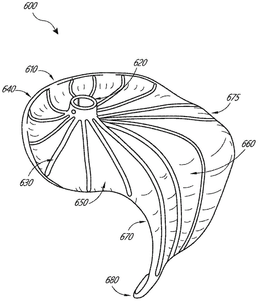
图6图示了对合辅助元件的一个实施方案的立体图。Figure 6 illustrates a perspective view of one embodiment of a docking aid element.
图7A图示了对合辅助元件的一个实施方案的立体图,显示了朝向不良对合的自体瓣叶设置的第一表面。Figure 7A illustrates a perspective view of one embodiment of an coaptation aid element showing a first surface disposed towards a malaligned native leaflet.
图7B图示了图7A的对合辅助元件的另一立体图,显示了可以包括对合表面的第二表面。7B illustrates another perspective view of the mating aid element of FIG. 7A showing a second surface that may include a mating surface.
图7C图示了图7A的对合辅助元件的顶视图。Figure 7C illustrates a top view of the mating assist element of Figure 7A.
图7D图示了植入在二尖瓣的模型内的图7A的对合辅助元件。Figure 7D illustrates the coaptation assist element of Figure 7A implanted within a model of the mitral valve.
图7E图示了植入在二尖瓣的模型内的图7A的对合辅助元件的顶视图。Figure 7E illustrates a top view of the coaptation assist element of Figure 7A implanted within a model of the mitral valve.
图8A示意性地图示了用于经导管技术的递送系统的控制手柄的一个实施方案。Figure 8A schematically illustrates one embodiment of a control handle of a delivery system for transcatheter technology.
图8B示意性地图示了与图8A的递送系统耦接的对合辅助元件的顶视图和侧视图。Figure 8B schematically illustrates top and side views of an abutment assist element coupled with the delivery system of Figure 8A.
图8C示意性地图示了对合辅助元件的环形毂和递送导管的尖端之间的连接。Figure 8C schematically illustrates the connection between the annular hub of the apposition assist element and the tip of the delivery catheter.
图9A示意性地图示了图8A的递送系统的锚固操作。Figure 9A schematically illustrates the anchoring operation of the delivery system of Figure 8A.
图9B-9E示意性地图示了环形锚固件和驱动器之间的连接。9B-9E schematically illustrate the connection between the annular anchor and the driver.
图10示意性地图示了一种用于经导管技术的方法,显示了经隔穿越。Figure 10 schematically illustrates a method for transcatheter technique showing transseptal crossing.
图11示意性地图示了一种用于经导管技术的方法,显示了初始对合辅助元件前进。Figure 11 schematically illustrates a method for the transcatheter technique showing the advancement of the initial coaptation assist element.
图12示意性地图示了一种用于经导管技术的方法,显示了部分对合辅助元件开启。Figure 12 schematically illustrates a method for the transcatheter technique, showing partial apposition assist element opening.
图13示意性地图示了一种用于经导管技术的方法,显示了对合辅助元件塌缩。Figure 13 schematically illustrates a method for the transcatheter technique showing the collapse of the coaptation aid element.
图14示意性地图示了一种用于经导管技术的方法,显示了对合辅助元件的横截面图。Figure 14 schematically illustrates a method for transcatheter techniques, showing a cross-sectional view of an abutment assist element.
图15示意性地图示了一种用于经导管技术的方法,显示了副锚固件放置。Figure 15 schematically illustrates a method for the transcatheter technique showing secondary anchor placement.
图16示出了用于植入物输送的方法,其中显示了植入物的装载;Figure 16 shows a method for implant delivery showing loading of the implant;
图17示出了用于插入引导器的方法;Figure 17 shows a method for inserting an introducer;
图18示出了用于将图17的引导器连接到经隔鞘的方法;Figure 18 shows a method for connecting the introducer of Figure 17 to a transseptal sheath;
图19示出了用于使图18的经隔鞘前进的方法;Figure 19 shows a method for advancing the transseptal sheath of Figure 18;
图20示出了用于定位图18的经隔鞘的方法Figure 20 illustrates a method for positioning the transseptal sheath of Figure 18
图21示出了用于输送锚固件的方法;Figure 21 shows a method for delivering an anchor;
图22A-22D示出了用于部署植入物的方法;22A-22D illustrate a method for deploying an implant;
图23示出了用于使用一个或多个副锚固件导丝的方法;Figure 23 shows a method for using one or more secondary anchor guide wires;
图24示出了用于移除锚固件驱动器的方法;Figure 24 shows a method for removing an anchor driver;
图25示出了用于使副锚固件导轨前进的方法;Figure 25 shows a method for advancing secondary anchor rails;
图26示出了用于输送副锚固件的方法;Figure 26 shows a method for delivering secondary anchors;
图27示出了用于插入副锚固件的方法;Figure 27 shows a method for inserting a secondary anchor;
图28示出了用于输送另一个副锚固件的方法;Figure 28 shows a method for delivering another secondary anchor;
图29示出了被锚固的具有导丝的植入物;Figure 29 shows an anchored implant with a guide wire;
图30示出了被锚固的植入物;Figure 30 shows the anchored implant;
图31A-31F示出了用于取出植入物的方法;31A-31F illustrate a method for removing an implant;
图32示出了用于插入副锚固件的方法;Figure 32 shows a method for inserting a secondary anchor;
图33示出了用于输送另一个副锚固件的方法;Figure 33 shows a method for delivering another secondary anchor;
图34示出了用于插入另一个副锚固件的方法;Figure 34 shows a method for inserting another secondary anchor;
图35示出了被锚固的植入物;Figure 35 shows the anchored implant;
图36示出了层压件的实施例;Figure 36 shows an embodiment of a laminate;
图37示出了层压件的实施例;Figure 37 shows an embodiment of a laminate;
图38示出了3D成形的实施例;Figure 38 shows an embodiment of 3D shaping;
图39示出了3D成形的实施例;Figure 39 shows an embodiment of 3D shaping;
图40示出了植入物;Figure 40 shows the implant;
图41示出了倒钩的实施例;Figure 41 shows an embodiment of a barb;
图42A-42I示出了植入物输送系统的实施例;42A-42I illustrate an embodiment of an implant delivery system;
图43A-43E示出了植入物输送系统的实施例;43A-43E illustrate an embodiment of an implant delivery system;
图44A-44E示出了植入物输送系统的实施例;44A-44E illustrate an embodiment of an implant delivery system;
图45A-45K示出了植入物输送系统的实施例;45A-45K illustrate an embodiment of an implant delivery system;
图46A-46C示出了锚固件输送系统的实施例;46A-46C illustrate an embodiment of an anchor delivery system;
图47A-47E示出了对合辅助元件的实施例的视图;Figures 47A-47E show views of an embodiment of a mating assist element;
图48示出了植入物结构的实施例;Figure 48 shows an embodiment of an implant structure;
图49示出了植入物输送系统的实施例;Figure 49 shows an embodiment of an implant delivery system;
图50示出了输送的方法;Figure 50 shows the method of delivery;
图51示出了主锚固件驱动器的实施例;Figure 51 shows an embodiment of a master anchor driver;
图52示出了副锚固件导轨的实施例;Figure 52 shows an embodiment of a secondary anchor rail;
图53A-53B示出了防止缠结的副锚固件导轨的实施例;Figures 53A-53B illustrate embodiments of secondary anchor rails that prevent tangling;
图54示出了副锚固件导轨的实施例,所述副锚固件导轨用于辅助锚固件的轨迹;Figure 54 shows an embodiment of a secondary anchor rail used to assist in the trajectory of the anchor;
图55A-55C示出了近端组件的实施例;55A-55C illustrate an embodiment of a proximal assembly;
图56示出了防旋转特征的实施例;以及Figure 56 shows an embodiment of an anti-rotation feature; and
图57A-57B示出了后瓣叶增大(augmentation)和恢复的实施例。57A-57B illustrate an embodiment of posterior leaflet augmentation and restoration.
具体实施方式Detailed ways
本发明在一些实施方案中总体上提供通常用于治疗二尖瓣返流和其他瓣膜疾病(包括三尖瓣返流)的改进的医疗装置、系统和方法。尽管以下描述包括对具有两个瓣叶的瓣膜如二尖瓣中的前瓣叶的提及,但是应理解“前瓣叶”可以是指具有多个瓣叶的瓣膜中的一个或多个瓣叶。例如,三尖瓣具有3个瓣叶,因此“前”可以是指内侧瓣叶、外侧瓣叶和后瓣叶中的一个或两个。本文所述的对合辅助元件总体上将包括对合辅助体(在本文中有时称为瓣膜体),当瓣膜的瓣叶在开启的瓣膜构型(前瓣叶与瓣膜体分开)和关闭的瓣膜构型(前瓣叶与相对的瓣膜体表面接合)之间来回移动时,对合辅助体通常沿着血液流动路径。瓣膜体将设置在自体瓣叶之间以通过下列方式封闭由自体瓣叶的不良对合导致的间隙:为自体瓣叶中的至少一个提供用于对合的表面,同时有效地替换瓣膜区域中的第二自体瓣叶,其要是正常工作的话会在收缩期期间闭塞。所述间隙可以是横向的(例如可以由扩张的左心室和/或二尖瓣环引起)和/或轴向的(例如当瓣膜应关闭时一个瓣叶脱垂或被流体压力推出瓣环以外的情形)。在一些实施方案中,对合辅助元件可以完全地辅助一个、两个或更多瓣叶,或在一些实施方案中部分地辅助瓣叶,例如仅覆盖前瓣叶的A1、A2和/或A3扇形区中的一个或多个,和/或后瓣叶的P1、P2和/或P3扇形区中的一个或多个。The present invention generally provides, in some embodiments, improved medical devices, systems and methods generally used for the treatment of mitral regurgitation and other valve diseases, including tricuspid regurgitation. Although the following description includes reference to a valve having two leaflets, such as the anterior leaflet in a mitral valve, it should be understood that "anterior leaflet" may refer to one or more of a valve having multiple leaflets leaf. For example, a tricuspid valve has 3 leaflets, so "anterior" may refer to one or both of the medial, lateral, and posterior leaflets. The coaptation aid elements described herein will generally include coaptation aids (sometimes referred to herein as valve bodies) when the leaflets of the valve are in an open valve configuration (anterior leaflets separated from the valve body) and closed The coaptation aid typically follows the blood flow path as it travels back and forth between valve configurations (anterior leaflet engaging the opposing valve body surface). The valve body will be positioned between the native leaflets to close gaps caused by poor coaptation of the native leaflets by providing at least one of the native leaflets with a surface for coaptation, while effectively replacing in the valve area The second native valve leaflet, which, if functioning properly, would occlude during systole. The gap can be lateral (eg, can be caused by a dilated left ventricle and/or mitral annulus) and/or axial (eg, when the valve should close, one leaflet prolapses or is pushed out of the annulus by fluid pressure) situation). In some embodiments, the coaptation assisting element may assist one, two or more leaflets completely, or in some embodiments partially assist the leaflets, eg, cover only A1, A2, and/or A3 of the anterior leaflet One or more of the sectors, and/or one or more of the P1, P2 and/or P3 sectors of the posterior leaflet.
本文所述的对合辅助元件和方法可以被配置为通过形成在其内天然二尖瓣叶中的至少一个可以密封的人工或新的对合区来治疗功能性和/或退行性二尖瓣返流(MR),也可被用于其他用途。本文中的结构和方法将在很大程度上裁制成适合于此应用,尽管备选实施方案可以被配置用于心脏和/或身体的其它瓣膜,包括三尖瓣、外周血管系统、下腔静脉等的瓣膜。The coaptation aid elements and methods described herein can be configured to treat a functional and/or degenerative mitral valve by forming at least one prosthetic or new coaptation zone within which at least one of the native mitral valve leaflets can be sealed Reflux (MR) can also be used for other purposes. The structures and methods herein will be largely tailored to this application, although alternative embodiments may be configured for use with other valves of the heart and/or body, including the tricuspid valve, peripheral vasculature, inferior lumen Valves of veins etc.
参见图1A-1D,心脏的四个腔室被示出,左心房10、右心房20、左心室30、和右心室40。二尖瓣60设置在左心房10和左心室30之间。还示出了三尖瓣50(其将右心房20和右心室40分开)、主动脉瓣80和肺动脉瓣70。二尖瓣60由两个瓣叶(前瓣叶12和后瓣叶14)组成。在健康的心脏中,两个瓣叶在收缩期期间在对合区16处并置(appose)。Referring to FIGS. 1A-1D , four chambers of the heart are shown, left
作为心脏架的一部分的纤维瓣环120为被称为前瓣叶12和后瓣叶14的二尖瓣的两个瓣叶提供附接。瓣叶通过附接至腱索32而被轴向支撑。所述腱索又附接至左心室的乳头肌34、36中的一个或两者。在健康的心脏中,所述腱索支持结构拴系二尖瓣瓣叶,允许瓣叶在舒张期期间容易地打开,但是耐受心室收缩期期间产生的高压。除了支持结构的拴系作用以外,瓣叶的形状和组织一致性有助于促进有效密封或对合。前瓣叶和后瓣叶的前沿沿漏斗形(funnel-shaped)的对合区16会合,其中三维对合区(CZ)的侧向横截面160示意性地显示在图1E中。The
二尖瓣前瓣叶和二尖瓣后瓣叶具有不同的形状。前瓣叶更牢固地附接于覆盖中心纤维体(心脏架)的瓣环,并且比后瓣叶稍硬,所述后瓣叶附接于移动性更大的后二尖瓣环(posterior mitral annulus)。约80%的闭合区域是前瓣叶。邻近连合(commissure)110、114、在瓣环120之上或之前,存在有左(外侧(lateral))纤维三棱124和右(间隔(septal))纤维三棱126,所述左、右纤维三棱形成于二尖瓣环与主动脉的非冠状尖(non-coronarycusp of the aorta)的基部融合处(图1F)。纤维三棱124、126形成中心纤维体128的间隔延伸和外侧延伸(septal and lateral extents)。在一些实施方案中,纤维三棱124、126可以具有优点,如提供牢固的区域,所述牢固区域用于与一个或多个环形锚固件(archor)或心房锚固件的稳定接合。瓣叶12、14之间的对合区CL不是一条简单的线,而是弯曲的漏斗形的表面界面。第一连合110(外侧或左侧的)和第二连合114(间隔或右侧的)是前瓣叶12在瓣环120处与后瓣叶14相会的地方。如在图1C、1D和1F的心房的轴向视图中最清楚可见的,对合区的轴向横截面通常显示弯曲的线CL,所述线CL与瓣环的形心CA分开,并且在舒张期CO期间与通过瓣膜的开口分开。此外,瓣叶边缘具有圆齿(scalloped),相比于前瓣叶,后瓣叶更是如此。不良对合可能发生在这些A-P(前-后)区段对A1/P1、A2/P2和A3/P3中的一个或多个之间,使得不良对合特性可能沿对合区CL的曲线而变化。The anterior and posterior mitral valve leaflets have different shapes. The anterior leaflets are more firmly attached to the annulus covering the central fibrous body (heart frame) and are slightly stiffer than the posterior leaflets, which are attached to the more mobile posterior mitral annulus annulus). About 80% of the closed area is the anterior leaflet. Adjacent to the
现在参看图2A,正确发挥功能的心脏二尖瓣60在舒张期期间是打开的以允许血液沿从左心房向左心室30的流动路径FP流动并且由此充填左心室。如在图2B中所示,先是被动地然后是主动地通过心室压力升高,发挥功能的二尖瓣60在收缩期期间闭合并且有效地将左心室30和左心房10分隔开,由此允许左心室周围的心脏组织收缩从而推动血液通过血管系统。Referring now to Figure 2A, a properly functioning cardiac
参见图3A-3B和4A-4B,存在若干病症或疾病状态,其中二尖瓣的瓣叶边缘不能充分对置并且由此允许血液在收缩期中从心室涌回到心房中。不管特定患者的具体病因(etiology)如何,瓣叶在心室收缩期期间不能密封被称为不良对合并且造成二尖瓣返流。Referring to Figures 3A-3B and 4A-4B, there are several disorders or disease states in which the leaflet edges of the mitral valve do not sufficiently oppose and thereby allow blood to rush from the ventricle back into the atrium during systole. Regardless of the specific etiology of a particular patient, the failure of the valve leaflets to seal during ventricular systole is referred to as malapposition and causes mitral regurgitation.
通常,不良对合可以由一个或两个瓣叶的支持结构的过度拴系造成,或可以由支持结构的过度拉伸或撕裂造成。其他较不常见的原因包括心瓣膜感染、先天性异常、以及创伤。瓣膜机能不良可以由以下引起:腱索被拉伸(被称为二尖瓣脱垂),以及在一些情况中腱索215或乳头肌的撕裂(被称为连枷瓣叶220),如在图3A中所示。或者,如果瓣叶组织自身是多余的,则瓣膜可能脱垂以致对合的高度发生在进入心房中更高的位置,在心室收缩期230期间在心房中更高的位置开启瓣膜。瓣叶中的任一个可能发生脱垂或变成连枷。此病症有时被称为退行性二尖瓣返流。Often, poor coaptation can result from excessive tethering of the support structures of one or both leaflets, or can result from excessive stretching or tearing of the support structures. Other less common causes include heart valve infections, congenital abnormalities, and trauma. Valve dysfunction can be caused by stretching of the chordae tendineae (known as mitral valve prolapse), and in some cases tearing of the
在如图3B中所示的过度拴系中,结构正常的瓣膜的瓣叶可能由于瓣环增大或形状改变(所谓的瓣环扩大240)而不能适当地发挥功能。此种功能性二尖瓣返流通常由心肌衰竭和伴发性心室扩大引起。并且由功能性二尖瓣返流引起的过大的容量负荷自身可能加重心力衰竭、心室和瓣环扩大,并且由此使二尖瓣返流恶化。In hypertethering as shown in Figure 3B, the leaflets of a structurally normal valve may not function properly due to annulus enlargement or change in shape (so-called annulus enlargement 240). This functional mitral regurgitation is usually caused by myocardial failure and concomitant ventricular enlargement. And the excessive volume overload caused by functional mitral regurgitation may itself exacerbate heart failure, ventricular and annular enlargement, and thus worsen mitral regurgitation.
图4A-4B图示了在收缩期期间在功能性二尖瓣返流(图4A)和退行性二尖瓣返流(图4B)中血液的回流BF。图4A中瓣环的增加的尺寸,加上由于心室320和乳头肌330的肥大所致的增加的拴系,阻止前瓣叶312和后瓣叶314并置,由此阻止对合。在图4B中,腱索215的撕裂导致后瓣叶344向上脱垂到左心房中,这阻止了与前瓣叶342的并置。在任一种情况中,结果都是血液回流到心房中,这降低左心室压缩的有效性。4A-4B illustrate the regurgitation BF of blood in functional mitral regurgitation (FIG. 4A) and degenerative mitral regurgitation (FIG. 4B) during systole. The increased size of the annulus in Figure 4A, coupled with increased tethering due to hypertrophy of
可以与本文公开内容结合利用的对合辅助元件、工具、锚固件、特征、系统和方法的另外描述可以在以下申请中找到,其中的每个都以其整体通过引用并入:美国专利申请号13/099532,2011年5月3日提交;美国专利申请号13/531407,2012年6月22日提交;美国专利申请号14/313975,2014年6月24日提交;美国专利申请号14/742199,2015年6月17日提交;美国专利申请号14/749344,2015年6月24日提交;和美国专利申请号10/419706,2003年4月18日提交。Additional descriptions of involution aids, tools, anchors, features, systems and methods that may be utilized in conjunction with the present disclosure can be found in the following applications, each of which is incorporated by reference in its entirety: US Patent Application No. 13/099532, filed May 3, 2011; US Patent Application No. 13/531407, filed June 22, 2012; US Patent Application No. 14/313975, filed June 24, 2014; US Patent Application No. 14/ 742199, filed June 17, 2015; US Patent Application No. 14/749344, filed June 24, 2015; and US Patent Application No. 10/419706, filed April 18, 2003.
在一些实施方案中,本文所述的对合辅助元件可以被部署为覆盖后瓣叶、腱索和乳头肌。在一些实施方案中,对合辅助元件经由环形锚固件和/或心室锚固件在上方附接至瓣环的后方和在下方附接至左心室的后方。在其他实施方案中,可以使用多于一个环形锚固件和/或多于一个心室锚固件来附接对合辅助元件。在一些装置中,一个或多个环形锚固件可以被一个或多个心房或连合锚固件替代或者补充有一个或多个心房或连合锚固件,其在一些实施方案中可以是环形的。对合辅助元件可以附接至后瓣环的上表面、后心房壁或瓣环本身。已经在对合辅助元件和天然前瓣叶之间建立对合区。类似的对合辅助元件可以用于功能性和退行性二尖瓣返流两者,因为无论功能障碍背后的机制如何,在两者中都发生瓣叶对合的失效。在一些实施方案中,可以将不同尺寸的对合辅助元件放置为使得天然前瓣叶与对合元件在适当建立的对合点处相对,阻挡在心室收缩期间的血液流动。In some embodiments, the coaptation aid elements described herein can be deployed to cover the posterior leaflets, chordae tendineae, and papillary muscles. In some embodiments, the coaptation assist element is attached superiorly to the posterior of the annulus and inferiorly to the posterior of the left ventricle via annular anchors and/or ventricular anchors. In other embodiments, more than one annular anchor and/or more than one ventricular anchor may be used to attach the coaptation assist element. In some devices, one or more annular anchors may be replaced by or supplemented with one or more atrial or commissural anchors, which in some embodiments may be annular. The coaptation aid element may be attached to the superior surface of the posterior annulus, the posterior atrial wall, or the annulus itself. A coaptation zone has been established between the coaptation aid element and the native anterior leaflet. Similar coaptation aid elements can be used for both functional and degenerative mitral regurgitation, as failure of leaflet coaptation occurs in both regardless of the mechanism behind the dysfunction. In some embodiments, different sized coaptation assist elements may be placed such that the native anterior leaflet opposes the coaptation element at a properly established coaptation point, blocking blood flow during ventricular systole.
通过使配置用于多种解剖学的尺寸不同,可以提供对合辅助元件的多种尺寸。例如,可以存在在基本垂直于由瓣膜的瓣环限定的平面的平面中从对合辅助元件的上瓣环附接部位到最下边缘测量的高度,对合点和上附接部位之间的深度,和在对合点高度的后壁和对合点之间的凸出。也存在对合辅助元件的内外直径,典型地在功能MR中较大。在舒张期期间,对合辅助元件可以停留在基本上相同的位置,同时天然前瓣叶的移动开启瓣膜,允许血液以最小的限制从左心房流动到左心室。在一些实施方案中,对合辅助元件的表面可以在心室收缩期期间向上成气球状或拉伸,同时锚固件保持不动。这可以是有利的,因为增强在收缩期期间在对合区处的装置的前或对合表面和自体瓣叶之间的密封。在舒张期期间,表面可以朝前瓣叶返回其中其更早先所处的初始位置。这可以在舒张期期间提供改善的在心房和心室之间的血液流动路径,从而改善经过对合辅助元件从心房的流出。By having different sizes configured for a variety of anatomies, a variety of sizes of the apposition aid element can be provided. For example, there may be a height measured in a plane substantially perpendicular to the plane defined by the annulus of the valve from the upper annulus attachment site of the coaptation aid element to the lowermost edge, the depth between the coaptation point and the upper attachment site , and the bulge between the rear wall at the height of the apposition and the apposition. There are also inner and outer diameters of the involution assist element, which are typically larger in functional MR. During diastole, the coaptation assist element can stay in substantially the same position while movement of the native anterior leaflet opens the valve, allowing blood to flow from the left atrium to the left ventricle with minimal restriction. In some embodiments, the surface of the apposition assist element can be ballooned or stretched upward during ventricular systole while the anchor remains stationary. This may be advantageous as the seal between the anterior or coaptation surface of the device and the native leaflets at the coaptation zone is enhanced during systole. During diastole, the surface may return towards the anterior leaflet to the initial position where it was earlier. This may provide an improved blood flow path between the atrium and the ventricle during diastole, thereby improving outflow from the atrium through the coaptation assist element.
在一些使用方法中,天然后瓣叶留在原位,并且对合辅助元件在上方附接至后瓣环或相邻的心房壁。多种可能的备选实施方案可以具有不同的附接机制。在其他使用方法中,后瓣叶不存在,已经手术移除或由于疾病移除。在一些使用方法中,自体瓣叶附接至对合辅助元件的后表面。在一些使用方法中,对合辅助元件可以附接至后瓣叶的前表面,而不是瓣环或心房壁。这些是变化方案的一些实例,但是仍然考虑其他方案。在一些使用方法中,锚固结构(未示出)可以从对合辅助元件开始穿过心房壁进入到冠状窦中,其中锚固结构附接至冠状窦中的配合结构。在一些使用方法中,可以是机械结构或简单缝合的锚固结构可以穿过心房壁并且通过结或机械单元如夹子锚固在心脏的心外膜表面上。类似地,下方的附接可以到达心室肌,通过心尖进入到心外膜或心包,并且使用备选附接单元从外侧或在其他附接部位处紧固。In some methods of use, the posterior valve leaflets are left in place and the coaptation assist element is attached superiorly to the posterior annulus or adjacent atrial wall. Various possible alternative embodiments may have different attachment mechanisms. In other methods of use, the posterior leaflets are absent, have been removed surgically or due to disease. In some methods of use, the native leaflets are attached to the posterior surface of the coaptation aid element. In some methods of use, the coaptation aid element may be attached to the anterior surface of the posterior leaflet, rather than the annulus or atrial wall. These are some examples of variations, but others are still contemplated. In some methods of use, an anchoring structure (not shown) may pass from the coaptation assist element through the atrial wall into the coronary sinus, where the anchoring structure is attached to a mating structure in the coronary sinus. In some methods of use, the anchoring structure, which may be a mechanical structure or a simple suture, may pass through the atrial wall and be anchored to the epicardial surface of the heart by a knot or mechanical unit such as a clip. Similarly, the inferior attachment can reach the ventricular myocardium, through the apex into the epicardium or pericardium, and secure from the outside or at other attachment sites using alternative attachment units.
本文所述的对合辅助元件可以表现出多种所需特性。一些实施方案不必依赖于二尖瓣环的整形(如通过瓣环组织的热收缩、瓣环环假体的植入和/或抓牢机构在瓣膜平面上方或下方或者在冠状窦或相关血管中的放置)。有利地,它们也不必破坏瓣叶结构或依赖于二尖瓣叶的一起锁定或融合。多个实施方案可以避免对心室整形的依赖性,并且在植入后表现出具有有限偏移的被动型植入装置,这可以产生非常长的疲劳寿命。因此,对合辅助元件可以穿过后瓣叶紧固,而在其他方面使天然心脏(例如,心室的、二尖瓣环等)解剖学完整。The involution aids described herein can exhibit a variety of desirable properties. Some embodiments do not necessarily rely on reshaping of the mitral annulus (eg, by thermal shrinkage of annular tissue, implantation of annulus prostheses and/or grasping mechanisms above or below the plane of the valve or in the coronary sinus or associated vessels). placement). Advantageously, they also do not have to destroy the leaflet structure or rely on locking or fusion of the mitral leaflets together. Embodiments can avoid reliance on ventricular remodeling and exhibit passive implant devices with limited excursion after implantation, which can result in very long fatigue life. Thus, the coaptation aid element can be secured through the posterior leaflets, while otherwise anatomically intact to the native heart (eg, ventricular, mitral annulus, etc.).
无论哪个或哪些瓣叶部分表现出不良对合,二尖瓣不良对合的缓解都可以是有效的。本文所述的处理将利用在过程期间可重新布置并且甚至在完全部署和/或组织响应开始或完成后可移除的对合辅助元件,通常不损坏瓣膜结构。尽管如此,本文所述的对合辅助元件可以与确实依赖于上述被排除的属性中的一个或多个的一种或多种疗法组合。对合辅助元件可以表现出良性组织愈合和快速内皮化,其抑制迁移、血栓栓塞、感染和/或糜烂。在一些情况下,对合辅助元件将不表现出内皮化,但是其表面将保持惰性,这也可以抑制迁移、血栓栓塞、感染和/或糜烂。Relief of malapposition of the mitral valve can be effective regardless of which leaflet part or parts exhibit the malapposition. The treatments described herein will utilize an apposition assist element that is repositionable during the procedure and even removable after full deployment and/or tissue response is initiated or completed, generally without damaging the valve structure. Nonetheless, the apposition aids described herein can be combined with one or more therapies that do rely on one or more of the above-mentioned excluded attributes. The apposition assist element may exhibit benign tissue healing and rapid endothelialization, which inhibits migration, thromboembolism, infection and/or erosion. In some cases, the apposition assist element will not exhibit endothelialization, but its surface will remain inert, which may also inhibit migration, thromboembolism, infection and/or erosion.
图5A-5B示出对合辅助元件500的一个实施方案的两个视图。对合辅助元件500可以包括朝不良对合自体瓣叶(在二尖瓣的情形中,后瓣叶)设置的第一表面505,和可以朝前瓣叶设置的第二表面515。第二表面515可以包括对合表面560。对合辅助元件500的上边缘540可以弯曲以配合瓣环或相邻心房壁的总体形状,如本文所述。上边缘540可以朝后瓣叶向下弯曲,如图5A中所示,或者朝心房壁向上弯曲以配合左心房壁的总体形状,如图6中所示和本文所述。5A-5B illustrate two views of one embodiment of a
对合辅助元件500可以具有允许其在心房和心室中的附接部位之间横切瓣膜的几何结构。在一些实施方案中,附接部位仅在心房中。在一些实施方案中,附接部位仅在瓣膜的瓣环和连合附近。对合辅助元件500可以在下边缘580附近不附接。对合辅助元件500不需要心室附接。在一些实施方案中,对合辅助元件500的几何结构有助于保持对合辅助元件500在瓣膜内的位置。在一些实施方案中,对合辅助元件500弯曲以使后瓣叶成杯状。在一些实施方案中,对合辅助元件500朝上边缘540向后弯曲。对合辅助元件500可以提供对合表面560用于对合前瓣叶。图5A和5B图示了该几何结构。Coaptation assist
在一些使用方法中,后瓣叶可以保持完整。对合辅助元件500可以附接至心房或瓣环以使得其有效地封闭后瓣叶。在一些使用方法中,可以移除后瓣叶。在移除或已经移除了后瓣叶的情形中,对合辅助元件500可以代替后瓣叶。在一些实施方案中,对合辅助元件500仅需要瓣环附接。在一些实施方案中,对合辅助元件500仅需要在单点处的附接。该单点可以是对合辅助元件500的中央位置,例如,位于中央的毂。在一些实施方案中,对合辅助元件500可以沿边缘附接至心房或瓣环。在一些实施方案中,对合辅助元件500可以在与对合辅助元件500的边缘隔开的位置处,例如,在位于中央的毂处附接至心房或瓣环。In some methods of use, the posterior leaflets may remain intact. Coaptation assist
对合辅助元件500可以包括接合环形锚固件800的环形毂520。环形锚固件800可以在近端通过本文所述的驱动器接合。环形锚固件800可以包括锋利尖端以接合组织。在一些使用方法中,环形锚固件800的尖端在递送对合辅助元件500期间在环形毂520内。在一些使用方法中,环形锚固件800的尖端在递送期间在环形部分510上方。环形锚固件800的尖端可以保持凹在环形毂520内直到旋转环形锚固件800以接合组织。在一些实施方案中,对合辅助元件500可以体外组装,将环形锚固件800经由环形毂520与对合辅助元件500接合并将驱动器与环形锚固件800接合。然后驱动器可以缩回到递送导管中,其中对合辅助元件500处于塌缩位置。驱动器可以由操作人员单独地操纵以将环形锚固件800放置在适当位置中。备选地,在通过递送导管部署之前或之后,可以将环形锚固件800依次与对合辅助元件500和/或驱动器接合。在放置后的对合辅助元件500可以完整地覆盖后瓣叶以使得对合辅助元件500在收缩期期间与前瓣叶对合,并且与天然前瓣叶一起保持在瓣环环处的瓣膜密封。The
在一些实施方案中,环形锚固件800是主动型锚固件。使用者可以选择性地将环形锚固件800与组织接合或脱离。与倒钩或其他被动型锚固件不同,主动型锚固件800可以例如通过旋转来激活以接合组织。环形锚固件800允许在环形锚固件800的接合之前放置对合辅助元件500。对合辅助元件500可以在没有环形锚固件800的任何附着的情况下与组织接触。在一些实施方案中,环形锚固件800和相应的毂520中央地位于对合辅助元件500上。环形锚固件800和相应的毂520与对合辅助元件500的任何边缘间隔开。环形锚固件800和相应的毂520的位置可以在中间的中心,以防止在用环形毂520支撑对合辅助元件500时对合辅助元件500的摇摆。相应的毂520提供一个方便的位置以支撑和移动对合辅助元件500。In some embodiments,
环形毂520可以具有内置或耦接的环形锚固件800。在一些实施方案中,环形锚固件800可以通过本文所述的横穿销保持在环形毂520内。横穿销可以穿过环形锚固件800的螺旋结构以防止环形锚固件800通过钝力从环形毂520移出。环形锚固件800可以包括相对于环形毂520可旋转的螺旋结构。在一些实施方案中,可以使用其他锚固件。环形锚固件800可以是从对合辅助元件500经过心室间隔延伸到右心室的绳索或其他附接单元的形式。环形锚固件800可以是经过心尖延伸到心外膜或心包中的绳索或其他附接单元的形式。环形锚固件800可以在组合的心外膜/心内膜过程(combined endo/epiprocedure)中从心脏外部紧固。当使用螺旋锚固件时,它们可以包含生物惰性材料,如铂/lr、镍钛诺和/或不锈钢。The
在一些实施方案中,对合辅助元件500可以包括在环形毂520内部的单个中央环形锚固件800。对合辅助元件500可以如本文所述通过递送导管与环形毂520的附接经皮递送。对合辅助元件500可以被配置为通过将环形锚固件800移除和再附接而可调整地布置。对合辅助元件500可以通过环形锚固件800的移除和对合辅助元件500的收回而可再捕获。对合辅助元件500还可以包括副锚固件,其包括连合锚固件、心室锚固件、环形锚固件、倒钩、绳索或任何其他已知固定装置。In some embodiments, the abutment assist
如图5A-5B中可以看到的,对合辅助元件500可以包括多个支柱530。在一些实施方案中,支柱530中的一个或多个具有在毂520处终止的一个端部和朝对合辅助元件500的上边缘540、侧向边缘570和575以及下边缘580中的一个向外径向延伸的另一端部。支柱530可以从毂520沿各种方向向外延伸,并且可以以规律或不规律的间隔与相邻支柱530间隔开。在一些实施方案中,相邻的支柱530以相对于相邻支柱530约5度至约45度、约10度至约30度或约5、10、15、20、25或30度的角度从毂向外延伸。支柱530可以大体平行于对合辅助元件500的纵轴布置以帮助在放置时保持对合辅助元件500形状。支柱530可以使对合辅助元件500采取用于通过导管部署的减小构型。在一些实施方案中,形成植入物500的对合区的一部分的支柱530具有比仅形成植入物的环形区的一部分的支柱530大的最大长度。在一些实施方案中,形成植入物的对合区的一部分的支柱530可以例如比形成植入物的环形区的一部分的支柱530长至少约10%、20%、30%、40%、50%、75%、100%、125%或150%。As can be seen in FIGS. 5A-5B , the
图5A示出具有瓣环锚固部位535的对合辅助元件500的视图。瓣环锚固部位535可以是支柱530的一部分。瓣环锚固部位535在图5A中显示为从对合辅助元件500向下延伸。在其他实施方案中,瓣环锚固部位535可以从对合辅助元件500沿其他方向延伸以接合组织。在一些实施方案中,瓣环锚固部位535包括具有锋利尖端的一个或多个倒钩。瓣环锚固部位535可以是被动型锚固件。FIG. 5A shows a view of an
在一些实施方案中,对合辅助元件500可以包括一个或多个可缩回倒钩。例如,可以在对合辅助元件500的递送期间使倒钩缩回。例如,可以在相对于解剖结构布置对合辅助元件500后使倒钩前进。在一些实施方案中,使倒钩主动地缩回和/或前进。例如,本文所述的递送导管可以包括被设计为使倒钩缩回和/或前进的与倒钩耦接的机构。在其他实施方案中,使倒钩被动地前进和/或缩回。在一些实施方案中,在倒钩处于缩回状态的情况下递送对合辅助元件500。在一些实施方案中,倒钩可以被如本文所述的瓣膜体覆盖物覆盖。在一些实施方案中,组织和瓣膜体覆盖物之间的界面将瓣膜体覆盖物推回并且使倒钩暴露。在一些实施方案中,组织溶解和/或吸收瓣膜体覆盖物的一部分并且使倒钩暴露。在一些实施方案中,本文所述的钱袋口抽合绳型缝线的移动使倒钩前进。在一些实施方案中,钱袋口抽合绳型缝线的移动造成造成瓣膜体覆盖物的移动以使倒钩暴露。可以考虑其他构型。In some embodiments, the
瓣环锚固部位535可以限定图5B中所示的直径D1,其在一些实施方案中可以对应于天然瓣膜的内和外连合之间的距离或连合内距离(ICD)。D1可以是20-60mm,在一些实施方案中,优选长度为35-45mm,其最接近地对应于人二尖瓣ICD的最宽范围。在一些实施方案中,D1可以是从右纤维三角到左纤维三角的距离。The
对合辅助元件500可以包括大体环形部分510。当部署对合辅助元件500时,环形部分510可以布置在自体瓣叶上方。在一些实施方案中,环形部分510可以朝瓣环弯曲或远离瓣环弯曲。环形部分510可以是凹形。在其他实施方案中,环形部分510可以相对于瓣环基本上是平的。支柱530中的一个或多个可以从毂520朝上边缘540侧向弯曲以帮助在部署时保持对合辅助元件500的环形部分510的形状。对合辅助元件500可以从毂520朝瓣环锚固部位535向下弯曲。在一些实施方案中,对合辅助元件500不靠向后瓣叶。在一些实施方案中,瓣环锚固部位535是二尖瓣的后瓣环和对合辅助元件500之间的仅有的接触点。上边缘540可以包括环形曲率半径。环形曲率半径可以朝瓣环弯曲。环形曲率半径可以朝对合表面560弯曲。在一些实施方案中,环形曲率半径可以是0mm-5mm、5mm-10mm、10mm-15mm、15mm-20mm、20mm-25mm、25mm-30mm等。The
支柱530可以由不透射线的材料构成。在一些实施方案中,支柱530由可弹性形变的材料如形状记忆金属例如镍钛诺或形状记忆聚合物构成。在一些实施方案中,所述材料是EIgiloy。在其他实施方案中,支柱530可以由其他材料构成,包括不锈钢、聚丙烯、高密度聚乙烯(PE)、涤纶、无细胞胶原基质如SIS、或其他塑料等。在其他实施方案中,支柱530可以是组合,如围绕ePTFE、涤纶和/或聚丙烯的芯的高密度PE鞘。支柱530可以具有圆形横截面、卵形横截面,或是带状。在一些实施方案中,支柱530是螺旋弹簧或之字形形状。支柱530可以具有恒定的刚度。在一些实施方案中,一个或多个支柱530沿所述一个或多个支柱530的长度可以具有不同的刚度。支柱530可以在瓣环端部比在对合辅助元件500的心室端部硬。支柱530可以在瓣环端部比在对合辅助元件500的心室端部较不硬。支柱530可以在中点处,例如在拐点或曲线处较硬。支柱530连同一个或多个其他支撑结构可以形成框架。在一些实施方案中,可以提供平行于对合辅助元件500的上边缘540延伸并且帮助保持上边缘540的形状的一个或多个支撑结构。在一些实施方案中,支柱530和/或框架的其他支撑结构可以从镍钛诺管激光切割。The
对合辅助元件体覆盖物550可以由诸如ePTFE的材料构成。用于对合辅助元件体覆盖物550的其他材料包括聚酯、聚氯酯泡沫、聚碳酸酯泡沫、生物组织(如猪心包、加工的牛心包、胸膜、腹膜)、有机硅、涤纶、非细胞胶原基质等。在一些实施方案中,对合辅助元件体覆盖物550可以包括被ePTFE包围的泡沫材料。海绵或泡沫材料的使用增强使对合辅助元件500折叠至足够小的直径以穿过导管的能力。在一些实施方案中,对合辅助元件体覆盖物550没有孔。在其他实施方案中,对合辅助元件体覆盖物550可以具有微孔以增强内皮化和细胞附接。对合辅助元件体覆盖物550也可以包含不透射线的材料或用于较好可视化的回声增强材料。包括支柱530或包括毂520的支撑界面的对合辅助元件500的任何支撑结构可以用不透射线的材料如金或铂涂覆,或者用钡浸渍。对合表面560可以用回声增强材料涂覆。对合辅助元件体覆盖物550可以用抑制血栓形成的材料如肝素键合化合物或喹啉和喹喔啉化合物,或者用加速内皮化的材料,或者用抑制感染的抗生素涂覆。在一些实施方案中,本文所述的钱袋口抽合绳型缝线1010可以包含不透射线的材料或用于较好可视化的回声增强材料。The mating
在一些实施方案中,支柱530可以夹在对合辅助元件体覆盖物550的层之间。对合辅助元件体覆盖物550在第一表面505和第二表面515上可以由相同材料构成。对合辅助元件体覆盖物550在第一表面505或其一部分和第二表面515或其一部分上可以由不同材料构成。在一些实施方案中,支柱530可以附接至或嵌入对合辅助元件体覆盖物550的单层的第一表面505或第二表面515。在一些实施方案中,支柱530可以通过对合辅助元件体覆盖物550“缝合”。瓣环锚固部位535可以是支柱530从对合辅助元件体覆盖物550的暴露端部。In some embodiments, the
对合辅助元件500可以包括钱袋口抽合绳型缝线1010。钱袋口抽合绳型缝线1010可以沿对合辅助元件500的一部分延伸。钱袋口抽合绳型缝线1010可以沿上边缘540或其一部分延伸。钱袋口抽合绳型缝线1010可以沿侧向边缘570或其一部分延伸。钱袋口抽合绳型缝线1010可以沿侧向边缘575或其一部分延伸。钱袋口抽合绳型缝线1010可以沿下边缘580或其一部分延伸。钱袋口抽合绳型缝线1010可以沿对合辅助元件500的周长或其一部分延伸。钱袋口抽合绳型缝线1010可以沿一个或多个支柱530延伸。钱袋口抽合绳型缝线1010可以以直线路径、非直线路径、曲线、半圆或任何开放或闭合形状延伸。The
在一些实施方案中,钱袋口抽合绳型缝线1010可以夹在瓣膜体覆盖物550的层之间。例如,钱袋口抽合绳型缝线1010可以设置在对合辅助元件体覆盖物550的层之间的腔中。在一些实施方案中,钱袋口抽合绳型缝线1010可以附接至或嵌入瓣膜体覆盖物550的单层的第一表面505或第二表面515。在一些实施方案中,钱袋口抽合绳型缝线1010可以穿过对合辅助元件体覆盖物550“缝纫”。钱袋口抽合绳型缝线1010可以穿过第一表面505到第二表面515并回到第一表面505。钱袋口抽合绳型缝线1010可以包括从对合辅助元件体覆盖物550的一个或多个暴露端部。在钱袋口抽合绳型缝线1010是环状物的实施方案中,钱袋口抽合绳型缝线可以包括环状物从瓣膜体覆盖物的一个或多个暴露部分。In some embodiments, the
对合辅助元件500可以通过拉紧钱袋口抽合绳型缝线1010来塌缩。对合辅助元件500可以通过放松钱袋口抽合绳型缝线1010来展开。一个或多个暴露端部或环状物可以通过递送导管或其他工具操纵以拉紧或放松钱袋口抽合绳型缝线1010。塌缩或展开对合辅助元件500的能力可以有利于对合辅助元件500的再捕获和/或对合辅助元件500的重新布置。The
对合辅助元件500可以通过拉紧一个或多个钱袋口抽合绳型缝线1010和/或放松一个或多个钱袋口抽合绳型缝线1010来旋转。例如,拉紧在侧向边缘570上的一个或多个钱袋口抽合绳型缝线1010和/或放松在侧向边缘575上的一个或多个钱袋口抽合绳型缝线1010可以使对合辅助元件500旋转。一个或多个钱袋口抽合绳型缝线1010可以耦接至对合辅助元件500以实现多方向旋转。The
对合辅助元件500可以通过放松钱袋口抽合绳型缝线1010来展开。一个或多个暴露端部或环状物可以通过递送导管或其他工具操纵以拉紧或放松钱袋口抽合绳型缝线1010。塌缩或展开对合辅助元件500的能力可以有利于对合辅助元件500的再捕获和/或对合辅助元件500的重新布置。The
对合辅助元件500的对合表面560可以通过钱袋口抽合绳型缝线1010的移动来调整。一个或多个暴露端部或环状物可以通过递送导管或其他工具操纵以拉紧或放松钱袋口抽合绳型缝线1010从而原位地改变对合表面560的曲率。调整对合辅助元件500的曲率的能力可以有利于符合包括前瓣叶的几何结构的心脏的几何结构。The
对合辅助元件500的环形尺寸可以通过钱袋口抽合绳型缝线1010的移动来调整。一个或多个暴露端部或环状物可以通过递送导管或其他工具操纵以拉紧或放松钱袋口抽合绳型缝线1010从而原位地改变对合辅助元件500的一个或多个尺寸。调整对合辅助元件500的尺寸的能力可以有利于符合心脏的几何结构。The annular size of the mating assist
对合辅助元件500可以包括一个或多个钱袋口抽合绳型缝线1010。在一些实施方案中,对合辅助元件500包括一个钱袋口抽合绳型缝线、两个钱袋口抽合绳型缝线、三个钱袋口抽合绳型缝线、四个钱袋口抽合绳型缝线、五个钱袋口抽合绳型缝线、六个钱袋口抽合绳型缝线、七个钱袋口抽合绳型缝线、八个钱袋口抽合绳型缝线、九个钱袋口抽合绳型缝线、十个钱袋口抽合绳型缝线等。例如,钱袋口抽合绳型缝线1010可以沿对合辅助元件500的各边缘延伸。当提供多个钱袋口抽合绳型缝线时,钱袋口抽合绳型缝线1010可以一起用于改变对合辅助元件500的构型。当提供多个钱袋口抽合绳型缝线时,钱袋口抽合绳型缝线1010可以独立地用于改变对合辅助元件500的构型。The
图5A进一步图示了对合元件高度,其对应于垂直于由瓣膜的瓣环限定的平面测量的下边缘580和环形毂520之间的距离。一些实施方案的对合元件高度可以是10-80mm,而一些实施方案是40-55mm。对合元件高度可以是10-20mm、20-30mm、30-40mm、40-50mm、50-60mm、60-70mm、70-80mm等。Figure 5A further illustrates the apposition element height, which corresponds to the distance between the
图5A图示了对合辅助元件500的大体三角形形状,使得对合辅助元件500具有上边缘540、侧向边缘570和575以及下边缘580。FIG. 5A illustrates the generally triangular shape of the
在一些实施方案中,上边缘540具有大于下边缘580的长度的长度,使得侧向边缘570和575之间的横向距离大体从对合辅助元件500上的上部到下部减小。例如,上边缘540的长度可以在15-50mm或25-35mm的范围内,而下边缘580的长度可以在1-15mm或2-6mm的范围内。In some embodiments, the
环形毂520可以是毂、孔眼或本领域中已知的任何其他拴系部位。在一些实施方案中,环形毂520位于距离D1的中点处。在一些实施方案中,环形毂520位于中间的中心处以防止在通过环形毂520支撑对合辅助元件500时对合辅助元件500的摇摆。在其他实施方案中,环形毂520位于连合中的一个处。尽管仅示出一个环形锚固件800,但是在其他实施方案中,可以提供两个以上环形毂520。The
在一些实施方案中,支柱530可以包括NiTi管。在一些实施方案中,支柱530可以从所述管激光切割。在一些实施方案中,包括一个或多个支柱530和/或一个或多个支撑结构的框架可以从单片材料激光切割。在一些实施方案中,包括一个或多个支柱530、环形毂520和/或一个或多个支撑结构的框架可以整体形成。在一些实施方案中,对合辅助元件体覆盖物550包括ePTFE层压体。所述层压体可以包围支柱530中的一个或多个和/或一个或多个支撑结构(例如,一侧、两侧、第一侧505、第二侧515)。支柱530和/或一个或多个支撑结构可以被两个以上层压层围住。对合辅助元件500的环形部分510的周边可以成向下的杯状。对合辅助元件500的环形部分510的周边可以成向上的杯状。对合辅助元件500的环形部分510的周边可以包括副锚固件如瓣环锚固部位535。In some embodiments, struts 530 may include NiTi tubes. In some embodiments, the
在一些实施方案中,环形锚固件800和环形毂520形成单个中央锚固系统。在一些实施方案中,对合辅助元件500通过仅一个穿过毂520的环形锚固件800固定至组织。在其他实施方案中,包括另外的固定。在一些实施方案中,对合辅助元件500通过所述一个穿过毂520的环形锚固件800和如本文所述的瓣环锚固部位535固定至组织。系统可以包括允许对合辅助元件500的旋转调整的特征。例如,毂520和/或环形锚固件800可以耦接至递送导管以允许轴向移动和/或扭矩的传递。对合辅助元件500可以被递送导管不动地抓牢以使得递送导管的特征如手柄的旋转造成对合辅助元件500的旋转。对合辅助元件500可以被递送导管不动地抓牢以使得递送导管的特征如驱动轴的轴向移动造成对合辅助元件500的轴向移动。In some embodiments,
在一些实施方案中,毂520位于对合辅助元件500上的中间的位置处。中间的位置可以是环形部分510上的中央位置。中间的位置可以在侧向边缘505、515之间。中间的位置可以在上边缘540和对合表面560之间。当对合辅助元件500在单个位置如毂520和/或环形锚固件800处被抓牢时,中间的位置可以增强对合辅助元件500的稳定性。中间的位置可以与二尖瓣的结构对齐。中间的位置可以沿对合区对齐。In some embodiments, the
在一些实施方案中,如本文所述经皮递送对合辅助元件500。在一些实施方案中,对合辅助元件500经由递送导管可调整。例如,对合辅助元件500可以通过递送导管展开和/或塌缩。例如,对合辅助元件500可以绕环形毂520的固定位置旋转。例如,对合辅助元件500可以可再捕获。例如,对合辅助元件500可以通过递送导管接合和再接合。例如,环形锚固件800可以从组织脱离,并且递送导管可以再捕获对合辅助元件500。In some embodiments, the
图5C-5D图示了对合辅助元件500的框架565的实施方案。这些图图示了在弯折和/或形状固定之前的框架565的平整模式。在一些实施方案中,框架565从管状坯料切割。在其他实施方案中,框架565从平坯料如平材料片切割。可以激光切割包括其部分的框架565。框架565可以包括一个或多个支柱530。在图5D中所示的实施方案中,框架565包括二十个支柱530,但是考虑其他构型(例如,一个支柱、两个支柱、三个支柱、四个支柱、五个支柱、五至十个支柱、十至十五个支柱、十五至二十个支柱、二十至二十五个支柱、二十五至三十个支柱、二十五个支柱与三十个支柱之间、两个支柱与三十个支柱之间、五个支柱与三十个支柱之间等)。在一些实施例中,框架565可以包括大约、至少大约或不大于大约1、2、3、4、5、6、7、8、9、10、11、12、13、14、15、16、17、18、19、20、21、22、23、24、25、26、27、28、29、30个或更多个支柱,或者包括上述值中的任意两个的范围。在一些实施例中,延伸至上部的向上或向下的杯状唇的支柱的长度比最长的下部延伸的支柱小,例如小于约80%、70%、60%、50%、40%、30%、20%或更小。5C-5D illustrate an embodiment of the
在一些实施方案中,一个、两个或多个支柱530耦接至背衬585。在一些实施方案中,背衬585横切支柱530的方向。在图示的实施方案中,背衬585竖直或大体竖直,并且支柱530水平或大体水平。在一些实施方案中,背衬585是环形毂520。例如,背衬585的两端可以使用本领域中已知的方法连接以形成环形毂520。例如,如果框架565从平坯料切割,则连接两端。在其他实施方案中,框架565由管状坯料形成。背衬585可以是未切割的管状坯料的一部分。如果框架565由管状坯料形成,则可以不必连接背衬585的两端。未切割的管状坯料可以形成环形毂520。如图5D中所示的框架565的模式(patters)可以由管状坯料切割,由此消除连接背衬的两端的需求。考虑其他制造模式来形成框架565。在其他实施方案中,背衬585形成环形毂520的至少一部分。在一些实施方案中,背衬585包围环形毂520的至少一部分。在一些制造方法中,背衬585可以形成为圆形。在一些制造方法中,一旦背衬585形成为圆形,支柱530就从背衬585向外径向延伸。背衬585可以包括被设计为容纳横穿销的一个或多个开口,如本文所公开。在一些制造方法中,移除背衬585。In some embodiments, one, two or
参照图5A和5C,多个支柱530可以从环形毂520延伸至下端580。在一些实施方案中,这些支柱530比框架565的其他支柱530长。在一些实施方案中,支柱530可以包括与瓣膜下结构(包括心室壁)相互作用的锚固件或倒钩。在一些实施方案中,这些支柱接合后瓣叶或其他解剖结构。在一些实施方案中,心室锚固是被动的。Referring to FIGS. 5A and 5C , a plurality of
参照图5A-5D,多个支柱530可以从环形毂520延伸至上端540。在一些实施方案中,这些支柱530比框架565的其他支柱530短。在一些实施方案中,这些支柱530形成心房锚固件和/或本文所述的瓣环锚固部位535。在一些实施方案中,这些支柱接合瓣环或其他解剖结构。在一些实施方案中,瓣环锚固是被动的。Referring to FIGS. 5A-5D , a plurality of
参照图5A和5D,多个支柱530可以从环形毂520延伸至侧向边缘570和575。在一些实施方案中,这些支柱530具有在心室支柱和心房支柱之间的中等长度。在一些实施方案中,这些支柱接合连合或其他解剖结构。在一些实施方案中,连合锚固是被动的。Referring to FIGS. 5A and 5D , a plurality of
支柱530可以基于对合辅助元件500的所需形状而具有多种长度。如图5C-5D中所示,两个以上支柱530具有不同的长度。如图5C-5D中所示,两个以上支柱530具有相同的长度。图5C示出框架565的示意模式。上方三个支柱中的一个或多个可以形成对合表面560并且延伸至下边缘。下方三个支柱中的一个或多个可以形成环形部分并且延伸至上边缘。支柱530可以从管激光切割。可以从环形毂520到对合辅助元件500的边缘测量长度。支柱长度的范围可以是1mm至50mm。对于环形部分510,支柱长度的范围可以是5mm至35mm。对于环形部分510,支柱长度可以是约15mm。对于对合表面560,支柱长度的范围可以是20mm至35mm。对于对合表面560,支柱长度可以是约30mm。考虑支柱长度的范围的其他配置,例如5mm至45mm、10mm至40mm、15mm至35mm、约5mm、约10mm、约15mm、约20mm、约25mm、约30mm、约35mm、约40mm、约45mm、约50mm、约55mm、约60mm、1mm至10mm、5mm至15mm、10mm至20mm、15mm至25mm、20mm至30mm、25mm至35mm、30mm至40mm等。The
可以垂直于支柱长度测量宽度。支柱宽度的范围可以是0.1mm至2mm。一个或多个支柱可以具有约0.1mm、0.2mm、0.3mm、0.4mm、0.5mm、0.6mm、0.7mm、0.8mm、0.9mm、1mm、1.1mm、1.2mm、1.3mm、1.4mm、1.5mm、1.6mm、1.7mm、1.8mm、1.9mm、2mm、小于.5mm、小于1mm、小于1.5mm、小于2mm等的外径或宽度。The width can be measured perpendicular to the strut length. The strut width may range from 0.1 mm to 2 mm. The one or more struts may be approximately 0.1 mm, 0.2 mm, 0.3 mm, 0.4 mm, 0.5 mm, 0.6 mm, 0.7 mm, 0.8 mm, 0.9 mm, 1 mm, 1.1 mm, 1.2 mm, 1.3 mm, 1.4 mm, 1.5 mm mm, 1.6mm, 1.7mm, 1.8mm, 1.9mm, 2mm, less than .5mm, less than 1mm, less than 1.5mm, less than 2mm, etc. outer diameter or width.
一个或多个支柱530可以沿支柱长度具有变化的宽度。在一些实施方案中,一个或多个支柱530在对合辅助元件500的边缘附近逐渐变细。在一些实施方案中,一个或多个支柱530在环形毂520附近逐渐变细。一个或多个支柱530可以包括在一个或多个支柱530和环形毂520之间的连接处的减小直径或逐渐变细。在环形毂520附近的逐渐变细可以有助于塌缩对合辅助元件500。在环形毂520附近的逐渐变细可以促进将对合辅助元件500插入递送导管中。逐渐变细可以减小在塌缩期间的支柱530中的应力和/或应变。在一些实施方案中,逐渐变细可以有助于较长的疲劳寿命。在一些实施方案中,一个或多个支柱530包括变化宽度逐渐变细。支柱530的宽度可以沿支柱530的长度变化。一个或多个支柱530可以包括沿支柱530的长度的孔眼。在一些实施方案中,孔眼可以减小支柱530的应力。在一些实施方案中,孔眼可以促进支柱530和瓣膜体覆盖物550之间的附着。One or
可以垂直于支柱长度和支柱宽度测量厚度。厚度可以通过框架的材料厚度来确定,如本文所述。支柱厚度的范围可以是0.2mm至0.5mm。一个或多个支柱可以具有约0.1mm、0.2mm、0.3mm、0.4mm、0.5mm、0.6mm、0.7mm、0.8mm、0.9mm、1mm、1.1mm、1.2mm、1.3mm、1.4mm、1.5mm、1.6mm、1.7mm、1.8mm、1.9mm、2mm、小于.5mm、小于1mm、小于1.5mm、小于2mm等的厚度。Thickness can be measured perpendicular to the strut length and strut width. The thickness can be determined by the material thickness of the frame, as described herein. The strut thickness may range from 0.2mm to 0.5mm. The one or more struts may be approximately 0.1 mm, 0.2 mm, 0.3 mm, 0.4 mm, 0.5 mm, 0.6 mm, 0.7 mm, 0.8 mm, 0.9 mm, 1 mm, 1.1 mm, 1.2 mm, 1.3 mm, 1.4 mm, 1.5 mm Thickness of mm, 1.6mm, 1.7mm, 1.8mm, 1.9mm, 2mm, less than .5mm, less than 1mm, less than 1.5mm, less than 2mm, etc.
一个或多个支柱530可以包括倒钩。在一些实施方案中,倒钩可以被配置用于放置在对合辅助元件500的心室端附近。在一些实施方案中,倒钩可以弯出支柱530的平面。在一些实施方案中,倒钩可以具有卡口构型。在一些实施方案中,倒钩可以具有锋利尖端。在一些实施方案中,一个或多个支柱530可以分叉。在一些实施方案中,一个或多个支柱530可以包括一个或多个之字形部分。在一些实施方案中,之字形部分减少支柱530的应力和/或增加其柔性。在一些实施方案中,之字形部分促进支柱530和对合辅助元件体覆盖物550之间的附着。One or more of the
在一些实施方案中,一个或多个支柱530可以包括补充倒钩。在一些实施方案中,补充倒钩可以弯折出支柱530的平面。在一些实施方案中,支柱长度的一个或多个部分弯折出支柱的表面。例如,支柱的一部分可以在制造期间扭转或弯折。在一些实施方案中,弯折出平面的部分被成形以接合组织。在一些实施方案中,一个或多个支柱530可以包括增大的宽度以补偿电抛光或其他后制造过程。在一些实施方案中,背衬585可以包括用于接合本文所述的递送导管的一个或多个特征。在一些实施方案中,背衬585可以包括被设计为与如本文所述的递送导管的锁定耳片或其他特征相连接的一个或多个凹口。在一些实施方案中,一个或多个支柱530可以包括比其他支柱530大的宽度。在一些实施方案中,框架565包括具有比其他支柱530大的宽度的两个以上支柱530。两个以上支柱530可以促进对合辅助元件500的可视化。在一些实施方案中,具有较大宽度的两个以上支柱530被设计为在部署对合辅助元件500时放置在连合附近。在一些实施方案中,一个或多个支柱530可以具有与一个或多个其他支柱相比较小的宽度。在一些实施方案中,各个支柱530在环形毂520附近具有相同的宽度。背衬585可以改变为与递送导管相连接,如本文所述。背衬585可以被设计为允许锚固件800在对合辅助元件500的毂内的独立旋转。In some embodiments, one or more of the
图5E、5F和5G示出没有倒钩的对合辅助元件500的实施方案。图5E示出对合辅助元件500的立体示意图。图5F示出朝不良对合自体瓣叶设置的第一表面505的立体示意图。图5G示出包括锚固件800的横截面示意图。Figures 5E, 5F and 5G illustrate an embodiment of a
图5H、5I和5J示出具有瓣叶锚固部位545的对合辅助元件500的实施方案。如图5A中所示,瓣环锚固部位535如倒钩可以沿对合辅助元件500的边缘延伸。图5H、5I和5J示出具有从朝不良对合自体瓣叶设置的第一表面505延伸的瓣叶锚固部位545的对合辅助元件500的一个实施方案。5H, 5I, and 5J illustrate an embodiment of an
图5H示出对合辅助元件500的立体示意图,其包括示出瓣叶锚固部位545的放大部分。图5I示出朝不良对合自体瓣叶设置的第一表面505的立体示意图。图5J示出包括锚固件800的横截面示意图。FIG. 5H shows a schematic perspective view of the
在一些实施方案中,瓣叶锚固部位545包括具有锋利尖端的一个或多个倒钩。瓣叶锚固部位545可以是被动型锚固件。在一些实施方案中,对合辅助元件500可以包括一个或多个可缩回倒钩。例如,瓣叶锚固部位545可以在对合辅助元件500的递送期间缩回。例如,瓣叶锚固部位545可以在相对于解剖结构布置对合辅助元件500后前进。在一些实施方案中,瓣叶锚固部位545主动地缩回和/或前进。例如,本文所述的递送导管可以包括被设计为使倒钩缩回和/或前进的与瓣叶锚固部位545耦接的机构。在其他实施方案中,瓣叶锚固部位545被动地前进和/或缩回。在一些实施方案中,瓣叶锚固部位545可以被如本文所述的瓣膜体覆盖物覆盖。在一些实施方案中,组织和瓣膜体覆盖物之间的界面将瓣膜体覆盖物推回并且使瓣叶锚固部位545暴露。在一些实施方案中,组织溶解和/或吸收瓣膜体覆盖物的一部分并且使瓣叶锚固部位545暴露。在一些实施方案中,本文所述的钱袋口抽合绳型缝线的移动使瓣叶锚固部位545前进。在一些实施方案中,钱袋口抽合绳型缝线的移动造成瓣膜体覆盖物的移动以使瓣叶锚固部位545暴露。可以考虑其他构型。In some embodiments, the
一个或多个支柱530可以具有沿支柱530的长度的一个或多个倒钩。在图示的实施方案中,五个支柱530各自具有沿所述支柱的长度的四个瓣叶锚固部位545。考虑改变支柱530的数量(例如,一个支柱、两个支柱、三个支柱、四个支柱、五个支柱、六个支柱、七个支柱、八个支柱、九个支柱、十个支柱等)以及改变瓣叶锚固部位545的数量/支柱530(例如,一个倒钩、两个倒钩、三个倒钩、四个倒钩、五个倒钩、六个倒钩、七个倒钩、八个倒钩、九个倒钩、十个倒钩等)的其他配置。一个或多个支柱530可以具有相同数量的瓣叶锚固部位545。两个以上支柱530可以具有不同数量的瓣叶锚固部位545。瓣叶锚固部位545可以设置为接合后瓣叶。One or more of the
在一些实施方案中,支柱530可以夹在瓣膜体覆盖物550的层之间。在一些实施方案中,支柱530可以附接至或嵌入瓣膜体覆盖物550的单层的第一表面505或第二表面515。在一些实施方案中,支柱530可以通过瓣膜体覆盖物550“缝纫”。第一表面505可以包括一个或多个用于瓣叶锚固部位545的开口。在其他实施方案中,瓣叶锚固部位545可以穿过瓣膜体覆盖物550。瓣叶锚固部位545可以具有可以将力施加在第一表面505上的预设曲线。可以使瓣叶锚固部位545锋利以穿透瓣膜体覆盖物550。In some embodiments, struts 530 may be sandwiched between layers of valve body covering 550 . In some embodiments, the
框架565可以具有许多优点。框架565可以由平整模式形成。框架565可以包括形成环形毂520的边缘。所述边缘可以包括纵向的条状物或背衬585。一个或多个支柱530可以从背衬585延伸。在图5C和5D的图示实施方案中,一个或多个支柱530垂直于纵向条状物。支柱530大体平行。在一些实施方案中,支柱530大体垂直于形成环形毂520的背衬585。在一些实施方案中,支柱530与背衬585形成角度。例如,支柱530的纵轴可以与背衬585形成锐角。所述角度有助于将支柱530塌缩到递送导管中。
框架565可以由单个平面材料片构成。框架565可以使用水射流、激光刻蚀或类似技术精确地切割。可以将包括倒钩的支柱530的细节机加工到支柱530中。框架565可以被弯折和/或设定形状以获得所需几何结构。在一些实施方案中,折叠背衬585以形成环状物。可以将框架565卷成管形。可以焊接或紧固背衬585。当端对端紧固以形成环状物时,背衬565可以被认为是环形毂520。
将支柱530弯折成所需构型。支柱530可以形成一个或多个曲线。支柱530可以具有一个或多个拐点。支柱530可以具有凹形部分和/或凸形部分。一个或多个支柱530可以包括在拐点处开始的径向向外的锥度(flare)。在一些实施方案中,上边缘540远离下边缘580向上弯曲。在一些实施方案中,上边缘540朝下边缘580向下弯曲。在一些实施方案中,一个或多个支柱530可以是基本上平的。在连合附近的支柱530可以是基本上平的。在一些实施方案中,下边缘580朝上边缘540向后弯曲。在一些实施方案中,下边缘580远离上边缘540向前弯曲。Bend the
支柱530可以绕环形毂520的圆周均匀地隔开。支柱530可以绕环形毂520的圆周不均匀地隔开。沿环形毂520的圆周的一部分延伸的支柱530不同于沿环形毂520的圆周的另一部分延伸的支柱。支柱530的一个或多个指定部分可以被设计为放置在心脏的瓣环区域附近。支柱530的一个或多个指定部分可以被设计为放置在心脏的连合区域附近。支柱530的一个或多个指定部分可以被设计为放置在心脏的心室区域附近。径向延伸的支柱530的几何结构可以被成形为配合患者的几何结构。在一些实施方案中,所述几何结构是患者特异的。操作人员可以基于心脏的几何结构使一个或多个支柱530成形。操作人员可以基于患者的几何结构改变一个或多个支柱530的形状。The
图5K图示了对合辅助元件500的尺寸。对合辅助元件500可以包括尺寸A。尺寸A可以是线性凸出尺寸或后凸出。在一些实施方案中,尺寸A的范围可以是1mm至40mm。在一些实施方案中,尺寸A的范围可以是4mm至24mm。考虑尺寸A的范围的其他配置,例如5mm至35mm、10mm至30mm、15mm至25mm、约1mm、约2mm、约3mm、约4mm、约5mm、约6mm、约7mm、约8mm、约9mm、约10mm、1mm至10mm、5mm至15mm、10mm至20mm、15mm至25mm、20mm至30mm、25mm至35mm、30mm至40mm等。如果没有后凸出,例如如果对合辅助元件500是直的,则尺寸A可以是Omm。FIG. 5K illustrates the dimensions of the mating assist
对合辅助元件500可以包括尺寸B。在一些实施方案中,尺寸B可以是曲率半径。曲率半径可以是凹形或凸形,如本文所述。在一些实施方案中,尺寸B的范围可以是1/16英寸至1/2英寸。在一些实施方案中,尺寸B的范围可以是1.5mm至13mm。在一些实施方案中,尺寸B的范围可以是1/4英寸至3/8英寸。在一些实施方案中,尺寸B的范围可以是6mm至9.5mm。在一些实施方案中,尺寸B的范围可以是1mm至15mm。考虑尺寸B的范围的其他配置,例如2mm至14mm、3mm至13mm、4mm至12mm、5mm至11mm、6mm至10mm、7mm至9mm、约1mm、约2mm、约3mm、约4mm、约5mm、约6mm、约7mm、约8mm、约9mm、约10mm、1mm至10mm、5mm至15mm、10mm至20mm等。如果没有弯曲,例如如果对合辅助元件500是直的,则尺寸B可以是0mm。The
对合辅助元件500可以包括尺寸C。在一些实施方案中,尺寸C可以是在上边缘540附近的曲率半径。在一些实施方案中,尺寸C的范围可以是1mm至10mm。在一些实施方案中,尺寸C的范围可以是1mm至5mm。考虑尺寸C的范围的其他配置,例如2mm至9mm、3mm至8mm、4mm至7mm、5mm至6mm、约1mm、约2mm、约3mm、约4mm、约Smmm、约6mm、约7mm、约8mm、约9mm、约10mm、1mm至15mmm、5mmm至10mm、3mm至9mm等。如果没有弯曲,例如如果对合辅助元件500是直的,则尺寸C可以是0mm。The
对合辅助元件500可以包括尺寸D。尺寸D可以是对合元件高度。尺寸D可以对应于如垂直于由瓣膜的瓣环限定的平面测量的下边缘580和心房锚固部位或环形毂520之间的距离。在一些实施方案中,尺寸D的范围可以是10mm至80mm。在一些实施方案中,尺寸D的范围可以是40mm至55mm。考虑尺寸D的范围的其他配置,例如5mm至105mm、10mm至100mm、15mm至95mm、20mm至90mm、25mm至85mm、30mm至80mm、35mm至75mm、40mm至70mm、45mm至65mm、50mm至60mm、约10mm、约20mm、约30mm、约40mm、约50mm、约60mm、约70mm、约80mm、约90mm、约100mm、10mm至50mm、20mm至60mm、30mm至70mm、40mm至80mm、50mm至90mm、60mm至100mm、70mm至110mm等。The
对合辅助元件500可以包括尺寸E。尺寸E可以是线性凸出尺寸或前凸出。在一些实施方案中,尺寸E的范围可以是2mm至20mm。在一些实施方案中,尺寸E的范围可以是5mm至10mm。考虑尺寸E的范围的其他配置,例如0mm至25mm、5mm至20mm、10mm至15mm、约imm、约2mm、约3mm、约4mm、约5mm、约6mm、约7mm、约8mm、约9mm、约10mm、约11mm、约12mm、约13mm、约14mm、约15mm、约16mm、约17mm、约18mm、约19mm、约20mm、1mm至10mm、5mm至15mm、10mm至20mm、15mm至25mm、20mm至30mm、25mm至35mm、30mm至40mm等。如果没有前凸出,尺寸E可以是0mm。The
对合辅助元件500的支柱530可以形成对合表面560的后曲线。后弯折可以具有支柱的远端30-100%的弯折长度。在一些实施方案中,后弯折可以具有支柱的至少远端40%的弯折长度。相对于对合辅助元件500的纵轴,后弯折的角度可以在0度至90度的范围内。在一些实施方案中,后弯折的角度可以在45度至90度的范围内。The
图6图示了对合辅助元件600的一个实施方案。对合辅助元件600可以类似于对合辅助元件500,并且包括本文所述的对合辅助元件500的任何特征,下文描述某些额外的特征。FIG. 6 illustrates one embodiment of an
对合辅助元件600可以包括接合环形锚固件(未示出)的环形毂620。环形毂620可以具有内置或耦接的环形锚固件,如本文所述的环形锚固件800。环形锚固件可以包括相对于环形毂620可旋转的螺旋。在一些实施方案中,对合辅助元件600可以包括在环形毂620内部的单个环形锚固件。对合辅助元件600可以如本文所述通过递送导管与环形毂620的附接经皮递送。The
如图6中可以看到的,对合辅助元件600可以包括支柱630。在一些实施方案中,一个、两个或更多个支柱630具有在环形毂620处终止的一个端部和朝对合辅助元件600的上边缘640、侧向边缘670和675以及下边缘680向外径向延伸的另一端部。支柱630可以从毂620向外延伸。支柱630可以大体平行于对合辅助元件600的纵轴布置以帮助在放置时保持对合辅助元件600形状。支柱630可以使对合辅助元件600采取用于通过导管部署的减小构型。As can be seen in FIG. 6 , the
对合辅助元件600可以包括环形部分610。当部署对合辅助元件600时,环形部分610可以布置在自体瓣叶的瓣环上方,并且形成如所示的唇。在一些实施方案中,环形部分610可以,例如远离瓣环并且在与对合表面660基本上相反且基本上平行的方向上,向上弯曲,并且在植入时形成对合辅助元件600的最上部分。环形部分610可以是凸形。在其他实施方案中,环形部分610可以相对于瓣环基本上是平的。支柱630中的一个或多个可以从环形毂620朝上边缘640侧向弯曲以帮助在部署时保持对合辅助元件600的环形部分610的形状。对合辅助元件600可以从环形部分620向上弯曲。在一些实施方案中,上边缘640不靠向后瓣叶。上边缘640可以包括环形曲率半径。环形曲率半径可以远离瓣环弯曲。环形曲率半径可以朝对合表面660弯曲。在一些实施方案中,环形曲率半径可以是0mm-5mm、5mm-10mm、10mm-15mm、15mm-20mm、20mm-25mm、25mm-30mm等,或包括前述值中的任何两个的范围。对合辅助元件体覆盖物650可以类似于本文所述的对合辅助元件体覆盖物550。The
在一些实施方案中,环形部分610的周边向上并且在与对合表面660的纵轴基本上相反的方向上成杯状。在一些实施方案中,对合辅助元件600包括类似于瓣环锚固部位535的瓣环锚固部位。在其他实施方案中,对合辅助元件600不包括如图6中所示的瓣环锚固部位。In some embodiments, the perimeter of the
图7A-7E图示了对合辅助元件700的一个实施方案。对合辅助元件700可以类似于对合辅助元件500或600,并且包括本文所述的任何特征,下文描述某些元件。7A-7E illustrate one embodiment of an
对合辅助元件700可以包括第一表面705和第二表面715。图7A图示了朝不良对合的自体瓣叶(在二尖瓣的情形中,后瓣叶)设置的第一表面705或下表面的立体图。图7B图示了可以朝前瓣叶设置的第二表面715或上表面的立体图。第二表面715可以包括对合表面760。对合辅助元件700的上边缘740可以弯曲以配合瓣环或相邻心房壁的总体形状。上边缘740可以朝后瓣叶向下弯曲,如图7B中所示。图7C图示了对合辅助元件700的顶视图。The
图7A-7C示出具有环形毂720的对合辅助元件700的视图。对合辅助元件700可以包括被设计为接合环形锚固件800的环形毂720。环形锚固件800可以在近端通过本文所述的驱动器接合。环形毂720可以具有内置或耦接的环形锚固件800。环形锚固件800可以包括相对于环形毂720可旋转的螺旋。对合辅助元件700可以如本文所述通过递送导管与环形毂720的附接经皮递送。FIGS. 7A-7C show views of a
如图7A-7C中可以看到的,对合辅助元件700可以包括支柱730。在一些实施方案中,一个或多个支柱730具有在环形毂720处终止的一个端部和朝图7B中所示的对合辅助元件700的上边缘740、侧向边缘770和775以及下边缘780向外径向延伸的另一端部。瓣环锚固部位735在图7B中显示为从对合辅助元件700的主体向下延伸。环形锚固件800可以是主动型锚固件。瓣环锚固部位735可以是被动型锚固件,如倒钩。瓣环锚固部位735可以在一个或多个支柱730的远端。As can be seen in FIGS. 7A-7C , the
当部署对合辅助元件700时,环形部分710可以布置在自体瓣叶上方。在一些实施方案中,环形部分710可以朝瓣环或心房壁弯曲。支柱730中的一个或多个可以从毂720朝上边缘740侧向弯曲以帮助在部署时保持对合辅助元件700的环形部分710的形状。对合辅助元件700可以从环形毂720朝瓣环锚固部位735向下弯曲。环形部分710可以是凹形。在一些实施方案中,可以提供平行于对合辅助元件700的上边缘740延伸并且帮助保持上边缘740的形状的一个或多个支撑结构。在一些实施方案中,支柱730和/或框架的其他支撑结构可以从镍钛诺管激光切割。瓣膜体覆盖物750可以由如本文所述的材料构成。The
在一些实施方案中,对合辅助元件700包括主动型锚固件如环形锚固件800。在一些实施方案中,对合辅助元件700包括被动型锚固件如瓣环锚固部位735。瓣环锚固部位735可以包括在一个或多个支柱730的尖端处的倒钩。In some embodiments, the abutment assist
对合辅助元件700以及本文所述的对合辅助元件500、600可以包括一个或多个标记物900。标记物900可以布置在对合辅助元件500、600、700或其任何元件如支柱530、630、730,环形毂520、620、720,钱袋口抽合绳型缝线1010,和/或瓣环锚固部位535、735的任何部分上。在一些实施方案中,标记物900布置在环形锚固件800上。在其他实施方案中,标记物900与对合辅助元件500、600、700或环形锚固件800整体形成。多个标记物900可以以特定模式布置在对合辅助元件上,以为操作人员提供荧光透视可视辅助从而将对合辅助元件500、600、700和/或环形锚固件800准确度定向和布置在患者的心脏内。The
在一些实施方案中,标记物900可以不透射线,或它们可以被射线照相的标记物覆盖。在对合辅助元件500、600、700和/或环形锚固件800的递送过程期间,如果使用荧光镜,则可以使标记物900可视化。标记物900可以帮助将对合辅助元件500、600、700和/或环形锚固件800布置在患者的心脏内。在一些实施方案中,可以向环形锚固件800施加扭矩以使得将环形锚固件800驱动到组织中。为了提供环形锚固件800是否适当紧固的反馈,荧光透视标记物900可以存在于环形锚固件800上。标记物可以位于近端。这些标记物900可以通知医疗团队环形锚固件800可能朝环形毂520、620、720行进了多远,并且提供关于环形锚固件800合适紧固到位的信息。在一些实施方案中,为了确保施加适当的扭矩,手柄处的扭矩水平可以在环形锚固件800在环形毂520、620、720上降至最低点时迅速上升。本文所述的系统可以包括一个或多个标记物900(例如,一个、两个、三个、四个、五个、六个、七个、八个、九个、十个、多于一个、多于两个、多于三个、多于四个等)。本文所述的系统可以包括两个以上不同的标记物900。不同的标记物可以指示系统的不同部件,对合辅助元件500、600、700的不同部分,或布置点如最近点、最远点、中线等。In some embodiments,
图7D-7E图示了部署在心脏二尖瓣模型内的对合辅助元件700的一个实施方案。参照回图1F,在瓣叶之间的对合区CL不是简单的线,而是如图7C中所示的弯曲漏斗形表面界面。第一110(前-外侧或左侧的)和第二114(后-内侧或右侧的(Posterio-medial orright))连合是前瓣叶12与后瓣叶在对合区处相会的地方,其形成对合线(CL)。如在图7D的心房的轴向视图中最清楚可见的,对合区的轴向横截面通常显示弯曲的线CL,所述线CL与瓣环的形心分开,并且在舒张期期间与通过瓣膜的开口分开。此外,瓣叶边缘具有圆齿,相比于前瓣叶,后瓣叶更是如此。不良对合可能发生在这些A-P(前-后)区段对A1/P1、A2/P2和A3/P3中的一个或多个之间,使得不良对合特性可能沿对合区CL的曲线而变化,如在图1F中所示。7D-7E illustrate one embodiment of an
在一些实施方案中,将对合辅助元件700放置在后瓣叶上方以建立自体瓣叶(此处为前瓣叶)可以对合到其上的新表面。二尖瓣显示为具有前瓣叶12。对合区存在于前瓣叶12和对合辅助元件700的对合表面760之间。In some embodiments, the
现在参照图8A,图示了递送导管1000的方面。递送导管1000可以包括控制手柄。递送导管1000可以包括尖端偏转控制部1001。尖端偏转控制部1001可以使递送导管1000的远端部分偏转。这可以有利于将对合辅助元件500、600、700放置在二尖瓣内。可以将递送导管1000插入到经隔鞘(未示出)中。经隔鞘允许将递送导管引入到左心房中。递送导管1000还可以包括一个或多个端口1002,如冲洗、灌注和/或抽吸端口,以从系统移除空气并且允许将流体如盐水或造影剂注入到植入部位。导管1000可以包括导管轴1006。导管1000可以包括植入物插入器1007。Referring now to FIG. 8A, aspects of
递送导管1000可以包括植入物控制柄1003。植入物控制柄1003可以控制对合辅助元件500、600、700的移动。植入物控制柄1003可以实现对合辅助元件500、600、700的塌缩。植入物控制柄1003可以实现对合辅助元件500、600、700的展开。箭头1003a指示用于通过递送导管1000塌缩和/或通过递送导管1000展开对合辅助元件500、600、700的植入物控制柄1003的移动方向。植入物控制柄1003可以实现对合辅助元件500、600、700的旋转。箭头1003b指示用于旋转对合辅助元件500、600、700的植入物控制柄1003的移动方向。
植入物控制柄1003可以内部连接至对合辅助元件500、600、700以允许轴向移动和/或扭矩的传输。例如,递送导管1000的植入物控制柄1003可以耦接至环形毂520、620、720。例如,植入物控制柄1003可以连接至可以控制对合辅助元件500、600、700的部署的一个或多个钱袋口抽合绳型缝线1010。钱袋口抽合绳型缝线1010可以促进如本文所述的对合辅助元件500、600、700的塌缩和/或展开。钱袋口抽合绳型缝线1010可以促进如本文所述的对合辅助元件500、600、700的旋转。在一些实施方案中,递送导管1000可释放地接合对合辅助元件500、600、700以使得可以将轴向移动和扭矩从递送导管1000传输至对合辅助元件500、600、700。The implant handle 1003 may be internally connected to the apposition assist
在一些实施方案中,递送导管1000的尖端1300可释放地耦接至环形毂520、620、720。例如,递送导管1000的尖端1300可以锁定到环形毂520、620、720上以使得递送导管1000的移动造成对合辅助元件500、600、700的移动。在一些实施方案中,系统包括在递送导管1000和环形毂520、620、720之间的释放机构。In some embodiments, the
环形毂520、620、720可以具有可以利用递送导管1000的尖端1300锁定的特征。参照回图5A-7E,环形毂520、620、720可以包括一个或多个用于接合递送导管1000的一部分的特征。所述特征可以包括如图5A中所示的在植入物的毂520中的一个或多个凹口。所述特征可以包括如图9A中所示的内部唇。所述特征可以包括可从毂520、620、720的外侧进入的窗口,如图8C中所示。所述特征可以包括能够耦接环形毂520、620、720和递送导管1000的一部分的任何结构或机构。在一些实施方案中,环形毂520、620、720和递送导管1000经由螺栓机构耦接。例如,环形毂520、620、720可以包括阴螺纹并且递送导管1000的远端可以包括阳螺纹。在一些实施方案中,环形毂520、620、720和递送导管1000经由套索和销构型耦接。例如,环形毂520、620、720可以包括销如向外延伸的销,并且递送导管1000的远端可以包括被设计为绕所述销拉紧的环或套索。可以考虑其他构型。The
图8B示出耦接至递送导管1000的对合辅助元件500、600、700。对合辅助元件500、600、700可以通过沿箭头1003a移动而如虚线所示塌缩或展开。对合辅助元件500、600、700可以通过沿箭头1003b移动而如虚线所示旋转。FIG. 8B shows
参照图8C,递送导管1000可以包括尖端1300。尖端1300的远端可以包括远端锁定耳片。在一些实施方案中,尖端1300包括多个预弯折或设定形状的锁定耳片。在一些实施方案中,尖端包括两个锁定耳片、三个锁定耳片、四个锁定耳片、五个锁定耳片、多个锁定耳片、大量锁定耳片等。该“AT-锁”(轴向扭转锁)可以包括在尖端1300上的镍钛诺锁定耳片。在一些实施方案中,尖端1300的锁定耳片可以通过鞘1350驱动。在一些实施方案中,鞘1350是中空的以允许本文所述的其他部件如驱动器的移动。鞘1350的移动可以迫使锁定耳片向内与环形毂520、620、720接合。在一些实施方案中,尖端1300的锁定耳片接合环形毂520、620、720的诸如窗口或唇的特征。在一些实施方案中,鞘1350在相反方向上的移动可以造成环形毂520、620、720从尖端的释放。在其他实施方案中,尖端1300的锁定耳片可以通过插入尖端1300内的中央销(未示出)驱动。在一些实施方案中,中央销是中空的以允许本文所述的其他部件如驱动器的移动。中央销的移动可以迫使锁定耳片向外与环形毂520、620、720接合。Referring to FIG. 8C ,
在一些实施方案中,可以驱动尖端1300的远端以将递送导管1000锁定至环形毂520、620、720。在一些实施方案中,可以驱动尖端1300的远端以将递送导管1000从环形毂520、620、720解锁。如本文所述,在环形毂520、620、720从尖端1300释放后,二级结构如钱袋口抽合绳型缝线可以保持耦接至对合辅助元件500、600、700。在一些实施方案中,当解锁递送导管1000时,本文所述的一个或多个二级结构如钱袋口抽合绳型缝线可以保持在递送导管1000和环形毂520、620、720之间的相对位置。在过程期间,尖端1300可以重复地锁定和解锁。In some embodiments, the distal end of
参照回图8A,递送导管1000可以包括锚固件控制柄1004。在一些实施方案中,锚固件控制柄1004可以实现环形锚固件800和/或对合辅助元件500、600、700的释放。在一些实施方案中,锚固件控制柄1004可以实现环形锚固件800的接合例如以旋转环形锚固件800和/或轴向移动环形锚固件800。在一些实施方案中,锚固件控制柄1004可以实现环形锚固件800的脱离。在一些实施方案中,锚固件控制柄1004可以控制被配置为施加扭矩的驱动器1200。在一些实施方案中,锚固件控制柄1004可以控制被配置为施加张力和/或释放对合辅助元件500、600、700的驱动器1200。在一些实施方案中,锚固件控制柄1004可以控制被配置为施加张力和扭矩的驱动器1200。Referring back to FIG. 8A ,
递送导管1000的锚固件控制柄1004可以耦接至环形锚固件800以允许向环形锚固件800传输扭矩。锚固件控制柄1004可以实现环形锚固件800的扭矩或位置的简单操纵。箭头1004a指示用于使环形锚固件800接合或脱离的锚固件控制柄1004的移动方向。例如,使锚固件控制柄1004朝环形锚固件800移动可以将驱动器1200与环形锚固件800接合。箭头1004b指示用于向环形锚固件800传输扭矩的锚固件控制柄1004的移动方向。在一些实施方案中,箭头1004b指示释放环形锚固件800的方向。例如,扭矩的另外施加可以将驱动器1200扭转脱离与环形锚固件800的接合。Anchor handle 1004 of
环形锚固件800的一个实施方案在图9A中详细图示。在图9A中未示出递送导管1000的其他部件,如接合环形毂520、620、720的部件。环形锚固件800可以以多种方式耦接至驱动器1200,如本文所述。环形锚固件800可以以多种方式耦接至对合辅助元件500、600、700。在一些实施方案中,环形毂520、620、720可以具有横穿销820。横穿销820可以提供如所示的环形锚固件800的螺旋结构815可以绕其卷绕的部位。环形锚固件800可以具有肩状物805。肩状物805可以围绕递送导管1000的驱动器1200的外侧安装。One embodiment of an
在一些实施方案中,驱动器1200可释放地耦接至环形锚固件800。驱动器1200可以通过本文所述的锚固件控制柄1004耦接和/或控制。一个或多个驱动器1200可以递送扭矩以将环形锚固件800驱动到组织中。一个或多个驱动器1200可以递送张力以支撑和/或释放环形锚固件800。在一些实施方案中,单个驱动器1200递送扭矩和张力。在其他实施方案中,两个以上驱动器1200递送扭矩和张力。例如,驱动器1200可以锁定到环形锚固件800上以使得驱动器1200的移动造成环形锚固件800的移动。在一些实施方案中,系统包括在驱动器1200和环形锚固件800之间的释放机构。在一些实施方案中,可以驱动驱动器1200的远端以将驱动器1200锁定至环形锚固件800。在一些实施方案中,可以驱动驱动器1200的远端以将驱动器1200从环形锚固件800解锁。在一些实施方案中,当解锁驱动器1200时,一个或多个二级结构如钱袋口抽合绳型缝线可以保持在递送导管1000和环形锚固件800之间的相对位置。在过程期间,驱动器1200可以重复地锁定和解锁。In some embodiments,
图9B图示了驱动器1200的一个实施方案。驱动器1200可以包括扭矩轴1205。扭矩轴1205可以包括环状物1210。环状物1210可以接合销1215,围绕张力横穿销1270且通过锚固件800延伸和圈结。扭矩轴1205的旋转可以使扭矩被施加至扭矩横穿销1275,由此造成环形锚固件800的旋转。在一些实施方案中,环形锚固件800可以包括扭矩横穿销和张力横穿销。另一驱动器(未示出)可以将扭矩施加至张力横穿销以将张力施加至环形锚固件800。一个或多个驱动器1200可以接合环形锚固件800以递送扭矩。一个或多个驱动器1200可以接合环形锚固件800以递送张力。在一些实施方案中,环形锚固件800的递送独立于对合辅助元件500、600、700的旋转。FIG. 9B illustrates one embodiment of
图9C图示了驱动器1200的一个实施方案。驱动器1200可以包括扭矩轴1220。扭矩轴1220可以包括锚固件对接帽1225。锚固件对接帽1225可以以单一取向或多个取向之一接合环形锚固件800。在一些实施方案中,环形锚固件800包括突出部1230,并且锚固件对接帽1225被设计为容纳突出部1230。在其他实施方案中,环形锚固件800包括凹部(未示出)以容纳在锚固件对接帽1225上的配对突出部(未示出)。扭矩轴1220的旋转可以使扭矩被施加至环形锚固件800。另一驱动器1235可以将张力施加至环形锚固件800。在一些实施方案中,驱动器1235可以包括释放螺栓。在其他实施方案中,可以使用图9B中描述的环状物和销释放机构。可以旋转释放螺栓以释放环形锚固件800。一个或多个驱动器1200可以接合环形锚固件800以递送扭矩。一个或多个驱动器1200可以接合环形锚固件800以递送张力。FIG. 9C illustrates one embodiment of
图9D图示了驱动器1200和环形锚固件800的一个实施方案。驱动器1200可以包括扭矩轴1220。扭矩轴1220可以包括锚固件对接帽1225。在一些实施方案中,环形锚固件800包括突出部1230,并且锚固件对接帽1225被设计为容纳突出部1230。在其他实施方案中,环形锚固件800包括凹部(未示出)以容纳在锚固件对接帽1225上的配对突出部(未示出)。两个以上线材1240、1245可以将张力施加至环形锚固件800。在一些实施方案中,线材1240作为销,并且线材1245以球终止。在保持的状态中,线材1240、1245都布置在环形锚固件800中的开口内。开口太小而不允许线材1240、1245的销和球端并排穿过。在一些使用方法中,首先使线材1240缩回。线材1240的缩回产生足以允许线材1245缩回的空间。可以驱动线材1240、1245以释放环形锚固件800。一个或多个驱动器1200可以接合环形锚固件800以递送扭矩。一个或多个驱动器1200可以接合环形锚固件800以递送张力。FIG. 9D illustrates one embodiment of the
图9E图示了驱动器1200的一个实施方案。驱动器1200可以包括扭矩轴1255。肩状物805可以具有诸如窗口810的特征,其可以利用扭矩轴1255的一个或多个远端锁定耳片1265锁定。远端锁定耳片1265可以包括镍钛诺材料如形状设定的NiTi夹。可以通过驱动器1260将远端锁定耳片1265向外推到窗口810中。驱动器1260作为释放机构。驱动器1260朝环形锚固件800的纵向移动可以将远端锁定耳片1265朝窗口810向外推动。驱动器1260远离环形锚固件800的纵向移动可以使远端锁定耳片1265恢复中间的构型并且从窗口810脱离。与环形锚固件800的窗口810接合的远端锁定耳片1265可以允许在扭矩轴1255和环形锚固件800之间的轴向移动传输。与环形锚固件800的窗口810接合的远端锁定耳片1265可以允许在扭矩轴1255和环形锚固件800之间的扭矩传输。在环形锚固件800内置或被环形毂520、620、720捕获的实施方案中,与窗口810接合的远端锁定耳片1265可以允许在递送导管和对合辅助元件500、600、700之间的轴向移动传输。FIG. 9E illustrates one embodiment of
在一些实施方案中,一个优点是环形锚固件800可以独立于对合辅助元件500、600、700旋转。如本文所述,对合辅助元件500、600、700耦接至递送导管1000。如本文所述,环形锚固件800独立地耦接至驱动器1200。环形锚固件800可以独立于环形毂520、620、720旋转。当旋转环形锚固件800以接合组织时,环形毂520、620、720可以保持固定。In some embodiments, an advantage is that the
在一些方法中,环形锚固件800可以预装载到对合辅助元件500、600、700上,并且在将对合辅助元件500、600、700安装到递送导管1000上的过程期间耦接至驱动器1200。这可以在对合辅助元件500、600、700被拉到植入物鞘和/或递送导管1000的另一部分中并且准备好用于插入到股静脉中之前发生。如本文所公开,可以施加扭矩以使得将环形锚固件800驱动到组织中。在一些实施方案中,为了确保施加适当的扭矩,手柄处的扭矩水平可以在环形锚固件800在环形毂520、620、720上降至最低点时迅速上升。可以在手柄处感觉到该增加的扭矩水平,提供已经适当施加扭矩的反馈。在其他实施方案中,不透射线的标记可以有助于视觉上确定在组织内的锚固件接合水平。在一些实施方案中,标记可以位于环形锚固件800和/或对合辅助元件500、600、700上。In some methods, the
图10-15示出多种方法,其可以在对合辅助元件500、600、700的使用方法期间进行。方法可以包括塌缩对合辅助元件500、600、700。方法可以包括将对合辅助元件500、600、700耦接至递送导管1000。方法可以包括将锁定耳片1265与环形锚固件800和/或对合辅助元件500、600、700耦接。方法可以包括本文所公开的用于制造对合辅助元件500、600、700的任何。10-15 illustrate various methods that may be performed during a method of use of the
在一些实施方案中,一个优点是对合辅助元件500、600、700可以利用毂引导的取向来递送。在此使用方法中,环形毂520、620、720可以在对合辅助元件500、600、700的另一部分之前移动到相对于解剖结构的位置中。在一些使用方法中,对合辅助元件500、600、700的心室端可以保持在递送导管1000内直到布置了环形毂520、620、720。在一些使用方法中,一旦环形毂520、620、720和/或环形锚固件800与组织接合,就可以展开对合辅助元件500、600、700。在一些使用方法中,一旦环形毂520、620、720和/或环形锚固件800与组织接合,就可以布置对合辅助元件500、600、700的心室端。In some embodiments, an advantage is that the
在一些实施方案中,一个优点是对合辅助元件500、600、700可以利用支柱引导的取向来递送。在此使用方法中,对合辅助元件500、600、700的支柱530、630、730中的一个或多个可以在对合辅助元件500、600、700的另一部分之前移动到相对于解剖结构的位置中。在一些使用方法中,对合辅助元件500、600、700可以在环形毂520、620、720的布置之前展开或部分展开。在一些使用方法中,环形毂520、620、720可以保持在递送导管内直到布置了支柱530、630、730中的一个或多个。在一些使用方法中,一旦布置了支柱530、630、730,环形锚固件800就与组织接合。In some embodiments, an advantage is that the apposition assist
图10图示了经隔(transseptal)穿越的一个实施方案。方法可以包括股静脉进入。进入可以通过血管如股静脉实现以到达心腔如右心房1300。还示出左心室1380及其乳头肌1360。方法可以包括利用标准经隔套件1330经隔穿刺和穿越到左心房1320。方法可以包括交换定制经隔鞘和递送导管1000的,如本文所述。可以将经隔穿刺套件换成经隔鞘和扩张器,并且可以将扩张器换成植入物递送导管,其可以如在本文和在Khairkhahan等的美国专利号8,888,843中所公开,所述美国专利通过引用以其整体并入。方法可以包括移除扩张器。方法可以包括使递送导管1000前进。然而,其他途径如经心尖、经心房、股动脉、肱动脉等也在本发明的范围内。Figure 10 illustrates one embodiment of a transseptal crossing. Methods may include femoral vein access. Access can be achieved through blood vessels such as the femoral vein to reach cardiac chambers such as the
图11图示了对合辅助元件500、600、700的初始前进。方法可以包括使对合辅助元件500、600、700在收回鞘内部前进。收回鞘可以包括具有多个从中央毂1420发散的花瓣状物(petals)的尖端。收回鞘可以布置在经隔鞘1400内。二尖瓣显示为在左心房1440的基部。方法可以包括在使对合表面560、660、760朝瓣环前进前使环形部分510、610、710朝瓣环前进。方法可以包括在部署环形部分510后部署心室端或下表面580。FIG. 11 illustrates the initial advancement of the abutment assist
图12图示了对合辅助元件500、600、700的局部部署。对合辅助元件500、600、700可以在成像引导如超声或荧光透视下前进靠近目标位置。将与对合辅助元件500、600、700耦接的环形锚固件800接合在组织中。锚固件扭矩轴1540可以内部地且独立于植入物扭矩轴(未示出)的旋转而旋转。围绕对合辅助元件500、600、700的周边的钱袋口抽合绳型缝线1010的受控释放可以使对合辅助元件500、600、700展开。在对合辅助元件500、600、700完全展开之前,可以进行对合辅助元件500、600、700的旋转调整以使对合辅助元件500、600、700的内部(心室)部分与瓣膜开口1580对齐。FIG. 12 illustrates the partial deployment of the
方法可以包括使对合辅助元件500、600、700朝目标位置前进。方法可以包括使环形毂520、620、720朝目标位置前进。方法可以包括使耦接至环形毂520、620、720的环形锚固件800朝目标位置前进。方法可以包括对环形锚固件800,毂520、620、720和/或对合辅助元件500、600、700的回声或荧光透视引导。方法可以包括将环形锚固件800接合在组织中。方法可以包括旋转锚固件控制柄1004以旋转环形锚固件800。方法可以包括瓣膜锚固件800相对于毂520、620、720的独立旋转。方法可以包括在环形锚固件800的旋转期间保持毂520、620、720固定。方法可以包括钱袋口抽合绳型缝线1010的受控释放。释放可以使对合辅助元件500、600、700展开。可以在对合辅助元件500、600、700内和/或沿对合辅助元件500、600、700的周边设置钱袋口抽合绳型缝线1010。钱袋口抽合绳型缝线1010可以促进对合辅助元件500、600、700的塌缩和/或展开。方法可以包括旋转调整对合辅助元件500、600、700以使对合辅助元件500、600、700的下边缘580、680、780或心室部分与瓣膜开口对齐。方法可以包括旋转调整对合辅助元件500、600、700以使下边缘580、680、780或心室部分围绕后瓣叶对齐。The method may include advancing the mating assist
图13图示了对合辅助元件500、600、700的再捕获。对合辅助元件500、600、700可以通过绕对合辅助元件500、600、700的周边1620的一部分拉紧钱袋口抽合绳型缝线1010以塌缩对合辅助元件500、600、700来再捕获。所述周边可以包括任何边缘、边缘的任何组合或本文所述的所有边缘。再捕获鞘和经隔鞘1600可以在塌缩的对合辅助元件500、600、700上方前进。从中央毂发散的再捕获鞘花瓣状物可以反转对合辅助元件500、600、700,使对合辅助元件500、600、700缩回到经隔鞘中。可以旋出或释放环形锚固件800,并且可以移除系统。通过再捕获鞘花瓣状物的脱垂或部分包封的对合辅助元件500、600、700可以是另一递送模式。包封优先的递送模式可以与本文所述的毂优先和支柱递送模式形成对比。FIG. 13 illustrates recapture of the
在一些方法中,再捕获是任选的方法。方法可以包括拉紧钱袋口抽合绳型缝线1010。该拉紧可以塌缩对合辅助元件500、600、700。方法可以包括使再捕获鞘和/或经隔鞘在塌缩的对合辅助元件500、600、700上方前进。再捕获鞘可以向外折叠以翻转对合辅助元件500、600、700。方法可以包括使对合辅助元件500、600、700缩回到经隔鞘中。方法可以包括旋转环形锚固件800以脱离组织。方法可以包括移除对合辅助元件500、600、700和环形锚固件800。In some methods, recapture is an optional method. The method may include tightening the purse
图14图示了部署的对合辅助元件500、600、700的横截面图。方法可以包括释放对合辅助元件500、600、700。方法可以包括使递送导管1000缩回。FIG. 14 illustrates a cross-sectional view of a deployed
图15图示了副锚固件的部署。在一些方法中,副锚固件的部署是任选的方法。方法可以包括将瓣环附接部位535、735与瓣环接合。方法可以包括接合心室锚固件。方法可以包括接合连合锚固件1650。方法可以包括将标记物部署在对合辅助元件500、600、700和/或环形锚固件800上的策略位置上。方法可以包括检测标记物,如检测不透射线的标记物。方法可以包括促进在荧光透视下放置锚固件800。方法可以包括沿对合辅助元件500、600、700的周边定位不透射线的标记物以指示对合辅助元件500、600、700的形状。Figure 15 illustrates deployment of secondary anchors. In some methods, deployment of secondary anchors is optional. The method may include engaging the
在一些实施方案中,制造商提供包括本文所公开的步骤、或者先前在附图中描述或固有的任何步骤中的一个或多个的系统的使用说明。In some embodiments, the manufacturer provides instructions for use of the system that includes one or more of the steps disclosed herein, or any steps previously described or inherent in the figures.
图16-30示出了各种方法,所述方法可以在使用对合辅助元件500、600、700的方法期间执行。根据本发明的一些实施例,该方法可以包括这里公开的任何步骤。该方法可以包括本文公开的用于制造和/或部署对合辅助元件500、600、700的任何步骤。该方法可以包括使对合辅助元件500、600、700塌缩。16-30 illustrate various methods that may be performed during a method using the
图16示出了用于植入物输送的方法,其示出了对合辅助元件500、600、700的装载。如本文所述,可使对合辅助元件500、600、700塌缩。可以将塌缩的对合辅助元件500、600、700装载到经隔鞘引导器1700(transseptal sheath introducer)。经隔鞘引导器1700可以包括鞘,所述鞘具有管腔以容纳塌缩的对合辅助元件500、600、700。塌缩的对合辅助元件500、600、700可以在经隔鞘引导器1700内被倒置。环形毂520、620、720可以定位在经隔鞘引导器1700的边缘1705附近。经隔鞘引导器1700可以包括多腔导管1710,所述多腔导管1710连接到对合辅助元件500、600、700。该方法可以包括将对合辅助元件500、600、700装载到经隔鞘引导器1700中。FIG. 16 shows a method for implant delivery showing the loading of the
图17示出了用于将经隔鞘引导器1700插入经隔鞘1715的方法。经隔鞘引导器1700可以包括多腔导管1710。多腔导管1710和/或经隔鞘引导器1700可以包括毂1720。毂1720能够与经隔鞘1715连接。经隔鞘1715的近端在图17中被示出。在图17中,经隔鞘引导器1700没有连接到经隔鞘1715。在图18中,经隔鞘引导器1700连接到经隔鞘1715。该方法可以包括将经隔鞘引导器1700连接到经隔鞘1715。该方法可以包括将包括对合辅助元件500、600、700的组件连接到经隔鞘1715。17 shows a method for inserting a
图19示出了用于使经隔鞘引导器1700前进的方法。可以使经隔鞘引导器1700前进到经隔鞘1715的远端。可以使对合辅助元件500、600、700前进通过经隔鞘1715。当前进通过经隔鞘1715时,塌缩的对合辅助元件500、600、700可以是倒置的。在图19中,对合辅助元件500、600、700位于经隔鞘1715的远端。FIG. 19 shows a method for advancing a
图20示出了用于定位经隔鞘1715的方法。在定位期间,对合辅助元件500、600、700可以位于经隔鞘1715的远端处。经隔鞘1715可以定位在瓣环中。经隔鞘1715可以定位在后瓣叶上方。经隔鞘1715可以在本文所述的P2上居中。该方法可以包括将对合辅助元件500、600、700定位到后瓣叶。该方法可以包括将对合辅助元件500、600、700定位成在P2上居中。该方法可以包括将对合辅助元件500、600、700定位在瓣环中。经隔鞘1715可以如箭头所示旋转。经隔鞘1715可以通过旋转来定位对合辅助元件500、600、700。经隔鞘1715可以校正心房/心室的方向。经隔鞘1715可以包括一个或多个标记/记号1725。标记1725可以使用户能够引导经隔鞘1715的旋转。标记1725可使使用者能够提供对合辅助元件500、600、700的环部分的正确定向。标记1725可使使用者能够提供对合辅助元件500、600、700的心室部分的正确定向。在一些实施例中,标记1725可以包括不透射线的标记。图20示出了在二尖瓣的瓣环中在P2上居中的对合辅助元件500、600、700和经隔鞘1715。图20示出了对合辅助元件500、600、700和经隔鞘1715的旋转。FIG. 20 shows a method for positioning the
图21示出了用于输送锚固件800的方法。锚固件800可以包括本文所述的锚固件的任何特征。基于锚固件800在部署之后的位置,锚固件800可以被认为是P2锚固件。如本文所述,锚固件800可以延伸穿过环形毂520、620、720。该方法可以包括在对合辅助元件500、600、700处于经隔鞘1715内时输送进锚固件800。在一些实施例中,在装载到经隔鞘1715中之前,锚固件800联接到对合辅助元件500、600、700的环形毂520、620、720。在一些实施例中,当处于经隔鞘1715内时,锚固件800联接到对合辅助元件500、600、700的环形毂520、620、720。在一些实施例中,在经隔鞘1715定位在瓣环内之后,锚固件800联接到对合辅助元件500、600、700的环形毂520、620、720上。该方法可以包括在对合辅助元件500、600、700位于经隔鞘1715内时输送锚固件800。在锚固件800的输送期间,对合辅助元件500、600、700可以在瓣环中的P2上居中。如本文所述,可以通过将锚固件800旋转到瓣环的组织中而插入锚固件800。FIG. 21 shows a method for delivering
图22A-22D示出了一种用于部署对合辅助元件500、600、700的方法。通过收回经隔鞘1715,可以部署对合辅助元件500、600、700。通过从锚固件800向近端移动经隔鞘1715,可以收回经隔鞘1715。对合辅助元件500、600、700可以在经隔鞘1715内倒置。在一些实施例中,可如图22A所示,首先部署对合辅助元件500、600、700的环形毂520、620、70附近的环形部分。在一些实施例中,接下来可部署对合辅助元件500、600、700的心室部分,如图22B所示。可将对合辅助元件500、600、700倒置,以使心室部分从环形部分向近端延伸。在一些实施例中,当如图22C所示部署对合辅助元件500、600、700时,对合辅助元件500、600、700可以从P2向外扩展。可以将对合辅助元件500、600、700倒置,以使心室部分从环形部分向近端延伸。对合辅助元件500、600、700可以被倒置,使得心室部分朝向经隔鞘1715延伸。22A-22D illustrate a method for deploying an
在一些实施例中,对合辅助元件500、600、700可以如图22D所示被折回。对合辅助元件500、600、700可以与初始部署构造相反,使得心室部分从环形部分向远端延伸。对合辅助元件500、600、700可以被定位成使得心室部分远离经隔鞘1715延伸。该方法可以包括通过收回经隔鞘1715来部署对合辅助元件500、600、700。图22A-22D示出了对合辅助元件500、600、700的部署。In some embodiments, the
图23-30示出了部署一个或多个副锚固件850。副锚固件850可以包括锚固件800的任何特征。副锚固件850可以包括螺旋或螺旋状结构。副锚固件850可以被设计成接合心脏的组织,例如瓣环的组织。副锚固件850可以包括生物惰性材料,例如铂/Ir、镍钛诺(Nitinol)合金和/或不锈钢。23-30 illustrate the deployment of one or more secondary anchors 850. Secondary anchor 850 may include any of the features of
图23示出了利用一个或多个副锚固件导丝的方法。对合辅助元件500、600、700可以包括一个或多个副锚固件导丝。在所示的实施例中,对合辅助元件500、600、700可以包括第一导丝1730和第二导丝1735。在一些实施例中,对合辅助元件500、600、700可以包括任何数量的副锚固件导丝(例如,大约或至少大约一个、两个、三个、四个、五个等)。在一些实施例中,副锚固件导丝的数量对应于(等于)副锚固件的数量(例如,一个副锚固件使用一个导丝,两个副锚固件使用两个导丝等)。图23示出了对接管1740的实施例。对接管1740可以包括本文所述的任何特征,包括图42A-45K所示的那些特征。Figure 23 shows a method of utilizing one or more secondary anchor guide wires. The
图23示出了拴系模式。拴系模式可以对应于评估对合辅助元件500、600、700的一种或多种方法。拴系模式可以对应于一种或多种方法,所述一种或多种方法用于在没有一个或多个输送系统的情况下评估对合辅助元件500、600、700的功能。在一些实施例中,拴系模式可以对应于一种或多种方法,所述一种或多种方法用于在没有经隔鞘1715的情况下评估对合辅助元件500、600、700的功能。拴系模式可以评估功能而无需附接大量的输送系统。图23示出了被部署的对合辅助元件500、600、700。图23示出了通过收回植入物轴而进入拴系模式的对合辅助元件500、600、700。图23示出了通过收回经隔鞘1715而进入拴系模式的对合辅助元件500、600、700。Figure 23 shows the tethered mode. The tethering mode may correspond to one or more methods of evaluating the
图24示出了与对接管1740有关的方法。对接管1740可以包括内螺纹。对接管1740可以包括内螺纹DS毂,所述内螺纹DS毂用于联接到环形毂520、620、720的外螺纹部分525、625、725。对接管1740可以包括用于连接到对合辅助元件500、600、700的内螺纹毂。在一些使用方法中,为了拴系模式,对接管1740被移除。图24示出了通过收回对接管1740而进入拴系模式的对合辅助元件500、600、700。FIG. 24 shows the method associated with the
图24示出了与锚固件驱动器1745有关的方法。锚固件驱动器1745可以设置在对接管1740内。锚固件驱动器1745可以包括本文所述的任何特征,包括图42A-45K所示的那些特征。在图21所示的方法期间,锚固件驱动器1745可以使锚固件800旋转。锚固件驱动器1745可以使锚固件800旋转通过环形毂520、620、720。在一些使用方法中,为了拴系模式,锚固件驱动器1745被移除。图24示出了通过收回锚固件驱动器1745而进入拴系模式的对合辅助元件500、600、700。FIG. 24 shows the method associated with the
锚固件驱动器1745可以包括拴系导轨1750。拴系导轨1750可以包括这里描述的任何特征,包括图42A-45K中所示的那些。拴系导轨1750可以固定到锚固件800。在释放对合辅助元件500、600、700之前,拴系导轨1750可以允许对合辅助元件500、600、700的有效性的最小力评估。作为一个示例,用户可验证对合辅助元件500、600、700是起作用的。作为一个例子,使用者可以验证自体瓣叶正在与对合辅助元件500、600、700对合。作为一个例子,使用者可以验证施加在对合辅助元件500、600、700上的力在可接受的范围内。作为一个例子,使用者可以验证对合辅助元件500、600、700在自体瓣叶的力的作用下不会变形。作为一个示例,用户可以验证对合辅助元件500、600、700被部署了。作为一个示例,用户可以验证对合辅助元件500、600、700跨过二尖瓣。对接管1740可以如图所示被收回。如图24所示,在拴系模式期间,拴系导轨1750可以保持联接到锚固件800。
图25示出了用于使副锚固件导轨前进的方法。在所示的实施例中,该方法可以包括第一导轨1755和第二导丝1760。在一些实施例中,对合辅助元件500、600、700可以包括任何数量的副锚固件导轨(例如,一个、两个、三个、四个、五个等)。在一些实施例中,副锚固件导轨的数量对应于副导丝的数量(例如,一个导轨用于一个副导丝,两个导轨用于两个副导丝等)。第一导轨1755可以沿第一导丝1730前进。第二导轨1760可以沿第二导丝1735前进。该方法可以包括使两个副锚固件导轨1755、1760前进。在图25中,副锚固件导轨1755、1760位于导丝1730、1735上。Figure 25 shows a method for advancing the secondary anchor rail. In the embodiment shown, the method may include a
每个副锚固件导轨1755、1760的远端1765可以是带螺纹的。在一些实施例中,每个副锚固件导轨1755、1760的远端1765接合瓣环中的组织。远端1765可以带有螺纹,以在输送期间将副锚固件临时固定到导轨1755、1760。在一些实施例中,每个副锚固件导轨1755、1760的远端1765可以减小副锚固件无意中脱离副锚固件导轨1755、1760的可能性。副锚固件导轨1755、1760可以减小副锚固件与导丝1730、1735缠结的可能性。在一些实施例中,副锚固件导轨1755、1760的直径大于或等于副锚固件节距(pitch)。The
在一些使用方法中,对接管1740可以联接到对合辅助元件500、600、700。该附接可以允许在输送对合辅助元件500、600、700期间锚固件800的凹入。在一些实施例中,在部署锚固件800之前,副锚固件导轨1755、1760在导丝1730、1735上前进。在一些实施例中,在部署锚固件800之后,副锚固件导轨1755、1760在导丝1730、1735上前进。图25示出了利用锚固件800固定到瓣环的对合辅助元件500、600、700,其中副锚固件导轨前进到对合辅助元件500、600、700的表面。In some methods of use, the
图26示出了用于输送副锚固件1770的方法。副锚固件1770在第一导轨1755上前进。副锚固件1770可以朝向对合辅助元件500、600、700前进。副锚固件1770可以通过驱动器1775被安装。驱动器1775可以使副锚固件1770沿着第一导轨1755平移。FIG. 26 shows a method for delivering
图27示出了一种用于插入副锚固件1770的方法。驱动器1775可以沿着第一导轨1755旋转副锚固件1770。副锚固件1770可以穿过对合辅助元件500、600、700。副锚固件1770可以被旋转以接合对合辅助元件500、600、700下面的组织。图26示出了当输送了副锚固件1770,被用锚固件800固定到瓣环的对合辅助元件500、600、700。图26示出了当副锚固件1770插入组织中,被用锚固件800固定到瓣环的对合辅助元件500、600、700。驱动器1775仍然如图27所示是被附接的。副锚固件1770可以是中间锚固件。副锚固件1770可以被定位在锚固件800的中间侧(medial side)。FIG. 27 shows a method for inserting a
图28示出了一种用于输送副锚固件1780的方法。副锚固件1780在第二导轨1760上前进。副锚固件1780可以朝向对合辅助元件500、600、700前进。在一些使用方法中,副锚固件1780可以用驱动器1775安装。在一些使用方法中,驱动器1775可以在沿第二导轨1760前进之前沿第一导轨1755收回。在其它使用方法中,副锚固件1780用与副锚固件1770不同的驱动器来安装。驱动器1775可以使副锚固件1780沿第一导轨1760平移。在一些使用方法中,副锚固件1770可以被预先插入组织中。FIG. 28 shows a method for delivering
驱动器1775可以沿第二导轨1760旋转副锚固件1780。副锚固件1780可以穿过对合辅助元件500、600、700。副锚固件1780可以旋转以接合对合辅助元件500、600、700下面的组织。图28示出了在输送副锚固件1780时通过锚固件800和副锚固件1770固定到瓣环的对合辅助元件500、600、700。图26示出了当副锚固件1780插入组织时通过锚固件800和副锚固件1770固定到瓣环的对合辅助元件500、600、700。副锚固件1780可以是侧向锚固件。副锚固件1780可以被定位在锚固件800的侧向侧上。The
图29示出了具有副锚固件导丝1730、1735的对合辅助元件500、600、700。拴系导轨1750可以保持联接到锚固件800。副锚固件导丝1730、1735保持被连接。输送系统可以被重新附接。在一些使用方法中,一个或多个导轨1755、1760可以被重新附接。在一些使用方法中,驱动器1775被重新附接。一个或多个副锚固件1770、1780可以被移除。一个或多个副锚固件1770、1780可以被重新定位。在一些使用方法中,对接管1740可以被重新附接。在一些使用方法中,锚固件驱动器1745可以被重新附接。锚固件800可以被移除。锚固件800可以被重新定位。可以移除锚固件800和副锚固件1770、1780。对合辅助元件500、600、700可以被收回。图29示出被部署和锚固的对合辅助元件500、600、700,其中保留了副锚固件导丝1730、1735和栓系导轨1750,从而允许取出。FIG. 29 shows the
图30示出了锚固的对合辅助元件500、600、700。副锚固件导丝1730、1735被移除。栓系导轨1750被移除。在一些实施例中,栓系导轨1750被旋转并被收回。对合辅助元件500、600、700被示出为被完全部署和被锚固。在一些使用方法中,取出不再是可能的。在一些使用方法中,通过图31A-31F中描述的方法的取出不再是可能的。FIG. 30 shows anchored
图31A-31F示出了用于取出对合辅助元件500、600、700的方法。对合辅助元件500、600、700可以通过经隔鞘1715被取出。在一些使用方法中,在没有副锚固件1770、1780的情况下,可以在移除锚固件800之后取出对合辅助元件500、600、700。在一些使用方法中,在锚固件800和所有副锚固件1770、1780被移除之后,可以取出对合辅助元件500、600、700。在图31A-31F中,通过经隔鞘1715取出对合辅助元件500、600、700。在一些使用方法中,取出是可选的。在一些使用方法中,取出发生在图29所示的方法之后和图30所示的方法之前。31A-31F illustrate a method for removing the
图32-35示出了一种用于安装一个或多个副锚固件的方法。一种或多种方法可以与本文所述的方法结合使用。一种或多种方法可以作为本文所述方法的替代。作为一个示例,图32-35中所示的一种或多种方法可以代替图23-30中所示的一种或多种方法。本文所述的副锚固件可以使用具有多种不同设计的导丝和/或导轨输送。在一些实施例中,每个副锚固件可以具有专用管腔(例如,两个副锚固件使用两个管腔;四个副锚固件使用四个管腔等)。在一些实施例中,每个副锚固件可以具有专用的导丝(例如,两个副锚固件使用两个导丝,四个副锚固件使用四个导丝等)。在一些实施例中,两个副锚固件共享一个管腔(例如,一个管腔中有两个副锚固件、两个管腔中有四个副锚固件;一个管腔中有两根导丝、两个管腔中有四根导丝等)。在一些实施例中,共用管腔中的两个导丝中的每一个由导轨覆盖。该导轨能够减少副锚固件的缠结。导轨可以减少副锚固件与管腔中的两个或更多个导丝的缠结。32-35 illustrate a method for installing one or more secondary anchors. One or more of the methods can be used in conjunction with the methods described herein. One or more methods may be substituted for the methods described herein. As an example, one or more of the methods shown in Figures 32-35 may be substituted for one or more of the methods shown in Figures 23-30. The secondary anchors described herein can be delivered using guidewires and/or guide rails having a variety of different designs. In some embodiments, each secondary anchor may have a dedicated lumen (eg, two secondary anchors use two lumens; four secondary anchors use four lumens, etc.). In some embodiments, each secondary anchor may have a dedicated guide wire (eg, two guide wires for two secondary anchors, four guide wires for four secondary anchors, etc.). In some embodiments, two secondary anchors share a lumen (eg, two secondary anchors in one lumen, four secondary anchors in two lumens; two guidewires in one lumen , four guide wires in two lumens, etc.). In some embodiments, each of the two guide wires in the common lumen is covered by a guide rail. The rails can reduce tangling of the secondary anchors. The guide rails can reduce tangling of the secondary anchor with two or more guide wires in the lumen.
图32示出了一种用于插入副锚固件的方法。在一些使用方法中,副锚固件1770如本文所述地被插入。导丝1735可以从副锚固件1770延伸。导丝1735可以延伸到管腔或共享管腔中。在一些使用方法中,副锚固件1770如本文所述地被插入。一个或多个副锚固件1170、1780可以被插入。Figure 32 shows a method for inserting a secondary anchor. In some methods of use,
在一些实施例中,一个导丝1735可以用于两个副锚固件。在一些使用方法中,为了在输送第一副锚固件1770之后便于移除导丝1735,导丝1735可以被捕捉(snared)和移除。在一些实施例中,导丝1735形成环。在一些实施例中,导丝1735的环的一部分被容纳在对合辅助元件500、600、700内。在一些实施例中,所述环穿过(thread through)对合辅助元件500、600、700。在一些实施例中,捕捉器1785可以沿着导丝1735定位。在一些实施方案中,捕捉器1785形成环。在一些实施例中,导丝1735的环的一部分被容纳在捕捉器1785的环内。该方法可以包括使用捕捉器1785。捕捉器1785可以用于松脱(unthreading)导丝1735。捕捉器1785可以被收回。捕捉器1785可以通过管腔被朝向近端拉动。In some embodiments, one
图33示出了一种用于输送副锚固件1790的方法。捕捉器1785已经被收回到管腔内。捕捉器1785已经朝向近端拉动导丝1735。在一些实施例中,驱动器1775或另一驱动器可以沿着导丝1735使副锚固件1790前进。在一些实施例中,副锚固件1790将在导丝1735被用捕捉器1785从锚固件1770移除的情况下被输送。FIG. 33 shows a method for delivering
图34示出了一种用于插入副锚固件1790的方法。副锚固件1790可以旋转。副锚固件1790可以穿过(thread through)对合辅助元件500、600、700。副锚固件1790可以旋转以接合对合辅助元件500、600、700下面的组织。图34示出了在输送副锚固件1790时通过锚固件800和副锚固件1770被固定到瓣环的对合辅助元件500、600、700。副锚固件1790可以是中间(medial)锚固件。副锚固件1790可以被定位在锚固件800的中间侧。副锚固件1790可以被定位在锚固件800与副锚固件1770之间。FIG. 34 shows a method for inserting a
图35示出了锚固的对合辅助元件500、600、700。该方法可以被重复以安装一个或多个额外的副锚固件。例如,一个或多个额外的副锚固件可以位于副锚固件1780与锚固件800之间,如图30所示。例如,一个或多个额外的副锚固件可以位于副锚固件1770与锚固件800之间,如图30所示。例如,一个或多个额外的副锚固件可以位于对合辅助元件500、600、700的环形部分上的任何位置。Figure 35 shows anchored
图36和图37示出了2D层叠的实施例。图38和图39示出了3D成形的实施例。在一些实施例中,对合辅助元件500、600、700包括在整个对合辅助元件上或在对合辅助元件的仅一部分上的多层层压体。在一些实施例中,多层层压体可以包括两层或更多层层压体(例如,两层、三层、四层、五层等)。多层层压体的两层或更多层可以包括相同的材料。多层层压体的两层或更多层可以包括不同的材料。多层层压体的两层或更多层可以具有相同的尺寸(例如,长度、宽度、厚度、直径等)。多层层压体的两层或更多层可以包括一个或多个不同的尺寸。根据对合辅助元件500、600、700的区域,层压体可以是可变的。在一些实施例中,对合区可以具有额外的保护层。在一些实施例中,对合表面560、660、760,相较于对合辅助元件500、600、700的另一部分,包括一个或多个额外的层。图38示出了仅位于对合辅助元件500、600、700的对合区(例如,下区域)中的额外层1795。从而,下对合区可以比对合辅助元件的位于心脏瓣膜瓣环附近的上区域厚,例如比上区域厚至少约10%、25%、50%、75%、100%、150%、200%、250%、300%或更厚,或者是包括上述值中的任意两个的范围。36 and 37 illustrate an embodiment of a 2D stack. Figures 38 and 39 illustrate embodiments of 3D shaping. In some embodiments, the
该多层层压体可以用2D层叠方法制造。在一些使用方法中,将两个或多个层结合在一起。这些层可以通过加热而结合。这些层可以通过粘合剂结合。这些层可以通过任何机械或化学变化而结合在一起。对合辅助元件500、600、700可以具有大致2D的形状。对合辅助元件500、600、700可以是平坦的或大致平坦的。在一些实施例中,一层或多层包括高密度聚乙烯(PE)、聚丙烯、涤纶(Dacron)、无细胞胶原基质(例如SIS)或其它塑料。The multilayer laminate can be produced by a 2D lamination method. In some methods of use, two or more layers are combined. The layers can be combined by heating. The layers can be joined by adhesives. The layers can be held together by any mechanical or chemical change. The
该多层层压体可以用3D成形方法制造。对合辅助元件500、600、700可以被成形。如本文所述,对合辅助元件500、600、700可以包括支柱530、630、730。在一些实施例中,支柱530、630、730由可弹性变形的材料构成,例如诸如镍钛诺的形状记忆金属或形状记忆聚合物。在一些实施例中,所述材料是Elgiloy。在一些实施例中,支柱530可以由其它材料构成,包括不锈钢、聚丙烯、高密度聚乙烯(PE)、涤纶(Dacron)、无细胞胶原基质(例如,SIS)或其它塑料等。3D成形可以涉及模制支柱530、630、730的形状。3D成形可以包括将形状记忆金属调整成适当的形状。该形状可以用适当的模具来设置,该模具将支柱530、630、730弯曲成所需的形状。所述形状设置或形状训练可以包括将对合辅助元件500、600、700约束在固定装置上或模具内。在一些使用方法中,当对合辅助元件500、600、700在固定装置上或在模具内时,适当的热处理被施加到对合辅助元件500、600、700。在一些实施例中,调节温度、时间和/或其它参数以热定形对合辅助元件500、600、700。在一些实施方案中,热定形(heatsetting)的温度为大于300℃,大于400℃,大于500℃,大于600℃等。在一些实施例中,用于热定形的时间为1分钟、2分钟、3分钟、4分钟、5分钟、6分钟、7分钟、8分钟、9分钟、10分钟、多于2分钟、多于5分钟、多于10分钟等。在一些实施例中,该方法可以包括快速冷却。在一些实施例中,该方法可以包括通过水或空气的快速冷却。The multilayer laminate can be produced by 3D forming methods. The mating aids 500, 600, 700 may be shaped. As described herein, the
图40示出了对合辅助元件400。对合辅助元件400可以包括本文所述的对合辅助元件的任何特征。对合辅助元件400可以包括环形毂420,以便于附接到输送系统,类似于本文所述的环形毂那样。环形毂425可以包括外螺纹部分425。对合辅助元件400可以包括支柱430。支柱430可以是心房臂,所述心房臂可以在上方向和/或下方向上弯曲。FIG. 40 shows a
对合辅助元件400可以包括环形锚固部位435。环形锚固部位435可以是支柱430的一部分。在一些实施例中,环形锚固部位435包括一个或多个具有锋利末端的倒钩。环形锚固部位435可以是被动型锚固件。倒钩可以被完全露出,并且如图40所示地成形。在一些实施例中,倒钩从多层层压体延伸。倒钩可以是支柱430的自由端。在一些实施例中,倒钩可以位于对合辅助元件400的表面上。在一些实施例中,通过层压体的推后倒钩可以接合组织。例如,如图41所示,多层层压体可以被推回。图41示出倒钩的实施例。在一些使用方法中,倒钩与组织的接合可以导致多层层压体推后。
对合辅助元件400可以包括无结(knotless)缝合边缘455。该边缘可以减少对自体组织的创伤。对合辅助元件400可以包括减少创伤的一个或多个导圆的(rounded)边缘。在一些实施例中,对合辅助元件400的侧向边缘是导圆的。在一些实施例中,对合辅助元件400的上边缘是导圆的。在一些实施例中,对合辅助元件400的下边缘是导圆的。The
对合辅助元件400可以包括对合表面460。对合表面460可以包括额外的保护层。在一些实施例中,对合表面460可以包括多层层压体的一个或多个额外层。在一些实施例中,对合表面460可以包括多层层压体的一个或多个不同的层。可以设计一层或多层对合表面460以有助于对合辅助元件400的长期使用。可以设计一层或多层对合表面460以有助于与自体瓣叶的对合。The
图42A-45K示出了植入物输送系统的实施例。植入物输送系统可以包括本文所述的任何对合辅助元件。植入物输送系统可以被设计成将对合辅助元件定位在心脏内。植入物输送系统可以包括本文所述的任何锚固件。植入物输送系统可以被设计成使锚固件与组织接合。植入物输送系统可以被设计成使锚固件旋转。42A-45K illustrate an embodiment of an implant delivery system. The implant delivery system can include any of the apposition aids described herein. The implant delivery system can be designed to position the coaptation assist element within the heart. The implant delivery system can include any of the anchors described herein. Implant delivery systems can be designed to engage the anchor with tissue. The implant delivery system can be designed to rotate the anchor.
图42A-42i示出了植入物输送系统1800的一个实施例。植入物输送系统1800可以包括对接管1805。对接管1805连接到植入物扭矩轴1810。在一些实施例中,植入物扭矩轴1810可以刚性地联接到对接管1805。在一些实施例中,植入物扭矩轴1810焊接(welded)或钎焊到对接管1805。植入物扭矩轴1810可以将扭矩传递到对接管1805,如本文所述。对接管1805可以联接到对合辅助元件400、500、600、700。在所示的实施例中,仅示出了支柱430、530、630、730的一部分。42A-42i illustrate one embodiment of an
现在参考图42A-42B,对接管1805可以包括一个或多个槽1815(slot)。在所示的实施例中,对接管1805可以包括一个槽1815,但其它构造也被考虑了(例如,两个槽、三个槽、四个槽、两个直径上相对的槽、四个径向间隔开的槽等)。槽1815可以延伸穿过对接管1815。在一些实施例中,对接管1805可以包括一个或多个不延伸穿过对接管的凹槽(groove)。槽1815可以沿着对接管1805的长度或其一部分延伸。槽1815可以在对接管1805的远端与近端之间延伸。Referring now to Figures 42A-42B, the
对接管1805可以包括设置在槽1815内的销1820。在一些实施例中,对接管1805可以包括设置在槽1815内的弹簧1825。销1820可以联接到拉线1830。拉线1830可以使销1820在槽1815内移动,如本文所述。环形毂420、520、620、720可以包括凹槽1835。环形毂420、520、620、720中的凹槽1835可以与对接管1805中的槽1815对准。销1820可设置在凹槽1835内。
环形毂420、520、620、720可以包括外螺纹部分425、525、625、725。对接管1805可以包括内螺纹部分1840。在一些使用方法中,对接管1805旋转以将对接管1805接合到环形毂420、520、620、720。所述内螺纹部分1840与所述外螺纹部分425、525、625、725接合。凹槽1835可以在外螺纹部分425、525、625、725上的螺纹的外径上切出。槽1815可以在对接管1805的内螺纹部分1840的内径上切出。槽1815可以与凹槽1835对准。在一些实施例中,当对接管1805到达最低点抵靠对合辅助元件400、500、600、700时,槽1815可以与凹槽1835对准。The
图42A-42B示出了销1820的中立位置。弹簧1825向下偏置销1820,并使销1820与凹槽1835接合。销1835横跨在对接管1805与环形毂420、520、620、720之间。自然状态是销1820向前。在这种状态下,销1820锁定对接管1805的内螺纹部分1840与环形毂420、520、620、720的外螺纹部分425、525、625、725之间的螺纹连接。销1820允许使用者通过对接管1805和植入物扭矩轴1810在两个方向上扭转对合辅助元件400、500、600、700。销1820允许使用者通过旋转对接管1805而顺时针或逆时针旋转对合辅助元件400、500、600、700。在一些使用方法中,销1820可以用于对合辅助元件400、500、600、700通过对接管1805的运动。当槽1815和凹槽1835对准时,被弹簧加载的销1820可以滑入凹槽1835中,并且基本上卡住螺纹。图42A示出了销1820向前,以使得对接管1805和对合辅助元件400、500、600、700锁定在一起。图42B示出了锁定销1820在其自然向前位置的横截面视图。42A-42B illustrate the neutral position of
图42C-42D示出了销1820的释放。销1820可以经由拉线1830被拉回。销1820可以压缩弹簧1825。销1820可以被从凹槽1835移除。销1820沿着槽1815滑动。在该位置,对接管1805可以被从对合辅助元件400、500、600、700拧下。内螺纹部分1840可以通过对接管1805的旋转而与外螺纹部分425、525、625、725脱离。图42C示出了收回的销1820的横截面视图。在销1820被收回的情况下,对接管1805可以被从环形毂420、520、620、720拧下。图42A-42D示出了对接毂1805可以联接到对合辅助元件400、500、600、700,以便定位对合辅助元件400、500、600、700。图42A-42D示出了对接毂1805可以被联接到对合辅助元件400、500、600、700上,以便旋转对合辅助元件400、500、600、700。42C-42D illustrate the release of
图42E-42i示出了锚固件800与植入物输送系统1800的使用。如图42E所示,锚固件800位于对接毂1805内。锚固件800在对接毂1805内处于收回状态。锚固件800相对锁定机构或销1820在内部。对接毂1805以线的形式被示出,或以线的形式被画出。为了清楚起见,图42E中所示的对接毂1805和植入物扭矩轴1810在图42F中被移除。42E-42i illustrate the use of
如本文所述,锚固件800可以在解剖P2位置处拧入到后瓣叶上。锚固件800可以被认为是P2锚固件。锚固件800可以由驱动器1845驱动。图42G示出了驱动器1845的特写视图。驱动器1845已经将锚固件800完全驱动到组织中并向下驱动到对合辅助元件400、500、600、700的环形毂420、520、620、720上。驱动器1845连接到内部扭矩轴1850。驱动器1845和锚固件800完全容纳在对接毂1805内,如本文所述。内部扭矩轴1850可以延伸穿过植入物扭矩轴1810,参见图42E。As described herein, the
图42H示出了锚固件800的内部剖视图。为了确保与驱动器1845的牢固连接,可以通过拴系导轨1855将锚固件800张紧在驱动器1845上。栓系导轨1855可以包括导丝,所述导丝在远端具有小螺钉或外螺纹部分1860。拴系导轨1855的外螺纹部分1860被构造成接合锚固装置800的内螺纹部分1865。图42H示出了拴系导轨1855的内部视图以及锚固件800与环形毂420、520、620、720之间的连接。FIG. 42H shows an internal cross-sectional view of
图42H还示出了锚固件800的头部的方形凹部1870。驱动器1845可以包括被构造成与锚固件800的头部内的方形凹部1870接合的方形部分(未示出)。用于使锚固件800和驱动器1845配合的其它设计也被考虑了(例如,任何非圆形形状、多边形、六角形、菲利浦形(Philips)、椭圆形等)。FIG. 42H also shows the
锚固件800可以包括肩部1875。一旦锚固件800被完全驱动到组织中,锚固件800的肩部1875就向下推动环形毂420、520、620、720,以固定对合辅助元件400、500、600、700。图42i示出了被锚固的对合辅助元件400、500、600、700的视图。
图43A-43E示出了植入物输送系统1900的一个实施例。植入物输送系统1900可以包括对接管1905。对接管1905可以是圆筒形的。对接管1905连接到植入物扭矩轴1910。在一些实施例中,植入物扭矩轴1910可以刚性地连接到对接管1905。在一些实施例中,植入物扭矩轴1910焊接或钎焊到对接管1905。植入物扭矩轴1910可以将扭矩传递到对接管1905,如本文所述。对接管1905可联接到对合辅助元件400、500、600、700。在所示的实施例中,仅示出了支柱430、530、630、730的一部分。43A-43E illustrate one embodiment of an
对接管1905可以包括嵌入在壁中的两个或更多个下位管1915(hypotube)。下位管1915可以包括管腔。下位管1915可以是沿直径相对的。下位管1915可以间隔开180°。下位管1915可以在槽内延伸。下位管1915可以沿着对接管1905的长度的一部分延伸。在一些实施例中,对接管1905包括两个或更多个管腔。在一些实施例中,所述管腔与对接管1905整体地或一体地形成。在所示实施例中,对接管1905可以包括两个下位管1915,但是其它构造也被考虑了(例如,四个下位管等)。The
对接管1905可以包括设置在下位管1915内的栓系件1920。在一些实施例中,栓系件1920可以成环穿过对合辅助元件400、500、600、700中的相对的间隙。在一些实施例中,栓系件1920可以穿过对合辅助元件400、500、600、700中的支柱430、530、630、730之间。栓系件1920可以延伸通过一个下位管1915,通过对合辅助元件400、500、600、700,在环形毂420、520、620、720下方,通过对合辅助元件400、500、600、700,并通过另一个下位管1915。栓系件1920可以成环通过对合辅助元件400、500、600、700。栓系件1920可以成环通过对合辅助元件400、500、600、700并回到系统的近端或手柄端。The
图43A-43B示出了栓系件1920的初始位置。在这种状态下,栓系件1920将对接管1905和对合辅助元件400、500、600、700保持在一起。栓系件1920允许使用者通过对接管1905和植入物扭矩轴1910沿两个方向扭转对合辅助元件400、500、600、700。栓系件1920允许使用者通过旋转对接管1905顺时针或逆时针旋转对合辅助元件400、500、600、700。在一些使用方法中,栓系件1920可以用于对合辅助元件400、500、600、700通过对接管1905的运动。栓系件1920可以被释放。在栓系件1920被释放的情况下,对接管1905可以与环形毂420、520、620、720脱开。图43A-43B示出了对接毂1905可以联接到对合辅助元件400、500、600、700,以便定位对合辅助元件400、500、600、700。图43A-43B示出了对接毂1805可以联接到对合辅助元件400、500、600、700,以便旋转对合辅助元件400、500、600、700。43A-43B illustrate the initial position of the
图43C-43E示出了锚固件800与植入物输送系统1900一起的使用。如图43C所示,锚固件800位于对接毂1905内。锚固件800在对接毂1905内处于收回状态。锚固件800相对于锁定机构或栓系件1920位于内部。对接毂1905在图43B中以线的形式被示出。43C-43E illustrate the use of
如本文所述,锚固件800可以在后瓣叶上的解剖P2位置处拧入。锚固件800可以被认为是P2锚固件。锚固件800可以由驱动器1945驱动。图43D示出了驱动器1945的特写视图。驱动器已经将锚固件800完全驱动到组织中,并向下驱动到对合辅助元件400、500、600、700的环形毂420、520、620、720上。驱动器1945连接到内部扭矩轴1950。在一些实施例中,内部扭矩轴1950焊接或钎焊到驱动器1945。驱动器1945和锚固件800完全容纳在对接毂1905内。内部扭矩轴1950可以延伸穿过植入物扭矩轴1910。图43C示出了在完全安置锚固件800之前锚固件800的前进。图43D示出了被向下拧入组织中的锚固件800。As described herein, the
图43C还示出了锚固件800的内部剖视图。为了确保与驱动器1945的牢固连接,锚固件800可以通过拴系导轨1955抵靠驱动器1945张紧。栓系导轨1955可以包括导丝,所述导丝在远端末端处具有小螺钉或外螺纹部分1960。拴系导轨1955的外螺纹部分1960被构造成接合锚固装置800的内螺纹部分1965。图42C示出了栓系导轨1955的内部视图以及在锚固件800和环形毂420、520、620、720之间的连接。拴系导轨1955可以允许在释放对合辅助元件400、500、600、700之前对对合辅助元件400、500、600、700的有效性的最小力评估。拴系导轨1955可以允许在释放拴系件1920之前对对合辅助元件400、500、600、700的有效性的最小力评估。图43C示出了显示栓系件1920的路径的剖视图。FIG. 43C also shows an internal cross-sectional view of
图43E示出了被植入的锚固件800的视图。图42E还示出了锚固件800的头部的方形凹部1970。驱动器1945可以包括方形部分(未示出),该方形部分被构造成接合锚固件800的头部中的方形凹部1970。用于将锚固件800和驱动器1945配合的其它设计也被考虑了(例如,任何非圆形、多边形、六角形、菲利浦形、椭圆形等)。锚固件800可以包括锚固件毂。所述毂可以包括锚固件800的内螺纹部分1965,以允许连接到栓系导轨1955。锚固件800可以包括锚固螺旋。锚固螺旋为了最佳的组织穿透可以包括的底部末端。Figure 43E shows a view of the implanted
对合辅助元件400、500、600、700可以包括一些切口以使栓系件1920的滑动摩擦最小化。锚固件800可以被拧入组织中并在毂420、520、620、720上降至最低点。用户可以收回对接管1905,从而留下栓系件1920的两端。栓系件可以通过连接内扭矩轴被连接。如果使用者对对合辅助元件400、500、600、700的性能满意,则使用者可以移除栓系件1920。如果使用者不满意对合辅助元件400、500、600、700的性能,使用者可以将植入物输送系统1900与栓系件1920重新对接。如果使用者不满意对合辅助元件400、500、600、700的性能,使用者可将栓系件1920穿过下位管1915。如果用户不满意对合辅助元件400、500、600、700的性能,则用户可以移除锚固件800和/或完全移除对合辅助元件400、500、600、700。The mating aids 400 , 500 , 600 , 700 may include some cutouts to minimize sliding friction of the
图44A-44E示出了植入物输送系统2000的一个实施例。植入物输送系统2000可以包括对接管2005。对接管2005可以是期望的形状,例如圆筒形。对接管2005连接到植入物扭矩轴2010。在一些实施例中,植入物扭矩轴2010可以刚性地联接到对接管2005。在一些实施例中,植入物扭矩轴2010被焊接或钎焊到对接管2005。植入物扭矩轴2010可以将扭矩传递到对接管2005,如本文所述。对接管2005可以包括对接端帽2015。44A-44E illustrate one embodiment of an
对接管2005可以包括在远端处切出的一个、两个或更多个保持臂2020。所述一个、两个或更多个保持臂2020可以允许经由植入物扭矩轴2010到对合辅助元件400、500、600、700的扭矩以及推动/推力的传递。对接管2005可以包括三个保持臂2020。保持臂2020可以围绕对接管2005等距地间隔开。保持臂2020可以间隔开大约、至少大约或不超过大约120°或另一期望角度。保持臂2020可以沿着对接管2005的长度的一部分延伸。在一些实施例中,保持臂2020与对接管2005整体地或一体地形成。在所示的实施例中,对接管2005可以包括三个保持臂2020,但其它构造也被考虑了(例如,一个保持臂、两个保持臂、四个保持臂、五个保持臂等)。保持臂2020可以由对接管2005中的U形切口形成。
图44B-44C示出了保持臂2020的初始位置。在这种状态下,保持臂2020将对接管2005和对合辅助元件400、500、600、700保持在一起。保持臂2020允许使用者通过对接管2005和植入物扭矩轴2010在两个方向上扭转对合辅助元件400、500、600、700。保持臂2020允许使用者通过旋转对接管2005而顺时针或逆时针旋转对合辅助元件400、500、600、700。在一些使用方法中,保持臂2020可以用于对合辅助元件400、500、600、700经由对接管2005的运动。44B-44C illustrate the initial position of the
参照图44E,保持臂2020接合锚固件800的头部中的窗2025。在一些实施例中,窗2025是激光切割的窗。在一些实施例中,窗2025延伸穿过环形毂420、520、620、720。在一些实施例中,窗2025是槽(sl0t)或凹槽(groove)。窗2025的数量可以对应于保持臂2020的数量。在一些实施例中,每个保持臂2020接合一个窗2025。窗2025可以被成形为接受保持臂2020的一部分,例如突片2030。在一些实施例中,每个保持臂2020可以包括面向内的突片2030。突片2030可以具有相对于保持臂2020增加的厚度。突片2030可以被成形为与窗2025接合。突片2030可以是保持臂2020的远端内部部分。Referring to FIG. 44E , the
图44B-44D示出了锚固件800与植入物输送系统2000的一起使用。如图44B所示,锚固件800位于对接毂2005内。锚固件800在对接毂2005内处于收回状态。锚固件800相对于锁定机构或保持臂2020的突片2030位于内部。对接毂2005在图44B中以线的形式被示出。图44C示出了锚固件800的前进。图44C示出了在完全安置锚固件800之前和在保持臂2020弯曲之前锚固件800的前进。44B-44D illustrate the use of
如本文所述,锚固件800可以例如在后瓣叶上的解剖P2位置处被拧入。锚固件800可以被认为是P2锚固件。锚固件800可以由驱动器2045驱动。图44D示出了驱动器2045的特写视图。驱动器2045已经将锚固件800完全驱动到组织中,并向下驱动到对合辅助元件400、500、600、700的环形毂420、520、620、720上。驱动器2045连接到内部扭矩轴2050。在一些实施例中,内部扭矩轴2050被焊接或钎焊到驱动器2045。驱动器2045和锚固件800完全容纳在对接毂2005内,如图44B所示。内部扭矩轴2050可以延伸穿过植入物扭矩轴2010。As described herein, the
图44D示出了锚固件800的内部横截面视图。为了确保与驱动器2045的可靠连接,锚固件800可以通过栓系导轨2055抵靠驱动器2045张紧。栓系导轨2055可以包括导丝,所述导丝在远端末端处具有小螺钉或外螺纹部分2060。栓系导轨2055的外螺纹部分2060被构造成接合锚固件800的内螺纹部分2065。图44D示出了拴系件导轨2055的内部视图以及锚固件800与环形毂420、520、620、720之间的连接。拴系导轨2055可以允许在释放对合辅助元件400、500、600、700之前对对合辅助元件400、500、600、700的有效性的最小力评估。拴系导轨2055可以允许在释放保持臂2020之前对对合辅助元件400、500、600、700的有效性的最小力评估。FIG. 44D shows an interior cross-sectional view of
图44D示出了显示保持臂2020的释放的横截面视图。当将锚固件800拧入组织中时,环形毂420、520、620、720与保持臂2020的突片2030接触。由于环形毂420、520、620、720向远端的运动,保持臂2020可以从锚固件800的窗2025向外弯曲。突片2030可以包括成角度面2035,该成角度面2035在保持臂2020向外弯曲时允许对接管2005被从环形毂420、520、620、720容易地移除。图44D示出了锚固件800的前进,其中当锚固件800被完全地驱动进入时,保持臂2020向外弯曲。44D shows a cross-sectional view showing the release of the
在保持臂2020向外弯曲的情况下,对接管2005可以与环形毂420、520、620、720断开联接。图44D示出了对接毂2005可以与对合辅助元件400、500、600、700断开连接。图44A-44C示出了对接毂2005可以联接到对合辅助元件400、500、600、700,以便定位对合辅助元件400、500、600、700。图44A-44C示出了对接毂2005可以联接到对合辅助元件400、500、600、700,以便旋转对合辅助元件400、500、600、700。With the retaining
图44E示出了被植入的锚固件800的视图。图44E还示出了锚固件800的头部的方形凹部2070。驱动器2045可以包括方形部分(未示出),该方形部分被构造成接合锚固件800的头部内的方形凹部2070。用于使锚固件800和驱动器2045配合的其它设计也被考虑了(例如,任何非圆形形状、多边形、六角形、菲利浦形、椭圆形等)。锚固件800可以包括锚固件毂。所述毂可以包括锚固件800的内螺纹部分2065,以允许连接到栓系导轨2055。锚固件800可以包括锚固件螺旋。锚固件800可以包括窗2025。窗2025允许保持臂2020卡扣并保持在环形毂420、520、620、720上。窗2025允许保持臂2020在压缩、拉伸和扭转中保持在环形毂420、520、620、720上。Figure 44E shows a view of the implanted
图45A-45K表示植入物输送系统2100的一个实施例。植入物输送系统2100可以包括对接管2105。对接管2105可以是圆筒形的。对接管2105连接到植入物扭矩轴2110上。在一些实施例中,植入物扭矩轴2110可以刚性地连接到对接管2105。在一些实施例中,植入物扭矩轴2110被焊接或钎焊到对接管2105。如本文所述,植入物扭矩轴2110可以将扭矩传递到对接管2105。对接管2105可以包括对接端帽2115。45A-45K illustrate one embodiment of an
对接管2105可以包括在远端处切出的一个或多个槽2120。槽2120可以是卡口槽(bayonet slot)。槽2120可具有卡口配置。所述一个或多个槽2120可以允许通过植入物扭矩轴2110到对合辅助元件400、500、600、700的扭矩以及推动/推力的传递。对接管2105可以包括三个槽2120。槽2120可以围绕对接管2105等距地间隔开。槽2120可以间隔开120°。槽2120可以沿着对接管2105的长度的一部分延伸。在一些实施例中,槽2120与对接管2105整体地或一体地形成。在所示的实施例中,对接管2105可以包括三个槽2120,但也可考虑其它构造(例如,一个槽、两个槽、四个槽、五个槽等)。槽2120可以由对接管2105中的J形切口形成。The
对接管2105可以包括图45B所示的扩“环2125。扩口环2125可以确保槽2120不会削弱对接管2105的远端。扩口环2125可以确保重新对接的容易。扩口环2125可以被焊接或钎焊到对接管2105的远端。The
参照图45F,槽2120接合锚固件800的头部内的保持销2030。在一些实施例中,保持销2030突出足够的量,以确保与对接管2105的末端处的槽2120的适当接合。在一些实施例中,保持销2030从环形毂420、520、620、720径向向外延伸。在一些实施例中,保持销2030是圆柱形的。保持销2030的数量可以与槽2120的数量相对应。在一些实施例中,每个槽2120接合一个保持销2025。槽2120可以被成形为接受和引导保持销2030。45F,
图45B-45C示出了槽2120相对于保持销2030的初始位置。在这种状态下,槽2120和保持销2030将对接管2005和对合辅助元件400、500、600、700保持在一起。槽2120和保持销2030允许使用者通过对接管2005和植入物扭矩轴2010在两个方向上扭转对合辅助元件400、500、600、700。槽2120和保持销2030允许使用者通过旋转对接管2005而顺时针或逆时针旋转对合辅助元件400、500、600、700。在一些使用方法中,槽2120和保持销2030可以用于对合辅助元件400、500、600、700通过对接管2105进行的运动。45B-45C illustrate the initial position of
图45B-45E示出了锚固件800与植入物输送系统2100的一起使用。如图45B所示,锚固件800位于对接毂2105内。锚固件800在对接毂2105内处于收回状态。锚固件800相对锁定机构或槽2120位于内部。对接毂2105在图45B中以线的形式被示出。图45C示出了锚固件800的前进。45B-45E illustrate the use of
如本文所述,锚固件800可以在后瓣叶上的解剖P2位置处被拧入。锚固件800可以被认为是P2锚固件。锚固件800可以由驱动器2145驱动。图45D示出了驱动器2145的特写视图。驱动器2145已经将锚固件800完全驱动到组织中并向下驱动到对合辅助元件400、500、600、700的环形毂420、520、620、720上。驱动器2145连接到内部扭矩轴2150。在一些实施例中,内部扭矩轴2150被焊接或钎焊到驱动器2145。如图45B所示,驱动器2145和锚固件800被完全容纳在对接毂2105内。内部扭矩轴2150可以延伸穿过植入物扭矩轴2110。As described herein, the
图45E示出了锚固件800的内部横截面视图。为了确保与驱动器2145的牢固连接,锚固件800可以通过拴系导轨2155抵靠驱动器2145张紧。拴系导轨2155包括导丝,所述导丝在远端具有小螺钉或外螺纹部分2160。拴系导轨2155的外螺纹部分2160被构造成接合锚固件800的内螺纹部分2165。图45E示出了拴系导轨2055的内部视图以及锚固装置800与环形毂420、520、620、720之间的连接。拴系导轨2155可以允许在释放对合辅助元件400、500、600、700之前对对合辅助元件400、500、600、700的有效性的最小力评估。拴系导轨2155可以允许在释放保持销2030之前对对合辅助元件400、500、600、700的有效性的最小力评估。45E shows an interior cross-sectional view of
当锚固件800被拧入组织中,环形毂420、520、620、720的保持销2030在槽2120内向近端移动。对接管2005可以旋转,从而使环形毂420、520、620、720的保持销2030在槽2120内横向移动。对接管2005可以向近端移动,从而使环形毂420、520、620、720的保持销2030在槽2120内向远端移动。对接管2005向近端的进一步移动可以从环形毂420、520、620、720释放对接管2105。图45A-45C示出了对接毂2005可以被联接到对合辅助元件400、500、600、700,以便定位对合辅助元件400、500、600、700。图45A-45C示出了对接毂2105可以联接到对合辅助元件400、500、600、700,以便旋转对合辅助元件400、500、600、700。The retaining pins 2030 of the
图45E-45F示出了被植入的锚固件800的视图。图45E还示出了锚固件800的头部的方形凹部2170。驱动器2145可以包括方形部分(未示出),该方形部分被配置成接合锚固件800的头部中的方形凹部2170。用于使锚固件800和驱动器2145配合的其它设计也被考虑了(例如,任何非圆形形状、多边形、六角形、菲利浦形、椭圆形等)。锚固件800可以包括锚固件毂。所述毂可以包括锚固件800的内螺纹部分2165,以允许连接到拴系导轨2155。锚固件800可以包括锚固件螺旋。在一些实施例中,环形毂420、520、620、720可以包括用于接收三个保持销2130的三个激光切割孔。保持销2130可以被焊接到孔。在一些实施例中,保持销2130是镍钛诺。图45G-45K示出了另外的视图。45E-45F show views of the implanted
图45A-45C示出了部署一个或多个副锚固件850、1770、1780。副锚固件850、1770、1780可以包括锚固件800的任何特征。副锚固件850、1770、1780可以包括螺旋或螺旋状结构852。副锚固件850、1770、1780可以被设计成接合心脏的组织,例如瓣环的组织。副锚固件850、1770、1780可以包括末端854,末端854被设计成接合组织。末端854可以是被锋利化的(sharpened)。末端854可以被磨削以获得最佳的穿透。副锚固件850、1770、1780可以包括毂856。毂856可以是具有本文所述的环形毂420、520、620、720的任何特征的环形毂。毂856可以包括一个或多个配合特征858。配合特征858可以是切口。配合特征858可以在不同高度处形成两个半圆形部分。配合特征858可以包括第一圆形部分和第二圆形部分。第一圆形部分和第二圆形部分可以通过垂直切割分开。配合特征858可以包括允许扭矩传递到副锚固件850、1770、1780的任何构造。45A-45C illustrate the deployment of one or more
图46A-46C示出了被设计成用于部署一个或多个副锚固件850、1770、1780的输送导管860。图中示出了输送导管860的远端。输送导管860可以包括在患者体外的近端。所述近端可以包括用于操纵输送导管860的一个或多个控制器。输送导管860可以包括扭矩轴862。在一些实施例中,扭矩轴862可以使副锚固件850、1770、1780沿任一方向旋转。扭矩轴862可以包括腔室864。扭矩轴862可以包括螺旋或螺旋状结构866。扭矩轴862的螺旋或螺旋状结构866可以具有与所述一个或多个副锚固件850、1770、1780的螺旋或螺旋状结构852相同或相似的特征。扭矩轴862的螺旋或螺旋状结构866可以具有与所述一个或多个副锚固件850、1770、1780的螺旋或螺旋状结构852相同的螺距(pitch)。扭矩轴862的螺旋或螺旋状结构866可以具有与所述一个或多个副锚固件850、1770、1780的螺旋或螺旋状结构852相同的直径。扭矩轴862的螺旋或螺旋状结构866可以具有与所述一个或多个副锚固件850、1770、1780的螺旋或螺旋状结构852相同的丝直径(wire diameter)。46A-46C illustrate a
输送导管860可以包括锁定毂868。锁定毂868可以是环形毂。锁定毂868可以包括一个或多个配合特征870。配合特征870可以被设计成与毂856的配合特征858锁定。配合特征870可以在不同高度处形成两个半圆形部分。配合特征870可以包括第一圆形部分和第二圆形部分。第一圆形部分和第二圆形部分可以通过垂直切割分开。配合特征870可以包括允许扭矩传递到所述一个或多个副锚固件850、1770、1780的毂856的任何构造。锁定毂868可联接到锁定轴872。
图46A示出了一种配置,其中输送导管860不与副锚固件850、1770、1780接合。图46B示出了一种配置,其中输送导管860与副锚固件850、1770、1780接合。在一些实施例中,螺旋或螺旋状结构866可以接合副锚固件850、1770、1780的螺旋或螺旋状结构852。在一些实施例中,两个螺旋可具有相同的螺距和直径。因为两个螺旋具有相同的螺距和直径,所以组合的轮廓将与副锚固件850、1770、1780的轮廓相同。螺旋或螺旋状结构866可以与副锚固件850、1770、1780的螺旋或螺旋状结构852连锁(interlock)。螺旋或螺旋状结构866可以装配在副锚固件850、1770、1780的螺旋或螺旋状结构852的空隙内。组合结构的直径可以与副锚固件850、1770、1780的螺旋或螺旋状结构852的直径相同。在一些实施例中,扭矩轴862可以旋转以使螺旋或螺旋状结构866与副锚固件850、1770、1780的螺旋或螺旋状结构852接合。在一些实施例中,副锚固件850、1770、1780可以旋转以使副锚固件850、1770、1780的螺旋或螺旋状结构852与螺旋或螺旋状结构866接合。图46B示出了接合的螺旋。46A shows a configuration in which the
在一些实施例中,锁定毂868与副锚固件850、1770、1780的毂856接合。在一些实施例中,锁定毂868可以在扭矩轴862的腔室864内朝向副锚固件850、1770、1780平移。锁定毂868的配合特征870可以与副锚固件850、1770、1780的毂565的配合特征858连锁。锁定毂868可以与副锚固件850、1770、1780接合。副锚固件850、1770、1780的毂856和锁定毂868被接合,以将副锚固件850、1770、1780连接到输送导管860。在一些实施例中,锁定轴872可以使锁定毂868前进或收回。In some embodiments, locking
图46C示出了与副锚固件850、1770、1780的毂856接合的锁定毂868。与毂856接合的锁定毂868允许副锚固件850、1770、1780旋转。在一些实施例中,与毂856接合的锁定毂868可以减小输送导管860在输送期间从副锚固件850、1770、1780脱离的可能性。在一些实施例中,与毂856接合的锁定毂868允许副锚固件850、1770、1780逆时针旋转而不与输送导管860脱离。副锚固件850、1770、1780可以逆时针旋转以被驱动到组织中。46C shows the
一旦将副锚固件850、1770、1780驱动到组织中,输送导管860可以与副锚固件850、1770、1780脱离。在一些实施例中,锁定毂868可以与副锚固件850、1770、1780的毂856脱离。锁定毂868可以在扭矩轴862的腔室864内远离副锚固件850、1770、1780地平移。锁定轴872可以收回锁定毂868。在一些实施例中,扭矩轴862可以旋转以使螺旋脱离接合。在一些实施例中,扭矩轴862可以旋转以使螺旋或螺旋状结构866与副锚固件850、1770、1780的螺旋或螺旋状结构852脱离接合。Once the
在一些实施例中,对合辅助元件400、500、600、700可以包括环形部分(annularsection),该环形部分被配置为在瓣膜瓣环上方植入心脏内。在一些实施例中,对合辅助元件400、500、600、700可以包括多个支柱,所述支柱至少包括第一支柱和第二支柱,所述第一支柱位于环形部分内,所述第二支柱具有大于第一支柱的总长度的总长度。在一些实施例中,对合辅助元件400、500、600、700可以包括呈杯状并由环形部分带有的上边缘。在一些实施例中,对合辅助元件400、500、600、700可以改进整个长度的对合而不破坏解剖结构。在一些实施例中,对合辅助元件400、500、600、700可以包括多个径向支柱。在一些实施例中,对合辅助元件400、500、600、700可以包括多个径向支柱,所述径向支柱包括第一支柱和第二支柱,所述第一支柱位于环形部分内,所述第二支柱具有大于第一支柱的总长度的总长度。在一些实施例中,对合辅助元件400、500、600、700包括呈杯状的上边缘。在一些实施例中,对合辅助元件400、500、600、700可以包括定位在瓣环附近的毂。在一些实施例中,对合辅助元件400、500、600、700可以包括径向扩展的支柱。在一些实施例中,对合辅助元件400、500、600、700可以包括支柱在整个长度上的改进对合而不干扰解剖结构。在一些实施例中,对合辅助元件400、500、600、700可以经由支柱扩展。In some embodiments, the
在一些方法中,该方法可以包括将所述毂定位在瓣环附近。在一些方法中,支柱径向扩展(expanding)。在一些方法中,该方法可以包括在整个长度上改进支柱的对合而不破坏解剖结构。在一些方法中,该方法可以包括使由径向向外延伸的支柱承载的对合元件扩展。在一些方法中,该方法可以包括使由径向向外延伸的支柱承载的对合元件扩展以形成瓣环部分(annulus section)。在一些方法中,该方法可以包括使由支柱承载的对合元件扩展从而形成瓣环部分。In some methods, the method can include positioning the hub adjacent the annulus. In some methods, the struts are radially expanding. In some methods, the method can include improving the apposition of the struts throughout their length without disrupting the anatomy. In some methods, the method can include expanding abutment elements carried by the radially outwardly extending struts. In some methods, the method can include expanding the apposition element carried by the radially outwardly extending struts to form an annulus section. In some methods, the method can include expanding the apposition elements carried by the struts to form the annular portion.
在一些实施例中,环形毂420、520、620、720从对合辅助元件400、500、600、700的侧向边缘向内间隔开。在一些实施例中,环形毂420、520、620、720从对合辅助元件400、500、600、700的上边缘向内间隔开。在一些实施例中,环形毂420、520、620、720从对合辅助元件400、500、600、700的下边缘向内间隔开。在一些实施例中,环形毂420、520、620、720不可扩展。在一些实施例中,环形毂420、520、620、720具有固定的外周(circumference)。在一些实施例中,环形毂420、520、620、720在对合辅助元件400、500、600、700的扩展期间保持形状。在一些实施例中,环形毂420、520、620、720由管形成。支柱430、530、630、730可以从所述管激光切割出。所述切割可以从所述管的一端向第二端延伸。所述管的未切割部分可以是环形毂420、520、620、720。在一些实施例中,对合辅助元件400、500、600、700可以由片材形成。所述片材可以被激光切割以包括支柱430、530、630、730。该片材可以被卷滚(rolled)以形成管。所述管可以被焊接或以其它方式保持在一起。所述片材的未切割部分可以形成环形毂420、520、620、720。In some embodiments, the
在一些实施例中,锚固件800是主动型锚固件。锚固件800可以联接到环形毂420、520、620、720。通过将锚固件800的螺旋与环形毂420、520、620、720的结构连锁,锚固件800可以联接到环形毂420、520、620、720。锚固件800可以被构造成相对于环形毂420、520、620、720旋转。锚固件800被构造成当联接到环形毂420、520、620、720时相对于环形毂420、520、620、720旋转。锚固件800被构造成旋转以被选择性地部署。锚固件800被构造成旋转以接合组织。锚固件800被构造成旋转以接合瓣环。锚固件800被构造成旋转穿过瓣环。锚固件800被构造成相对于环形毂420、520、620、720沿第一方向旋转。锚固件800被构造成沿第一方向旋转以选择性地部署锚固件800。锚固件800被构造成旋转以将锚固件800部署于第一目标位置处。锚固件800被构造成旋转以接合瓣环中的组织。锚固件800可以被选择性地部署在瓣环中。当锚固件800旋转以接合组织时,环形毂420、520、620、720可以保持固定。当锚固件800旋转以接合组织时,不可扩展的环形毂420、520、620、720可以保持固定。In some embodiments,
在一些实施例中,锚固件800被构造成相对于环形毂420、520、620、720沿第二方向旋转。锚固件800被构造成沿第二方向旋转以选择性地使锚固件800脱离接合。锚固件800被构造成旋转以使锚固件800与第一目标位置脱离接合。锚固件800被构造成旋转以脱离瓣环中的组织。当锚固件800旋转以脱离组织时,环形毂420、520、620、720可以保持固定。当锚固件800旋转以脱离组织时,不可扩展的环形毂420、520、620、720可以保持固定。第二方向可以与第一方向相反。在一些实施例中,第一方向可以是顺时针的,第二方向可以是逆时针的。在一些实施例中,第一方向可以是逆时针的,而第二方向可以是顺时针的。In some embodiments, the
在一些实施例中,多个支柱430、530、630、730围绕环形毂420、520、620、720沿圆周方向间隔开。在一些实施例中,多个支柱430、530、630、730围绕环形毂420、520、620、720均匀地间隔开。在一些实施例中,多个支柱430、530、630、730围绕环形毂420、520、620、720不均匀地间隔开。在一些实施例中,包括环形部分的支柱430、530、630、730围绕环形毂420、520、620、720均匀地间隔开。在一些实施例中,包括环形部分的支柱430、530、630、730围绕环形毂420、520、620、720不均匀地间隔开。在一些实施例中,形成上边缘的支柱430、530、630、730围绕环形毂420、520、620、720均匀地间隔开。在一些实施例中,形成上边缘的支柱430、530、630、730围绕环形毂420、520、620、720不均匀地间隔开。在一些实施例中,包括心室部分的支柱430、530、630、730围绕环形毂420、520、620、720均匀地间隔开。在一些实施例中,包括心室部分的支柱430、530、630、730围绕环形毂420、520、620、720不均匀地间隔开。在一些实施例中,形成下边缘的支柱430、530、630、730围绕环形毂420、520、620、720均匀地间隔开。在一些实施例中,形成下边缘的支柱430、530、630、730围绕环形毂420、520、620、720不均匀地间隔开。在一些实施例中,两个或更多个支柱430、530、630、730围绕环形毂420、520、620、720均匀地间隔开。在一些实施例中,两个或更多个支柱430、530、630、730围绕环形毂420、520、620、720不均匀地间隔开。In some embodiments, the plurality of
在一些实施例中,所述多个支柱430、530、630、730从环形毂420、520、620、720向外延伸。在一些实施例中,所述多个支柱430、530、630、730具有靠近环形毂420、520、620、720的部分,其中所述部分是径向的。在一些实施例中,所述多个支柱430、530、630、730沿着半径放置。在一些实施例中,所述多个支柱430、530、630、730从中心发散(diverge)。在一些实施例中,所述多个支柱430、530、630、730从环形毂420、520、620、720发散。在一些实施例中,所述多个支柱430、530、630、730围绕中心轴线一致地(uniformly)形成。在一些实施例中,所述多个支柱430、530、630、730围绕环形毂420、520、620、720一致地形成。在一些实施例中,所述多个支柱430、530、630、730围绕锚固件800一致地形成。在一些实施例中,所述多个支柱430、530、630、730可以形成辐条。在一些实施例中,所述多个支柱430、530、630、730从中心向外延伸。在一些实施例中,所述多个支柱430、530、630、730从对合辅助元件400、500、600、700的边缘向内延伸。在一些实施例中,所述多个支柱430、530、630、730被分支。在一些实施例中,所述多个支柱430、530、630、730是外展的(outspread)。在一些实施例中,所述多个支柱430、530、630、730呈辐射状。在一些实施例中,所述多个支柱430、530、630、730向外展开。在一些实施例中,所述多个支柱430、530、630、730可以包括拐点(inflectionpoint)。在一些实施例中,支柱430、530、630、730可以包括拐点。在一些实施例中,所述多个支柱430、530、630、730可以包括弯曲形状。在一些实施例中,支柱430、530、630、730可以包括弯曲形状。在一些实施例中,支柱430、530、630、730可以包括U形曲线。在一些实施例中,支柱430、530、630、730可以包括C形曲线。在一些实施例中,支柱430、530、630、730可以包括S形曲线。在一些实施例中,支柱430、530、630、730可以包括L形曲线。In some embodiments, the plurality of
在一些实施例中,所述多个支柱430、530、630、730增加了对合辅助元件400、500、600、700在部署时的体积。在一些实施例中,所述多个支柱430、530、630、730增加了对合辅助元件400、500、600、700在部署时的厚度。在一些实施例中,所述多个支柱430、530、630、730增加了对合辅助元件400、500、600、700在部署时的长度。在一些实施例中,所述多个支柱430、530、630、730增加了对合辅助元件400、500、600、700在部署时的高度。在一些实施例中,所述多个支柱430、530、630、730增加了对合辅助元件400、500、600、700在部署时的宽度。In some embodiments, the plurality of
在一些实施例中,多个支柱430、530、630、730可以包括第一支柱。第一支柱可以被构造成在瓣环上方被植入心脏内。第一支柱可以是环形支柱。在一些实施例中,多个支柱430、530、630、730可以包括第二支柱。第二支柱可以被构造成在瓣环下方被植入在心脏内。第二支柱可以是心室支柱。第二支柱可以穿过(traverse)二尖瓣。第二支柱可以横穿(traverse)瓣环的平面。在一些实施例中,第一支柱和第二支柱具有不同的长度。在一些实施例中,第二支柱比第一支柱长。In some embodiments, the plurality of
在一些实施例中,对合辅助元件400、500、600、700的上边缘形成曲线。在一些实施例中,上边缘形成唇。在一些实施例中,上边缘朝向下边缘成向下的杯状。在一些实施例中,上边缘从下边缘成向上的杯状。在一些实施例中,环形毂420、520、620、720从下边缘向上延伸。在一些实施例中,环形毂420、520、620、720从上边缘向上延伸。在一些实施例中,环形毂420、520、620、720从对合辅助元件400、500、600、700的环形部分向上延伸。在一些实施例中,环形毂420、520、620、720从对合辅助元件400、500、600、700的对合表面向上延伸。在一些实施例中,环形毂420、520、620、720是管状的。在一些实施例中,环形毂420、520、620、720形成圆。在一些实施例中,环形毂420、520、620、720具有环的形状。在一些实施例中,毂420、520、620、720是非环形的。在一些实施例中,毂420、520、620、720形成多边形(例如,三角形、正方形、矩形、六边形、八边形等)。在一些实施例中,毂420、520、620、720形成非圆形状。在一些实施例中,毂420、520、620、720形成椭圆形状。In some embodiments, the upper edges of the involution aids 400, 500, 600, 700 form a curve. In some embodiments, the upper edge forms a lip. In some embodiments, the upper edge is cupped downward toward the lower edge. In some embodiments, the upper edge cups upward from the lower edge. In some embodiments, the
图47A-47E示出了植入物特征的实施例。图47A-47E示出了植入物的一些非限制性的潜在临床相关的方面。虽然示出了对合辅助元件400,但是本文所述的任何对合辅助元件都可以包括本文所述的特征。另外,例如,对合辅助元件400可以包括本文关于其它实施例所述的对合辅助元件的任何特征。47A-47E illustrate embodiments of implant features. 47A-47E illustrate some non-limiting potentially clinically relevant aspects of the implant. Although an
如本文所述,对合辅助元件400可以包括可相对居中定位的环形毂420。对合辅助元件400可以具有大致长形的形状,但也可考虑其它形状,例如多边形、圆形、椭圆形、导圆的、矩形、三角形等。对合辅助元件400可以具有上边缘440、侧向边缘470和475、以及下边缘480。在一些实施例中,上边缘440具有比下边缘480的长度大的长度,使得侧向边缘470和475之间的横向距离在对合辅助元件400上从上到下大致减小。对合辅助元件400的上边缘440可以是弯曲的以匹配瓣环或相邻心房壁的大致形状。As described herein, the
对合辅助元件400可以包括第一表面405和第二表面415,第一表面405被构造成在使用中朝向对合不良的自体瓣叶设置,第二表面415被构造成朝向前瓣叶设置。第二表面415可以包括对合表面460。对合辅助元件400可以包括一个或多个支柱430。所述多个支柱430可以为对合辅助元件400提供结构支撑。多个支柱430可以为对合辅助元件400提供部署形状。如本文所述,多个支柱可以包括形状记忆材料,例如形状记忆金属或塑料。The
在一些实施例中,多个支柱中的第一支柱430从环形毂420延伸至上边缘440或朝向上边缘440延伸。在一些实施例中,多个支柱中的第二支柱430从环形毂420延伸到下边缘480或朝向下边缘480延伸。在一些实施例中,多个支柱中的第三支柱430从环形毂420延伸到侧向边缘470或朝向侧向边缘470延伸。在一些实施例中,多个支柱中的第四支柱430从环形毂420延伸到侧向边缘475或朝向侧向边缘475延伸。第一支柱、第二支柱、第三支柱或第四支柱中的任何两个或更多个可以包括相同的特征,包括材料、长度、宽度、厚度、构造、预成形的弯曲、曲率(curvature)等。第一支柱、第二支柱、第三支柱或第四支柱中的任何两个或更多个可以包括不同的特征,包括材料、长度、宽度、厚度、构造、预成形的弯曲、曲率等。在一些实施例中,所述支柱中的至少一个支柱,例如在植入物的上区域中的,可以从植入物400的覆盖物450径向向外延伸并且从所述覆盖物450突出,以用作间隔开的倒钩并且可以辅助锚固和/或组织在瓣膜瓣环中的向内生长(ingrowth)。在一些实施例中,倒钩仅在植入物的环形区域(例如,上区域)中延伸,但不存在于下(瓣叶)对合区域中,所述下(瓣叶)对合区域在一些实施例中是非创伤性的。在一些实施例中,植入物的整个外周边缘可以是非创伤性的。In some embodiments, a
在一些实施例中,支柱430可被覆盖有一层、两层或更多层对合辅助元件主体覆盖物450。对合辅助元件主体覆盖物450可以包括一层或多层(例如,一层、两层、三层、四层、五层或更多层,或包括前述值中的任何两个的范围)。在一些实施例中,第一表面405可以包括一层或多层。在一些实施例中,第二表面415可以包括一层或多层。所述多层中的任何两层或更多层可以包括相同或不同的特征,包括材料、长度、宽度、厚度等。在一些实施例中,一层或多层沿着第一表面405的整个或仅一部分延伸。在一些实施例中,一层或多层沿着第二表面415的整个或仅一部分延伸。所述层可以由本文所述的任何工艺形成。In some embodiments, the
对合辅助元件主体覆盖物450可以包括由诸如聚合物(例如,ePTFE)的材料。用于对合辅助元件主体覆盖物450的其它材料包括聚酯、聚氨酯泡沫、聚碳酸酯泡沫、生物组织(例如,猪心包、处理过的牛心包、胸膜、腹膜)、硅酮、涤纶(Dacron)、无细胞胶原基质、及其组合等。在一些实施例中,对合辅助元件主体覆盖物450可以包括被ePTFE围绕的泡沫材料。The mating
在一些实施例中,支柱430可用一层或多层对合辅助元件主体覆盖物450形成或嵌入有一层或多层对合辅助元件主体覆盖物450。在一些实施例中,支柱430可以被对合辅助元件主体覆盖物450包围或至少部分地包围。在一些实施例中,支柱430的一部分可以从对合辅助元件主体覆盖物450延伸以接合组织,如本文别处所述。图47A-47E示出了可以便于对合辅助元件400或其一部分与自体解剖结构之间相互作用的特征。In some embodiments, the
图47A示出了对合表面460,所述对合表面可以限定植入物的相对靠下的区域。前心室对合表面可以被加强。如本文所述,对合表面460可以接触患者的瓣叶。对合辅助元件400在放置之后可以完全覆盖后瓣叶,使得在心脏收缩期间前瓣叶与对合表面460对合。对合辅助元件400和前瓣叶可以在环形圈(annular ring)处保持瓣膜密封。Figure 47A shows
在一些实施例中,第二表面415或其一部分被加强。在一些实施例中,对合表面460被加强。包括但不限于对合表面460的第二表面415可以通过一个或多个附加层被加强。一个或多个附加层可以在第二表面415或其一部分上延伸。一个或多个附加层可以在对合表面460或其一部分上延伸。一个或多个附加层可以在包括对合表面460的第二表面415的一部分上延伸。一个或多个附加层可以在大于对合表面460的第二表面415的一部分上延伸。In some embodiments, the
对合表面460可以通过本文所述的任何材料被加强。对合表面460可以通过ePTFE被加强。对合表面460可以通过对合辅助元件主体覆盖物450的任何材料(例如,ePTFE、涤纶(Dacron)和/或聚丙烯)被加强。The
图47B示出了第一表面405。后心室对合表面可以被加强。如本文所述,第一表面405可以接触患者的瓣叶。对合辅助元件400在放置之后可以用第一表面405完全覆盖后瓣叶。第一表面405可以与包括对合表面460的第二表面415相反。FIG. 47B shows the
在一些实施例中,第一表面405或其一部分被加强。第一表面405可以通过一个或多个附加层被加强。一个或多个附加层可以在第一表面405或其一部分上延伸。一个或多个附加层可以与在第二表面415上延伸的一个或多个附加层沿直径相对。一个或多个附加层可以在第一表面405的与对合表面460相对的一部分上延伸。一个或多个附加层可以在第一表面405的一部分上延伸,该部分大于与后瓣叶的接触面积。In some embodiments, the
第一表面405可以通过本文所述的任何材料被加强。第一表面405或其一部分可以通过ePTFE被加强。第一表面405可以通过对合辅助元件覆盖物450的任何材料(例如,ePTFE、涤纶(Dacron)和/或聚丙烯)被加强,这可以有利地产生非创伤性表面,从而降低由于抵靠对合辅助体的对合表面的重复对合而造成的自体瓣叶创伤的风险。The
图47C-47D示出了对合辅助元件400的边缘。如本文所述,对合辅助元件400可以包括具有增加的厚度的加强边缘,例如无结缝合边缘455。对合辅助元件400的上边缘440、侧向边缘470和475、和/或下边缘480可以包括凸起的边缘或隆起。在一些实施例中,上边缘440、侧向边缘470和475、或下边缘480中的仅一个、两个或更多个边缘可以包括凸起的边缘或隆起。在一些实施例中,凸起的边缘或隆起可以包括Gore-Tex。在一些实施例中,凸起的边缘或隆起沿周缘方向或至少部分的沿周缘方向围绕下区域的周边或整个接合辅助主体的周边。47C-47D illustrate the edges of the mating assist
所述凸起的边缘或隆起可以由缝线形成。缝线可以围绕边缘包绕以形成凸起的边缘或隆起。凸起的边缘或隆起可以具有诸如增加的厚度和/或柔软度的特征,例如减少对原生组织的创伤。凸起的边缘或隆起可以减少对合辅助元件400和患者的解剖结构之间的接触。在二尖瓣的情况下,凸起的边缘或隆起可以减少对合辅助元件400与后瓣叶之间的接触。在一些实施例中,仅第一表面405包括凸起的边缘。在一些实施例中,第一表面405和第二表面415都包括凸起的边缘。凸起的边缘或隆起可以位于第一表面405或第二表面415的边缘处或附近。凸起的边缘或隆起可以从第一表面405或第二表面415向内间隔开。图47C示出后表面。图47D示出前表面。The raised edges or ridges may be formed by sutures. The suture may be wrapped around the edge to form a raised edge or ridge. Raised edges or bumps can have features such as increased thickness and/or softness, eg, to reduce trauma to native tissue. Raised edges or bumps may reduce contact between the abutment assist
凸起的边缘或隆起可以包括一个或多个导圆的边缘,所述一个或多个导圆的边缘减少对合辅助元件400与下面的患者解剖结构之间的接触。在一些实施例中,对合辅助元件400与后瓣叶之间的接触减少。在一些实施例中,在对合辅助元件400与瓣环之间的接触没有减少。在一些实施例中,对合辅助元件400被构造成最小化与后瓣叶的接触,但最大化与瓣环的接触。其它的构造也被考虑了。The raised edges or bumps may include one or more rounded edges that reduce contact between the
图47E示出了锚固区。对合辅助元件400可以包括大致环形的上部410。锚固区可以位于环形部分410内,并可以包括与毂420间隔开并从毂420侧向延伸的两个部分。当对合辅助元件400被部署时,环形部分410可以相对于瓣环定位。在一些实施例中,环形部分410可以朝向瓣环地弯曲或远离瓣环地弯曲。在其它实施例中,环形部分410可以相对于瓣环基本上是平坦的。环形部分410可以被配置为接纳一个或多个副锚固件。副锚固件可以在导轨上前进,该导轨可以如本文所述地联接到对合辅助元件400。副锚固件可以旋转以穿透环形部分410。副锚固件可以接合位于对合辅助元件400下方的组织。Figure 47E shows the anchoring region. The
诸如锚固区的环形部分410可以被加强以具有相对于上区域的其余部分增加的厚度,并且大于、等于或小于植入物的下对合区的厚度。环形部分410可以在被配置为接纳一个、两个、三个、四个或更多个副锚固件的区域中被加强。如本文所述,在对合辅助元件400被放置在患者心脏内之后,对合辅助元件400的第一表面405可以抵靠在瓣环上。第二表面415可以从瓣环面向上。在一些实施例中,环形部分410或其一部分被加强。环形部分410可以通过一个或多个附加层被加强。一个或多个附加层可以在环形部分410或其一部分上延伸。一个或多个附加层可以相对于环形毂420在直径方向上相对。一个或多个附加层可以在第一表面405的一部分上延伸。一个或多个附加层可以在第二表面415的一部分上延伸。锚固区可以靠近环形毂420。锚固区可以包括一个或多个分开的区域。The
环形部分410可以通过本文所述的任何材料被加强。环形部分410或其一部分可以通过ePTFE被加强。环形部分410或其一部分可以通过丝绒(velour)被加强。环形部分410可以通过对合辅助元件主体覆盖物450的任何材料(例如,ePTFE、涤纶(Dacron)和/或聚丙烯)被加强。一个或多个附加层可以从环形毂420向外延伸。一个或多个附加层可以是足以覆盖比一个或多个副锚固件所接合的区域更大的区域的任何形状。The
在一些实施例中,环形部分410可以包括比对合辅助元件400的另一边缘更锋利的边缘。在一些实施例中,上边缘440比对合辅助元件400的另一边缘(例如,侧向边缘470、侧向边缘474或下边缘480)更薄和/或更锋利。在一些实施例中,环形部分410和/或上边缘440可以刺激组织或与组织接合。在一些实施例中,环形部分410被构造成被植入在瓣环附近。在一些实施例中,环形部分410被构造成促进免疫反应(immune response)。在一些实施例中,环形部分410被构造成促进组织的向内生长。In some embodiments, the
图48示出了植入物的覆盖物周围部分的实施例的分解图,并且包括层压体。虽然示出了对合辅助元件400,但是本文所述的任何对合辅助元件可以包括本文所述的任何数量的特征,也可以排除/省略本文所述的任何特征,或者相对于彼此以不同的顺序放置。另外,对合辅助元件400可以包括或排除/省略本文所述的对合辅助元件的任何特征。分解图示出了用于前心室部分和后心室部分的厚加强层。分解图示出了单丝绒锚固区。凸起的边缘或隆起未被示出。凸起的边缘或隆起可以在组装的最后阶段被添加。本文所述的层压体1100可以形成对合辅助元件主体覆盖物450。层压体1100可以包括如本文所述的一层或多层。层压体1100可以包括任何顺序的一层或多层。Figure 48 shows an exploded view of an embodiment of the surrounding portion of the covering of the implant, and includes a laminate. Although an
对合辅助元件400可以包括后层1102。后层可以形成第一表面405。在一些实施例中,后层1102相对于其它层是薄的。在一些实施例中,后层1102是ePTFE。在一些实施例中,后层1102具有厚度(例如,约0.001”、约0.0015”、约0.002”、约0.0025”、约0.003”或包括前述值中的两个的任何范围)。后层1102可以包括用于锚固件800延伸穿过的开口。后层1102可以为包括矩形、多边形、三角形、圆形和椭圆形的任何形状。在一些实施例中,后层1102不是对合辅助元件400的最终形状。
对合辅助元件400可以包括第一支撑结构层1104。第一支撑结构层1104可以是网。在一些实施例中,第一支撑结构层1104包括UHMPE。第一支撑结构层1104可以设置在后层1102上。第一支撑结构层1104可以设置在支柱430的后侧。第一支撑结构层1104可以包括用于锚固件800延伸穿过的开口。
对合辅助元件400可以包括第一织物层1106。第一织物层1106可以相对较薄,并且在一些情况下具有厚度(例如,约0.001”、约0.0015”、约0.002”、约0.0025”、约0.003”、约0.004”、约0.005”、约0.01”、或包括前述值中的两个的任何范围)。在一些实施例中,第一织物层1106包括聚酯织物。第一织物层1106可以设置在第一支撑结构层1104上。第一织物层1106可以设置在支柱430的后侧。第一织物层1106可以包括用于使锚固件800延伸穿过的开口。在一些实施例中,第一织物层1106仅沿着对合辅助元件400的一部分延伸。The
在一些实施例中,第一织物层1106包括切掉部。In some embodiments, the
对合辅助元件400可以包括第一心室层1108。心室表面层1108可以是第一表面405的加强层。在一些实施例中,第一心室层1108相对于其它层较厚。在一些实施例中,第一心室层1108是ePTFE。
在一些实施例中,第一心室层1108具有厚度(例如,约0.01”、0.02”、0.03”、约0.035”、约0.040”、约0.045”、约0.05”、约0.07”、约0.10”或包括前述值中的两个的任何范围)。第一心室层1108可以是任何形状,包括矩形、多边形、三角形、圆形、椭圆形等。第一心室层1108可以设置在支柱430的后侧。In some embodiments, the
对合辅助元件400可以包括锚固层1110。锚固层1110可以是为了一个或多个副锚固件而设的加强层。在一些实施例中,锚固层1110相对于其它层较厚。在一些实施例中,锚固层1110是ePTFE。在一些实施例中,锚固层1110是丝绒。在一些实施例中,锚固层1110具有厚度(例如,约0.01”、0.02”、0.03”、约0.035”、约0.040”、约0.045”、约0.05”、约0.07”、约0.10”或包括前述值中的两者的任何范围)。锚固层1110可以是任何形状,包括矩形、多边形、三角形、圆形、椭圆形等。在一些实施例中,对合辅助元件400包括形成锚固层1110的单个锚固区。在一些实施例中,对合辅助元件400包括形成锚固层1110的两个或更多个单独的锚固区。锚固层1110可以如图所示设置在支柱430的后侧。在所示实施例中,心室表面层1108和锚固层1110可以被夹在相同的两个相邻层之间。在一些实施例中,心室表面层1108和锚固层1110由一个或多个层分开。The
对合辅助元件400可以包括第二支撑结构层1112。第二支撑结构层1112可以是网。在一些实施例中,第二支撑结构层1112包括UHMPE。第二支撑结构层1112可以设置在心室表面层1108上。第二支撑结构层1112可以设置在支柱430的后侧。在一些实施例中,第二支撑结构层1112仅沿对合辅助元件400的一部分延伸。在一些实施例中,第二支撑结构层1112仅沿对合辅助元件400的心室部分延伸。Alignment assist
对合辅助元件400可以包括框架465。在一些实施例中,框架465从管状原料切割而来。框架465可以包括一个或多个支柱430。框架465可以由单个整体材料件构成。包括支柱430的框架465可以使用本文所述的任何方法形成,包括水喷射(water jet)、激光蚀刻或类似技术。支柱430的细节,包括倒钩,可以被加工到支柱430中。框架465可以被弯曲和/或定形以获得所需的几何形状。包括支柱430的框架465可以包括弹性可变形材料,例如形状记忆金属(例如,镍钛诺)或形状记忆聚合物。在一些实施例中,所述材料是Elgiloy。在一些实施例中,框架465可以由其它材料组成,包括不锈钢、聚丙烯、高密度聚乙烯(PE)、涤纶(Dacron)、无细胞胶原基质(例如,SIS)或其它塑料等。在一些实施例中,支柱430可以包括形状记忆材料和支柱覆盖物。支柱覆盖物可以是本文所述的任何材料,并且可以覆盖整个支柱430或其一部分。在一些实施例中,支柱430可以包括在每个支柱430上的镍钛诺和LDPE管或覆盖物。在一些实施例中,框架465可以被认为是层。The
对合辅助元件400可以包括第二心室层1114。第二心室层1114可以是第二表面415的加强层。在一些实施例中,第二心室层1114相对于其它层较厚。在一些实施例中,第二心室层1114是ePTFE。在一些实施例中,第二心室层1114具有厚度(例如,约0.03”、约0.035”、约0.040”、约0.045”、约0.05”或包括前述值中的两个的任何范围或如关于本文其它层所述的其它厚度值)。第二心室层1114可以是任何形状,包括矩形、多边形、三角形、圆形、椭圆形等。第二心室层1114可以设置在支柱430的前侧。在一些实施例中,第二心室层1114仅沿对合辅助元件400的一部分延伸。在一些实施例中,第二心室层1114仅沿对合辅助元件400的心室部分延伸。在一些实施例中,第一心室层1108和第二心室层1114具有相同的形状。
对合辅助元件400可以包括第三支撑结构层1116。第三支撑结构层1116可以是网。在一些实施例中,第三支撑结构层1116可以包括UHMPE。第三支撑结构层1116可以设置在第二心室层1114上。第三支撑结构层1116可以设置在支柱430的前侧。在一些实施例中,第三支撑结构层1116仅沿对合辅助元件400的一部分延伸。在一些实施例中,第三支撑结构层1116仅沿对合辅助元件400的心室部分延伸。
对合辅助元件400可以包括第二织物层1118。第二织物层1118可以相对于其它层较薄。在一些实施例中,第二织物层1118具有厚度(例如,大约0.001″、大约0.0015”、大约0.002”、大约0.0025”、大约0.003”或包括前述值中的两个的任何范围)。在一些实施例中,第二织物层1118包括聚酯织物。第二织物层1118可以设置在第三支撑结构层1116上。第二织物层1118可以设置在支柱430的前侧。第二织物层1118可以包括用于锚固件800延伸穿过的开口。The
对合辅助元件400可以包括第四支撑结构层1120。第四支撑结构层1120可以是网。在一些实施例中,第四支撑结构层1120可以包括UHMPE。第四支撑结构层1120可以设置在第二织物层1118上。第四支撑结构层1120可以设置在支柱430的前侧。第四支撑结构层1120可以包括用于锚固件800延伸穿过的开口。在一些实施例中,第一支撑结构层1104和第四支撑结构层1120具有相同的形状。The
对合辅助元件400可以包括前层1122。前层1122可以形成第二表面415。在一些实施例中,前层1122相对于其它层较薄。在一些实施例中,前层1122是ePTFE。在一些实施例中,前层1122具有厚度(例如,约0.001”、约0.0015”、约0.002”、约0.0025”、约0.003”,或包括前述值中的两个的任何范围,或是关于本文的其它层所述的其它厚度值)。前层1122可以包括用于锚固件800延伸通过的开口。前层1122可以是任何形状,包括长方形、多边形、三角形、圆形和椭圆形。在一些实施例中,前层1122不是对合辅助元件400的最终形状。在一些实施例中,后层1102和前层1122具有相同的形状。
图49示出植入物输送系统2200的一个实施例。植入物输送系统2200可以包括本文所述的植入物输送系统的任何特征。植入物输送系统2200可以包括主锚固件壳体2202。在一些实施例中,主锚固件壳体2202是对接管(docking tube)。主锚固件壳体2202可以是圆柱形的。主锚固件壳体2202可以包括中央腔室。主锚固件壳体2202可以围绕对合辅助元件400、500、600、700的环形毂420、520、620、720设置。FIG. 49 shows one embodiment of an
植入物输送系统2200可以包括主锚固件驱动器2204。主锚固件壳体2202的尺寸可以被设置为配合主锚固件驱动器2204。在一些实施例中,主锚固件驱动器2204是扭矩轴。在一些实施例中,主锚固件驱动器2204被构造成相对于主锚固件壳体2202旋转。在一些实施例中,主锚固件驱动器2204没有被构造为相对于主锚固件壳体2202平移。如这里所述,主锚固件驱动器2204可以被认为是主锚固件叉形驱动器。主锚固件驱动器2204可以设计成接合锚固件800并使锚固件800旋转。锚固件800可以被认为是主锚固件800,以与一个或多个副锚固件进行区分。
植入物输送系统2200可以包括一个或多个释放线2206、2208。在所示的实施例中,植入物输送系统2200可以包括两根释放线2206、2208,但也可考虑其它构造(例如,一根释放线、两根释放线、三根释放线、四根释放线、五根释放线、六根释放线等)。释放线2206、2208可以从主锚固件壳体2202向近端延伸。在一些实施例中,释放线2206、2208可以延伸超出植入物表面。释放线2206、2208可以延伸穿过主锚固件壳体2202的至少一部分。释放线2206、2208可以延伸穿过主锚固件壳体2202内的一个或多个通道或管。释放线2206、2208可以在主锚固件壳体2202内沿直径方向相对。
释放线2206、2208可以延伸到主锚固件壳体2202的外部。主锚固件壳体2202可以包括允许释放线2206、2208延伸穿过的槽2210、2212。释放线2206、2208可以穿过槽2210、2212从主锚固件壳体2202的内部延伸到主锚固件壳体2202的外部(例如,释放线2206可以延伸穿过槽2210,释放线2208可以延伸穿过槽2212)。The
释放线2206、2208可以延伸回主锚固件壳体2202内。主锚固件壳体2202可以包括允许释放线2206、2208在其中延伸穿过的槽2214、2216。释放线2206、2208可以穿过槽2214、2216从主锚固件壳体2202的外部延伸到主锚固件壳体2202的内部(例如,释放线2206可以延伸穿过槽2214,释放线2208可以延伸穿过槽2216)。释放线2206、2208可以穿入和穿出主锚固件壳体2202。释放线2206、2208可以联接到主锚固件壳体2202。释放线2206、2208可以延伸穿过锚固件800。释放线2206、2208可以交叉。The
释放线2206、2208可以沿对合辅助元件400、500、600、700延伸。释放线2206、2208可以沿着环形表面410、510、610、710延伸。释放线2206、2208可以在对合辅助元件400、500、600、700下面延伸。释放线2206、2208可以在相反的方向上延伸。释放线2206、2208可以沿直径方向相对。释放线2206、2208可以是同轴的。释放线2206、2208可以大致沿着一条线。释放线2206、2208可以与瓣环(annulus)相邻。释放线2206、2208可以接触瓣环。释放线2206、2208可以有助于植入物输送系统2200和对合辅助元件400、500、600、700之间的联接。释放线2206、2208可以刚性地保持主锚固件壳体2202抵靠在对合辅助元件400、500、600、700的环形毂420、520、620、720上。释放线2206、2208可以从对合辅助元件400、500、600、700的前侧延伸到后侧。在一些实施例中,释放线2206、2208的端部包绕(wrap)对合辅助元件400、500、600、700。在一些实施例中,释放线2206、2208的端部是弯曲的或形成C形构造。The release lines 2206 , 2208 may extend along the
植入物输送系统2200可以包括一个或多个副锚固件2220、2222、2224、2226(例如,一个副锚固件、两个副锚固件、三个副锚固件、四个副锚固件(如图所示)、五个副锚固件、六个副锚固件、七个副锚固件、八个副锚固件等)。在一些实施例中,两个或更多个副锚固件2220、2222、2224、2226是相同的。在一些实施例中,两个或更多个副锚固件2220、2222、2224、2226是不同的(例如,不同的节距(pitch)、不同的直径、不同的材料、不同的肩部、不同的窗部等)。在一些实施例中,副锚固件2220、2222、2224、2226可以是螺旋形锚固件。副锚固件2220、2222、2224、2226可以具有比主锚固件800小的直径。副锚固件2220、2222、2224、2226可以具有比主锚固件800小的节距。副锚固件2220、2222、2224、2226可以被配置为通过旋转来接合瓣环中的组织。The
植入物输送系统2200可以包括一个或更多个副锚固件驱动器2230、2232、2234、2236(例如,一个副锚固件驱动器、两个副锚固件驱动器、三个副锚固件驱动器、四个副锚固件驱动器(如图所示)、五个副锚固件驱动器、六个副锚固件驱动器、七个副锚固件驱动器、八个副锚固件驱动器等)。在一些实施例中,两个或更多个副锚固件驱动器2230、2232、2234、2236是相同的。在一些实施例中,两个或更多个副锚固件驱动器2230、2232、2234、2236是不同的(例如,不同的构造、镜像、与其联接的不同的锚固件等)。在一些实施例中,副锚固件驱动器2230、2232、2234、2236是扭矩轴。在一些实施例中,副锚固件驱动器2230、2232、2234、2236被构造成使相应的副锚固件2220、2222、2224、2226旋转。在一些实施例中,副锚固件驱动器2230、2232、2234、2236被构造成使相应的副锚固件2220、2222、2224、2226平移。The
在一些实施例中,副锚固件驱动器2230、2232、2234、2236可以根据本文所述的任何实施例联接到相应的副锚固件2220、2222、2224、2226。在一些实施例中,每个副锚固件驱动器2230、2232、2234、2236联接到相应的副锚固件2220、2222、2224、2226。在一些实施例中,每个副锚固件驱动器2230、2232、2234、2236联接到两个或更多个副锚固件2220、2222、2224、2226。在一些实施例中,单个副锚固件驱动器(例如,副锚固件驱动器2230)联接到所有的副锚固件2220、2222、2224、2226。In some embodiments,
植入物输送系统2200可以包括一个或多个副锚固件导轨2240、2242、2244、2246(例如,一个副锚固件导轨、两个副锚固件导轨、三个副锚固件导轨、四个副锚固件导轨(如图所示)、五个副锚固件导轨、六个副锚固件导轨、七个副锚固件导轨、八个副锚固件导轨等)。副锚固件导轨2240、2242、2244、2246的数量可以对应于副锚固件2220、2222、2224、2226的数量。副锚固件2220、2222、2224、2226可以包括穿过其中的通道。通道可以延伸通过副锚固件2220、2222、2224、2226的螺旋线的中间。副锚固件导轨2240、2242、2244、2246可以被构造成延伸穿过相应的通道。The
植入物输送系统2200可以包括一个或多个副锚固件栓系件2250、2252、2254、2256(例如,一个副锚固件栓系件、两个副锚固件栓系件、三个副锚固件栓系件、四个副锚固件栓系件(如图所示)、五个副锚固件栓系件、六个副锚固件栓系件、七个副锚固件栓系件、八个副锚固件栓系件等)。副锚固件栓系件2250、2252、2254、2256的数量可以对应于副锚固件2220、2222、2224、2226的数量。副锚固件栓系件2250、2252、2254、2256可以形成环(loop)。每个副锚固件栓系件2250、2252、2254、2256可以包括第一线股、第二线股和在所述第一线股与所述第二线股之间的弧形部。每个副锚固件栓系件2250、2252、2254、2256可以如本文所述环绕(loop around)相应的释放线2206、2208。副锚固件栓系件2250、2252、2254、2256可以延伸穿过对合辅助元件400、500、600、700。对合辅助元件400、500、600、700可以包括一个或多个通道,以便于副锚固件栓系件2250、2252、2254、2256从其中穿过。The
副锚固件导轨2240、2242、2244、2246可以包括穿过其中的通道。所述通道可以延伸通过副锚固件导轨2240、2242、2244、2246的中部。副锚固件栓系件2250、2252、2254、2256可以被构造成延伸穿过副锚固件导轨2240、2242、2244、2246的通道。在一些实施例中,每个副锚固件栓系件2250、2252、2254、2256延伸穿过相应的副锚固件导轨2240、2242、2244、2246。副锚固件驱动器2230、2232、2234、2236可以包括穿过其中的通道。所述通道可以延伸穿过副锚固件驱动器2230、2232、2234、2236的中部。副锚固件栓系件2250、2252、2254、2256可构造成延伸穿过副锚固件驱动器2230、2232、2234、2236的通道。Secondary anchor rails 2240, 2242, 2244, 2246 may include channels therethrough. The channel may extend through the middle of the secondary anchor rails 2240 , 2242 , 2244 , 2246 . Secondary anchor tethers 2250 , 2252 , 2254 , 2256 may be configured to extend through the channels of secondary anchor rails 2240 , 2242 , 2244 , 2246 . In some embodiments, each
释放线2206、2208可以保持到对合辅助元件400、500、600、700的连接。释放线2206、2208可以保持对合辅助元件400、500、600、700与主锚固件800之间的连接。释放线2206、2208可以保持对合辅助元件400、500、600、700与主锚固件驱动器2204之间的连接。释放线2206、2208可以保持对合辅助元件400、500、600、700与副锚固件栓系件2250、2252、2254、2256之间的连接。The
图50示出了根据本发明的一些实施例的访问主锚固件位置的伸缩动作(telescoping action)。主锚固件800可以被定位在瓣叶附近。主锚固件800可以被定位在瓣环附近。在一些方法中,使用经隔鞘(transseptal sheath)1400实现所述访问。经隔鞘1400可以包括用于一个或多个额外的导管通过的腔室。本文所述的对合辅助元件400、500、600、700可以经由输送导管1402输送。对合辅助元件400、500、600、700可以位于输送导管1402内。输送导管1402可以相对于经隔鞘1400伸缩。为了输送对合辅助元件400、500、600、700,输送导管1402可以相对于经隔鞘1400伸缩,以相对于经隔鞘1400向外延伸。为了输送对合辅助元件400、500、600、700,对合辅助元件400、500、600、700可以相对于输送导管1402伸缩,以相对于输送导管1402向外延伸。Figure 50 illustrates a telescoping action to access a primary anchor location in accordance with some embodiments of the invention. The
图51示出了根据本发明的一些实施例的主锚固件驱动器2204的旋转。图51示出了接合主锚固件800的进程。在左侧,示出了主锚固件驱动器2204和主锚固件800的初始位置。主锚固件800可以在近端位置(proximal position)靠近组织(tissue)。在中间,主锚固件驱动器2204旋转以旋转主锚固件800。主锚固件800相对于主锚固件驱动器2204旋转和平移。主锚固件800接合组织。在右侧,主锚固件800被进一步旋转以接合组织。主锚固件800可以是可逆的。主锚固件800可以在一个方向上被旋转以接合组织,并且可以在相反的第二方向上被旋转以脱离组织。Figure 51 illustrates the rotation of the
主锚固件驱动器2204可以接合并旋转主锚固件800。主锚固件驱动器2204可以设置在主锚固件壳体2202内。主锚固件800可以设置在主锚固件壳体2202内。释放线2206、2208可以延伸穿过主锚固件壳体2202的至少一部分。当主锚固件800旋转时,主锚固件的螺旋(helixes)围绕释放线2206、2208经过。当主锚固件800旋转时,释放线2206、2208维持其位置。当对合辅助元件400、500、600、700邻近瓣环时,可以使主锚固件800前进以接合组织。主锚固件驱动器2204可以包括毂2260和一个或多个延伸部2262、2264。主锚固件驱动器2204可以包括两个延伸部2262、2264,但是也设想了其它构造。延伸部2262、2264可以垂直于毂2560或以其它角度延伸。主锚固件驱动器2204可以是叉形驱动器。主锚固件800可以包括横杆802。横杆802可以形成主锚固件800的近端部分。横杆802可以形成自螺旋形锚固件的螺旋。所述两个延伸部2262、2264可以被构造成在横杆802的任一例在主锚固件800的通道内滑动。横杆802可以设置在延伸部2262、2264之间。将主锚固件驱动器2204联接到主锚固件800的其它构造也被构思了,它们包括本文所述的任何配合构造。The
在一些实施例中,主锚固件驱动器2204旋转但不在轴向方向上移动。在一些实施例中,主锚固件驱动器2204相对于主锚固件壳体2202旋转但不平移。主锚固件驱动器2204的叉状部(fork)旋转以驱动主锚固件800。在一些实施例中,主锚固件驱动器2204不会轴向前进。在一些实施例中,主锚固件驱动器2204被保持在主锚固件壳体2202内。在一些实施例中,优点是限制主锚固件驱动器2204的平移。与主锚固件驱动器2204的轴向运动相关的限制可以减少或防止主锚固件驱动器2204与组织的非有意的相互作用。与主锚固件驱动器2204的轴向运动相关的限制可以减少或防止主锚固件驱动器2204与释放线2206、2208的非有意的相互作用。In some embodiments, the
图52示出了根据一些实施例的副锚固件驱动器2230和相应的副锚固件2220之间的连接。虽然副锚固件驱动器2230和副锚固件2220被示出,但是每个副锚固件驱动器2230、2232、2234、2236可以联接到相应的副锚固件2220、2222、2224、2226。Figure 52 shows the connections between the
副锚固件2220可以包括螺旋体2270。副锚固件2220可以包括肩部2272。肩部2272可以被构造成接合副锚固件驱动器2230。肩部2272可具有诸如一个或多个窗2274的特征。窗2274可以是在直径方向上相对的、等间距的或以其它方式间隔开的。虽然示出了两个窗2274,但是窗的其它构造也被设想了(例如,一个窗、两个窗(示出)、三个窗、四个窗、五个窗、六个窗等)。
副锚固件驱动器2230可以包括长形轴2276。长形轴可以包括用于使副锚固件导轨2240从中穿过的腔室。副锚固件驱动器2230可以包括一个或多个锁定片2278。锁定片2278可以是在直径方向上相对的、等距间隔的或以其它方式间隔开。虽然示出了两个锁定片2278,但是其它构造的锁定片也被构想了(例如,一个锁定片、两个锁定片(示出)、三个锁定片、四个锁定片、五个锁定片、六个锁定片等)。锁定片的数量和构造可以对应于窗的数量。锁定片2278可以包括形状记忆或弹性(springy)材料。锁定片2278可以被设计成向外弯曲以与窗2274接合。
副锚固件导轨2240可以致动副锚固件驱动器2230与相应的副锚固件2220之间的锁定机构。该锁定机构可以是轴向扭转锁定(axial torsional lock)。一旦联接,副锚固件驱动器2230的轴向运动可以使副锚固件2220进行轴向移动。一旦联接,副锚固件驱动器2230的扭转运动可以使副锚固件2220进行扭转运动。副锚固件导轨2240可以将副锚固件驱动器2230锁定到副锚固件2220。这种锁定可以是临时的。这种锁定可以是可逆的。副锚固件导轨2240可以向外推动锁定片2278。锁定片2278可以由副锚固件导轨2240向外推入窗2274中。Secondary anchor rails 2240 may actuate a locking mechanism between
副锚固件导轨2240可以使锁定片2278维持在打开位置,以使锁定片2278与副锚固件2230中的窗2274保持接合。在一些实施例中,副锚固件导轨2240朝向副锚固件2220的纵向移动可以朝向窗2274向外推动锁定片2278。在一些实施例中,副锚固件导轨2240远离副锚固件2220的纵向移动可以允许锁定片2278恢复到中立结构并与窗2274脱离。与副锚固件2220的窗2274接合的锁定片2278可以允许在副锚固件驱动器2230与副锚固件2220之间传递轴向运动。与副锚固件2220的窗2274接合的锁定片2278可以允许在副锚固件驱动器2230和副锚固件2220之间传递扭矩。在一些实施例中,一个优点是副锚固件2220可以独立于主锚固件800的旋转地被旋转。在一些实施例中,一个优点是,副锚固件2220可以独立于一个或多个其它副锚固件2232、2234、2236的旋转地被旋转。The
图53A-53B示出了根据一些实施方式的副锚固件导轨2240、副锚固件拴系件2250和相应的副锚固件2220之间的关系。虽然副锚固件导轨2240、副锚固件栓系件2250和副锚固件2220被示出,但是每个副锚固件导轨2240、2242、2244、2246都可以接合相应的副锚固件2220、2222、2224、2226。副锚固件导轨2240可以限制或防止锚固件和栓系件接合。图53A-53B示出了副锚固件栓系件2250和相邻的副锚固件栓系件2252。每个副锚固件栓系件可以包括两股线股和在所述两股线股之间的弧形部,参见副锚固件栓系件2252。53A-53B illustrate the relationship between secondary anchor rails 2240, secondary anchor tethers 2250, and corresponding
副锚固件2220可以是螺旋形锚固件。螺旋形锚固件可以包括螺距(pitch)和直径。螺旋形锚固件可以包括开放的远端。副锚固件2220的螺距可以大于副锚固件栓系件(例如,副锚固件栓系件2252)的线股。副锚固件2220的开放端可以大于副锚固件栓系件(例如,副锚固件栓系件2252)的线股。开放端的尺寸可以由螺距限定。这种构造可以允许副锚固件2220和副锚固件栓系件2252缠结,如图53A所示。在该图中,因为副锚固件导轨2240位于近端,露出了副锚固件2220的开放端,所以副锚固件栓系件2252和副锚固件2220可以成为缠结的。
图53B示出根据本发明的一些实施例的延伸通过副锚固件2220螺距的开放端的副锚固件导轨2240。副锚固件2220的螺距可以小于副锚固件栓系件(例如,副锚固件栓系件2252)的线股。副锚固件2220的开放端可以小于副锚固件栓系件(例如,副锚固件栓系件2252)的线股。副锚固件导轨2240和副锚固件2220之间的空间可以有利地太小,以致不允许副锚固件拴系件2252缠结。这种构造可以防止副锚固件2220和副锚固件拴系件2252成为缠结的。在图53B中,副锚固件的开放端被保护以免缠结。Figure 53B shows a
图54示出根据本发明的一些实施例的副锚固件导轨2240。虽然副锚固件导轨2240被示出,但是可以采用一个或多个副锚固件导轨2240、2242、2244、2246。副锚固件导轨2240、2242、2244、2246可以包括预成形的材料。副锚固件导轨2240、2242、2244、2246可以包括形状记忆材料例如形状记忆金属或塑料。副锚固件导轨2240、2242、2244、2246可以包括任何形状,所述形状包括一个或多个线性段和一个或多个非线性段,例如一个或多个弯曲段。副锚固件导轨2240、2242、2244、2246的预先形状(pre-shape)可以有助于相应的副锚固件2220、2222、2224、2226的轨迹(trajectory)。副锚固件导轨2240、2242、2244、2246的预成形的远端可以影响副锚固件2220的锚固轨迹。在图54中,副锚固件导轨2240被预成形为包括远端弯曲部。副锚固件导轨2240被示出为处于两个不同的定向。副锚固件导轨2240的定向可以允许限定不同的副锚固件轨迹的能力。在一些实施例中,两个或更多个轨迹可以由副锚固件导轨2240限定。Figure 54 shows a
图55A-55C示出了根据本发明的一些实施例的用于副锚固件的近端组件。近端组件可以包括一个或多个导轨锁定件。副锚固件导轨2240、2242、2244、2246可以被锁定以限制或防止轴向移动。副锚固件导轨2240、2242、2244、2246的锁定可以确保副锚固件导轨2240、2242、2244、2246将相对副锚固件2220、2222、2224、2226位于远端,参见图53B。副锚固件导轨2240、2242、2244、2246可以被锁定在一个位置,在该位置中至少一部分相对副锚固件2220、2222、2224、2226的开放端位于远端。副锚固件导轨2240、2242、2244、2246可以被锁定,以确保副锚固件2220、2222、2224、2226不会与副锚固件栓系件2250、2252、2254、2256成为缠结的。副锚固件导轨2240、2242、2244、2246可以被锁定,以确保副锚固件2220、2222、2224、2226保持联接到相应的副锚固件驱动器2230、2232、2234、2236。副锚固件导轨2240、2242、2244、2246可以被锁定,以确保副锚固件2220、2222、2224、2226不会被过早地释放。55A-55C illustrate a proximal assembly for a secondary anchor according to some embodiments of the present invention. The proximal assembly may include one or more rail locks. Secondary anchor rails 2240, 2242, 2244, 2246 may be locked to limit or prevent axial movement. The locking of the secondary anchor rails 2240, 2242, 2244, 2246 ensures that the secondary anchor rails 2240, 2242, 2244, 2246 will be located distally relative to the
近端组件可以包括一个或多个栓系锁定件。副锚固件栓系件2250、2252、2254、2256可以被锁定以确保保持适当的张紧。在一些实施例中,向副锚固件栓系件2250、2252、2254、2256施加适当的张力限定了副锚固件2220、2222、2224、2226的期望轨迹。在施加张力之后锁定副锚固件栓系件2250、2252、2254、2256可以确保在副锚固件2220、2222、2224、2226的输送期间可靠地保持张力。The proximal assembly may include one or more tethered locks. Secondary anchor tethers 2250, 2252, 2254, 2256 can be locked to ensure proper tension is maintained. In some embodiments, application of appropriate tension to the secondary anchor tethers 2250, 2252, 2254, 2256 defines the desired trajectory of the
图55A示出了联接到副锚固件驱动器2230的近端组件。尽管副锚固件驱动器2230被示出,但是每个副锚固件驱动器2230、2232、2234、2236都可以联接到一个近端组件。在一些实施例中,两个或更多个副锚固件驱动器2230、2232、2234、2236可以联接到同一个近端组件,以便锁定两个或更多个相应的副锚固件导轨或两个或更多个相应的副锚固件栓系件。近端组件可以包括副锚固件导轨锁定件2280。近端组件可以包括副锚固件栓系件锁定件2282。图55B示出了处于锁定位置的副锚固件导轨锁定件2280,其中副锚固件导轨2240被防止或被限制向近端移动。副锚固件导轨锁定件2280可以包括螺栓,该螺栓构造成与螺母接合。副锚固件导轨锁定件2280可以通过在锁定时用作止动件来限制向近端的运动。副锚固件导轨锁定件2280在解锁时可以允许向近端的运动。在一些实施例中,副锚固件导轨2240可以在解锁位置被移除。副锚固件导轨2240可以被移除以从副锚固件2220释放副锚固件驱动器2230。FIG. 55A shows the proximal assembly coupled to the
图55C示出了处于解锁位置的副锚固件拴系件锁定件2282,在所述解锁位置,副锚固件拴系件2250可以向近端移动。副锚固件栓系件锁定件2282可以包括螺栓,所述螺栓被构造成与螺母接合。副锚固件栓系件锁定件2282可以通过在锁定时用作止动件而限制任何向近端的运动。在一些实施例中,副锚固件栓系件2250可以在解锁位置被移除。副锚固件栓系件2250可以在副锚固件2220被输送后被移除。副锚固件栓系件2250可以从患者体外被拉动。副锚固件栓系件2250可以允许使用者进行缝合计数。Figure 55C shows the secondary
图56示出了副锚固件2220、2222、2224、2226上的防旋转特征。副锚固件2220可以包括肩部2272。肩部2272可以被构造成接合副锚固件驱动器2230,如本文所述的。肩部2272可以具有诸如一个或多个防旋转特征2284的特征。防旋转特征2284可以包括一个或多个倒钩,所述倒钩被构造成接合组织。虽然示出了一个防旋转特征2284,但是防旋转特征的其它构造也被构想了(例如,一个防旋转特征(被示出)、两个防旋转特征、三个防旋转特征、四个防旋转特征、五个防旋转特征、六个防旋转特征等)。两个或更多个防旋转特征2284可以在直径方向上相对、等间距或以其它方式间隔开。在一些实施例中,防旋转特征2284防止副锚固件2220、2222、2224、2226进一步旋转。在一些实施例中,副锚固件2220、2222、2224、2226被构造成用于向左(left-handed)旋转。在一些实施例中,副锚固件2220、2222、2224、2226被构造用于向右(right-handed)旋转。在一些实施例中,防旋转特征2284被构造成减少或限制向左旋转。在一些实施例中,防旋转特征2284被构造成减少或限制向右旋转。56 shows the anti-rotation features on the
图57示出了在心脏舒张期的后瓣叶增大和恢复。图57示出了在心脏收缩期的后瓣叶增大和恢复。Figure 57 shows posterior leaflet enlargement and recovery during diastole. Figure 57 shows posterior leaflet enlargement and recovery during systole.
返回参考图49,对合辅助元件400、500、600、700可以被输送到瓣环。主锚固件800可设置在主锚固件壳体2202内。主锚固件驱动器2204可以设置在主锚固件壳体2202内。一个或多个释放线2206、2208可以接合主锚固件壳体2202。释放线2206、2208可以接合主锚固件800。释放线2206、2208可以设置在对合辅助元件400、500、600、700的环形侧上。副锚固件栓系件2250、2252、2254、2256可以延伸穿过对合辅助元件400、500、600、700。副锚固件栓系件2250、2252、2254、2256可以形成围绕释放线2206、2208的环。副锚固件栓系件2250、2252、2254、2256可以向近端延伸。副锚固件栓系件2250、2252可以围绕释放线2208延伸。副锚固件栓系件2250、2252可以沿释放线2208间隔开。副锚固件栓系件2254、2256可以围绕释放线2206延伸。副锚固件栓系件2254、2256可以沿释放线2206间隔开。Referring back to Figure 49, the
对合辅助元件400、500、600、700可以以不显眼的构造被输送。对合辅助元件400、500、600、700可以被卷起、压缩、折叠或以其它方式减小尺寸以便输送。在一些实施例中,释放线2206、2208有助于保持主锚固件驱动器2204相对于对合辅助元件400、500、600、700的位置。在一些实施例中,释放线2206、2208有助于保持主锚固件800相对于对合辅助元件400、500、600、700的位置。在一些实施例中,释放线2206、2208有助于保持副锚固件栓系件2250、2252、2254、2256相对于对合辅助元件400、500、600、700的位置。在一些实施例中,释放线2206、2208的端部围绕对合辅助元件400、500、600、700包缠,以保持释放线2206、2208相对于对合辅助元件400、500、600、700的位置。The
对合辅助元件400、500、600、700可以经由输送导管1402被输送,如图50所示。伸缩动作可以使对合辅助元件400、500、600、700相对于使主锚固件800与组织接合的位置定位。对合辅助元件400、500、600、700可以在心脏瓣膜内被扩展或部分扩展。The
如图51所示,主锚固件800可以被旋转以与组织接合。主锚固件驱动器2204可以旋转以旋转主锚固件800。主锚固件驱动器2204可以旋转,但在一些实施例中,不能平移。主锚固件驱动器2204可以接合主锚固件800的横杆802。主锚固件驱动器2204可以包括叉状构造以接合横杆802的任一侧。通过沿相反方向旋转主锚固件驱动器2204,可以移除主锚固件800。在接合一个或多个副锚固件2220、2222、2224、2226之前,可以对对合辅助元件400、500、600、700进行功能测试。在一些实施例中,仅使用主锚固件800。在一些实施例中,仅使用一个或多个副锚固件2220、2222、2224、2226。在一些实施例中,在主锚固件800与组织接合之后,一个或多个副锚固件2220、2222、2224、2226与组织接合。As shown in Figure 51, the
返回参考图49,在一些方法中,副锚固件组件朝向瓣环移动。副锚固件驱动器2230、2232、2234、2236可以接合相应的副锚固件2220、2222、2224、2226。参照图52,副锚固件导轨2240、2242、2244、2246可以保持副锚固件驱动器2230、2232、2234、2236与相应的副锚固件2220、2222、2224、2226之间的接合。副锚固件导轨2240、2242、2244、2246可以保持锁定片2278与窗2274接合。参照图53,副锚固件导轨2240、2242、2244、2246可以延伸超出副锚固件2220、2222、2224、2226的开放端。副锚固件导轨2240、2242、2244、2246可以防止副锚固件2220、2222、2224、2226与相邻栓系件之间的缠结。参照图55B,导轨锁定件2280可以减小或防止副锚固件导轨2240、2242、2244、2246朝向近端移动。Referring back to Figure 49, in some methods, the secondary anchor assembly is moved toward the annulus.
图48示出了副锚固件2224的输送。副锚固件驱动器2234可以与副锚固件2224联接。副锚固件导轨2244可以延伸超出副锚固件2224的开放端。副锚固件导轨2244可以辅助于副锚固件驱动器2234和副锚固件2224之间的联接。副锚固件导轨2244可以减少或防止副锚固件2224和相邻副锚固件栓系件2256之间的缠结。副锚固件导轨2244可以沿着副锚固件栓系件2254朝向瓣环滑动。当副锚固件2224靠近对合辅助元件400、500、600、700时,副锚固件导轨2244可以部分地被收回。当被部分收回时,副锚固件导轨2244可以辅助于副锚固件驱动器2234和副锚固件2224之间的联接。副锚固件导轨2244可以沿着副锚固件2224的螺旋长度被部分地收回,然而,副锚固件导轨2244仍然可以被定位成与锁定片2278相互作用(参见图52中的位置)。FIG. 48 shows the delivery of the
副锚固件驱动器2234可以旋转以使副锚固件2224与组织接合。副锚固件2224可以穿透对合辅助元件400、500、600、700。副锚固件2224可以包括一个或多个防旋转特征2284。副锚固件2224可以旋转直到防旋转特征2284邻近或接合组织。副锚固件2224可以旋转,直到防旋转特征2284邻近或对合辅助元件400、500、600、700。The
在部署了副锚固件2224之后,副锚固件导轨2244可以被移除,这可以允许副锚固件驱动器2234断开与副锚固件2224联接。副锚固件驱动器2234可以被移除。锚固件栓系件2254可以通过拉动栓系件2254的线股的体外端部而被移除。副锚固件2220、2222、2224、2226可以使用相应的副锚固件驱动器2230、2232、2234、2236、副锚固件导轨2240、2242、2244、2246以及副锚固件栓系件2250、2252、2254、2256以类似的方式被部署。副锚固件2220、2222、2224、2226可以独立地旋转以接合组织。副锚固件2220、2222、2224、2226可以同时旋转以接合组织。副锚固件2220、2222、2224、2226可以顺序地旋转以接合组织。After the
在部署主锚固件800和/或一个或多个副锚固件2220、2222、2224、2226之后,释放线2206、2208可以被移除。通过拉动释放线2206、2208的体外端部,释放线2206、2208可以被移除。主锚固件壳体2202可以与设置在其内的主锚固件驱动器2204一起移除。After deployment of the
预期的是,可以做出以上公开的实施方案的具体特征和方面的多个组合或子组合并且所述组合或子组合仍然落在本发明中的一个或多个发明内。此外,任何具体的特征、方面、方法、性质、特性、质量、属性、要素等的本文中的公开内容可以与实施方案一起用于在本文中给出的所有其他实施方案。因此,应理解的是,所公开的实施方案的各种特征和方面可以彼此组合或替换从而形成所公开的发明的不同方式。因此,意欲在本文中公开的本发明的范围不应当受上述具体公开的实施方案限制。此外,尽管本发明可以接受各种修改和备选形式,其具体实例已经在附图中示出并且在本文中详细描述。然而,应当理解的是,本发明不应限于所公开的具体形式或方法,而相反地,本发明意在涵盖落在所描述的各种实施方案和所附权利要求的精神和范围内的所有修改、等价物、和替代方案。在本文中所公开的任何方法不需要按所叙述的顺序进行。在本文中所公开的方法包括由从业人员采取的某些行动;然而,它们也可以明示地或暗示地包括那些行动的任何第三方指示。例如,行动如“在二尖瓣附近插入对合辅助体”包括“指示在二尖瓣附近插入对合辅助体”。在本文中所公开的范围还包括任一种或全部重叠、子范围、以及它们的组合。语言如“高达”、“至少”、“大于”、“小于”、“之间”等包括所叙述的数字。如在本文中所使用的前面加了术语如“大约”、“约”、和“基本上”的数字包括所叙述的数字,并且还表示与仍然发挥所需功能或实现所需结果的与所述量接近的量。例如,术语“大约”、“约”、和“基本上”可以指在不超过所述量的小于10%范围内、不超过所述量的小于5%范围内、不超过所述量的小于1%范围内、不超过所述量的小于0.1%范围内、不超过所述量的小于0.01%范围内的量。It is contemplated that various combinations or subcombinations of the specific features and aspects of the above-disclosed embodiments can be made and still fall within one or more of the present inventions. Furthermore, the disclosure herein of any specific feature, aspect, method, property, characteristic, quality, attribute, element, etc., may be used in conjunction with an embodiment for all other embodiments presented herein. Accordingly, it should be understood that various features and aspects of the disclosed embodiments may be combined or substituted with one another to form various forms of the disclosed invention. Therefore, it is intended that the scope of the invention disclosed herein should not be limited by the specific disclosed embodiments described above. Furthermore, while the invention is susceptible to various modifications and alternative forms, specific examples thereof have been illustrated in the drawings and described in detail herein. It is to be understood, however, that this invention is not to be limited to the specific forms or methods disclosed, but on the contrary, this invention is intended to cover all within the spirit and scope of the various embodiments described and the appended claims Modifications, Equivalents, and Alternatives. Any methods disclosed herein need not be performed in the order recited. The methods disclosed herein include certain actions taken by practitioners; however, they may also include, expressly or implicitly, any third-party instructions for those actions. For example, an action such as "insert the coaptation aid near the mitral valve" includes "instructing the insertion of the coaptation aid near the mitral valve." Ranges disclosed herein also include any or all overlaps, subranges, and combinations thereof. Language such as "up to," "at least," "greater than," "less than," "between," etc. includes the recited number. As used herein, numbers preceded by terms such as "approximately," "about," and "substantially" include the recited number and also mean the difference between the number that still performs the desired function or achieves the desired result. The quantity described is close to the quantity. For example, the terms "about", "about", and "substantially" can mean within a range of no more than 10% of the stated amount, within a range of no more than 5% of the stated amount, within a range of no more than less than 5% of the stated amount Within 1%, within less than 0.1% of the stated amount, within less than 0.01% of the stated amount.
Claims (10)
Applications Claiming Priority (4)
| Application Number | Priority Date | Filing Date | Title |
|---|---|---|---|
| US201762470684P | 2017-03-13 | 2017-03-13 | |
| US62/470,684 | 2017-03-13 | ||
| CN201880031519.2A CN110913801B (en) | 2017-03-13 | 2018-03-12 | Coaptation assistance element for treating an adverse coaptation of a heart valve of a heart and system for delivering the same |
| PCT/US2018/022043 WO2018169878A1 (en) | 2017-03-13 | 2018-03-12 | Device, system, and method for transcatheter treatment of valvular regurgitation |
Related Parent Applications (1)
| Application Number | Title | Priority Date | Filing Date |
|---|---|---|---|
| CN201880031519.2A Division CN110913801B (en) | 2017-03-13 | 2018-03-12 | Coaptation assistance element for treating an adverse coaptation of a heart valve of a heart and system for delivering the same |
Publications (1)
| Publication Number | Publication Date |
|---|---|
| CN115040289A true CN115040289A (en) | 2022-09-13 |
Family
ID=63446749
Family Applications (3)
| Application Number | Title | Priority Date | Filing Date |
|---|---|---|---|
| CN202210297939.3A Pending CN115040289A (en) | 2017-03-13 | 2018-03-12 | Devices, systems and methods for transcatheter treatment of valve regurgitation |
| CN201880031519.2A Active CN110913801B (en) | 2017-03-13 | 2018-03-12 | Coaptation assistance element for treating an adverse coaptation of a heart valve of a heart and system for delivering the same |
| CN202210297940.6A Pending CN114587711A (en) | 2017-03-13 | 2018-03-12 | Devices, systems, and methods for transcatheter treatment of valve regurgitation |
Family Applications After (2)
| Application Number | Title | Priority Date | Filing Date |
|---|---|---|---|
| CN201880031519.2A Active CN110913801B (en) | 2017-03-13 | 2018-03-12 | Coaptation assistance element for treating an adverse coaptation of a heart valve of a heart and system for delivering the same |
| CN202210297940.6A Pending CN114587711A (en) | 2017-03-13 | 2018-03-12 | Devices, systems, and methods for transcatheter treatment of valve regurgitation |
Country Status (6)
| Country | Link |
|---|---|
| US (4) | US10123874B2 (en) |
| EP (1) | EP3595587A4 (en) |
| JP (3) | JP7159230B2 (en) |
| CN (3) | CN115040289A (en) |
| CA (1) | CA3056423A1 (en) |
| WO (1) | WO2018169878A1 (en) |
Families Citing this family (67)
| Publication number | Priority date | Publication date | Assignee | Title |
|---|---|---|---|---|
| US8845717B2 (en) | 2011-01-28 | 2014-09-30 | Middle Park Medical, Inc. | Coaptation enhancement implant, system, and method |
| US8888843B2 (en) | 2011-01-28 | 2014-11-18 | Middle Peak Medical, Inc. | Device, system, and method for transcatheter treatment of valve regurgitation |
| WO2014189974A1 (en) | 2013-05-20 | 2014-11-27 | Twelve, Inc. | Implantable heart valve devices, mitral valve repair devices and associated systems and methods |
| US10166098B2 (en) | 2013-10-25 | 2019-01-01 | Middle Peak Medical, Inc. | Systems and methods for transcatheter treatment of valve regurgitation |
| JP6714518B2 (en) | 2014-06-18 | 2020-06-24 | ポラレス・メディカル・インコーポレイテッド | Mitral valve implant for treatment of valvular regurgitation |
| CN107072784B (en) | 2014-06-24 | 2019-07-05 | 中峰医疗公司 | System and method for anchoring implants |
| WO2017035002A1 (en) | 2015-08-21 | 2017-03-02 | Twelve Inc. | Implantable heart valve devices, mitral valve repair devices and associated systems and methods |
| US9592121B1 (en) | 2015-11-06 | 2017-03-14 | Middle Peak Medical, Inc. | Device, system, and method for transcatheter treatment of valvular regurgitation |
| US11833034B2 (en) | 2016-01-13 | 2023-12-05 | Shifamed Holdings, Llc | Prosthetic cardiac valve devices, systems, and methods |
| EP3448316B1 (en) | 2016-04-29 | 2023-03-29 | Medtronic Vascular Inc. | Prosthetic heart valve devices with tethered anchors |
| CN115040289A (en) | 2017-03-13 | 2022-09-13 | 宝来瑞斯医疗有限公司 | Devices, systems and methods for transcatheter treatment of valve regurgitation |
| US10478303B2 (en) | 2017-03-13 | 2019-11-19 | Polares Medical Inc. | Device, system, and method for transcatheter treatment of valvular regurgitation |
| US10653524B2 (en) | 2017-03-13 | 2020-05-19 | Polares Medical Inc. | Device, system, and method for transcatheter treatment of valvular regurgitation |
| WO2018178977A1 (en) | 2017-03-27 | 2018-10-04 | Vvital Biomed Ltd. | Device and method for transcatheter mitral and tricuspid valve repair |
| US10702378B2 (en) | 2017-04-18 | 2020-07-07 | Twelve, Inc. | Prosthetic heart valve device and associated systems and methods |
| JP7308183B2 (en) | 2017-07-24 | 2023-07-13 | エモリー ユニバーシティー | Cardiac leaflet strengthening device and system |
| US11083572B2 (en) * | 2017-08-31 | 2021-08-10 | Half Moon Medical, Inc. | Prosthetic leaflet device |
| WO2019195860A2 (en) | 2018-04-04 | 2019-10-10 | Vdyne, Llc | Devices and methods for anchoring transcatheter heart valve |
| CA3279869A1 (en) | 2018-08-21 | 2025-11-29 | Shifamed Holdings Llc | Prosthetic cardiac valve devices, systems, and methods |
| US12029650B2 (en) * | 2018-09-06 | 2024-07-09 | Edwards Lifesciences Corporation | System for treating hypertrophic cardiomyopathy and left ventricular outflow tract obstruction |
| JP7489967B2 (en) * | 2018-09-12 | 2024-05-24 | ポラレス・メディカル・インコーポレイテッド | Devices, systems and methods for transcatheter treatment of valvular regurgitation |
| US10321995B1 (en) | 2018-09-20 | 2019-06-18 | Vdyne, Llc | Orthogonally delivered transcatheter heart valve replacement |
| US11344413B2 (en) | 2018-09-20 | 2022-05-31 | Vdyne, Inc. | Transcatheter deliverable prosthetic heart valves and methods of delivery |
| US10595994B1 (en) | 2018-09-20 | 2020-03-24 | Vdyne, Llc | Side-delivered transcatheter heart valve replacement |
| US12186187B2 (en) | 2018-09-20 | 2025-01-07 | Vdyne, Inc. | Transcatheter deliverable prosthetic heart valves and methods of delivery |
| US11278437B2 (en) | 2018-12-08 | 2022-03-22 | Vdyne, Inc. | Compression capable annular frames for side delivery of transcatheter heart valve replacement |
| US11071627B2 (en) | 2018-10-18 | 2021-07-27 | Vdyne, Inc. | Orthogonally delivered transcatheter heart valve frame for valve in valve prosthesis |
| CA3115270A1 (en) | 2018-10-05 | 2020-04-09 | Shifamed Holdings, Llc | Prosthetic cardiac valve devices, systems, and methods |
| US10945844B2 (en) * | 2018-10-10 | 2021-03-16 | Edwards Lifesciences Corporation | Heart valve sealing devices and delivery devices therefor |
| WO2020082039A1 (en) | 2018-10-19 | 2020-04-23 | Shifamed Holdings, Llc | Adjustable medical device |
| US11109969B2 (en) | 2018-10-22 | 2021-09-07 | Vdyne, Inc. | Guidewire delivery of transcatheter heart valve |
| US11678983B2 (en) | 2018-12-12 | 2023-06-20 | W. L. Gore & Associates, Inc. | Implantable component with socket |
| US11253359B2 (en) | 2018-12-20 | 2022-02-22 | Vdyne, Inc. | Proximal tab for side-delivered transcatheter heart valves and methods of delivery |
| US10653522B1 (en) | 2018-12-20 | 2020-05-19 | Vdyne, Inc. | Proximal tab for side-delivered transcatheter heart valve prosthesis |
| WO2020146842A1 (en) | 2019-01-10 | 2020-07-16 | Vdyne, Llc | Anchor hook for side-delivery transcatheter heart valve prosthesis |
| US11633281B2 (en) | 2019-01-16 | 2023-04-25 | Half Moon Medical, Inc. | Implantable coaptation assist devices with sensors and associated systems and methods |
| US11185409B2 (en) | 2019-01-26 | 2021-11-30 | Vdyne, Inc. | Collapsible inner flow control component for side-delivered transcatheter heart valve prosthesis |
| US11273032B2 (en) | 2019-01-26 | 2022-03-15 | Vdyne, Inc. | Collapsible inner flow control component for side-deliverable transcatheter heart valve prosthesis |
| CN109752517B (en) * | 2019-02-15 | 2019-12-03 | 中山大学 | A kind of identification method of human heart mitral annulus separation |
| AU2020231221B2 (en) | 2019-03-05 | 2025-07-31 | Vdyne, Inc. | Tricuspid regurgitation control devices for orthogonal transcatheter heart valve prosthesis |
| EP3937849A1 (en) | 2019-03-12 | 2022-01-19 | Half Moon Medical, Inc. | Cardiac valve repair devices with annuloplasty features and associated systems and methods |
| US10631983B1 (en) | 2019-03-14 | 2020-04-28 | Vdyne, Inc. | Distal subannular anchoring tab for side-delivered transcatheter valve prosthesis |
| US11076956B2 (en) | 2019-03-14 | 2021-08-03 | Vdyne, Inc. | Proximal, distal, and anterior anchoring tabs for side-delivered transcatheter mitral valve prosthesis |
| US11173027B2 (en) | 2019-03-14 | 2021-11-16 | Vdyne, Inc. | Side-deliverable transcatheter prosthetic valves and methods for delivering and anchoring the same |
| US10758346B1 (en) | 2019-03-14 | 2020-09-01 | Vdyne, Inc. | A2 clip for side-delivered transcatheter mitral valve prosthesis |
| EP3941391B1 (en) | 2019-03-19 | 2024-12-04 | Shifamed Holdings, LLC | Prosthetic cardiac valve devices, systems |
| CA3138875A1 (en) | 2019-05-04 | 2020-11-12 | Vdyne, Inc. | Cinch device and method for deployment of a side-delivered prosthetic heart valve in a native annulus |
| CN114423356B (en) | 2019-07-16 | 2024-12-27 | 爱德华兹生命科学公司 | Systems and methods for tissue remodeling |
| AU2020334080B2 (en) | 2019-08-20 | 2025-11-27 | Vdyne, Inc. | Delivery and retrieval devices and methods for side-deliverable transcatheter prosthetic valves |
| US20220331106A1 (en) * | 2019-08-21 | 2022-10-20 | Boston Scientific Scimed, Inc. | Anchor designs with adaptable length control |
| CN120531525A (en) | 2019-08-26 | 2025-08-26 | 维迪内股份有限公司 | Laterally deliverable transcatheter prosthetic valve and method for its delivery and anchoring |
| EP4007546A1 (en) * | 2019-09-19 | 2022-06-08 | Half Moon Medical, Inc. | Valve repair devices with coaptation structures and multiple leaflet capture clips |
| US20210196462A1 (en) * | 2019-12-31 | 2021-07-01 | Polares Medical Inc. | Device, system, and method for transcatheter treatment of valvular regurgitation |
| US11234813B2 (en) | 2020-01-17 | 2022-02-01 | Vdyne, Inc. | Ventricular stability elements for side-deliverable prosthetic heart valves and methods of delivery |
| IT202000012562A1 (en) | 2020-05-27 | 2021-11-27 | Milano Politecnico | DEVICE AND ASSEMBLY FOR REPAIRING A HEART VALVE |
| CN114302699A (en) * | 2020-06-30 | 2022-04-08 | 爱德华兹生命科学公司 | Systems and methods for heart valve leaflet repair |
| US12053371B2 (en) | 2020-08-31 | 2024-08-06 | Shifamed Holdings, Llc | Prosthetic valve delivery system |
| EP4247302A1 (en) | 2020-11-20 | 2023-09-27 | Half Moon Medical, Inc. | Tricuspid valve repair devices and associated systems and methods |
| US12329635B2 (en) | 2020-12-04 | 2025-06-17 | Shifamed Holdings, Llc | Flared prosthetic cardiac valve delivery devices and systems |
| US11464634B2 (en) | 2020-12-16 | 2022-10-11 | Polares Medical Inc. | Device, system, and method for transcatheter treatment of valvular regurgitation with secondary anchors |
| US12201521B2 (en) | 2021-03-22 | 2025-01-21 | Shifamed Holdings, Llc | Anchor position verification for prosthetic cardiac valve devices |
| US11759321B2 (en) | 2021-06-25 | 2023-09-19 | Polares Medical Inc. | Device, system, and method for transcatheter treatment of valvular regurgitation |
| US12478474B2 (en) | 2023-05-04 | 2025-11-25 | Polares Medical Inc. | Device, system, and method with an adaptive leaflet |
| CN116269941B (en) * | 2023-05-11 | 2023-08-08 | 科瑞迈吉(北京)医疗科技有限公司 | Valve annulus contraction operation system with adjustable annulus contraction force single point |
| US12433749B2 (en) | 2023-08-25 | 2025-10-07 | Emory University | Systems, devices, and methods for reducing heart valve regurgitation |
| US12171662B1 (en) | 2023-10-26 | 2024-12-24 | Approxima Srl | Heart chamber reshaping and valve repair system |
| US12396855B1 (en) | 2024-07-25 | 2025-08-26 | Nyra Medical, Inc. | Systems, devices, and methods for reducing heart valve regurgitation |
Citations (4)
| Publication number | Priority date | Publication date | Assignee | Title |
|---|---|---|---|---|
| US20030199975A1 (en) * | 2000-05-22 | 2003-10-23 | Shlomo Gabbay | Low invasive implantable cardiac prosthesis and method for helping improve operation of a heart valve |
| CN103338726A (en) * | 2011-01-28 | 2013-10-02 | 中峰医疗公司 | Coaptation-enhancing implants, systems and methods |
| US20130338763A1 (en) * | 2012-05-16 | 2013-12-19 | Edwards Lifesciences Corporation | Devices and methods for reducing cardiac valve regurgitation |
| CN104582637A (en) * | 2012-06-22 | 2015-04-29 | 中峰医疗公司 | Device, system, and method for transcatheter treatment of valve regurgitation |
Family Cites Families (429)
| Publication number | Priority date | Publication date | Assignee | Title |
|---|---|---|---|---|
| US3491376A (en) | 1965-10-06 | 1970-01-27 | Donald P Shiley | Heart valve with separate suturing ring sub-assembly |
| US3503079A (en) | 1967-09-05 | 1970-03-31 | Charles A Smith | Heart valve having a guided valve float |
| NL143127B (en) | 1969-02-04 | 1974-09-16 | Rhone Poulenc Sa | REINFORCEMENT DEVICE FOR A DEFECTIVE HEART VALVE. |
| US3671979A (en) | 1969-09-23 | 1972-06-27 | Univ Utah | Catheter mounted artificial heart valve for implanting in close proximity to a defective natural heart valve |
| US3874388A (en) | 1973-02-12 | 1975-04-01 | Ochsner Med Found Alton | Shunt defect closure system |
| US3898701A (en) | 1974-01-17 | 1975-08-12 | Russa Joseph | Implantable heart valve |
| US3938197A (en) | 1974-09-03 | 1976-02-17 | Simcha Milo | Central flow prosthetic cardiac valve |
| USRE31040E (en) | 1975-04-24 | 1982-09-28 | St. Jude Medical, Inc. | Heart valve prosthesis |
| US4078268A (en) | 1975-04-24 | 1978-03-14 | St. Jude Medical, Inc. | Heart valve prosthesis |
| US4011601A (en) | 1975-10-14 | 1977-03-15 | Research Corporation | Prosthetic heart valve |
| US4007743A (en) | 1975-10-20 | 1977-02-15 | American Hospital Supply Corporation | Opening mechanism for umbrella-like intravascular shunt defect closure device |
| US4491986A (en) | 1976-05-12 | 1985-01-08 | Shlomo Gabbay | Heart valve |
| US4042979A (en) | 1976-07-12 | 1977-08-23 | Angell William W | Valvuloplasty ring and prosthetic method |
| GB1603634A (en) | 1977-05-05 | 1981-11-25 | Nat Res Dev | Prosthetic valves |
| DE2742681C3 (en) | 1977-09-22 | 1980-07-31 | Dr. Eduard Fresenius, Chemisch- Pharmazeutische Industrie Kg, 6380 Bad Homburg | Prosthetic closure element to replace the mitral and tricus pldal valve in the human heart |
| DE2815756C3 (en) | 1978-04-12 | 1982-01-28 | Ernst-Wilhelm 5303 Bornheim Müller | Prosthetic closure element to replace the valves in the human heart |
| ES474582A1 (en) | 1978-10-26 | 1979-11-01 | Aranguren Duo Iker | Process for installing mitral valves in their anatomical space by attaching cords to an artificial stent |
| US4275469A (en) | 1979-12-13 | 1981-06-30 | Shelhigh Inc. | Prosthetic heart valve |
| IT1129530B (en) | 1980-01-16 | 1986-06-04 | Roberto Parravicini | CARDIAC VALVE PROSTHESIS |
| ATE21330T1 (en) | 1982-01-20 | 1986-08-15 | Martin Morris Black | ARTIFICIAL HEART VALVES. |
| US4488318A (en) | 1982-04-07 | 1984-12-18 | Kaster Robert L | Prosthetic heart valve |
| IT1156682B (en) | 1982-10-14 | 1987-02-04 | Pro Bio Spe Produz Biolog Spec | LOW PROFILE BICUSPID ORGANIC VALVE |
| AR229309A1 (en) | 1983-04-20 | 1983-07-15 | Barone Hector Daniel | MOUNT FOR CARDIAC VALVES |
| GB8424582D0 (en) | 1984-09-28 | 1984-11-07 | Univ Glasgow | Heart valve prosthesis |
| US4759758A (en) | 1984-12-07 | 1988-07-26 | Shlomo Gabbay | Prosthetic heart valve |
| US4790843A (en) | 1986-06-16 | 1988-12-13 | Baxter Travenol Laboratories, Inc. | Prosthetic heart valve assembly |
| IT1218947B (en) | 1988-01-12 | 1990-04-24 | Sorin Biomedica Spa | CARDIAC VALVE PROSTHESIS |
| US4960424A (en) | 1988-06-30 | 1990-10-02 | Grooters Ronald K | Method of replacing a defective atrio-ventricular valve with a total atrio-ventricular valve bioprosthesis |
| JP2710355B2 (en) | 1988-09-20 | 1998-02-10 | 日本ゼオン株式会社 | Medical valve device |
| IT1224479B (en) | 1988-10-11 | 1990-10-04 | Sorin Biomedica Spa | CARDIAC VALVE PROSTHESIS SHUTTER CARDIAC VALVE PROSTHESIS PROVIDED WITH SUCH A SHUTTER AND RELATED MANUFACTURING PROCEDURE |
| US4994077A (en) | 1989-04-21 | 1991-02-19 | Dobben Richard L | Artificial heart valve for implantation in a blood vessel |
| FR2663533B1 (en) | 1990-06-22 | 1997-10-24 | Implants Instr Ch Fab | ARTIFICIAL HEART VALVE. |
| US5131905A (en) | 1990-07-16 | 1992-07-21 | Grooters Ronald K | External cardiac assist device |
| RU1767723C (en) | 1990-08-14 | 1995-01-27 | Кирово-Чепецкий химический комбинат | Artificial heart valve |
| ES2159508T3 (en) | 1991-05-16 | 2001-10-16 | Mures Cardiovascular Res Inc | CARDIAC VALVE. |
| US5217484A (en) | 1991-06-07 | 1993-06-08 | Marks Michael P | Retractable-wire catheter device and method |
| US5370685A (en) | 1991-07-16 | 1994-12-06 | Stanford Surgical Technologies, Inc. | Endovascular aortic valve replacement |
| US5258023A (en) | 1992-02-12 | 1993-11-02 | Reger Medical Development, Inc. | Prosthetic heart valve |
| US5332402A (en) | 1992-05-12 | 1994-07-26 | Teitelbaum George P | Percutaneously-inserted cardiac valve |
| US5733331A (en) | 1992-07-28 | 1998-03-31 | Newcor Industrial S.A. | Total mitral heterologous bioprosthesis to be used in mitral or tricuspid heat replacement |
| US5370662A (en) | 1993-06-23 | 1994-12-06 | Kevin R. Stone | Suture anchor assembly |
| US5397348A (en) | 1993-12-13 | 1995-03-14 | Carbomedics, Inc. | Mechanical heart valve with compressible stiffening ring |
| US5487760A (en) | 1994-03-08 | 1996-01-30 | Ats Medical, Inc. | Heart valve prosthesis incorporating electronic sensing, monitoring and/or pacing circuitry |
| US5593435A (en) | 1994-07-29 | 1997-01-14 | Baxter International Inc. | Distensible annuloplasty ring for surgical remodelling of an atrioventricular valve and nonsurgical method for post-implantation distension thereof to accommodate patient growth |
| US6217610B1 (en) | 1994-07-29 | 2001-04-17 | Edwards Lifesciences Corporation | Expandable annuloplasty ring |
| US5522886A (en) | 1994-07-29 | 1996-06-04 | Milo; Simcha | Heart valve prostheses |
| US5582616A (en) | 1994-08-05 | 1996-12-10 | Origin Medsystems, Inc. | Surgical helical fastener with applicator |
| US5554186A (en) | 1994-12-22 | 1996-09-10 | Baxter International Inc. | Bileaflet mechanical heart valve having cropped slot pivot configuration and method for preventing blood stagnation therein |
| US5626613A (en) | 1995-05-04 | 1997-05-06 | Arthrex, Inc. | Corkscrew suture anchor and driver |
| US5569306A (en) | 1995-06-06 | 1996-10-29 | Thal; Raymond | Knotless suture anchor assembly |
| US6391053B1 (en) | 1995-06-07 | 2002-05-21 | St. Jude Medical, Inc. | Prosthetic heart valve with increased valve lumen |
| US6007577A (en) | 1995-06-07 | 1999-12-28 | St. Jude Medical, Inc. | Prosthetic heart valve with increased valve lumen |
| US6451024B1 (en) | 1995-06-14 | 2002-09-17 | Dexterity Surgical, Inc. | Surgical method for treating urinary incontinence, and apparatus for use in same |
| US5662683A (en) | 1995-08-22 | 1997-09-02 | Ortho Helix Limited | Open helical organic tissue anchor and method of facilitating healing |
| AU720907B2 (en) | 1995-12-01 | 2000-06-15 | Medtronic, Inc. | Annuloplasty prosthesis |
| US5662704A (en) | 1995-12-01 | 1997-09-02 | Medtronic, Inc. | Physiologic mitral valve bioprosthesis |
| US5716370A (en) | 1996-02-23 | 1998-02-10 | Williamson, Iv; Warren | Means for replacing a heart valve in a minimally invasive manner |
| US6402780B2 (en) | 1996-02-23 | 2002-06-11 | Cardiovascular Technologies, L.L.C. | Means and method of replacing a heart valve in a minimally invasive manner |
| US6162233A (en) | 1996-02-23 | 2000-12-19 | Cardiovascular Technologies, Llc | Wire fasteners for use in minimally invasive surgery and means and methods for handling those fasteners |
| US5855601A (en) | 1996-06-21 | 1999-01-05 | The Trustees Of Columbia University In The City Of New York | Artificial heart valve and method and device for implanting the same |
| DE19625202A1 (en) | 1996-06-24 | 1998-01-02 | Adiam Medizintechnik Gmbh & Co | Prosthetic mitral heart valve |
| DE19624948A1 (en) | 1996-06-24 | 1998-01-02 | Adiam Medizintechnik Gmbh & Co | Prosthetic heart valve |
| US7611521B2 (en) | 1996-09-13 | 2009-11-03 | Tendon Technology, Ltd. | Apparatus and methods for tendon or ligament repair |
| EP0850607A1 (en) | 1996-12-31 | 1998-07-01 | Cordis Corporation | Valve prosthesis for implantation in body channels |
| US6183411B1 (en) | 1998-09-21 | 2001-02-06 | Myocor, Inc. | External stress reduction device and method |
| US6077214A (en) | 1998-07-29 | 2000-06-20 | Myocor, Inc. | Stress reduction apparatus and method |
| US6045497A (en) | 1997-01-02 | 2000-04-04 | Myocor, Inc. | Heart wall tension reduction apparatus and method |
| US5957949A (en) | 1997-05-01 | 1999-09-28 | World Medical Manufacturing Corp. | Percutaneous placement valve stent |
| US6063114A (en) | 1997-09-04 | 2000-05-16 | Kensey Nash Corporation | Connector system for vessels, ducts, lumens or hollow organs and methods of use |
| AU712738B2 (en) | 1997-09-24 | 1999-11-18 | Eclipse Surgical Technologies, Inc. | Steerable catheter |
| US6332893B1 (en) | 1997-12-17 | 2001-12-25 | Myocor, Inc. | Valve to myocardium tension members device and method |
| US6176877B1 (en) | 1998-04-20 | 2001-01-23 | St. Jude Medical, Inc. | Two piece prosthetic heart valve |
| US6221104B1 (en) | 1998-05-01 | 2001-04-24 | Cor Restore, Inc. | Anterior and interior segment cardiac restoration apparatus and method |
| US6024096A (en) | 1998-05-01 | 2000-02-15 | Correstore Inc | Anterior segment ventricular restoration apparatus and method |
| US6544167B2 (en) | 1998-05-01 | 2003-04-08 | Correstore, Inc. | Ventricular restoration patch |
| US6250308B1 (en) | 1998-06-16 | 2001-06-26 | Cardiac Concepts, Inc. | Mitral valve annuloplasty ring and method of implanting |
| CA2344252A1 (en) | 1998-09-18 | 2000-03-30 | United States Surgical Corporation | Endovascular fastener applicator |
| US7128073B1 (en) | 1998-11-06 | 2006-10-31 | Ev3 Endovascular, Inc. | Method and device for left atrial appendage occlusion |
| US6066160A (en) | 1998-11-23 | 2000-05-23 | Quickie Llc | Passive knotless suture terminator for use in minimally invasive surgery and to facilitate standard tissue securing |
| US6045573A (en) | 1999-01-21 | 2000-04-04 | Ethicon, Inc. | Suture anchor having multiple sutures |
| US6383147B1 (en) | 1999-01-26 | 2002-05-07 | Edwards Lifesciences Corporation | Anatomical orifice sizers and methods of orifice sizing |
| US7563267B2 (en) | 1999-04-09 | 2009-07-21 | Evalve, Inc. | Fixation device and methods for engaging tissue |
| US6752813B2 (en) | 1999-04-09 | 2004-06-22 | Evalve, Inc. | Methods and devices for capturing and fixing leaflets in valve repair |
| AU770243B2 (en) | 1999-04-09 | 2004-02-19 | Evalve, Inc. | Methods and apparatus for cardiac valve repair |
| US8216256B2 (en) | 1999-04-09 | 2012-07-10 | Evalve, Inc. | Detachment mechanism for implantable fixation devices |
| US6312464B1 (en) | 1999-04-28 | 2001-11-06 | NAVIA JOSé L. | Method of implanting a stentless cardiac valve prosthesis |
| US6296662B1 (en) | 1999-05-26 | 2001-10-02 | Sulzer Carbiomedics Inc. | Bioprosthetic heart valve with balanced stent post deflection |
| US6287339B1 (en) | 1999-05-27 | 2001-09-11 | Sulzer Carbomedics Inc. | Sutureless heart valve prosthesis |
| US6602289B1 (en) | 1999-06-08 | 2003-08-05 | S&A Rings, Llc | Annuloplasty rings of particular use in surgery for the mitral valve |
| US6626899B2 (en) | 1999-06-25 | 2003-09-30 | Nidus Medical, Llc | Apparatus and methods for treating tissue |
| US8257428B2 (en) | 1999-08-09 | 2012-09-04 | Cardiokinetix, Inc. | System for improving cardiac function |
| US6299637B1 (en) | 1999-08-20 | 2001-10-09 | Samuel M. Shaolian | Transluminally implantable venous valve |
| US6312447B1 (en) | 1999-10-13 | 2001-11-06 | The General Hospital Corporation | Devices and methods for percutaneous mitral valve repair |
| US6626930B1 (en) | 1999-10-21 | 2003-09-30 | Edwards Lifesciences Corporation | Minimally invasive mitral valve repair method and apparatus |
| US6926730B1 (en) | 2000-10-10 | 2005-08-09 | Medtronic, Inc. | Minimally invasive valve repair procedure and apparatus |
| US7195641B2 (en) | 1999-11-19 | 2007-03-27 | Advanced Bio Prosthetic Surfaces, Ltd. | Valvular prostheses having metal or pseudometallic construction and methods of manufacture |
| US6458153B1 (en) | 1999-12-31 | 2002-10-01 | Abps Venture One, Ltd. | Endoluminal cardiac and venous valve prostheses and methods of manufacture and delivery thereof |
| PL199785B1 (en) | 2000-01-27 | 2008-10-31 | 3F Therapeutics | Prosthetic heart valve |
| US7507252B2 (en) | 2000-01-31 | 2009-03-24 | Edwards Lifesciences Ag | Adjustable transluminal annuloplasty system |
| US6797002B2 (en) | 2000-02-02 | 2004-09-28 | Paul A. Spence | Heart valve repair apparatus and methods |
| EP1251803B1 (en) | 2000-02-02 | 2005-06-01 | Robert V. Snyders | Artificial heart valve |
| US6821297B2 (en) | 2000-02-02 | 2004-11-23 | Robert V. Snyders | Artificial heart valve, implantation instrument and method therefor |
| US20050070999A1 (en) | 2000-02-02 | 2005-03-31 | Spence Paul A. | Heart valve repair apparatus and methods |
| US6569198B1 (en) | 2000-03-31 | 2003-05-27 | Richard A. Wilson | Mitral or tricuspid valve annuloplasty prosthetic device |
| US6454799B1 (en) | 2000-04-06 | 2002-09-24 | Edwards Lifesciences Corporation | Minimally-invasive heart valves and methods of use |
| US7083628B2 (en) | 2002-09-03 | 2006-08-01 | Edwards Lifesciences Corporation | Single catheter mitral valve repair device and method for use |
| US6419695B1 (en) | 2000-05-22 | 2002-07-16 | Shlomo Gabbay | Cardiac prosthesis for helping improve operation of a heart valve |
| US6840246B2 (en) | 2000-06-20 | 2005-01-11 | University Of Maryland, Baltimore | Apparatuses and methods for performing minimally invasive diagnostic and surgical procedures inside of a beating heart |
| US6358277B1 (en) | 2000-06-21 | 2002-03-19 | The International Heart Institute Of Montana Foundation | Atrio-ventricular valvular device |
| US6676698B2 (en) | 2000-06-26 | 2004-01-13 | Rex Medicol, L.P. | Vascular device with valve for approximating vessel wall |
| US7077861B2 (en) | 2000-07-06 | 2006-07-18 | Medtentia Ab | Annuloplasty instrument |
| US6409758B2 (en) | 2000-07-27 | 2002-06-25 | Edwards Lifesciences Corporation | Heart valve holder for constricting the valve commissures and methods of use |
| US6743233B1 (en) | 2000-08-02 | 2004-06-01 | Orthopaedic Biosystems, Ltd., Inc. | Medical screw and method of installation |
| DE10046550A1 (en) | 2000-09-19 | 2002-03-28 | Adiam Life Science Ag | Prosthetic mitral heart valve |
| US8784482B2 (en) | 2000-09-20 | 2014-07-22 | Mvrx, Inc. | Method of reshaping a heart valve annulus using an intravascular device |
| US7381220B2 (en) | 2000-09-20 | 2008-06-03 | Ample Medical, Inc. | Devices, systems, and methods for supplementing, repairing, or replacing a native heart valve leaflet |
| US20050222489A1 (en) | 2003-10-01 | 2005-10-06 | Ample Medical, Inc. | Devices, systems, and methods for reshaping a heart valve annulus, including the use of a bridge implant |
| US20090287179A1 (en) | 2003-10-01 | 2009-11-19 | Ample Medical, Inc. | Devices, systems, and methods for reshaping a heart valve annulus, including the use of magnetic tools |
| US20060106278A1 (en) | 2004-05-14 | 2006-05-18 | Ample Medical, Inc. | Devices, systems, and methods for reshaping a heart valve annulus, including the use of an adjustable bridge implant system |
| US20080091264A1 (en) | 2002-11-26 | 2008-04-17 | Ample Medical, Inc. | Devices, systems, and methods for reshaping a heart valve annulus, including the use of magnetic tools |
| WO2004030570A2 (en) | 2002-10-01 | 2004-04-15 | Ample Medical, Inc. | Devices for retaining native heart valve leaflet |
| US6602288B1 (en) | 2000-10-05 | 2003-08-05 | Edwards Lifesciences Corporation | Minimally-invasive annuloplasty repair segment delivery template, system and method of use |
| US6547818B1 (en) | 2000-10-20 | 2003-04-15 | Endotex Interventional Systems, Inc. | Selectively thinned coiled-sheet stents and methods for making them |
| US7070618B2 (en) | 2000-10-25 | 2006-07-04 | Viacor, Inc. | Mitral shield |
| US6482228B1 (en) | 2000-11-14 | 2002-11-19 | Troy R. Norred | Percutaneous aortic valve replacement |
| US6966925B2 (en) | 2000-12-21 | 2005-11-22 | Edwards Lifesciences Corporation | Heart valve holder and method for resisting suture looping |
| US7510576B2 (en) | 2001-01-30 | 2009-03-31 | Edwards Lifesciences Ag | Transluminal mitral annuloplasty |
| US6506205B2 (en) | 2001-02-20 | 2003-01-14 | Mark Goldberg | Blood clot filtering system |
| US6503272B2 (en) | 2001-03-21 | 2003-01-07 | Cordis Corporation | Stent-based venous valves |
| US6800090B2 (en) | 2001-05-14 | 2004-10-05 | Cardiac Dimensions, Inc. | Mitral valve therapy device, system and method |
| US7935145B2 (en) | 2001-05-17 | 2011-05-03 | Edwards Lifesciences Corporation | Annuloplasty ring for ischemic mitral valve insuffuciency |
| ITMI20011012A1 (en) | 2001-05-17 | 2002-11-17 | Ottavio Alfieri | ANNULAR PROSTHESIS FOR MITRAL VALVE |
| US20020188301A1 (en) | 2001-06-11 | 2002-12-12 | Dallara Mark Douglas | Tissue anchor insertion system |
| CN100333704C (en) | 2001-10-01 | 2007-08-29 | 安普尔医药公司 | Methods and devices for heart valve therapy |
| US6790237B2 (en) | 2001-10-09 | 2004-09-14 | Scimed Life Systems, Inc. | Medical stent with a valve and related methods of manufacturing |
| GB0125925D0 (en) | 2001-10-29 | 2001-12-19 | Univ Glasgow | Mitral valve prosthesis |
| US6805710B2 (en) | 2001-11-13 | 2004-10-19 | Edwards Lifesciences Corporation | Mitral valve annuloplasty ring for molding left ventricle geometry |
| US6575971B2 (en) | 2001-11-15 | 2003-06-10 | Quantum Cor, Inc. | Cardiac valve leaflet stapler device and methods thereof |
| CA2464048C (en) | 2001-11-28 | 2010-06-15 | Lee Bolduc | Endovascular aneurysm repair system |
| US20050177180A1 (en) | 2001-11-28 | 2005-08-11 | Aptus Endosystems, Inc. | Devices, systems, and methods for supporting tissue and/or structures within a hollow body organ |
| US6719765B2 (en) | 2001-12-03 | 2004-04-13 | Bonutti 2003 Trust-A | Magnetic suturing system and method |
| US6908478B2 (en) | 2001-12-05 | 2005-06-21 | Cardiac Dimensions, Inc. | Anchor and pull mitral valve device and method |
| US8123801B2 (en) | 2001-12-21 | 2012-02-28 | QuickRing Medical Technologies, Ltd. | Implantation system for annuloplasty rings |
| US6764510B2 (en) | 2002-01-09 | 2004-07-20 | Myocor, Inc. | Devices and methods for heart valve treatment |
| US7048754B2 (en) | 2002-03-01 | 2006-05-23 | Evalve, Inc. | Suture fasteners and methods of use |
| US6699263B2 (en) | 2002-04-05 | 2004-03-02 | Cook Incorporated | Sliding suture anchor |
| US7883538B2 (en) | 2002-06-13 | 2011-02-08 | Guided Delivery Systems Inc. | Methods and devices for termination |
| US7608103B2 (en) | 2002-07-08 | 2009-10-27 | Edwards Lifesciences Corporation | Mitral valve annuloplasty ring having a posterior bow |
| EP1545371B1 (en) | 2002-08-01 | 2016-04-13 | Robert A. Levine | Cardiac devices and methods for minimally invasive repair of ischemic mitral regurgitation |
| US7559936B2 (en) | 2002-08-13 | 2009-07-14 | The General Hospital Corporation | Cardiac devices and methods for percutaneous repair of atrioventricular valves |
| US7087079B2 (en) | 2002-10-10 | 2006-08-08 | Cleveland Clinic Foundation | Method and apparatus for replacing a mitral valve with a stentless bioprosthetic valve |
| US7087064B1 (en) | 2002-10-15 | 2006-08-08 | Advanced Cardiovascular Systems, Inc. | Apparatuses and methods for heart valve repair |
| NZ539136A (en) | 2002-10-21 | 2008-04-30 | Mitralign Inc | Method and apparatus for performing catheter-based annuloplasty using local plications |
| US7112219B2 (en) | 2002-11-12 | 2006-09-26 | Myocor, Inc. | Devices and methods for heart valve treatment |
| US7404824B1 (en) * | 2002-11-15 | 2008-07-29 | Advanced Cardiovascular Systems, Inc. | Valve aptation assist device |
| US7335213B1 (en) | 2002-11-15 | 2008-02-26 | Abbott Cardiovascular Systems Inc. | Apparatus and methods for heart valve repair |
| US7485143B2 (en) | 2002-11-15 | 2009-02-03 | Abbott Cardiovascular Systems Inc. | Apparatuses and methods for heart valve repair |
| US6997950B2 (en) | 2003-01-16 | 2006-02-14 | Chawla Surendra K | Valve repair device |
| US20040193259A1 (en) | 2003-03-25 | 2004-09-30 | Shlomo Gabbay | Sizing apparatus for cardiac prostheses and method of using same |
| US7510573B2 (en) | 2003-03-25 | 2009-03-31 | Shlomo Gabbay | Sizing apparatus |
| US20050107871A1 (en) | 2003-03-30 | 2005-05-19 | Fidel Realyvasquez | Apparatus and methods for valve repair |
| US20040267306A1 (en) | 2003-04-11 | 2004-12-30 | Velocimed, L.L.C. | Closure devices, related delivery methods, and related methods of use |
| US7175656B2 (en) | 2003-04-18 | 2007-02-13 | Alexander Khairkhahan | Percutaneous transcatheter heart valve replacement |
| DE602004025814D1 (en) | 2003-05-19 | 2010-04-15 | Septrx Inc | TISSUE EXPANSION DEVICE AND RELATED METHODS FOR THERAPEUTIC INTERVENTION |
| DE602004026858D1 (en) | 2003-05-20 | 2010-06-10 | Cleveland Clinic Foundation | DEVICE FOR REPAIRING HEADLAPS |
| US7341584B1 (en) | 2003-05-30 | 2008-03-11 | Thomas David Starkey | Device and method to limit filling of the heart |
| US7316706B2 (en) | 2003-06-20 | 2008-01-08 | Medtronic Vascular, Inc. | Tensioning device, system, and method for treating mitral valve regurgitation |
| WO2005002424A2 (en) | 2003-07-02 | 2005-01-13 | Flexcor, Inc. | Annuloplasty rings and methods for repairing cardiac valves |
| US20050004665A1 (en) | 2003-07-02 | 2005-01-06 | Lishan Aklog | Annuloplasty rings and methods for repairing cardiac valves |
| ATE442107T1 (en) | 2003-07-21 | 2009-09-15 | Univ Pennsylvania | PERCUTANE HEART VALVE |
| US7160322B2 (en) | 2003-08-13 | 2007-01-09 | Shlomo Gabbay | Implantable cardiac prosthesis for mitigating prolapse of a heart valve |
| DE10340265A1 (en) | 2003-08-29 | 2005-04-07 | Sievers, Hans-Hinrich, Prof. Dr.med. | Prosthesis for the replacement of the aortic and / or mitral valve of the heart |
| US8162897B2 (en) | 2003-12-19 | 2012-04-24 | Ethicon Endo-Surgery, Inc. | Audible and tactile feedback |
| AU2004308508B2 (en) | 2003-12-23 | 2011-03-10 | Sadra Medical, Inc. | Repositionable heart valve |
| US20050159810A1 (en) | 2004-01-15 | 2005-07-21 | Farzan Filsoufi | Devices and methods for repairing cardiac valves |
| WO2005069850A2 (en) | 2004-01-15 | 2005-08-04 | Macoviak John A | Trestle heart valve replacement |
| US8206439B2 (en) | 2004-02-23 | 2012-06-26 | International Heart Institute Of Montana Foundation | Internal prosthesis for reconstruction of cardiac geometry |
| WO2005092208A1 (en) | 2004-03-03 | 2005-10-06 | Schwartz Biomedical, Llc | Articular cartilage fixation device and method |
| US7758491B2 (en) | 2004-04-05 | 2010-07-20 | Genesee Biomedical, Inc. | Method and apparatus for the surgical treatment of congestive heart failure |
| US7294148B2 (en) | 2004-04-29 | 2007-11-13 | Edwards Lifesciences Corporation | Annuloplasty ring for mitral valve prolapse |
| US7951196B2 (en) | 2004-04-29 | 2011-05-31 | Edwards Lifesciences Corporation | Annuloplasty ring for mitral valve prolapse |
| JP5222552B2 (en) | 2004-04-30 | 2013-06-26 | ミトラル・ソリューションズ・インコーポレイテッド | Methods and devices for modulation of heart valve function |
| EP2425801A3 (en) | 2004-05-05 | 2013-01-02 | Direct Flow Medical, Inc. | Unstented heart valve with formed in place support structure |
| JP4746348B2 (en) | 2004-05-20 | 2011-08-10 | パンカジュ・ジャイ・パスリチャ | Therapeutic treatment device |
| US7361190B2 (en) | 2004-06-29 | 2008-04-22 | Micardia Corporation | Adjustable cardiac valve implant with coupling mechanism |
| US7276078B2 (en) | 2004-06-30 | 2007-10-02 | Edwards Lifesciences Pvt | Paravalvular leak detection, sealing, and prevention |
| US8012202B2 (en) | 2004-07-27 | 2011-09-06 | Alameddine Abdallah K | Mitral valve ring for treatment of mitral valve regurgitation |
| WO2006032051A2 (en) | 2004-09-14 | 2006-03-23 | Edwards Lifesciences Ag | Device and method for treatment of heart valve regurgitation |
| US20090043381A1 (en) | 2004-10-05 | 2009-02-12 | Macoviak John A | Atrioventricular valve annulus repair systems and methods including retro-chordal anchors |
| CA2585124A1 (en) | 2004-10-22 | 2006-05-04 | Trans1, Inc. | Spinal motion preservation assemblies |
| US7572275B2 (en) | 2004-12-08 | 2009-08-11 | Stryker Endoscopy | System and method for anchoring suture to bone |
| SE0403046D0 (en) | 2004-12-15 | 2004-12-15 | Medtentia Ab | A device and method for improving the function of a heart valve |
| US20100298929A1 (en) | 2005-02-07 | 2010-11-25 | Thornton Troy L | Methods, systems and devices for cardiac valve repair |
| US20060229708A1 (en) | 2005-02-07 | 2006-10-12 | Powell Ferolyn T | Methods, systems and devices for cardiac valve repair |
| WO2011034628A1 (en) | 2005-02-07 | 2011-03-24 | Evalve, Inc. | Methods, systems and devices for cardiac valve repair |
| US7955385B2 (en) | 2005-02-28 | 2011-06-07 | Medtronic Vascular, Inc. | Device, system, and method for aiding valve annuloplasty |
| US8608797B2 (en) | 2005-03-17 | 2013-12-17 | Valtech Cardio Ltd. | Mitral valve treatment techniques |
| WO2006105008A1 (en) | 2005-03-25 | 2006-10-05 | Ample Medical, Inc. | Device, systems, and methods for reshaping a heart valve annulus |
| US8333777B2 (en) | 2005-04-22 | 2012-12-18 | Benvenue Medical, Inc. | Catheter-based tissue remodeling devices and methods |
| US8197509B2 (en) | 2005-06-29 | 2012-06-12 | Depuy Mitek, Inc. | Suture anchor with improved torsional drive head |
| US7776084B2 (en) | 2005-07-13 | 2010-08-17 | Edwards Lifesciences Corporation | Prosthetic mitral heart valve having a contoured sewing ring |
| US7927371B2 (en) | 2005-07-15 | 2011-04-19 | The Cleveland Clinic Foundation | Apparatus and method for reducing cardiac valve regurgitation |
| US7455689B2 (en) | 2005-08-25 | 2008-11-25 | Edwards Lifesciences Corporation | Four-leaflet stented mitral heart valve |
| WO2007025028A1 (en) | 2005-08-25 | 2007-03-01 | The Cleveland Clinic Foundation | Percutaneous atrioventricular valve and method of use |
| US9492277B2 (en) | 2005-08-30 | 2016-11-15 | Mayo Foundation For Medical Education And Research | Soft body tissue remodeling methods and apparatus |
| US7846179B2 (en) | 2005-09-01 | 2010-12-07 | Ovalis, Inc. | Suture-based systems and methods for treating septal defects |
| CA2954317C (en) | 2005-09-07 | 2019-02-26 | Medtentia International Ltd Oy | A device for improving the function of a heart valve |
| US20070061010A1 (en) | 2005-09-09 | 2007-03-15 | Hauser David L | Device and method for reshaping mitral valve annulus |
| US8092525B2 (en) | 2005-10-26 | 2012-01-10 | Cardiosolutions, Inc. | Heart valve implant |
| US8216302B2 (en) | 2005-10-26 | 2012-07-10 | Cardiosolutions, Inc. | Implant delivery and deployment system and method |
| US8449606B2 (en) | 2005-10-26 | 2013-05-28 | Cardiosolutions, Inc. | Balloon mitral spacer |
| US8852270B2 (en) | 2007-11-15 | 2014-10-07 | Cardiosolutions, Inc. | Implant delivery system and method |
| US8778017B2 (en) | 2005-10-26 | 2014-07-15 | Cardiosolutions, Inc. | Safety for mitral valve implant |
| US7785366B2 (en) | 2005-10-26 | 2010-08-31 | Maurer Christopher W | Mitral spacer |
| DE102005052628B4 (en) | 2005-11-04 | 2014-06-05 | Jenavalve Technology Inc. | Self-expanding, flexible wire mesh with integrated valvular prosthesis for the transvascular heart valve replacement and a system with such a device and a delivery catheter |
| US8029536B2 (en) | 2005-11-14 | 2011-10-04 | Tornier, Inc. | Multiple offset eyelet suture anchor |
| WO2007062054A2 (en) | 2005-11-21 | 2007-05-31 | The Brigham And Women's Hospital, Inc. | Percutaneous cardiac valve repair with adjustable artificial chordae |
| EP1959865B1 (en) | 2005-12-15 | 2014-12-10 | The Cleveland Clinic Foundation | Apparatus for treating a regurgitant valve |
| US7799038B2 (en) | 2006-01-20 | 2010-09-21 | Boston Scientific Scimed, Inc. | Translumenal apparatus, system, and method |
| US20070265702A1 (en) | 2006-01-27 | 2007-11-15 | Lattouf Omar M | Percutaneous treatment for heart valves |
| US20070185571A1 (en) | 2006-02-06 | 2007-08-09 | The Cleveland Clinic Foundation | Apparatus and method for treating a regurgitant valve |
| US7699892B2 (en) | 2006-04-12 | 2010-04-20 | Medtronic Vascular, Inc. | Minimally invasive procedure for implanting an annuloplasty device |
| US20070244555A1 (en) | 2006-04-12 | 2007-10-18 | Medtronic Vascular, Inc. | Annuloplasty Device Having a Helical Anchor and Methods for its Use |
| DK2010102T3 (en) | 2006-04-12 | 2019-09-16 | Medtronic Vascular Inc | ANNULOPLASTIAN DEVICE WITH A SPIRAL ANCHOR |
| US7442207B2 (en) | 2006-04-21 | 2008-10-28 | Medtronic Vascular, Inc. | Device, system, and method for treating cardiac valve regurgitation |
| US9101338B2 (en) | 2006-05-03 | 2015-08-11 | Mayo Foundation For Medical Education And Research | Soft body tissue remodeling methods and apparatus |
| GB2437921B (en) | 2006-05-10 | 2011-08-03 | Francis Wells | Heart valve repair |
| US20070265658A1 (en) | 2006-05-12 | 2007-11-15 | Aga Medical Corporation | Anchoring and tethering system |
| ATE499074T1 (en) | 2006-05-15 | 2011-03-15 | Edwards Lifesciences Ag | SYSTEM FOR CHANGING THE GEOMETRY OF THE HEART |
| US8932348B2 (en) | 2006-05-18 | 2015-01-13 | Edwards Lifesciences Corporation | Device and method for improving heart valve function |
| EP2032080B1 (en) | 2006-06-01 | 2017-05-03 | Edwards Lifesciences Corporation | Prosthetic insert for improving heart valve function |
| IE20070428A1 (en) | 2006-06-15 | 2007-12-21 | Mednua Ltd | A medical device suitable for use in treatment of a valve |
| US11304800B2 (en) | 2006-09-19 | 2022-04-19 | Medtronic Ventor Technologies Ltd. | Sinus-engaging valve fixation member |
| US7879087B2 (en) | 2006-10-06 | 2011-02-01 | Edwards Lifesciences Corporation | Mitral and tricuspid annuloplasty rings |
| US7935144B2 (en) | 2006-10-19 | 2011-05-03 | Direct Flow Medical, Inc. | Profile reduction of valve implant |
| SE530568C2 (en) | 2006-11-13 | 2008-07-08 | Medtentia Ab | Device and method for improving the function of a heart valve |
| US9883943B2 (en) | 2006-12-05 | 2018-02-06 | Valtech Cardio, Ltd. | Implantation of repair devices in the heart |
| WO2010004546A1 (en) | 2008-06-16 | 2010-01-14 | Valtech Cardio, Ltd. | Annuloplasty devices and methods of delivery therefor |
| US11259924B2 (en) | 2006-12-05 | 2022-03-01 | Valtech Cardio Ltd. | Implantation of repair devices in the heart |
| WO2008068756A2 (en) | 2006-12-05 | 2008-06-12 | Valtech Cardio, Ltd. | Segmented ring placement |
| US20090157176A1 (en) | 2007-02-09 | 2009-06-18 | Alain Carpentier | Annuloplasty rings for correcting degenerative valvular diseases |
| NO342498B1 (en) | 2007-05-18 | 2018-06-04 | Petrolvalves Llc | Helical wedge actuator |
| US20090012354A1 (en) | 2007-07-06 | 2009-01-08 | The General Hospital Corporation D/B/A Massachusetts General Hospital | System and method for intraventricular treatment |
| EP2190379B1 (en) | 2007-08-23 | 2016-06-15 | Direct Flow Medical, Inc. | Translumenally implantable heart valve with formed in place support |
| WO2009067519A2 (en) | 2007-11-19 | 2009-05-28 | The Cleveland Clinic Foundation | Apparatus and method for treating a regurgitant heart valve |
| US20100249947A1 (en) | 2009-03-27 | 2010-09-30 | Evera Medical, Inc. | Porous implant with effective extensibility and methods of forming an implant |
| US8738147B2 (en) | 2008-02-07 | 2014-05-27 | Cardiac Pacemakers, Inc. | Wireless tissue electrostimulation |
| US8382829B1 (en) | 2008-03-10 | 2013-02-26 | Mitralign, Inc. | Method to reduce mitral regurgitation by cinching the commissure of the mitral valve |
| US8313525B2 (en) | 2008-03-18 | 2012-11-20 | Medtronic Ventor Technologies, Ltd. | Valve suturing and implantation procedures |
| US8795352B2 (en) | 2008-04-15 | 2014-08-05 | Medtronic Vascular, Inc. | Devices and methods for treating valvular regurgitation |
| US10456259B2 (en) | 2008-04-16 | 2019-10-29 | Heart Repair Technologies, Inc. | Transvalvular intraannular band for mitral valve repair |
| US20100121437A1 (en) | 2008-04-16 | 2010-05-13 | Cardiovascular Technologies, Llc | Transvalvular intraannular band and chordae cutting for ischemic and dilated cardiomyopathy |
| US20100131057A1 (en) | 2008-04-16 | 2010-05-27 | Cardiovascular Technologies, Llc | Transvalvular intraannular band for aortic valve repair |
| US20100121435A1 (en) | 2008-04-16 | 2010-05-13 | Cardiovascular Technologies, Llc | Percutaneous transvalvular intrannular band for mitral valve repair |
| US11083579B2 (en) | 2008-04-16 | 2021-08-10 | Heart Repair Technologies, Inc. | Transvalvular intraanular band and chordae cutting for ischemic and dilated cardiomyopathy |
| US8262725B2 (en) | 2008-04-16 | 2012-09-11 | Cardiovascular Technologies, Llc | Transvalvular intraannular band for valve repair |
| DK3967274T4 (en) | 2008-04-23 | 2025-08-25 | Medtronic Inc | HEART VALVE DEVICES WITH STENT |
| US8152844B2 (en) | 2008-05-09 | 2012-04-10 | Edwards Lifesciences Corporation | Quick-release annuloplasty ring holder |
| US20090287304A1 (en) | 2008-05-13 | 2009-11-19 | Kardium Inc. | Medical Device for Constricting Tissue or a Bodily Orifice, for example a mitral valve |
| US20100010538A1 (en) | 2008-07-11 | 2010-01-14 | Maquet Cardiovascular Llc | Reshaping the mitral valve of a heart |
| US8337390B2 (en) | 2008-07-30 | 2012-12-25 | Cube S.R.L. | Intracardiac device for restoring the functional elasticity of the cardiac structures, holding tool for the intracardiac device, and method for implantation of the intracardiac device in the heart |
| US8287591B2 (en) | 2008-09-19 | 2012-10-16 | Edwards Lifesciences Corporation | Transformable annuloplasty ring configured to receive a percutaneous prosthetic heart valve implantation |
| JP5724134B2 (en) | 2008-12-09 | 2015-05-27 | クック・メディカル・テクノロジーズ・リミテッド・ライアビリティ・カンパニーCook Medical Technologies Llc | Retractable anchoring device |
| US8308798B2 (en) | 2008-12-19 | 2012-11-13 | Edwards Lifesciences Corporation | Quick-connect prosthetic heart valve and methods |
| US9011530B2 (en) | 2008-12-22 | 2015-04-21 | Valtech Cardio, Ltd. | Partially-adjustable annuloplasty structure |
| US8926697B2 (en) | 2011-06-23 | 2015-01-06 | Valtech Cardio, Ltd. | Closed band for percutaneous annuloplasty |
| US8808368B2 (en) | 2008-12-22 | 2014-08-19 | Valtech Cardio, Ltd. | Implantation of repair chords in the heart |
| US8715342B2 (en) | 2009-05-07 | 2014-05-06 | Valtech Cardio, Ltd. | Annuloplasty ring with intra-ring anchoring |
| US10517719B2 (en) | 2008-12-22 | 2019-12-31 | Valtech Cardio, Ltd. | Implantation of repair devices in the heart |
| US8911494B2 (en) | 2009-05-04 | 2014-12-16 | Valtech Cardio, Ltd. | Deployment techniques for annuloplasty ring |
| US8241351B2 (en) | 2008-12-22 | 2012-08-14 | Valtech Cardio, Ltd. | Adjustable partial annuloplasty ring and mechanism therefor |
| US8926696B2 (en) | 2008-12-22 | 2015-01-06 | Valtech Cardio, Ltd. | Adjustable annuloplasty devices and adjustment mechanisms therefor |
| US8940044B2 (en) | 2011-06-23 | 2015-01-27 | Valtech Cardio, Ltd. | Closure element for use with an annuloplasty structure |
| US8147542B2 (en) | 2008-12-22 | 2012-04-03 | Valtech Cardio, Ltd. | Adjustable repair chords and spool mechanism therefor |
| US8353956B2 (en) | 2009-02-17 | 2013-01-15 | Valtech Cardio, Ltd. | Actively-engageable movement-restriction mechanism for use with an annuloplasty structure |
| US20100217382A1 (en) | 2009-02-25 | 2010-08-26 | Edwards Lifesciences | Mitral valve replacement with atrial anchoring |
| WO2010106438A2 (en) | 2009-03-17 | 2010-09-23 | Biomedxl | Heart valve prosthesis with collapsible valve and method of delivery thereof |
| US9011522B2 (en) | 2009-04-10 | 2015-04-21 | Lon Sutherland ANNEST | Device and method for temporary or permanent suspension of an implantable scaffolding containing an orifice for placement of a prosthetic or bio-prosthetic valve |
| US20100262233A1 (en) | 2009-04-12 | 2010-10-14 | Texas Tech University System | Mitral Valve Coaptation Plate For Mitral Valve Regurgitation |
| CA2961053C (en) | 2009-04-15 | 2019-04-30 | Edwards Lifesciences Cardiaq Llc | Vascular implant and delivery system |
| EP2429455B8 (en) | 2009-04-29 | 2021-12-15 | Edwards Lifesciences Corporation | Apparatus for replacing a diseased cardiac valve |
| US9968452B2 (en) | 2009-05-04 | 2018-05-15 | Valtech Cardio, Ltd. | Annuloplasty ring delivery cathethers |
| US8523881B2 (en) | 2010-07-26 | 2013-09-03 | Valtech Cardio, Ltd. | Multiple anchor delivery tool |
| US8348998B2 (en) | 2009-06-26 | 2013-01-08 | Edwards Lifesciences Corporation | Unitary quick connect prosthetic heart valve and deployment system and methods |
| EP2448522A4 (en) | 2009-07-02 | 2018-01-31 | The Cleveland Clinic Foundation | Apparatus and method for replacing a diseased cardiac valve |
| EP3120811A3 (en) | 2009-09-17 | 2017-04-19 | Abbott Vascular | Methods, systems and devices for cardiac valve repair |
| US20110077733A1 (en) | 2009-09-25 | 2011-03-31 | Edwards Lifesciences Corporation | Leaflet contacting apparatus and method |
| WO2011041571A2 (en) | 2009-10-01 | 2011-04-07 | Kardium Inc. | Medical device, kit and method for constricting tissue or a bodily orifice, for example, a mitral valve |
| JP5774594B2 (en) | 2009-10-14 | 2015-09-09 | ハート・リペアー・テクノロジーズ・インコーポレーテッド | Percutaneous intraoral band for mitral valve repair |
| US10098737B2 (en) | 2009-10-29 | 2018-10-16 | Valtech Cardio, Ltd. | Tissue anchor for annuloplasty device |
| US8940042B2 (en) | 2009-10-29 | 2015-01-27 | Valtech Cardio, Ltd. | Apparatus for guide-wire based advancement of a rotation assembly |
| US8277502B2 (en) | 2009-10-29 | 2012-10-02 | Valtech Cardio, Ltd. | Tissue anchor for annuloplasty device |
| US9180007B2 (en) | 2009-10-29 | 2015-11-10 | Valtech Cardio, Ltd. | Apparatus and method for guide-wire based advancement of an adjustable implant |
| US9011520B2 (en) | 2009-10-29 | 2015-04-21 | Valtech Cardio, Ltd. | Tissue anchor for annuloplasty device |
| US9289291B2 (en) | 2009-11-05 | 2016-03-22 | The Trustees Of The University Of Pennsylvania | Valve prosthesis |
| US8734467B2 (en) | 2009-12-02 | 2014-05-27 | Valtech Cardio, Ltd. | Delivery tool for implantation of spool assembly coupled to a helical anchor |
| US20130190861A1 (en) | 2012-01-23 | 2013-07-25 | Tendyne Holdings, Inc. | Prosthetic Valve for Replacing Mitral Valve |
| US8449599B2 (en) | 2009-12-04 | 2013-05-28 | Edwards Lifesciences Corporation | Prosthetic valve for replacing mitral valve |
| US8869982B2 (en) | 2009-12-18 | 2014-10-28 | Edwards Lifesciences Corporation | Prosthetic heart valve packaging and deployment system |
| US8475525B2 (en) | 2010-01-22 | 2013-07-02 | 4Tech Inc. | Tricuspid valve repair using tension |
| HUE059497T2 (en) | 2010-03-05 | 2022-11-28 | Edwards Lifesciences Corp | Support structures for heart valve prosthesis |
| WO2011111047A2 (en) | 2010-03-10 | 2011-09-15 | Mitraltech Ltd. | Prosthetic mitral valve with tissue anchors |
| SE535690C2 (en) | 2010-03-25 | 2012-11-13 | Jan Otto Solem | An implantable device and cardiac support kit, comprising means for generating longitudinal movement of the mitral valve |
| US8579964B2 (en) | 2010-05-05 | 2013-11-12 | Neovasc Inc. | Transcatheter mitral valve prosthesis |
| US9554901B2 (en) * | 2010-05-12 | 2017-01-31 | Edwards Lifesciences Corporation | Low gradient prosthetic heart valve |
| US9603708B2 (en) | 2010-05-19 | 2017-03-28 | Dfm, Llc | Low crossing profile delivery catheter for cardiovascular prosthetic implant |
| US8790394B2 (en) | 2010-05-24 | 2014-07-29 | Valtech Cardio, Ltd. | Adjustable artificial chordeae tendineae with suture loops |
| BR112012029896A2 (en) * | 2010-05-25 | 2017-06-20 | Jenavalve Tech Inc | prosthetic heart valve for stent graft and stent graft |
| CA2801923A1 (en) | 2010-06-11 | 2011-12-15 | Entourage Medical Technologies, Inc. | System and method for transapical access and closure |
| US8408214B2 (en) | 2010-07-08 | 2013-04-02 | Benjamin Spenser | Method for implanting prosthetic valve |
| US8657872B2 (en) | 2010-07-19 | 2014-02-25 | Jacques Seguin | Cardiac valve repair system and methods of use |
| WO2012061809A2 (en) | 2010-11-06 | 2012-05-10 | Mehr Medical Llc | Methods and systems for delivering prostheses using rail techniques |
| US20120078360A1 (en) | 2010-09-23 | 2012-03-29 | Nasser Rafiee | Prosthetic devices, systems and methods for replacing heart valves |
| US9579193B2 (en) | 2010-09-23 | 2017-02-28 | Transmural Systems Llc | Methods and systems for delivering prostheses using rail techniques |
| US9005279B2 (en) | 2010-11-12 | 2015-04-14 | Shlomo Gabbay | Beating heart buttress and implantation method to prevent prolapse of a heart valve |
| US9198756B2 (en) | 2010-11-18 | 2015-12-01 | Pavilion Medical Innovations, Llc | Tissue restraining devices and methods of use |
| US9421098B2 (en) | 2010-12-23 | 2016-08-23 | Twelve, Inc. | System for mitral valve repair and replacement |
| WO2012092437A1 (en) | 2010-12-29 | 2012-07-05 | Chidren's Hospital- Boston | Curved fiber arrangement for prosthetic heart valves |
| AU2012204392B2 (en) | 2011-01-04 | 2015-06-11 | The Cleveland Clinic Foundation | Apparatus and method for treating a regurgitant heart valve |
| EP2667822A4 (en) | 2011-01-25 | 2018-03-28 | Emory University | Systems, devices and methods for surgical and percutaneous replacement of a valve |
| WO2012103173A2 (en) | 2011-01-25 | 2012-08-02 | Emory University | Devices and methods for surgical and percutaneous repair of heart valve lesions |
| US8888843B2 (en) | 2011-01-28 | 2014-11-18 | Middle Peak Medical, Inc. | Device, system, and method for transcatheter treatment of valve regurgitation |
| US9072511B2 (en) | 2011-03-25 | 2015-07-07 | Kardium Inc. | Medical kit for constricting tissue or a bodily orifice, for example, a mitral valve |
| US9554897B2 (en) | 2011-04-28 | 2017-01-31 | Neovasc Tiara Inc. | Methods and apparatus for engaging a valve prosthesis with tissue |
| US9918840B2 (en) | 2011-06-23 | 2018-03-20 | Valtech Cardio, Ltd. | Closed band for percutaneous annuloplasty |
| US10792152B2 (en) | 2011-06-23 | 2020-10-06 | Valtech Cardio, Ltd. | Closed band for percutaneous annuloplasty |
| US8852272B2 (en) | 2011-08-05 | 2014-10-07 | Mitraltech Ltd. | Techniques for percutaneous mitral valve replacement and sealing |
| WO2015020971A1 (en) | 2013-08-04 | 2015-02-12 | Mehr Medical Llc | Devices, systems and methods for repairing lumenal systems |
| US9549817B2 (en) | 2011-09-22 | 2017-01-24 | Transmural Systems Llc | Devices, systems and methods for repairing lumenal systems |
| WO2013131069A1 (en) | 2012-03-02 | 2013-09-06 | Mehr Medical Llc | Prostheses |
| EA201400481A1 (en) | 2011-10-19 | 2014-10-30 | Твелв, Инк. | ARTIFICIAL HEART VALVE DEVICES, ARTIFICIAL MITRAL VALVES AND RELATED SYSTEMS AND METHODS |
| US20130116776A1 (en) | 2011-11-04 | 2013-05-09 | Valtech Cardio, Ltd. | External aortic ring and spool mechanism therefor |
| US8858623B2 (en) | 2011-11-04 | 2014-10-14 | Valtech Cardio, Ltd. | Implant having multiple rotational assemblies |
| EP3970627B1 (en) | 2011-11-08 | 2023-12-20 | Edwards Lifesciences Innovation (Israel) Ltd. | Controlled steering functionality for implant-delivery tool |
| US9078652B2 (en) | 2011-12-19 | 2015-07-14 | Edwards Lifesciences Corporation | Side-entry knotless suture anchoring clamps and deployment tools |
| US10076328B2 (en) | 2012-02-01 | 2018-09-18 | St. Jude Medical, Llc | Clip delivery system for heart valve repair and method of use |
| US8945181B2 (en) | 2012-03-10 | 2015-02-03 | Cook Medical Technologies Llc | Suture retention devices and associated products and methods |
| ITTO20120372A1 (en) * | 2012-04-27 | 2013-10-28 | Marcio Scorsin | MONOCUSPIDE CARDIAC VALVE PROSTHESIS |
| EP2849680B1 (en) | 2012-05-16 | 2019-01-09 | Edwards Lifesciences Corporation | Coaptation element for reducing cardiac valve regurgitation |
| CA2871156C (en) | 2012-05-16 | 2020-06-30 | Edwards Lifesciences Corporation | Devices and methods for reducing cardiac valve regurgitation |
| DE102012010798A1 (en) | 2012-06-01 | 2013-12-05 | Universität Duisburg-Essen | Implantable device for improving or eliminating heart valve insufficiency |
| ES2690824T3 (en) | 2012-07-02 | 2018-11-22 | Boston Scientific Scimed, Inc. | Formation of cardiac valve prosthesis |
| US9510946B2 (en) | 2012-09-06 | 2016-12-06 | Edwards Lifesciences Corporation | Heart valve sealing devices |
| US10543088B2 (en) | 2012-09-14 | 2020-01-28 | Boston Scientific Scimed, Inc. | Mitral valve inversion prostheses |
| US10849755B2 (en) | 2012-09-14 | 2020-12-01 | Boston Scientific Scimed, Inc. | Mitral valve inversion prostheses |
| EP3730066A1 (en) | 2012-10-23 | 2020-10-28 | Valtech Cardio, Ltd. | Percutaneous tissue anchor techniques |
| WO2014064694A2 (en) | 2012-10-23 | 2014-05-01 | Valtech Cardio, Ltd. | Controlled steering functionality for implant-delivery tool |
| WO2014087402A1 (en) | 2012-12-06 | 2014-06-12 | Valtech Cardio, Ltd. | Techniques for guide-wire based advancement of a tool |
| US10449333B2 (en) | 2013-03-14 | 2019-10-22 | Valtech Cardio, Ltd. | Guidewire feeder |
| US10143545B2 (en) | 2013-03-15 | 2018-12-04 | W. L. Gore & Associates, Inc. | Vascular filtration device |
| KR101429005B1 (en) | 2013-05-06 | 2014-08-12 | 부산대학교 산학협력단 | Holding Device of Cardiac Valves |
| EP2994072B1 (en) | 2013-05-09 | 2022-01-19 | Mitrassist Medical Ltd. | Heart valve assistive prosthesis |
| HK1223537A1 (en) * | 2013-06-14 | 2017-08-04 | Hazu Gmbh | Method and device for treatment of valve regurgitation |
| WO2015006575A1 (en) | 2013-07-10 | 2015-01-15 | Medtronic Inc. | Helical coil mitral valve annuloplasty systems and methods |
| WO2015052570A1 (en) | 2013-10-07 | 2015-04-16 | Medizinische Universität Wien | Implant and method for improving coaptation of an atrioventricular valve |
| US20160030176A1 (en) | 2014-08-04 | 2016-02-04 | Medizinische Universität Wien | Implant and method for improving coaptation of an atrioventricular valve |
| US20150100116A1 (en) | 2013-10-07 | 2015-04-09 | Medizinische Universitat Wien | Implant and method for improving coaptation of an atrioventricular valve |
| US10299793B2 (en) | 2013-10-23 | 2019-05-28 | Valtech Cardio, Ltd. | Anchor magazine |
| US10166098B2 (en) | 2013-10-25 | 2019-01-01 | Middle Peak Medical, Inc. | Systems and methods for transcatheter treatment of valve regurgitation |
| US9610162B2 (en) | 2013-12-26 | 2017-04-04 | Valtech Cardio, Ltd. | Implantation of flexible implant |
| US10390943B2 (en) * | 2014-03-17 | 2019-08-27 | Evalve, Inc. | Double orifice device for transcatheter mitral valve replacement |
| JP6714518B2 (en) | 2014-06-18 | 2020-06-24 | ポラレス・メディカル・インコーポレイテッド | Mitral valve implant for treatment of valvular regurgitation |
| EP3157607B1 (en) | 2014-06-19 | 2019-08-07 | 4Tech Inc. | Cardiac tissue cinching |
| CN107072784B (en) | 2014-06-24 | 2019-07-05 | 中峰医疗公司 | System and method for anchoring implants |
| CN104055605B (en) | 2014-07-07 | 2016-06-01 | 宁波健世生物科技有限公司 | A kind of for stoping the prosthese of valve reflux |
| WO2016059639A1 (en) | 2014-10-14 | 2016-04-21 | Valtech Cardio Ltd. | Leaflet-restraining techniques |
| EP3226810A4 (en) | 2014-12-04 | 2018-08-15 | Edwards Lifesciences Corporation | Percutaneous clip for repairing a heart valve |
| US10842626B2 (en) | 2014-12-09 | 2020-11-24 | Didier De Canniere | Intracardiac device to correct mitral regurgitation |
| US10383726B2 (en) | 2015-01-13 | 2019-08-20 | George Kramer | Implantable transcatheter intracardiac devices and methods for treating incompetent atrioventricular valves |
| SG10202010021SA (en) | 2015-04-30 | 2020-11-27 | Valtech Cardio Ltd | Annuloplasty technologies |
| US9629720B2 (en) | 2015-05-04 | 2017-04-25 | Jacques Seguin | Apparatus and methods for treating cardiac valve regurgitation |
| EP4512372A3 (en) | 2015-05-14 | 2025-05-14 | Edwards Lifesciences Corporation | Heart valve sealing devices and delivery devices therefor |
| US9592121B1 (en) * | 2015-11-06 | 2017-03-14 | Middle Peak Medical, Inc. | Device, system, and method for transcatheter treatment of valvular regurgitation |
| CN108289737B (en) | 2015-11-17 | 2020-03-31 | 魅尔皮德股份有限公司 | Implantable device and delivery system for reshaping a heart valve annulus |
| US10426619B2 (en) | 2015-12-30 | 2019-10-01 | Avvie Gmbh | Implant and method for improving coaptation of an atrioventricular valve |
| JP2019503813A (en) | 2016-02-04 | 2019-02-14 | ミリピード, インコーポレイテッドMillipede, Inc. | Mitral valve reversal prosthesis |
| CN109475409B (en) | 2016-05-19 | 2021-02-19 | 波士顿科学国际有限公司 | Prosthetic valves, valve leaflets and related methods |
| EP3269328A3 (en) | 2016-06-08 | 2018-01-24 | Cook Medical Technologies LLC | Cardiac valve implant |
| GB201611910D0 (en) | 2016-07-08 | 2016-08-24 | Valtech Cardio Ltd | Adjustable annuloplasty device with alternating peaks and troughs |
| US11419719B2 (en) | 2017-02-06 | 2022-08-23 | Mtex Cardio Ag | Methods and systems for assisting or repairing prosthetic cardiac valves |
| JP6788746B2 (en) | 2017-02-10 | 2020-11-25 | ボストン サイエンティフィック サイムド,インコーポレイテッドBoston Scientific Scimed,Inc. | Implantable equipment and delivery system for reshaping the heart valve annulus |
| US11135410B2 (en) * | 2017-02-26 | 2021-10-05 | Corvia Medical, Inc. | Devices and methods for treating heart failure |
| EP3372198B1 (en) | 2017-03-06 | 2019-06-19 | AVVie GmbH | Implant for improving coaptation of an atrioventricular valve |
| CN115040289A (en) | 2017-03-13 | 2022-09-13 | 宝来瑞斯医疗有限公司 | Devices, systems and methods for transcatheter treatment of valve regurgitation |
| US10653524B2 (en) | 2017-03-13 | 2020-05-19 | Polares Medical Inc. | Device, system, and method for transcatheter treatment of valvular regurgitation |
| US10478303B2 (en) | 2017-03-13 | 2019-11-19 | Polares Medical Inc. | Device, system, and method for transcatheter treatment of valvular regurgitation |
| JP7308183B2 (en) | 2017-07-24 | 2023-07-13 | エモリー ユニバーシティー | Cardiac leaflet strengthening device and system |
| US11083572B2 (en) | 2017-08-31 | 2021-08-10 | Half Moon Medical, Inc. | Prosthetic leaflet device |
| US11065117B2 (en) | 2017-09-08 | 2021-07-20 | Edwards Lifesciences Corporation | Axisymmetric adjustable device for treating mitral regurgitation |
| EP3675761B1 (en) | 2017-09-14 | 2026-02-11 | Medtronic, Inc. | Devices for remodeling tissue |
| US10835221B2 (en) | 2017-11-02 | 2020-11-17 | Valtech Cardio, Ltd. | Implant-cinching devices and systems |
| EP3713519A4 (en) | 2017-11-15 | 2021-10-20 | Tel Hashomer Medical Research, Infrastructure and Services Ltd. | MITRAL ORTHESIS |
| US11135062B2 (en) | 2017-11-20 | 2021-10-05 | Valtech Cardio Ltd. | Cinching of dilated heart muscle |
| CA3084628A1 (en) | 2017-12-14 | 2019-06-20 | Meacor Sal | Helical anchor driving system |
| US11026791B2 (en) | 2018-03-20 | 2021-06-08 | Medtronic Vascular, Inc. | Flexible canopy valve repair systems and methods of use |
| EP3793483B1 (en) | 2018-05-18 | 2023-09-20 | Elixir Medical Corporation | Devices for heart valve repair |
| JP7478444B2 (en) | 2018-06-15 | 2024-05-07 | スートラ メディカル,インコーポレイテッド | HEART VALVE LEAF REPLACEMENT DEVICE AND MULTI-STAGE MULTI-LUMEN HEART VALVE DELIVERY SYSTEM AND METHOD THEREOF - Patent application |
| SG11202013066PA (en) | 2018-07-12 | 2021-01-28 | Valtech Cardio Ltd | Annuloplasty systems and locking tools therefor |
| EP3620133A1 (en) | 2018-09-07 | 2020-03-11 | AVVie GmbH | Implant for improving coaptation of an artrioventricular valve |
| JP7489967B2 (en) | 2018-09-12 | 2024-05-24 | ポラレス・メディカル・インコーポレイテッド | Devices, systems and methods for transcatheter treatment of valvular regurgitation |
| EP3626207A1 (en) | 2018-09-20 | 2020-03-25 | Medtentia International Ltd Oy | A medical device for improving function of a heart valve |
| CN113301868B (en) | 2018-11-14 | 2024-08-02 | 半月医疗有限公司 | Leaflet extensions for heart valve leaflets |
| JP2022523456A (en) | 2019-01-14 | 2022-04-25 | エムテックス カーディオ アーゲー | Heart valve apex coapter |
| US11633281B2 (en) | 2019-01-16 | 2023-04-25 | Half Moon Medical, Inc. | Implantable coaptation assist devices with sensors and associated systems and methods |
| CN113631120A (en) | 2019-02-06 | 2021-11-09 | 奥盛有限责任公司 | Anchoring leaflet device and method for transcatheter valve repair |
| EP3937849A1 (en) | 2019-03-12 | 2022-01-19 | Half Moon Medical, Inc. | Cardiac valve repair devices with annuloplasty features and associated systems and methods |
| US12251308B2 (en) | 2019-05-20 | 2025-03-18 | Half Moon Medical, Inc. | Delivery systems for cardiac valve devices |
| US20220273433A1 (en) | 2019-08-08 | 2022-09-01 | Mtex Cardio Ag | Leaflet coaptation-assistance devices |
| EP4007546A1 (en) | 2019-09-19 | 2022-06-08 | Half Moon Medical, Inc. | Valve repair devices with coaptation structures and multiple leaflet capture clips |
| US20210196462A1 (en) | 2019-12-31 | 2021-07-01 | Polares Medical Inc. | Device, system, and method for transcatheter treatment of valvular regurgitation |
| EP3875058B1 (en) | 2020-03-03 | 2024-07-31 | AVVie GmbH | Annuloplasty device |
| EP3875059B1 (en) | 2020-03-03 | 2024-07-03 | AVVie GmbH | Annuloplasty device |
| EP3912595B1 (en) | 2020-05-19 | 2023-01-04 | AVVie GmbH | Implant for improving coaptation of an atrioventricular valve |
| CN114302699A (en) | 2020-06-30 | 2022-04-08 | 爱德华兹生命科学公司 | Systems and methods for heart valve leaflet repair |
| US20230270549A1 (en) | 2020-07-22 | 2023-08-31 | Mtex Cardio Ag | Cardiac leaflet coapters |
| US12364601B2 (en) | 2020-09-17 | 2025-07-22 | Half Moon Medical, Inc. | Delivery systems for cardiac valve devices, and associated methods of operation |
| US20220079753A1 (en) | 2020-09-17 | 2022-03-17 | Half Moon Medical, Inc. | Delivery systems for cardiac valve devices, and associated methods of operation |
| WO2022109620A1 (en) | 2020-11-20 | 2022-05-27 | Half Moon Medical, Inc. | Cardiac valve repair devices and associated systems and methods |
| EP4247302A1 (en) | 2020-11-20 | 2023-09-27 | Half Moon Medical, Inc. | Tricuspid valve repair devices and associated systems and methods |
| DE202020005003U1 (en) | 2020-12-01 | 2021-04-29 | ROB'E UG (haftungsbeschränkt) | Apparatus for the robot-assisted remote control of an ultrasound device |
| US11266502B1 (en) * | 2020-12-14 | 2022-03-08 | Versa Vascular Inc. | System and method for cardiac valve repair |
| US11464634B2 (en) | 2020-12-16 | 2022-10-11 | Polares Medical Inc. | Device, system, and method for transcatheter treatment of valvular regurgitation with secondary anchors |
| US11759321B2 (en) | 2021-06-25 | 2023-09-19 | Polares Medical Inc. | Device, system, and method for transcatheter treatment of valvular regurgitation |
| CN118488813A (en) | 2021-11-04 | 2024-08-13 | 半月医疗有限公司 | Heart valve repair device |
| EP4193962A1 (en) | 2021-12-07 | 2023-06-14 | AVVie GmbH | Implant for improving coaptation of an atrioventricular valve |
| JP2025500254A (en) | 2021-12-17 | 2025-01-09 | エドワーズ ライフサイエンシーズ コーポレイション | Systems and techniques for heart valve leaflet repair - Patents.com |
| FI20225400A1 (en) | 2022-05-09 | 2023-11-10 | Hvr Cardio Oy | Medical equipment to improve heart valve function |
| US12478474B2 (en) | 2023-05-04 | 2025-11-25 | Polares Medical Inc. | Device, system, and method with an adaptive leaflet |
| WO2025072452A1 (en) | 2023-09-27 | 2025-04-03 | Half Moon Medical, Inc. | Delivery systems for cardiac valve repair devices |
-
2018
- 2018-03-12 CN CN202210297939.3A patent/CN115040289A/en active Pending
- 2018-03-12 CN CN201880031519.2A patent/CN110913801B/en active Active
- 2018-03-12 CN CN202210297940.6A patent/CN114587711A/en active Pending
- 2018-03-12 JP JP2019572351A patent/JP7159230B2/en active Active
- 2018-03-12 US US15/918,988 patent/US10123874B2/en active Active
- 2018-03-12 WO PCT/US2018/022043 patent/WO2018169878A1/en not_active Ceased
- 2018-03-12 EP EP18768736.3A patent/EP3595587A4/en active Pending
- 2018-03-12 CA CA3056423A patent/CA3056423A1/en active Pending
- 2018-11-09 US US16/185,419 patent/US10702386B2/en active Active
-
2020
- 2020-07-01 US US16/918,295 patent/US12295845B2/en active Active
-
2022
- 2022-10-12 JP JP2022164138A patent/JP7491975B2/en active Active
-
2023
- 2023-06-28 US US18/343,337 patent/US12419747B2/en active Active
-
2024
- 2024-05-16 JP JP2024080097A patent/JP2024107021A/en active Pending
Patent Citations (4)
| Publication number | Priority date | Publication date | Assignee | Title |
|---|---|---|---|---|
| US20030199975A1 (en) * | 2000-05-22 | 2003-10-23 | Shlomo Gabbay | Low invasive implantable cardiac prosthesis and method for helping improve operation of a heart valve |
| CN103338726A (en) * | 2011-01-28 | 2013-10-02 | 中峰医疗公司 | Coaptation-enhancing implants, systems and methods |
| US20130338763A1 (en) * | 2012-05-16 | 2013-12-19 | Edwards Lifesciences Corporation | Devices and methods for reducing cardiac valve regurgitation |
| CN104582637A (en) * | 2012-06-22 | 2015-04-29 | 中峰医疗公司 | Device, system, and method for transcatheter treatment of valve regurgitation |
Also Published As
| Publication number | Publication date |
|---|---|
| EP3595587A4 (en) | 2020-11-11 |
| US20230404757A1 (en) | 2023-12-21 |
| JP2024107021A (en) | 2024-08-08 |
| CA3056423A1 (en) | 2018-09-20 |
| US20190282358A1 (en) | 2019-09-19 |
| US10123874B2 (en) | 2018-11-13 |
| JP2022183234A (en) | 2022-12-08 |
| US12419747B2 (en) | 2025-09-23 |
| US20200397567A1 (en) | 2020-12-24 |
| CN110913801B (en) | 2022-04-15 |
| WO2018169878A1 (en) | 2018-09-20 |
| US20180256318A1 (en) | 2018-09-13 |
| CN110913801A (en) | 2020-03-24 |
| US10702386B2 (en) | 2020-07-07 |
| JP7491975B2 (en) | 2024-05-28 |
| CN114587711A (en) | 2022-06-07 |
| JP7159230B2 (en) | 2022-10-24 |
| EP3595587A1 (en) | 2020-01-22 |
| US12295845B2 (en) | 2025-05-13 |
| JP2020512165A (en) | 2020-04-23 |
Similar Documents
| Publication | Publication Date | Title |
|---|---|---|
| JP7491975B2 (en) | Devices, systems and methods for transcatheter treatment of valvular regurgitation | |
| US20230147741A1 (en) | Device, system, and method for transcatheter treatment of valvular regurgitation | |
| CN114916220B (en) | Devices, systems, and methods for transcatheter treatment of valvular regurgitation | |
| CN108472138B (en) | Devices, systems and methods for transcatheter treatment of valve regurgitation | |
| US11464634B2 (en) | Device, system, and method for transcatheter treatment of valvular regurgitation with secondary anchors | |
| CN112702976B (en) | Devices, systems and methods for transcatheter treatment of valvular regurgitation | |
| CN121057564A (en) | Devices, systems, and methods with adaptive leaflets | |
| HK40079034A (en) | Device, system, and method for transcatheter treatment of valvular regurgitation | |
| HK40079033A (en) | Device, system, and method for transcatheter treatment of valvular regurgitation | |
| HK40058721A (en) | Device, system, and method for transcatheter treatment of valvular regurgitation | |
| HK40100653A (en) | Device, system, and method for transcatheter treatment of valvular regurgitation with secondary anchors | |
| HK40049022A (en) | Device, system, and method for transcatheter treatment of valvular regurgitation | |
| HK40049022B (en) | Device, system, and method for transcatheter treatment of valvular regurgitation |
Legal Events
| Date | Code | Title | Description |
|---|---|---|---|
| PB01 | Publication | ||
| PB01 | Publication | ||
| SE01 | Entry into force of request for substantive examination | ||
| SE01 | Entry into force of request for substantive examination | ||
| REG | Reference to a national code |
Ref country code: HK Ref legal event code: DE Ref document number: 40079033 Country of ref document: HK |