CN1150283A - Method and apparatus for formation of standardized image templates - Google Patents
Method and apparatus for formation of standardized image templates Download PDFInfo
- Publication number
- CN1150283A CN1150283A CN95121123A CN95121123A CN1150283A CN 1150283 A CN1150283 A CN 1150283A CN 95121123 A CN95121123 A CN 95121123A CN 95121123 A CN95121123 A CN 95121123A CN 1150283 A CN1150283 A CN 1150283A
- Authority
- CN
- China
- Prior art keywords
- template
- image
- feature
- elements
- features
- Prior art date
- Legal status (The legal status is an assumption and is not a legal conclusion. Google has not performed a legal analysis and makes no representation as to the accuracy of the status listed.)
- Pending
Links
- 238000000034 method Methods 0.000 title claims abstract description 43
- 230000015572 biosynthetic process Effects 0.000 title abstract 2
- 238000012545 processing Methods 0.000 claims description 11
- 238000003860 storage Methods 0.000 claims description 6
- 238000012512 characterization method Methods 0.000 claims 2
- 230000006835 compression Effects 0.000 abstract description 15
- 238000007906 compression Methods 0.000 abstract description 15
- 230000006837 decompression Effects 0.000 abstract 2
- 230000002596 correlated effect Effects 0.000 abstract 1
- 239000013598 vector Substances 0.000 description 13
- 230000001815 facial effect Effects 0.000 description 11
- 238000010606 normalization Methods 0.000 description 7
- 230000008569 process Effects 0.000 description 7
- 230000008859 change Effects 0.000 description 5
- 238000012549 training Methods 0.000 description 5
- 230000008901 benefit Effects 0.000 description 4
- 230000004807 localization Effects 0.000 description 4
- 239000011159 matrix material Substances 0.000 description 4
- 210000003128 head Anatomy 0.000 description 3
- 238000013459 approach Methods 0.000 description 2
- 238000013461 design Methods 0.000 description 2
- 238000010586 diagram Methods 0.000 description 2
- 230000000694 effects Effects 0.000 description 2
- 230000006870 function Effects 0.000 description 2
- 238000009499 grossing Methods 0.000 description 2
- 238000012986 modification Methods 0.000 description 2
- 230000004048 modification Effects 0.000 description 2
- 238000013139 quantization Methods 0.000 description 2
- 238000013519 translation Methods 0.000 description 2
- 230000000007 visual effect Effects 0.000 description 2
- 101000822695 Clostridium perfringens (strain 13 / Type A) Small, acid-soluble spore protein C1 Proteins 0.000 description 1
- 101000655262 Clostridium perfringens (strain 13 / Type A) Small, acid-soluble spore protein C2 Proteins 0.000 description 1
- 241000081385 Marchesinia Species 0.000 description 1
- 101000655256 Paraclostridium bifermentans Small, acid-soluble spore protein alpha Proteins 0.000 description 1
- 101000655264 Paraclostridium bifermentans Small, acid-soluble spore protein beta Proteins 0.000 description 1
- 230000005540 biological transmission Effects 0.000 description 1
- 238000006243 chemical reaction Methods 0.000 description 1
- 238000004891 communication Methods 0.000 description 1
- 238000010276 construction Methods 0.000 description 1
- 238000013500 data storage Methods 0.000 description 1
- 230000007423 decrease Effects 0.000 description 1
- 230000001627 detrimental effect Effects 0.000 description 1
- 238000009826 distribution Methods 0.000 description 1
- 230000002708 enhancing effect Effects 0.000 description 1
- 210000000887 face Anatomy 0.000 description 1
- 230000004313 glare Effects 0.000 description 1
- 239000011521 glass Substances 0.000 description 1
- 230000006872 improvement Effects 0.000 description 1
- 238000003780 insertion Methods 0.000 description 1
- 230000037431 insertion Effects 0.000 description 1
- 230000014759 maintenance of location Effects 0.000 description 1
- 238000004519 manufacturing process Methods 0.000 description 1
- 239000000463 material Substances 0.000 description 1
- 238000005192 partition Methods 0.000 description 1
- 230000009467 reduction Effects 0.000 description 1
- 238000004513 sizing Methods 0.000 description 1
- 238000012795 verification Methods 0.000 description 1
Images


Classifications
-
- G—PHYSICS
- G07—CHECKING-DEVICES
- G07C—TIME OR ATTENDANCE REGISTERS; REGISTERING OR INDICATING THE WORKING OF MACHINES; GENERATING RANDOM NUMBERS; VOTING OR LOTTERY APPARATUS; ARRANGEMENTS, SYSTEMS OR APPARATUS FOR CHECKING NOT PROVIDED FOR ELSEWHERE
- G07C9/00—Individual registration on entry or exit
- G07C9/30—Individual registration on entry or exit not involving the use of a pass
- G07C9/32—Individual registration on entry or exit not involving the use of a pass in combination with an identity check
- G07C9/37—Individual registration on entry or exit not involving the use of a pass in combination with an identity check using biometric data, e.g. fingerprints, iris scans or voice recognition
Landscapes
- Engineering & Computer Science (AREA)
- Human Computer Interaction (AREA)
- Physics & Mathematics (AREA)
- General Physics & Mathematics (AREA)
- Image Analysis (AREA)
- Image Processing (AREA)
- Compression Or Coding Systems Of Tv Signals (AREA)
- Compression Of Band Width Or Redundancy In Fax (AREA)
- Compression, Expansion, Code Conversion, And Decoders (AREA)
Abstract
The present technique facilitates the formation of an image feature template that finds particular utility in the compression and decompression of like-featured images. More specifically, the feature template enables the compression and decompression of large collections of images which have consistent sets of like image features that can be aligned and scaled to position these features into well correlated regions. The feature template includes a plurality of template elements each representing specific features of an image, and data representing the attributes of each template element.
Description
Please refer to the microfilm appendix. This appendix forms part of this specification and includes a microfilm with 82 frames.
The present application relates to the following:
U.S. application serial No. 08/145,051 filed on 1993 at 29.10.9, and entitled "method and apparatus for image compression, storage and retrieval on magnetic transaction cards" by the applicant of Ray, Ellson and Gandhi, having a kodak file catalog of 68,290.
U.S. application Ser. No. 08/145,284, filed 1993 at 29/10, and entitled "method for compressing standardized image libraries" by Ray and Ellson, entitled "method for compressing standardized image libraries" in Kodak catalog 68,291.
U.S. application Ser. No. 08/144,753, filed 1993 at 29/10, and entitled "method and apparatus for encoding with Retention data" by the Applicant, and entitled "Kodak paper catalog 68,362", by Ray and Ellson.
Kodak catalog 71, 250, filed on even date herewith, applicant is Ray, Ellson and Elbaz entitled "method of compressing and restoring standardized portrait images".
The teachings of the above referenced application are allowed to be incorporated by reference as if set forth herein in full.
The present invention relates to the field of digital image processing, and more particularly, to a method and apparatus for making a digitally standardized image feature template to reduce the number of bits required to properly represent an image.
Background
The disclosure in the microfilm appendix of this patent document contains a requirement for copyright protection of the material, and the copyright owner has no objection to the photocopying reproduction of any patent document or patent disclosure as it appears in the U.S. patent and trademark office patent file or records, but otherwise reserves all other rights whatsoever.
Consider a library of images with similar image content, such as a collection of likelihoods of missing children. In a collection of these images, since faces have common features, there is a large degree of correlation between images based on pixel position. This correlation over different images, just like the spatial correlation in a given image, can be exploited to improve compression.
Based on the position in the image, some image-library studies will yield knowledge about the importance of image fidelity. If these images are used to identify a missing child, the image fidelity of the face area is much more important than the fidelity of the hair or shoulders, which is important compared to the back. Where visual image fidelity is less important to the application, the image may be compressed more excessively.
In many applications, maintaining the orientation and quantization of the original image is far less important than maintaining the visual information contained in the image. Especially for images in the case of lost children, if the characteristics of the child in the portrait can be confirmed equally easily from the original image or from the image processed for compression, then no loss will be incurred in putting the processed image into storage. Using this principle, a library of processed images can be created by making the original image into a standardized format. For a missing child's portrait, this may include positioning the head of each child so that its eyes are level, and centering the head with respect to the image boundaries. Once such a normalized image is built up, it can be compressed well, since it is known that the normalization brings about an association between images.
A technique called Vector Quantization-VQ in a compression method is useful in finding the correlation between parts of an image. The use of vector-quantized VQ compression is well suited for fixed-rate, lossy, high-ratio compression applications (see IEEE ASSP journal, volume 1, 4/1984, pages 4-29, r.m. gray, "vector quantization"). This method divides the image into "image tiles" of one tile and one tile. These blocks are then matched with other image blocks in a predetermined set of image blocks commonly referred to as a codebook (codebook). The matching algorithm is typically a minimum-squared-error-MSE. Since the set of image blocks is predetermined, one of the entries of the set may be referenced by a simple index, whereby a multi-pixel block may be referenced by a single number. In such a way, a reasonable budget can be made for the number of bits of an image. When a large number of bits are allocated to each picture block, the size of the codebook increases. Similarly, if a large number of bits are allocated to a picture, the number of picture blocks can be increased (and thus the size of each block is reduced).
The codebook is determined by first constructing a representative set of images called a training set of images. The image is then divided into image blocks and these image blocks are considered as vectors in a high-dimensional vector space, i.e. for an 8 x 8 image block, the space has 64 dimensions. The image blocks are selected from predetermined regions located in each image of the training image set. Once all vectors are determined from the training set, clusters are found and a representative is assigned to each cluster. The clusters are selected such that the overall combined distance between an element of a training set and the representation to which the element is assigned to the cluster is minimized. The selection technique is the Linde-Buzo-Gray (LBG) algorithm (see IEEE Transactions on communications, 1 st 1980, volume COM-28, volume 1, pages 84-95, Y.Linde et al, "vector quantizer design Algorithm"). The number of clusters is determined by the number of bits budgeted to describe the image block. Assuming n bits, the codebook may contain up to 2nThe clusters represent or code vectors.
The above referenced patent applications, U.S. application serial No. 08/145,051 filed by Ray, Ellson and Gandhi and U.S. application serial No. 08/145,284 filed by Ray and Ellson, all describe a system that takes advantage of the standardized features in the image library to achieve high compression ratios with little loss in image quality. This compression method takes advantage of the inherent image-to-image correlation resulting from normalization to improve predictability and thus compressibility through training of normalized images and constructing a complex codebook comprising 8 x 8 pixel code vectors.
These applications describe a process for extracting common features of images in an image library and using them as a basis for image normalization. Once the image is made into a standardized library image, it can be compressed and thereafter restored to a lossy representation of the original library image.
As a summary of the prior art described by the above referenced patent applications, include:
and (3) standardization:
the most important image features are selected.
A representative image set in the library is processed to enhance the selected feature.
The selected feature is placed in the representative image.
Constraints for image feature localization are determined.
The image is processed to satisfy image feature localization constraints.
Regions of the image are assigned based on the features present or the level of image quality required.
For each sub-region, an image-to-image correlation is determined.
The storage capacity of the picture information based on each sub-partition of the partitioned sub-areas is allocated to the picture block and the codebook size.
A codebook is made to take advantage of the correlation.
The image is processed to enhance the features.
The selected feature is placed in the image.
The image is normalized by processing the image to satisfy image feature localization constraints.
The image is divided according to the sub-regions and their image blocks.
For each region, an entry of the codebook of most similar image content is determined.
A sequence of codebook values is stored for each block of pictures, since this is the compressed picture.
Reduction:
a replacement codebook value is selected from the sequence of codebook values.
The codebook is determined from the corresponding sub-region positions in the sequence of codebook values.
A block of pictures is extracted from the codebook determined above according to the codebook values.
The image block is copied to the appropriate image block location in the sub-area.
The insertion of the image blocks continues until all image block locations are filled in the entire image.
In order to store a compressed face image in a manner conforming to international standards for a single track transaction magnetic card (magnetic transaction card), the available data capacity is less than 500 bits (see ISO 7811/2).
When the target number of bits is very small, such as where the facial image is stored below 500 bits, the compression/restoration process described above does not provide a consistent quality facial image for use in some verification and recognition applications. For more demanding authentication systems, additional techniques are needed to further improve the quality of the compressed image. This opportunity for improvement exists in image standardization, specific codebook production and image block symmetry.
Even with the normalization of the location and orientation of the face in the image, the shading of the portrait may be highly asymmetric, which results in an imbalance of the brightness of the left and right sides of the portrait of a person's face. What is needed is a method for balancing the brightness of a person's facial portrait so as to achieve a higher portrait standardization of the facial image and to improve the natural symmetry of the person's facial image.
As the brightness and localization of image features are both standardized, codebooks have been developed to better represent desired image content at specific locations in an image. United states patent 5,086,480 to Sexton, entitled "video image processing", specifically describes a codebook approach, which describes the use of two codebooks. This compression method finds the best code vector from the two codebooks through an exhaustive search of the two codebooks and then sets a flag for the codebook from which the best match is found. The end result is a "super codebook" containing two codebooks of possibly different code vector numbers, with flags indicating the selected codebook. Codebook selection does not come from a priori knowledge of the contents of a region of a picture, and Sexton calculates which codebook to use for each codevector in each picture. One of the opportunities for greater compression is to eliminate the need to store codebook flags.
It should be noted that the method of Sexton requires that all code vectors in both codebooks have the same dimensions. In addition, the prior art of Ray referenced above divides an image into equally sized image blocks.
Another way to improve the quality of the compressed portrait is to use the correlation of the face images in which the left and right sides of the face are approximately mirror symmetric. Generally, in the near-front perspective portrait, there is a large degree of correlation between facial parts near the midline. In particular, image blocks reflecting facial parts above and below the eyes show a high degree of symmetry correlation. However, along the midline of the face, the degree of symmetry decreases when viewed from a slightly different angle due to changes in the appearance of the nose. What is needed is a method of further reducing the number of bits required to store a compressed portrait image without imposing detrimental symmetry limitations on the nose by taking advantage of the natural symmetry of a human face in the region around the midline of the face.
Certain parts of the image are of no significant value to the individual to recognize. For example, the shoulder area has little effect during identification, and furthermore, this area is often worn by clothing, which is also a great variation for the same person. Since such a region is of little value, the number of bits allocated to it when encoding an image should also be reduced. In the present invention, some of such areas, even if some bits are allocated, have image data synthesized from image data of adjacent blocks. This allows more bits to be allocated to encode more important regions.
The present technique facilitates the creation of image feature templates that are particularly useful in the compression and restoration of images of the same features. In more detail, the feature template can compress and restore a large number of images having a consistent set of identical image features that can be aligned and scaled to locate the features in highly relevant areas.
The characteristic template of the invention comprises:
a plurality of template elements, each element representing a feature of the object; and data representing attributes of each template element.
The optimal method for forming the characteristic template comprises the following steps:
establishing the dimensions of the feature template to accommodate the standardized image;
dividing the feature template into a plurality of feature types to accommodate the same features in the standardized image;
allocating at least one template element to each feature type;
the positions of all assigned template elements in the dimensions of the feature template are recorded to facilitate reconstruction of the feature template thus produced.
From the foregoing, it can be seen as a primary object of the present invention to provide a feature template that can be used in a system to reduce the data storage requirements of an associated image set.
The above and other objects of the present invention will become more apparent from the following further description taken in conjunction with the accompanying drawings. In the accompanying drawings, like characters represent like parts throughout the several views, and these drawings constitute a part of the present invention.
FIGS. 1A, 1B and 1C show a frontal avatar tilted, rotated and translated to a standard position, and adjusted to a standard size, respectively;
FIG. 2 illustrates, in flow diagram form, a method of normalizing an image;
fig. 3A shows the positions and sizes of the template elements constituting one template.
FIG. 3B illustrates, in shaded areas, the position and size of the template elements of a template having a left-right flip property;
FIG. 3C illustrates, in shaded areas, the position and size of template elements of a template having flip-up and flip-down features;
FIG. 3D shows the location and size of the template elements of the connected templates with shaded areas;
FIG. 4 illustrates in table form portrait features, their associated labels, and their characteristics;
FIGS. 5A and 5B illustrate template metadata recorded for elements in the template shown in FIGS. 3A-3D;
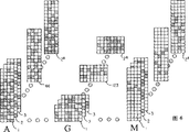
FIG. 6 illustrates a set of tiles (tiles) associated with each feature type A-M used in certain embodiments of the present invention;
FIG. 7 shows a digitally marked and labeled patch of a compressed image;
FIG. 8 illustrates patches extracted from a set of feature type patches, the patches in lighter shades having at least one flip property;
FIG. 9 shows the patch after all flipping features have been performed;
FIG. 10 shows the final image;
fig. 11 shows the best device configuration for carrying out the method of the invention.
FIG. 1A represents an image of a frontal facial portrait. In this example, the face is tilted and translated with respect to the center of the image. Other variations in face positioning and sizing within the boundaries of the image may also be encountered, depending on the source of the image. In order to obtain the maximum effect of the present invention, the size, position and orientation of the face are standardized. To operate on an image, the image is arranged in digital format, usually as a matrix of pixel values. The digital format (pixel values) of an image is derived by scanning an original image and converting the original image into digitized electrical signal values. The digital image format is then used to reproduce the display image on the display so that the normalization process is applied to the display image and to the pixel values that make up the display image to make up a normalized geometric image. The image is normalized to provide a quality that matches the template elements associated with the template (as will be described in more detail later in this specification). The process begins in FIG. 1A by first determining the centers of the left and right eyes of the face in the image. In FIG. 1B, the facial image of FIG. 1A is rotated and translated as necessary to position the centers of the left and right eyes along a predetermined horizontal axis and the images are uniformly distributed about a central longitudinal axis using well known image processing operations to form a new digitized image of the facial image representing a partially normalized geometric image. FIG. 1C shows the face image of FIG. 1B sized by scaling the image to a standard size to form a standardized geometric face image.
Referring now to FIG. 2, a method of constructing a normalized geometric image is illustrated in a flow diagram box beginning with the box labeled "select one image". The selection process is based on the availability of a frontal avatar of the person being treated with the template of the present invention. Included in the selection process is the generation of a digital matrix representation of the available images. The numerical matrix is then loaded into a system (shown in fig. 11) for display to an operator. As previously described, the operator defines the left and right eyes and performs the required rotation, translation and rescaling of the images to construct a standardized geometric image.
In more detail, with respect to the standard image of FIG. 1C and the flow chart of FIG. 2, in this embodiment of the invention, the image criteria are set as follows: the image size, width 56 pixels, height 64 pixels, eye center at 28 pixels from the image upper boundary and 8 pixels on either side of the longitudinal centerline. Determining the center of the left and right eyes is displaying the initial image to the operator who specifies the center position using a pointing device such as a mouse, tablet, light pen, or touch sensitive screen. Another approach is to use a feature search program to automate the process. The operator determines the location of the eyes and the processor fine-tunes the location by using an eye-finding search method in a smaller area around the operator determined location. The next step in normalization is to change the image so that the position of the eye is standardly determined at a predetermined position. Generally, this involves standard image processing operations of image translation, scaling and rotation.
After the image size and eye position are adjusted, the normalized geometric image is stored and a brightness normalization procedure is performed, which is represented by the boxes designated with even numbers 40-52. Standardizing the change of the brightness of the digitized image by using a three-dimensional scale; the large ones correct for asymmetric shadows from side light, the medium ones, and the small ones reduce special glare from glasses, jewelry, and skin. These programs change the average brightness level in the digitized image. Some features that are useful in discriminating between individuals tend to fade in gray scale range portraits. Therefore, in order to enhance these characteristics, a change in the brightness level, called contrast, is also adjusted.
The function represented by block 50 operates to change the average brightness of the face, i.e., the average brightness of the portion around the nose, to a predetermined value. In this preferred embodiment, the predetermined values for a light skin color person are 165, a medium skin color is 155, and a dark skin color is 135. The normalized digital image formed by block 50 is now represented by a matrix of storable pixel values corresponding to the function block 52.
Fig. 3A shows a design of a template 30 to be used with the standardized image of fig. 2. The template 30 is divided into 64 template elements labeled a through M. These elements are arranged according to 13 corresponding features of the face, for example, template element a corresponds to the hair feature at the top of the head and template element G corresponds to the eyes. Template elements with the same reference number collectively represent a feature. The remaining template elements are further described in the tables of FIGS. 4, 5A and 5B. Although the preferred embodiment of the present invention is implemented with 64 template elements and 13 features, it should be understood that these numbers may be varied as appropriate without imposing constraints on the method of the present invention. It should also be noted that certain regions of the template are not assigned any elements. These unallocated areas will not have image content based on a retrieval of information from the codebook. The method of assigning image content to these regions will be based on the assignment of contiguous regions as will be described later. The size of the template matches the size of a standardized image that is 56 pixels wide and 64 pixels high. The size of the template element is based on the size of the facial features that it is intended to represent. For example, G is the relative size of one eye in a standard image, and both elements assigned to G are placed at the position of the eye in a standard image.
In fig. 3B, the shaded template elements represent elements having a left-right flip property, which will be described later in detail.
In fig. 3C, the shaded template elements represent elements having a flip-up property, which will be described later in detail.
Another property of the template elements is connectivity. FIG. 3D shows the positions of the template elements as connecting portions by shaded areas. In this particular embodiment there are 7 element connection pairs. The connections between each pair of shadow template elements are horizontal, e.g., G located to the left of the center is connected to G located to the right of the center. Although 7 connected pairs are shown as the preferred embodiment, connections may also occur in groups of more than 2 elements and between any collection of elements having the same reference number.
The template 30 is in fact a sequence of data records, each of which describes, in the preferred embodiment, the position, size, label, left-right characteristics, top-bottom characteristics, and connections of each template element. Data records with other and/or additional factors may be generated as needed.
The template 30 records the distribution and size of the template elements. Each template element is assigned a codebook and a spatial position in the image. (Note: some portions of the template do not have template elements, and these regions will be described in detail later.) the template shown in FIG. 3A includes 64 template elements that constitute a rectangular pixel region. These template elements are assigned to one of 13 different code books (numbered a-M). These codebooks are a set of code vectors of uniform size of 4 × 16 or 8 × 8 or 8 × 5 or 4 × 10 or 4 × 6 or 8 × 4 pixels. The code vectors that make up the codebook are derived from a library of image features.
Referring to fig. 4, reference numerals a to M represent feature types of a human face. The features of the person associated with each of the labels a-M in the label row are shown one row below the label row. The remainder of fig. 4 provides information about the width and height of each labeled template element, as well as the number of occurrences and the single occurrence of each feature. The number of single occurrences represents the number of independent template elements that are connected (the connected elements are only considered to be a single occurrence at a time).
Fig. 5A and 5B illustrate template metadata records. These data records represent the attributes of each template element, i.e. for the upper left coordinate system the pixel coordinates include the data record information field, width, height, flip left and right characteristics, flip up and down characteristics, records of connected groups and feature type. If the record for the connection group is-1, then no connection occurs. Other values of the connection group identify the template elements of the group. For example, the upper two template elements D of FIG. 3D are concatenated together, and thus are given the same concatenation group number O in the concatenation group column of the tables of FIGS. 5A and 5B.
The following discussion will be made with reference to fig. 4, 5A, 5B and 6. The feature types described in fig. 4 are shown as a collection of patches in fig. 6. For example, patch 1 in the set of feature types G-eye feature-is a graphic of an eye represented as an array of pixels. For feature G, the other patches 2-2 in this setnAre other patterns of the eye. In the preferred embodiment, the number of tiles in each set is 2 for each feature typenAnd n is a positive integer. It should be noted that the tiles in the collection have visually similar characteristics when representing image features. Patches of different feature types often appear dissimilar when compared.
Fig. 7 shows an image in which template elements are assigned to tiles. Each template element of fig. 7 has an associated number corresponding to a tile representing a characteristic type of the template element. For example, template element 60 represents feature type A, and there is an associated tile numbered 46 in the collection of hair feature type tiles A in FIG. 6. Similarly, template element 62 for the eye feature type is numbered 123, which corresponds to the patch numbered 123 in the set of eye feature types labeled G in FIG. 6. Note that template elements in the same connected set (e.g., eye feature type template elements 62 and 64) have the same patch number. To facilitate identification of the connecting elements, they are printed in bold in fig. 7.
The tile number assigned to each template element in fig. 7 is used to retrieve tiles of the same number from the same-numbered set of tile feature types. The position of the retrieved patch is the same as that of the template element containing the patch number. The configuration of the patches results in the mosaic pattern of fig. 8.
Next, the selected patch is flipped (flip). Fig. 3B and 3C indicate template elements having left-right and top-bottom flip characteristics, respectively. Template elements with these flip characteristics are also indicated in the tables in fig. 5A and 5B by true/false flags. The tiles to be flipped in fig. 8 are identified by diagonal lines that represent square boxes of pixels. Fig. 9 illustrates the application of the flip feature to the tiles of fig. 8, where all of the tiles in fig. 8 corresponding to the shaded template elements in fig. 3B are flipped left-to-right, and all of the tiles in fig. 8 corresponding to the shaded template elements in fig. 3C are flipped up-to-down. It is noted that some template elements are flipped both at the same time and flipping occurs within the relevant element when the patch is converted from the patch orientation of fig. 8 to fig. 9.
The next step is to make the final image using an image processing operation based on the oriented patch mosaic of fig. 9. The mosaic of fig. 9 may have certain look-bad phenomena as a result of the construction from tiles, which may be eliminated by a combination of certain image processing algorithms. In the preferred embodiment, a combination of well-known image processing operations are used, including smoothing across tile boundaries, enhancing contrast, filling in missing image regions using linear interpolation, and adding random disturbances with three-dimensional dependencies. For the purpose of describing the smoothing operation, it is assumed that there are three consecutive pixels P1、P2And P3In the case of (1), wherein P1And P2In one patch, P3In one adjacent patch. Pixel P2Quilt (P)1+2*P2+P3) The result of/4 replaced. Contrast enhancement is obtained by determining the minimum pixel value min and the maximum pixel value max of the mosaic pattern. According to the formula:
Pnew=255×(Pcur-min)/(max-min) Each pixel value P of the mosaiccurQuilt PnewInstead ofAnd (4) changing.
Regions of the feature template that do not correspond to any template element are filled using linear interpolation. For each region, an average pixel value is calculated using the known boundary pixel values. The unknown corner opposite the known boundary is set to this average. The remaining unassigned inner pixels are computed using linear interpolation. In the preferred embodiment of the invention, there are 4 such unassigned areas, each located at a corner of a feature template.
The three-dimensional random interference to be added is determined by:
n(i,j)=v*sqrt((i-28)**2+(j-32)**2)*rand
wherein,
v is the interference magnitude
i being the column of the affected pixel
j is the row of affected pixels
rand is a pseudo-random floating point number in the range (-1 to 1). The value n (i, j) is added to the pixel at position (i, j). If the resulting pixel value is greater than 255, it is set to 255, and if less than zero, it is set to 0. Fig. 10 shows an image processed by these operations. It should be understood that other image processing operations may be employed in other situations and that the preferred embodiment should not be considered limiting.
Fig. 11 shows an apparatus 100 in which the method of the invention can be implemented. The apparatus 100 includes means 102 for converting a non-digital image, such as the photograph 80, or the negative image 82, into a digital representation of the image. Typically, the conversion is performed in a scanner 104 that outputs signals representing pixel values in analog form, and then an analog-to-digital converter 106 is used to convert the analog pixel values to digital values representing the scanned image. Other digital image sources may be input directly to the workstation 200. In the preferred device embodiment of the present invention, workstation 200 is a SUNSPARC 10, running a UNIX operating system and programmed in a standard C programming language. The program parts of the invention are given in full in the annex a and B. The display of digital images is operated by the display 202 under the control of software, a keyboard 204 and a mouse 206. Digital images may also be input into the system via a CD input 208 or other similar device. The templates produced by the method and apparatus of the present invention may be unloaded to a CD recorder 210 for storage on a CD, hard copy printed by a printer 212 for recording on a memory card (such as a transaction card), or transmitted by a modem 214 and transmission line for further processing or storage at a remote unit.
Other uses of the invention include compression of images other than portraits. Other types of features may also be represented, for example, features related to bank checks, such as bank and account numbers, as well as signatures, dollar amounts, addresses, and so forth. Like a human face, these features are usually in the same location for each check.
While the invention has been described primarily in terms of preferred embodiments, it will be apparent that many modifications can be made without departing from the essential spirit of the invention. It is therefore intended to cover in the appended claims all such modifications that are within the scope of this invention.
Parts catalog: 30 template 40-52 flow box (double number) 60 template element 62 eye feature type first template element 64 eye feature type second template element 80 photo 82 negative image 100 device 102 image digitizer 104 scanner 106 analog to digital signal converter 200 workstation 202 display 204 keyboard 206 mouse 208 CD input 210 CD recorder 212 printer 214 modem a-M codebook
Claims (10)
1. A feature template, comprising:
a plurality of template elements, each template element representing a feature of the object;
data representing attributes of each template element.
2. The characterization template of claim 1 wherein a plurality of template elements share a characterization that is representative of the object.
3. The feature template of claim 1, wherein the data representing attributes of each template element includes data indicating a connection relationship of one template element to another template element.
4. A feature template, comprising:
a region representing a feature of the object in a code form;
code bits representing the orientation of each template element relative to other template elements having the same feature type.
5. A method of constructing a feature template, comprising the steps of:
establishing the dimension of the characteristic template to adapt to the standardized image;
dividing the feature template into a plurality of feature types to accommodate the same features in the standardized image;
at least one template element is distributed to each characteristic type;
the positions of all assigned template elements in the feature template dimension are recorded to facilitate reconstruction of the feature template so constructed.
6. The method of constructing a feature template for an image of claim 5, wherein the normalized image is formed by the steps of:
acquiring an image in digital form;
features in the acquired image are adjusted and scaled to predetermined parameters.
7. The method of claim 5, further comprising the steps of: the longitudinal symmetry properties are associated with at least one template element.
8. The method of claim 5, further comprising the steps of: the horizontal symmetry property is associated with at least one template element.
9. A method as claimed in claim 5, characterized in that each template element represents a feature of an object in the standardised image, so that a representation of the standardised image can be formed from the feature template.
10. A storage medium for use in a digital signal processing system having recorded thereon a feature template constructed by the method of claim 1 to facilitate the creation of an image for display.
Applications Claiming Priority (2)
| Application Number | Priority Date | Filing Date | Title |
|---|---|---|---|
| US36135294A | 1994-12-21 | 1994-12-21 | |
| US361352 | 1994-12-21 |
Publications (1)
| Publication Number | Publication Date |
|---|---|
| CN1150283A true CN1150283A (en) | 1997-05-21 |
Family
ID=23421698
Family Applications (1)
| Application Number | Title | Priority Date | Filing Date |
|---|---|---|---|
| CN95121123A Pending CN1150283A (en) | 1994-12-21 | 1995-12-21 | Method and apparatus for formation of standardized image templates |
Country Status (6)
| Country | Link |
|---|---|
| EP (1) | EP0718788A2 (en) |
| JP (1) | JPH08249469A (en) |
| CN (1) | CN1150283A (en) |
| AR (1) | AR000239A1 (en) |
| BR (1) | BR9505966A (en) |
| ZA (1) | ZA959492B (en) |
Cited By (2)
| Publication number | Priority date | Publication date | Assignee | Title |
|---|---|---|---|---|
| CN102982501A (en) * | 2012-11-19 | 2013-03-20 | 山东神思电子技术股份有限公司 | Image sample calibration method |
| CN104021138A (en) * | 2014-04-23 | 2014-09-03 | 北京智谷睿拓技术服务有限公司 | Image retrieval method and image retrieval device |
Families Citing this family (1)
| Publication number | Priority date | Publication date | Assignee | Title |
|---|---|---|---|---|
| US10038902B2 (en) | 2009-11-06 | 2018-07-31 | Adobe Systems Incorporated | Compression of a collection of images using pattern separation and re-organization |
Family Cites Families (11)
| Publication number | Priority date | Publication date | Assignee | Title |
|---|---|---|---|---|
| GB8710737D0 (en) * | 1987-05-06 | 1987-06-10 | British Telecomm | Video image encoding |
| GB8910749D0 (en) * | 1989-05-10 | 1989-06-28 | Sherman Robin L | Methods and apparatus for obtaining information for characterising a person or animal |
| US5151951A (en) * | 1990-03-15 | 1992-09-29 | Sharp Kabushiki Kaisha | Character recognition device which divides a single character region into subregions to obtain a character code |
| JP3040466B2 (en) * | 1990-07-17 | 2000-05-15 | ブリテイッシュ・テレコミュニケーションズ・パブリック・リミテッド・カンパニー | Image processing method |
| US5237627A (en) * | 1991-06-27 | 1993-08-17 | Hewlett-Packard Company | Noise tolerant optical character recognition system |
| US5246253A (en) * | 1991-10-17 | 1993-09-21 | Mykrantz John R | Garden planning kit |
| US5331544A (en) * | 1992-04-23 | 1994-07-19 | A. C. Nielsen Company | Market research method and system for collecting retail store and shopper market research data |
| JP3364957B2 (en) * | 1992-08-24 | 2003-01-08 | カシオ計算機株式会社 | Montage creation apparatus and face image creation method |
| US5365596A (en) * | 1992-12-17 | 1994-11-15 | Philip Morris Incorporated | Methods and apparatus for automatic image inspection of continuously moving objects |
| US5574573A (en) * | 1993-10-29 | 1996-11-12 | Eastman Kodak Company | Compression method for a standardized image library |
| JPH08141212A (en) * | 1994-11-24 | 1996-06-04 | Taito Corp | Game machine with montage function |
-
1995
- 1995-11-08 ZA ZA959492A patent/ZA959492B/en unknown
- 1995-11-30 AR AR33446895A patent/AR000239A1/en unknown
- 1995-12-05 EP EP95420342A patent/EP0718788A2/en not_active Withdrawn
- 1995-12-20 BR BR9505966A patent/BR9505966A/en not_active Application Discontinuation
- 1995-12-20 JP JP7332356A patent/JPH08249469A/en active Pending
- 1995-12-21 CN CN95121123A patent/CN1150283A/en active Pending
Cited By (4)
| Publication number | Priority date | Publication date | Assignee | Title |
|---|---|---|---|---|
| CN102982501A (en) * | 2012-11-19 | 2013-03-20 | 山东神思电子技术股份有限公司 | Image sample calibration method |
| CN102982501B (en) * | 2012-11-19 | 2015-07-01 | 山东神思电子技术股份有限公司 | Image sample calibration method |
| CN104021138A (en) * | 2014-04-23 | 2014-09-03 | 北京智谷睿拓技术服务有限公司 | Image retrieval method and image retrieval device |
| CN104021138B (en) * | 2014-04-23 | 2017-09-01 | 北京智谷睿拓技术服务有限公司 | Image search method and image retrieving apparatus |
Also Published As
| Publication number | Publication date |
|---|---|
| ZA959492B (en) | 1996-07-10 |
| JPH08249469A (en) | 1996-09-27 |
| BR9505966A (en) | 1997-12-23 |
| EP0718788A3 (en) | 1996-07-17 |
| AR000239A1 (en) | 1997-05-28 |
| EP0718788A2 (en) | 1996-06-26 |
Similar Documents
| Publication | Publication Date | Title |
|---|---|---|
| US11010955B2 (en) | Point cloud mapping | |
| US10410087B2 (en) | Automated methods and systems for locating document subimages in images to facilitate extraction of information from the located document subimages | |
| KR102709925B1 (en) | Projection-based mesh compression | |
| AU632333B2 (en) | Method and apparatus for processing digital data | |
| US7643683B2 (en) | Generation of image database for multifeatured objects | |
| US5963670A (en) | Method and apparatus for classifying and identifying images | |
| US7583846B2 (en) | Texture image compressing device and method, texture image decompressing device and method, data structures and storage medium | |
| US8417029B2 (en) | Image processing apparatus and method, including fill-up processing | |
| US20070013713A1 (en) | Apparatus and method for synthesizing multi-dimensional texture | |
| US20050147280A1 (en) | System and method for face recognition using synthesized images | |
| Wang et al. | Factoring repeated content within and among images | |
| JP2004086891A (en) | Object detection method in digital image | |
| US20040165787A1 (en) | Image region filling by example-based tiling | |
| CN1447955A (en) | Appts. and method for generating synthetic face image based on shape information about face image | |
| CN113658032B (en) | Image watermark encryption and decryption method and system based on deep learning and image processing | |
| JP2001186516A (en) | Method and system for coding decoding image data | |
| JP2003244447A (en) | Image processor and image processing method | |
| US7961941B2 (en) | Color form dropout using dynamic geometric solid thresholding | |
| CN1150283A (en) | Method and apparatus for formation of standardized image templates | |
| CN1290064C (en) | Equipment and method for synthetizing higher-dimensional grain | |
| Fu | Color image quality measures and retrieval | |
| EP0718807B1 (en) | Method for compressing and decompressing standardized portrait images | |
| JP3618234B2 (en) | 3D model compression method and 3D model image generation method | |
| CN108665434A (en) | Image combining method and device | |
| Lin et al. | Computer-aided Approaches to Cultural Heritage Restoration |
Legal Events
| Date | Code | Title | Description |
|---|---|---|---|
| C06 | Publication | ||
| PB01 | Publication | ||
| C10 | Entry into substantive examination | ||
| SE01 | Entry into force of request for substantive examination | ||
| C01 | Deemed withdrawal of patent application (patent law 1993) | ||
| WD01 | Invention patent application deemed withdrawn after publication |