CN114994762A - A Sparse Domain Seismic Diffraction Wave Separation Method - Google Patents
A Sparse Domain Seismic Diffraction Wave Separation Method Download PDFInfo
- Publication number
- CN114994762A CN114994762A CN202210622220.2A CN202210622220A CN114994762A CN 114994762 A CN114994762 A CN 114994762A CN 202210622220 A CN202210622220 A CN 202210622220A CN 114994762 A CN114994762 A CN 114994762A
- Authority
- CN
- China
- Prior art keywords
- diffracted wave
- atom
- sparse
- diffracted
- data
- Prior art date
- Legal status (The legal status is an assumption and is not a legal conclusion. Google has not performed a legal analysis and makes no representation as to the accuracy of the status listed.)
- Granted
Links
Images


Classifications
-
- G—PHYSICS
- G01—MEASURING; TESTING
- G01V—GEOPHYSICS; GRAVITATIONAL MEASUREMENTS; DETECTING MASSES OR OBJECTS; TAGS
- G01V1/00—Seismology; Seismic or acoustic prospecting or detecting
- G01V1/28—Processing seismic data, e.g. for interpretation or for event detection
- G01V1/36—Effecting static or dynamic corrections on records, e.g. correcting spread; Correlating seismic signals; Eliminating effects of unwanted energy
-
- G—PHYSICS
- G01—MEASURING; TESTING
- G01V—GEOPHYSICS; GRAVITATIONAL MEASUREMENTS; DETECTING MASSES OR OBJECTS; TAGS
- G01V2210/00—Details of seismic processing or analysis
- G01V2210/30—Noise handling
Landscapes
- Engineering & Computer Science (AREA)
- Remote Sensing (AREA)
- Physics & Mathematics (AREA)
- Life Sciences & Earth Sciences (AREA)
- Acoustics & Sound (AREA)
- Environmental & Geological Engineering (AREA)
- Geology (AREA)
- General Life Sciences & Earth Sciences (AREA)
- General Physics & Mathematics (AREA)
- Geophysics (AREA)
- Geophysics And Detection Of Objects (AREA)
Abstract
Description
技术领域technical field
本发明涉及地震勘探多次波压制技术领域,更具体地,涉及一种稀疏域地震绕射波分离方法。The invention relates to the technical field of multiple wave suppression in seismic exploration, and more particularly, to a method for separating seismic diffraction waves in a sparse domain.
背景技术Background technique
随着勘探开发的深入,小尺度、高分辨地震成像在高精度地震勘探中的意义日益显得重要。地震勘探的重点在于研究断层、河道、裂缝、尖灭点以及溶蚀孔洞型储集体等横向非均质体相关的信息,这些目标地质体具有尺度小、形态不规则、空间非均质性强等特点,与反射波不一样,地震波在传播过程中遇到这些小尺度地质体,形成二次震源产生大量绕射波,这些绕射波与反射波相比,无论是动力学还是运动学都具有明显差异。因此,利用好绕射波成像对于横向非均质体勘探具有非常重要的意义,同时还可以更好地探明构造发育带,寻找有利圈闭。绕射波振幅相对于反射波弱很多,通常被淹没在反射波信息中难以识别,常规地震处理主要以一次反射波为目标对象,通常在噪音压制过程中对连续反射以外的绕射波产生一定损伤,因此针对绕射波的单独成像技术被发展起来。With the deepening of exploration and development, the significance of small-scale and high-resolution seismic imaging in high-precision seismic exploration has become increasingly important. The focus of seismic exploration is to study information related to laterally heterogeneous bodies such as faults, channels, fractures, pinch-out points, and dissolved vug-type reservoirs. These target geological bodies have small scales, irregular shapes, and strong spatial heterogeneity. Different from reflected waves, seismic waves encounter these small-scale geological bodies in the process of propagation, forming a secondary source to generate a large number of diffracted waves. Compared with reflected waves, these diffracted waves have different dynamics and kinematics. Significant differences. Therefore, making good use of diffraction wave imaging is of great significance for the exploration of lateral heterogeneity, and at the same time, it can better identify structural development zones and find favorable traps. The amplitude of the diffracted wave is much weaker than that of the reflected wave, and it is usually submerged in the reflected wave information and difficult to identify. Conventional seismic processing mainly takes the primary reflected wave as the target object, and usually produces a certain amount of diffracted waves other than the continuous reflection during the noise suppression process. damage, so a separate imaging technique for diffracted waves was developed.
绕射波分离成像可以分为“直接法”和“间接法”绕射波成像,前者是在偏移过程中或者偏移后依据反射波与绕射波特征差异,直接对绕射波进行成像,后者是在偏移前道集波场中分离出绕射波,然后对分离出来绕射波进行偏移成像。“直接法”具有计算效率高的特点,而偏移前道集绕射波分离技术多采用迭代反演方法且波场分离的数据量非常大,绕射波分离耗时非常长、计算效率低下。此外,偏移前道集绕射波分离的绕射波能量比较弱,在低信噪比地区,绕射波信号往往难以识别,如何从淹没在强反射数据中分离出可靠的弱绕射波信号也一直是绕射波分离成像的技术难点。Diffraction wave separation imaging can be divided into "direct method" and "indirect method" diffraction wave imaging. The former is to directly image the diffracted wave according to the characteristic difference between the reflected wave and the diffracted wave during the migration process or after the migration. , the latter is to separate diffracted waves in the gather wave field before migration, and then perform migration imaging on the separated diffracted waves. The "direct method" has the characteristics of high computational efficiency, while the pre-migration gather diffraction wave separation technology mostly adopts the iterative inversion method, and the amount of data for wave field separation is very large, the diffraction wave separation takes a long time, and the computational efficiency is low. . In addition, the energy of the diffracted waves separated by the diffracted waves of the gathers before migration is relatively weak. In the low signal-to-noise ratio area, the diffracted wave signals are often difficult to identify. How to separate the reliable weak diffracted waves from the submerged strong reflection data? Signal has always been a technical difficulty in diffraction wave separation imaging.
偏移前道集绕射波分离方法主要是利用反射波与绕射波运动学和动力学特征差异,其常用的技术主要有利用反射波与绕射波振幅能量差异的奇异值滤波技术、利用地震波走时差异的倾角滤波或者Radon变换滤波技术,这些技术均很难较好地解决绕射波顶点及两翼同时分离,此外对于低信噪比数据,受噪音的影响,绕射波分离效果也往往不是很理想。The diffracted wave separation method of gather before migration mainly utilizes the difference of kinematics and dynamic characteristics of reflected wave and diffracted wave. The dip filtering or Radon transform filtering technology of seismic wave travel time difference is difficult to solve the simultaneous separation of the diffraction wave vertex and the two wings. In addition, for low signal-to-noise ratio data, due to the influence of noise, the diffraction wave separation effect is often Not ideal.
如现有技术公开了一种基于近道镶边稀疏Radon变换的绕射波分离方法,利用高效率的稀疏Radon变换对含有绕射波的叠前道集进行波场分离,得到分离出的反射波和绕射波,虽然该分离方法能够有效减少Radon变换的近道边缘效应,提高反射波和绕射波在Radon域中的可分离程度,但是该分离方法仍存在抗躁性不高,分离效果不佳的问题。For example, the prior art discloses a method for separating diffracted waves based on the sparse Radon transform of the near-track fringe. The high-efficiency sparse Radon transform is used to separate the wave field of the pre-stack gathers containing diffracted waves, and the separated reflected waves are obtained. and diffracted waves, although this separation method can effectively reduce the near-channel edge effect of Radon transform and improve the degree of separability of reflected and diffracted waves in the Radon domain, but the separation method still has low noise resistance and poor separation effect. good question.
发明内容SUMMARY OF THE INVENTION
本发明为克服上述现有技术所述的绕射波分离技术受噪音影响,绕射波分离效果不是很理想的技术问题,提供一种抗噪性较高、绕射波信号分离较为彻底的稀疏域地震绕射波分离方法。In order to overcome the technical problem that the diffraction wave separation technology described in the above-mentioned prior art is affected by noise and the diffraction wave separation effect is not very ideal, the present invention provides a sparse system with high noise resistance and relatively thorough diffraction wave signal separation. Domain Seismic Diffraction Wave Separation Method.
为解决上述技术问题,本发明采用的技术方案是:一种稀疏域地震绕射波分离方法,所述方法包括:In order to solve the above-mentioned technical problems, the technical solution adopted in the present invention is: a method for separating seismic diffraction waves in a sparse domain, the method comprising:
步骤一:利用绕射波的时距曲线为双曲线、振幅能量与传播距离成反比的理论构建不同曲率的绕射波信号,生成绕射波信号原子库;Step 1: Use the theory that the time-distance curve of the diffracted wave is a hyperbola, and the amplitude energy is inversely proportional to the propagation distance to construct diffracted wave signals with different curvatures, and generate a diffracted wave signal atom library;
步骤二:利用匹配追踪算法在步骤一中得到的绕射波信号原子库中迭代分解搜寻信号原子,得到稀疏的绕射波信号原子;并在匹配追踪分解过程中每一次迭代采用最小二乘方法求解稀疏信号原子的系数;Step 2: Use the matching pursuit algorithm to iteratively decompose and search for signal atoms in the diffraction wave signal atom library obtained in
步骤三:通过对步骤二中得到的绕射波信号原子及其系数进行加权叠加得到分离后的绕射波数据。Step 3: Obtain the separated diffracted wave data by weighting and superimposing the diffracted wave signal atoms and their coefficients obtained in the second step.
本发明采用完备绕射波信号原子库在稀疏域进行绕射波分解,其抗噪性较好,对于低信噪比数据应用效果显著,同时还可以较好地解决绕射波顶点与两翼分离完整性问题,相对于传统的匹配追踪技术,采用迭代匹配追踪求解绕射波信号原子的系数,绕射波信号分解更加彻底。The invention adopts a complete diffraction wave signal atom library to decompose the diffraction wave in the sparse domain, and has good anti-noise performance, and has a significant application effect on data with a low signal-to-noise ratio, and can also better solve the separation of the diffraction wave apex and the two wings. For the integrity problem, compared with the traditional matching pursuit technology, the iterative matching pursuit is used to solve the coefficients of the diffracted wave signal atoms, and the diffracted wave signal is decomposed more thoroughly.
进一步地,所述步骤一中在生成绕射波信号原子库之前需输入数据并对数据进行重排,具体为:输入炮集或者共中心点道集,并将输入的炮集或者共中心点道集重新按照偏移距进行排列,得到共偏移距道集d;同时输入均方根速度场vrms。Further, in the
进一步地,所述步骤一中在输入数据并对数据进行重排之后,设定绕射波分离过程中的参数,包括绕射波信号原子的曲率范围[σ1~σ2],曲率间隔Δσ,最小二乘求解阻尼系数ε,绕射波信号原子与实际数据的最小可接受相关系数阈值αacp,最大可接受残差百分比ζacp,匹配追踪最大迭代次数N。Further, in the
进一步地,所述步骤一中生成绕射波信号原子库Atom(σ,t0,x),其中,Further, in the
绕射波信号的时距曲线计算公式采用双曲线公式,
进一步地,所述步骤一中生成绕射波信号原子库Atom(σ,t0,x),其中,Further, in the
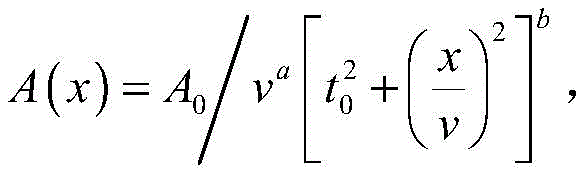
绕射波的振幅计算采用公式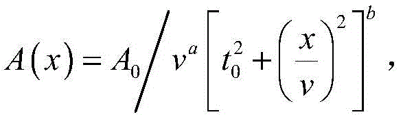
进一步地,所述步骤一中生成绕射波信号原子库Atom(σ,t0,x)还包括如下操作:Further, generating the atomic library Atom(σ,t 0 ,x) of the diffracted wave signal in the
根据搜索到的绕射波信号进行最小二乘拟合,即||A(x)-Areal(x)||→min,Areal(x)为实际绕射波数据的振幅值。The least squares fitting is performed according to the searched diffracted wave signal, namely ||A(x)-A real (x)||→min, A real (x) is the amplitude value of the actual diffracted wave data.
进一步地,所述步骤二中搜寻绕射波信号原子的具体操作为:Further, the specific operation of searching for diffracted wave signal atoms in the second step is:
(I)、设定输入数据d;(I), set input data d;
初始化残差数据r0=d,输出绕射波地震数据ds=0,搜索到的绕射波原子库Atomsearched=Φ,迭代次数k=0;Initialize residual data r 0 =d, output diffraction wave seismic data d s =0, searched diffraction wave atom library Atom searched =Φ, iteration number k = 0;
时间样点循环处理;Time sample loop processing;
地震道数循环处理;Seismic trace number loop processing;
(II)、匹配追踪循环:k≤N;(II), matching tracking loop: k≤N;
(III)、计算绕射波信号原子库Atom(σ,t0,x)与数据残差rk的相关系数
(Ⅳ)、计算相关系数C(σ)最大的索引值m=argmax(C(σi)),i=1,2,...,N,如果C(σm)>αacp则进入步骤(Ⅴ),否则结束匹配追踪循环;(IV), calculate the maximum index value m=argmax(C(σ i )) of the correlation coefficient C(σ i ), i=1,2,...,N, if C(σ m )>α acp then enter the step (V), otherwise end the matching tracking loop;
(Ⅴ)、将搜索到的绕射波信号原子加入到已搜索到的原子库中,Atomsearched=Atomsearched∪Atom(σm,t0,x),同时把从下一次迭代的原子库中排除,

进一步地,所述步骤二中求解稀疏信号原子的系数为求解绕射波原子全局最优化系数,采用的方程为超定方程。Further, in the second step, the coefficient of solving the sparse signal atom is to solve the global optimization coefficient of the diffracted wave atom, and the equation used is an overdetermined equation.
进一步地,所述步骤二中求解稀疏信号原子的系数具体操作为:Further, the specific operation of solving the coefficients of the sparse signal atoms in the second step is:
令L=Atomsearched,采用最小二乘法求取搜索到的绕射波原子的全局最优化系数ysearched=(LTL+εI)-1LTd,T表示矩阵转置,I表示单位对角阵,ε表示最小二乘求解阻尼系数,d表示共偏移距道集。Let L=Atom searched , use the least square method to obtain the global optimization coefficient y searched =(L T L+εI) -1 L T d, where T represents matrix transposition, and I represents unit pair Angular matrix, ε represents the least squares solution damping coefficient, d represents the common offset gather.
进一步的,所述步骤三的具体操作为:Further, the specific operation of the step 3 is:
重构绕射波地震数据ds=Lysearched;Reconstructed diffracted seismic data d s =Ly searched ;
更新残差rk+1=d-ds,计算残差的百分比系数
匹配追踪循环结束后;After the matching tracking loop ends;
地震道数循环处理结束;The seismic trace cycle processing ends;
时间样点循环处理结束;The time sample loop processing ends;
输出绕射波地震数据ds。Diffraction wave seismic data d s is output.
与现有技术相比,本发明的有益效果是:Compared with the prior art, the beneficial effects of the present invention are:
1)本发明中本发明采用完备的绕射波信号原子库在稀疏域进行绕射波分解,因此其抗噪性非常好,对于低信噪比数据应用效果显著,同时还可以较好地解决绕射波顶点与两翼分离完整性问题;1) In the present invention, the present invention uses a complete diffraction wave signal atom library to perform diffraction wave decomposition in the sparse domain, so its anti-noise performance is very good, and it has a significant application effect for low signal-to-noise ratio data, and can also solve the problem well. The integrity of the separation between the diffraction wave apex and the two wings;
2)本发明相对于传统的匹配追踪技术,采用迭代匹配追踪求解绕射波信号原子的系数,绕射波信号分解更加彻底;2) Compared with the traditional matching tracking technology, the present invention adopts iterative matching tracking to solve the coefficient of the diffracted wave signal atom, and the diffraction wave signal is decomposed more thoroughly;
3)本发明整体方法简单,计算效率很高,作为地震数据处理的常规流程之一,其应用范围广泛,值得推广应用。3) The overall method of the present invention is simple and the calculation efficiency is high. As one of the conventional procedures of seismic data processing, it has a wide range of applications and is worthy of popularization and application.
附图说明Description of drawings
图1是本发明稀疏域地震绕射波分离方法的流程图;Fig. 1 is the flow chart of the present invention's sparse domain seismic diffraction wave separation method;
图2是本发明稀疏域地震绕射波分离方法的具体流程图;Fig. 2 is the concrete flow chart of sparse domain seismic diffraction wave separation method of the present invention;
图3是本发明稀疏域地震绕射波分离方法无噪音数据分离效果图;Fig. 3 is a noise-free data separation effect diagram of the sparse domain seismic diffraction wave separation method of the present invention;
图4是本发明稀疏域地震绕射波分离方法绕射波信号与噪音信噪比为-6db时分离效果图;Fig. 4 is the separation effect diagram when the diffraction wave signal and the noise signal-to-noise ratio of the sparse domain seismic diffraction wave separation method of the present invention are -6db;
图5是本发明稀疏域地震绕射波分离方法绕射波信号与噪音信噪比为-20db时分离效果图。Fig. 5 is a diagram showing the separation effect of the method for separating the diffracted wave in the sparse domain of the present invention when the signal-to-noise ratio of the diffracted wave signal to the noise is -20db.
具体实施方式Detailed ways
附图仅用于示例性说明,不能理解为对本专利的限制;为了更好说明本实施例,附图某些部件会有省略、放大或缩小,并不代表实际产品的尺寸;对于本领域技术人员来说,附图中某些公知结构及其说明可能省略是可以理解的。附图中描述位置关系仅用于示例性说明,不能理解为对本专利的限制。The accompanying drawings are for illustrative purposes only, and should not be construed as limitations on this patent; in order to better illustrate the present embodiment, some parts of the accompanying drawings may be omitted, enlarged or reduced, and do not represent the size of the actual product; for those skilled in the art It is understandable to the artisan that certain well-known structures and descriptions thereof may be omitted from the drawings. The positional relationships described in the drawings are only for exemplary illustration, and should not be construed as a limitation on the present patent.
本发明实施例的附图中相同或相似的标号对应相同或相似的部件;在本发明的描述中,需要理解的是,若有术语“上”、“下”、“左”、“右”“长”“短”等指示的方位或位置关系为基于附图所示的方位或位置关系,仅是为了便于描述本发明和简化描述,而不是指示或暗示所指的装置或元件必须具有特定的方位、以特定的方位构造和操作,因此附图中描述位置关系的用语仅用于示例性说明,不能理解为对本专利的限制,对于本领域的普通技术人员而言,可以根据具体情况理解上述术语的具体含义。The same or similar numbers in the drawings of the embodiments of the present invention correspond to the same or similar components; in the description of the present invention, it should be understood that if there are terms “upper”, “lower”, “left” and “right” The orientation or positional relationship indicated by "long" and "short" is based on the orientation or positional relationship shown in the drawings, and is only for the convenience of describing the present invention and simplifying the description, rather than indicating or implying that the indicated device or element must have a specific Therefore, the terms describing the positional relationship in the accompanying drawings are only used for exemplary illustration, and should not be construed as a limitation on this patent. For those of ordinary skill in the art, they can understand according to specific circumstances. The specific meanings of the above terms.
下面通过具体实施例,并结合附图,对本发明的技术方案作进一步的具体描述:Below by specific embodiment, and in conjunction with accompanying drawing, the technical scheme of the present invention is further described in detail:
实施例1Example 1
如图1-图2所示为一种稀疏域地震绕射波分离方法,包括:As shown in Figure 1-Figure 2, a sparse domain seismic diffraction wave separation method includes:
步骤一:利用绕射波的时距曲线为双曲线、振幅能量与传播距离成反比的理论构建不同曲率的绕射波信号,生成绕射波信号原子库;Step 1: Use the theory that the time-distance curve of the diffracted wave is a hyperbola, and the amplitude energy is inversely proportional to the propagation distance to construct diffracted wave signals with different curvatures, and generate a diffracted wave signal atom library;
步骤二:利用匹配追踪算法在步骤一中得到的绕射波信号原子库中迭代分解搜寻信号原子,得到稀疏的绕射波信号原子;并在匹配追踪分解过程中每一次迭代采用最小二乘方法求解稀疏信号原子的系数;Step 2: Use the matching pursuit algorithm to iteratively decompose and search for signal atoms in the diffraction wave signal atom library obtained in
步骤三:通过对步骤二中得到的绕射波信号原子及其系数进行加权叠加得到分离后的绕射波数据。Step 3: Obtain the separated diffracted wave data by weighting and superimposing the diffracted wave signal atoms and their coefficients obtained in the second step.
上述步骤一的具体操作为:输入数据及数据重排:将输入的炮集或者共中心点道集重新按照偏移距进行排列,得到共偏移距道集d,其中炮集和共中心点道集均为现有专业名词,在此不再进行赘述;同时输入均方根速度场vrms;数据重排的主要目的是充分利用绕射波信号在共偏移距域具有良好的双曲特征,便于利用双曲绕射波信号原子库进行匹配追踪分解,均方根速度场用于后续绕射波信号原子库振幅拟合;The specific operations of the above-mentioned
设定绕射波分离过程中的参数:绕射波信号原子的曲率范围[σ1~σ2],曲率间隔Δσ,最小二乘求解阻尼系数ε,绕射波信号原子与实际数据的最小可接受相关系数阈值αacp,最大可接受残差百分比ζacp,由于受振幅绝对大小的影响,本发明的残差定义采用适应性更加广泛的相对的百分比衡量残差能量的大小,匹配追踪最大迭代次数N;Set the parameters in the process of diffracted wave separation: the curvature range of the diffracted wave signal atoms [σ 1 ~σ 2 ], the curvature interval Δσ, the least squares solution damping coefficient ε, and the minimum compatibility between the diffracted wave signal atoms and the actual data. Acceptance correlation coefficient threshold α acp , maximum acceptable residual error percentage ζ acp , due to the influence of the absolute magnitude of the amplitude, the residual error definition of the present invention adopts a more widely adaptable relative percentage to measure the size of the residual error energy, and matches the maximum iteration of tracking times N;
生成绕射波信号原子库Atom(σ,t0,x),绕射波信号原子库中的每个原子由一条双曲线走时及对应的振幅组成,仅仅是在双曲线的位置具有值,其中,绕射波信号的时距曲线计算公式采用双曲线公式,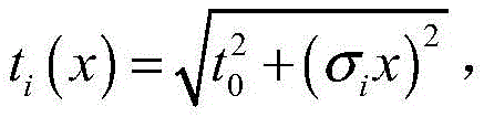
上述步骤二中搜寻绕射波信号原子的具体操作为:The specific operation of searching for diffracted wave signal atoms in the
(I)、设定初始参数:(I), set the initial parameters:
初始化残差数据r0=d,输出数据ds=0,搜索到的绕射波原子库Atomsearched=Φ,迭代次数k=0;Initialize residual data r 0 =d, output data d s =0, searched diffraction wave atom library Atom searched =Φ, iteration number k = 0;
时间样点循环处理;Time sample loop processing;
地震道数循环处理;Seismic trace number loop processing;
(II)、匹配追踪循环:k≤N;(II), matching tracking loop: k≤N;
(III)、计算绕射波信号原子库Atom(σ,t0,x)与数据残差rk的相关系数
(Ⅳ)、计算相关系数最大的索引值m=argmax(C(σi)),i=1,2,...,N,如果C(σm)>αacp则进入步骤(Ⅴ),否则结束匹配追踪循环;(IV), calculate the index value with the largest correlation coefficient m=argmax(C(σ i )), i=1,2,...,N, if C(σ m )>α acp , then enter step (V), Otherwise, end the matching tracking loop;
(Ⅴ)、将搜索到的绕射波信号原子加入到已搜索到的原子库中,Atomsearched=Atomsearched∪Atom(σm,t0,x),同时把从下一次迭代的原子库中排除,

上述步骤二中求解稀疏信号原子的系数具体操作为:The specific operations for solving the coefficients of the sparse signal atoms in the
令L=Atomsearched,相对于稀疏的绕射波原子,绕射波数据的采样点远大于其数量,因此求解绕射波原子全局最优化系数的方程为超定方程,采用最小二乘法求取搜索到的绕射波原子的全局最优化系数解表示为:ysearched=(LTL+εI)-1LTd,T表示矩阵转置,I表示单位对角阵,ε表示最小二乘求解阻尼系数,d表示共偏移距道集;Let L=Atom searched , compared to the sparse diffracted wave atoms, the sampling points of the diffracted wave data are much larger than the number, so the equation for solving the global optimization coefficient of the diffracted wave atom is an overdetermined equation, which is obtained by the least squares method The global optimization coefficient solution of the searched diffracted wave atoms is expressed as: y searched = (L T L+εI) -1 L T d, where T represents matrix transpose, I represents unit diagonal matrix, and ε represents least squares Solve the damping coefficient, d represents the common offset gather;
上述步骤三的具体操作为:The specific operations of the third step above are as follows:
重构绕射波地震数据ds=Lysearched;Reconstructed diffracted seismic data d s =Ly searched ;
更新残差rk+1=d-ds,计算残差的百分比系数
匹配追踪循环结束;The matching tracking loop ends;
地震道数循环处理结束;The seismic trace cycle processing ends;
时间样点循环处理结束。The time sample loop processing ends.
输出绕射波地震数据ds。Diffraction wave seismic data d s is output.
本发明采用完备绕射波信号原子库在稀疏域进行绕射波分解,其抗噪性比较好,对于低信噪比数据应用效果较显著,同时还可以较好地解决绕射波顶点与两翼分离完整性问题,使得绕射波信号分离较为完整,另外相对于传统的匹配追踪技术,本发明采用迭代匹配追踪求解绕射波信号原子的系数,绕射波信号分解更加彻底。本发明整体方法简单,计算效率很高,作为地震数据处理的常规流程之一,其应用范围广泛,值得应用推广。The invention adopts the complete diffraction wave signal atom library to decompose the diffraction wave in the sparse domain, and has good anti-noise performance, and has a significant application effect for low signal-to-noise ratio data, and can also better solve the diffraction wave apex and the two wings. The separation integrity problem makes the diffraction wave signal separation more complete. In addition, compared with the traditional matching tracking technology, the present invention adopts iterative matching tracking to solve the coefficients of the diffraction wave signal atoms, and the diffraction wave signal is decomposed more thoroughly. The overall method of the invention is simple and the calculation efficiency is high. As one of the conventional processes of seismic data processing, the invention has a wide range of applications and is worthy of application and promotion.
下面通过具体的数据试验来说明本发明方法的优越性,具体操作为:本发明试验数据采用合成地震数据,数据的道间距为12.5m,数据中共有8组相邻一定间距的绕射波,绕射的间距变化分别为12.5m、25m、37.5m、50m、62.5m、75m、87.5m、100m。左支绕射波顶点处的反射系数为0.0023,右支绕射波的顶点处的反射系数为0.0028,数据中还包含上下两个水平层状界面,其反射系数分别为0.01、0.012。The superiority of the method of the present invention is described below through specific data experiments, and the specific operations are as follows: the experimental data of the present invention adopts synthetic seismic data, the track spacing of the data is 12.5m, and there are 8 groups of adjacent diffraction waves with a certain spacing in the data, The diffraction spacing changes are 12.5m, 25m, 37.5m, 50m, 62.5m, 75m, 87.5m, and 100m, respectively. The reflection coefficient at the vertex of the left diffracted wave is 0.0023, and the reflection coefficient at the vertex of the right diffracted wave is 0.0028. The data also includes two horizontal layered interfaces, whose reflection coefficients are 0.01 and 0.012, respectively.
为了测试本发明绕射波分离效果,本实施例采用无噪音的数据进行试验。试验结果分别包含(A)、(B)、(C)、(D)四个子图,其数据分别为:图(A)为输入数据图、图(B)为分离的绕射波数据图、图(C)为绕射波以外其它数据图、图(D为分离绕射波与真实绕射波之间的差值图。In order to test the diffractive wave separation effect of the present invention, this embodiment uses noise-free data for testing. The test results include (A), (B), (C), and (D) four sub-graphs, respectively. The data are: Figure (A) is the input data graph, Figure (B) is the separated diffraction wave data graph, Figure (C) is a graph of data other than the diffracted wave, and Figure (D) is the difference between the separated diffracted wave and the real diffracted wave.
如图3可以看到,反射波信号与绕射波信号完全分离,分离的绕射波信号比较完整彻底,与真实绕射波信号差值非常小,难以通过肉眼识别。As can be seen in Figure 3, the reflected wave signal is completely separated from the diffracted wave signal, and the separated diffracted wave signal is relatively complete and complete, and the difference from the real diffracted wave signal is very small, making it difficult to identify with the naked eye.
实施例2Example 2
本实施例为一种稀疏域地震绕射波分离方法的实施例2,本实施例与实施例1的不同之处在于:本实施例中试验数据采用合成地震数据,数据的道间距为12.5m,数据中共有8组相邻一定间距的绕射波,绕射的间距变化分别为12.5m、25m、37.5m、50m、62.5m、75m、87.5m、100m。左支绕射波顶点处的反射系数为0.0023,右支绕射波的顶点处的反射系数为0.0028,数据中还包含上下两个水平层状界面,其反射系数分别为0.01、0.012。This embodiment is
为了测试本发明绕射波分离效果,本实施例采用信噪比分别为12db的数据进行试验。试验结果分别包含(A)、(B)、(C)、(D)四个子图,其数据分别为:图(A)为输入数据图、图(B)为分离的绕射波数据图、图(C)为绕射波以外其它数据图、图(D为分离绕射波与真实绕射波之间的差值图。In order to test the diffracted wave separation effect of the present invention, data with a signal-to-noise ratio of 12db is used for testing in this embodiment. The test results include (A), (B), (C), and (D) four sub-graphs, respectively. The data are: Figure (A) is the input data graph, Figure (B) is the separated diffraction wave data graph, Figure (C) is a graph of data other than the diffracted wave, and Figure (D) is the difference between the separated diffracted wave and the real diffracted wave.
如图4可以看到,由于绕射波两翼随着距离的增大其振幅值逐渐衰减,相对于绕射波顶点处,其绕射波信号变得难以识别,如果基于斜率进行分离,由于其信噪比较低,绕射波信号往往难以较好地分离。而本发明方法绕射波信号分离依然比较完整彻底,从图4(D)中分离绕射波与真实绕射波差值也可以看到,二者仅存在微弱的差异。As can be seen in Figure 4, since the amplitude value of the two wings of the diffracted wave gradually decays with the increase of the distance, the diffracted wave signal becomes difficult to identify relative to the vertex of the diffracted wave. If the separation is based on the slope, due to its The signal-to-noise ratio is low, and diffracted wave signals are often difficult to separate well. However, the method of the present invention still separates the diffracted wave signal completely and completely. From Fig. 4(D), it can also be seen that the difference between the diffracted wave and the real diffracted wave is separated, and there is only a slight difference between the two.
实施例3Example 3
本实施例为一种稀疏域地震绕射波分离方法的实施例3,本实施例与实施例1的不同之处在于:本实施例中试验数据采用合成地震数据,数据的道间距为12.5m,数据中共有8组相邻一定间距的绕射波,绕射的间距变化分别为12.5m、25m、37.5m、50m、62.5m、75m、87.5m、100m。左支绕射波顶点处的反射系数为0.0023,右支绕射波的顶点处的反射系数为0.0028,数据中还包含上下两个水平层状界面,其反射系数分别为0.01、0.012。This embodiment is Embodiment 3 of a method for separating seismic diffraction waves in a sparse domain. The difference between this embodiment and
为了测试本发明绕射波分离效果,本实施例采用信噪比分别为6db的数据进行试验。试验结果分别包含(A)、(B)、(C)、(D)四个子图,其数据分别为:图(A)为输入数据图、图(B)为分离的绕射波数据图、图(C)为绕射波以外其它数据图、图(D为分离绕射波与真实绕射波之间的差值图。In order to test the diffraction wave separation effect of the present invention, data with a signal-to-noise ratio of 6db is used for testing in this embodiment. The test results include (A), (B), (C), and (D) four sub-graphs, respectively. The data are: Figure (A) is the input data graph, Figure (B) is the separated diffraction wave data graph, Figure (C) is a graph of data other than the diffracted wave, and Figure (D) is the difference between the separated diffracted wave and the real diffracted wave.
如图5可以看到,由于噪音能量进一步变强,绕射波两翼的信号基本上无法识别,仅绕射波顶点附近可以看到较为清楚的绕射波信号,从分离结果上来看,绕射波分离效果依然比较理想,真实绕射波与分离绕射波虽然差值虽然能量变强,但是相对于真实绕射波能量,其能量值依然比较微弱。As can be seen in Figure 5, due to the further increase of noise energy, the signals of the two wings of the diffracted wave are basically unrecognizable, and only the clearer diffracted wave signal can be seen near the vertex of the diffracted wave. The wave separation effect is still ideal. Although the difference between the real diffracted wave and the separated diffracted wave becomes stronger, its energy value is still relatively weak compared to the energy of the real diffracted wave.
显然,本发明的上述实施例仅仅是为清楚地说明本发明所作的举例,而并非是对本发明的实施方式的限定。对于所属领域的普通技术人员来说,在上述说明的基础上还可以做出其它不同形式的变化或变动。这里无需也无法对所有的实施方式予以穷举。凡在本发明的精神和原则之内所作的任何修改、等同替换和改进等,均应包含在本发明权利要求的保护范围之内。Obviously, the above-mentioned embodiments of the present invention are only examples for clearly illustrating the present invention, and are not intended to limit the embodiments of the present invention. For those of ordinary skill in the art, changes or modifications in other different forms can also be made on the basis of the above description. There is no need and cannot be exhaustive of all implementations here. Any modification, equivalent replacement and improvement made within the spirit and principle of the present invention shall be included within the protection scope of the claims of the present invention.
Claims (10)


Priority Applications (1)
| Application Number | Priority Date | Filing Date | Title |
|---|---|---|---|
| CN202210622220.2A CN114994762B (en) | 2022-06-02 | 2022-06-02 | A sparse domain seismic diffraction wave separation method |
Applications Claiming Priority (1)
| Application Number | Priority Date | Filing Date | Title |
|---|---|---|---|
| CN202210622220.2A CN114994762B (en) | 2022-06-02 | 2022-06-02 | A sparse domain seismic diffraction wave separation method |
Publications (2)
| Publication Number | Publication Date |
|---|---|
| CN114994762A true CN114994762A (en) | 2022-09-02 |
| CN114994762B CN114994762B (en) | 2025-05-06 |
Family
ID=83030513
Family Applications (1)
| Application Number | Title | Priority Date | Filing Date |
|---|---|---|---|
| CN202210622220.2A Active CN114994762B (en) | 2022-06-02 | 2022-06-02 | A sparse domain seismic diffraction wave separation method |
Country Status (1)
| Country | Link |
|---|---|
| CN (1) | CN114994762B (en) |
Citations (9)
| Publication number | Priority date | Publication date | Assignee | Title |
|---|---|---|---|---|
| CN104932010A (en) * | 2015-06-09 | 2015-09-23 | 中国海洋石油总公司 | Diffraction wave separating method based on shortcut edging sparse Radon transformation |
| CN105607121A (en) * | 2016-02-02 | 2016-05-25 | 中国矿业大学(北京) | Coal collapse column identification method and apparatus |
| CN108427140A (en) * | 2017-02-13 | 2018-08-21 | 中国石油化工股份有限公司 | A method of being used for small scale fracture and cave reservoir seismic recognition |
| US20180267188A1 (en) * | 2017-03-15 | 2018-09-20 | Pgs Geophysical As | Methods and systems to interpolate seismic data |
| CN108919350A (en) * | 2018-09-26 | 2018-11-30 | 中国矿业大学(北京) | Diffracted wave separation method and device |
| CN109387834A (en) * | 2018-08-28 | 2019-02-26 | 国家能源投资集团有限责任公司 | Groundwater reservoir dam body fault localization method and electronic equipment |
| CN111239816A (en) * | 2020-01-21 | 2020-06-05 | 中国海洋石油集团有限公司 | Ultra-low signal-to-noise ratio high-precision velocity spectrum generation method based on matching pursuit |
| CN112394414A (en) * | 2020-12-14 | 2021-02-23 | 中国海洋石油集团有限公司 | Two-step seismic diffraction wave field prestack separation process |
| CN113945967A (en) * | 2021-10-14 | 2022-01-18 | 中国矿业大学(北京) | Method and device for separating diffracted waves |
-
2022
- 2022-06-02 CN CN202210622220.2A patent/CN114994762B/en active Active
Patent Citations (9)
| Publication number | Priority date | Publication date | Assignee | Title |
|---|---|---|---|---|
| CN104932010A (en) * | 2015-06-09 | 2015-09-23 | 中国海洋石油总公司 | Diffraction wave separating method based on shortcut edging sparse Radon transformation |
| CN105607121A (en) * | 2016-02-02 | 2016-05-25 | 中国矿业大学(北京) | Coal collapse column identification method and apparatus |
| CN108427140A (en) * | 2017-02-13 | 2018-08-21 | 中国石油化工股份有限公司 | A method of being used for small scale fracture and cave reservoir seismic recognition |
| US20180267188A1 (en) * | 2017-03-15 | 2018-09-20 | Pgs Geophysical As | Methods and systems to interpolate seismic data |
| CN109387834A (en) * | 2018-08-28 | 2019-02-26 | 国家能源投资集团有限责任公司 | Groundwater reservoir dam body fault localization method and electronic equipment |
| CN108919350A (en) * | 2018-09-26 | 2018-11-30 | 中国矿业大学(北京) | Diffracted wave separation method and device |
| CN111239816A (en) * | 2020-01-21 | 2020-06-05 | 中国海洋石油集团有限公司 | Ultra-low signal-to-noise ratio high-precision velocity spectrum generation method based on matching pursuit |
| CN112394414A (en) * | 2020-12-14 | 2021-02-23 | 中国海洋石油集团有限公司 | Two-step seismic diffraction wave field prestack separation process |
| CN113945967A (en) * | 2021-10-14 | 2022-01-18 | 中国矿业大学(北京) | Method and device for separating diffracted waves |
Non-Patent Citations (6)
| Title |
|---|
| CHEN, W., LIU, X., SAAD, O. M., OBOUÉ, Y. A. S. I., YANG, L., WANG, H., & CHEN, Y: "3-D seismic diffraction separation and imaging using the local rank-reduction method", 《IEEE TRANSACTIONS ON GEOSCIENCE AND REMOTE SENSING》, no. 60, 28 November 2021 (2021-11-28), pages 1 - 10 * |
| SCHWARZ, B: "An introduction to seismic diffraction. In Advances in geophysics", 《ELSEVIER》, vol. 60, 31 December 2019 (2019-12-31), pages 1 - 64 * |
| 李学良;孙晨;袁义明;杨长春;: "利用最小二乘自适应滤波实现绕射波分离", 《地球物理学进展》, no. 02, 15 April 2013 (2013-04-15), pages 1 - 5 * |
| 杨继东;黄建平;李振春;王欣;: "基于匹配追踪稀疏分解的高斯束成像方法", 《地球物理学进展》, no. 03, 15 June 2016 (2016-06-15), pages 1 - 4 * |
| 王志辉: "地震绕射波分离方法研究进展", 《地球物理学进展》, vol. 34, no. 1, 31 December 2019 (2019-12-31), pages 222 - 224 * |
| 黎孝璋;邓勇;赫建伟;任婷;顾汉明;: "复杂海底自由表面多次波预测方法", 《石油地球物理勘探》, 15 February 2020 (2020-02-15), pages 77 - 83 * |
Also Published As
| Publication number | Publication date |
|---|---|
| CN114994762B (en) | 2025-05-06 |
Similar Documents
| Publication | Publication Date | Title |
|---|---|---|
| Van den Ende et al. | A self-supervised deep learning approach for blind denoising and waveform coherence enhancement in distributed acoustic sensing data | |
| Wang et al. | Seismic velocity inversion transformer | |
| Feng et al. | Multiscale data-driven seismic full-waveform inversion with field data study | |
| WO2018129844A1 (en) | Seismic diffracted wave separation method and device | |
| CN103926622B (en) | Method for suppressing multiple waves based on L1 norm multichannel matched filtering | |
| CN109459787B (en) | Coal Mine Underground Structural Imaging Method and System Based on Seismic Channel Wave Full Waveform Inversion | |
| CN115905805A (en) | DAS data multi-scale noise reduction method based on global information judgment GAN | |
| CN106324669B (en) | A Method for Separating Surface Multiple Waves of Each Stage in Seismic Exploration Data | |
| CN117631028A (en) | A multi-scale global information fusion neural network low-frequency reconstruction method for seismic data | |
| CN107894613A (en) | Elastic wave vector imaging method, device, storage medium and equipment | |
| US20230095632A1 (en) | Interpretive-guided velocity modeling seismic imaging method and system, medium and device | |
| CN108508481B (en) | A kind of method, apparatus and system of longitudinal wave converted wave seismic data time match | |
| CN115980849A (en) | Three-dimensional seismic velocity inversion method based on sparse constraint | |
| CN114355448A (en) | Method, system, equipment and medium for inversion of shallow seabed geoacoustic parameters based on very low frequency water-surface modal interference | |
| CN108680957A (en) | Local cross-correlation time-frequency domain Phase-retrieval method based on weighting | |
| CN104730576A (en) | Curvelet transform-based denoising method of seismic signals | |
| Bi et al. | Advancing data-driven broadband seismic wavefield simulation with multiconditional diffusion model | |
| CN117787042A (en) | A wave field separation and decoupling method in shallow underground confined space | |
| CN115508898A (en) | G-S conversion grounding long wire source transient electromagnetic fast forward and backward modeling method and system | |
| CN114994762A (en) | A Sparse Domain Seismic Diffraction Wave Separation Method | |
| CN112630822B (en) | A method and system for processing pre-stack seismic data in OVT domain | |
| Chen et al. | Deep generative model conditioned by phase picks for synthesizing labeled seismic waveforms with limited data | |
| CN118364227A (en) | Seismic near-surface noise suppression method and system based on multimodal feature constrained DNN | |
| CN113419278B (en) | Well-seismic joint multi-target simultaneous inversion method based on state space model and support vector regression | |
| Guo et al. | Sparse constrained encoding multi-source full waveform inversion method based on K-SVD dictionary learning |
Legal Events
| Date | Code | Title | Description |
|---|---|---|---|
| PB01 | Publication | ||
| PB01 | Publication | ||
| SE01 | Entry into force of request for substantive examination | ||
| SE01 | Entry into force of request for substantive examination | ||
| GR01 | Patent grant | ||
| GR01 | Patent grant |