CN114948356A - A multifunctional revision surgical tool system - Google Patents
A multifunctional revision surgical tool system Download PDFInfo
- Publication number
- CN114948356A CN114948356A CN202210774876.6A CN202210774876A CN114948356A CN 114948356 A CN114948356 A CN 114948356A CN 202210774876 A CN202210774876 A CN 202210774876A CN 114948356 A CN114948356 A CN 114948356A
- Authority
- CN
- China
- Prior art keywords
- condyle
- trial
- hole
- tool system
- mold
- Prior art date
- Legal status (The legal status is an assumption and is not a legal conclusion. Google has not performed a legal analysis and makes no representation as to the accuracy of the status listed.)
- Pending
Links
- 238000001356 surgical procedure Methods 0.000 claims abstract description 27
- 238000012360 testing method Methods 0.000 claims abstract description 18
- 239000013589 supplement Substances 0.000 claims description 10
- 210000000689 upper leg Anatomy 0.000 abstract description 8
- 210000000988 bone and bone Anatomy 0.000 description 36
- 238000000034 method Methods 0.000 description 11
- 238000009434 installation Methods 0.000 description 7
- 210000003127 knee Anatomy 0.000 description 6
- 230000008569 process Effects 0.000 description 5
- 238000013461 design Methods 0.000 description 4
- 238000010586 diagram Methods 0.000 description 4
- 230000000694 effects Effects 0.000 description 4
- 210000002414 leg Anatomy 0.000 description 4
- 230000009467 reduction Effects 0.000 description 4
- 238000005259 measurement Methods 0.000 description 3
- 230000007547 defect Effects 0.000 description 2
- 208000014674 injury Diseases 0.000 description 2
- 210000000629 knee joint Anatomy 0.000 description 2
- 230000002035 prolonged effect Effects 0.000 description 2
- 230000008733 trauma Effects 0.000 description 2
- 206010066902 Surgical failure Diseases 0.000 description 1
- 238000011882 arthroplasty Methods 0.000 description 1
- 230000009286 beneficial effect Effects 0.000 description 1
- 230000000903 blocking effect Effects 0.000 description 1
- 230000006872 improvement Effects 0.000 description 1
- 238000003780 insertion Methods 0.000 description 1
- 230000037431 insertion Effects 0.000 description 1
- 230000004048 modification Effects 0.000 description 1
- 238000012986 modification Methods 0.000 description 1
- 238000011084 recovery Methods 0.000 description 1
- 230000008439 repair process Effects 0.000 description 1
Images


Classifications
-
- A—HUMAN NECESSITIES
- A61—MEDICAL OR VETERINARY SCIENCE; HYGIENE
- A61F—FILTERS IMPLANTABLE INTO BLOOD VESSELS; PROSTHESES; DEVICES PROVIDING PATENCY TO, OR PREVENTING COLLAPSING OF, TUBULAR STRUCTURES OF THE BODY, e.g. STENTS; ORTHOPAEDIC, NURSING OR CONTRACEPTIVE DEVICES; FOMENTATION; TREATMENT OR PROTECTION OF EYES OR EARS; BANDAGES, DRESSINGS OR ABSORBENT PADS; FIRST-AID KITS
- A61F2/00—Filters implantable into blood vessels; Prostheses, i.e. artificial substitutes or replacements for parts of the body; Appliances for connecting them with the body; Devices providing patency to, or preventing collapsing of, tubular structures of the body, e.g. stents
- A61F2/02—Prostheses implantable into the body
- A61F2/30—Joints
- A61F2/46—Special tools for implanting artificial joints
- A61F2/4601—Special tools for implanting artificial joints for introducing bone substitute, for implanting bone graft implants or for compacting them in the bone cavity
-
- A—HUMAN NECESSITIES
- A61—MEDICAL OR VETERINARY SCIENCE; HYGIENE
- A61B—DIAGNOSIS; SURGERY; IDENTIFICATION
- A61B17/00—Surgical instruments, devices or methods
- A61B17/14—Surgical saws
-
- A—HUMAN NECESSITIES
- A61—MEDICAL OR VETERINARY SCIENCE; HYGIENE
- A61B—DIAGNOSIS; SURGERY; IDENTIFICATION
- A61B17/00—Surgical instruments, devices or methods
- A61B17/14—Surgical saws
- A61B17/15—Guides therefor
- A61B17/154—Guides therefor for preparing bone for knee prosthesis
- A61B17/158—Cutting patella
-
- A—HUMAN NECESSITIES
- A61—MEDICAL OR VETERINARY SCIENCE; HYGIENE
- A61B—DIAGNOSIS; SURGERY; IDENTIFICATION
- A61B17/00—Surgical instruments, devices or methods
- A61B17/16—Instruments for performing osteoclasis; Drills or chisels for bones; Trepans
- A61B17/1657—Bone breaking devices
-
- A—HUMAN NECESSITIES
- A61—MEDICAL OR VETERINARY SCIENCE; HYGIENE
- A61B—DIAGNOSIS; SURGERY; IDENTIFICATION
- A61B17/00—Surgical instruments, devices or methods
- A61B17/16—Instruments for performing osteoclasis; Drills or chisels for bones; Trepans
- A61B17/1662—Instruments for performing osteoclasis; Drills or chisels for bones; Trepans for particular parts of the body
- A61B17/1675—Instruments for performing osteoclasis; Drills or chisels for bones; Trepans for particular parts of the body for the knee
-
- A—HUMAN NECESSITIES
- A61—MEDICAL OR VETERINARY SCIENCE; HYGIENE
- A61B—DIAGNOSIS; SURGERY; IDENTIFICATION
- A61B17/00—Surgical instruments, devices or methods
- A61B17/16—Instruments for performing osteoclasis; Drills or chisels for bones; Trepans
- A61B17/17—Guides or aligning means for drills, mills, pins or wires
- A61B17/1732—Guides or aligning means for drills, mills, pins or wires for bone breaking devices
-
- A—HUMAN NECESSITIES
- A61—MEDICAL OR VETERINARY SCIENCE; HYGIENE
- A61B—DIAGNOSIS; SURGERY; IDENTIFICATION
- A61B17/00—Surgical instruments, devices or methods
- A61B17/16—Instruments for performing osteoclasis; Drills or chisels for bones; Trepans
- A61B17/17—Guides or aligning means for drills, mills, pins or wires
- A61B17/1739—Guides or aligning means for drills, mills, pins or wires specially adapted for particular parts of the body
- A61B17/1764—Guides or aligning means for drills, mills, pins or wires specially adapted for particular parts of the body for the knee
-
- A—HUMAN NECESSITIES
- A61—MEDICAL OR VETERINARY SCIENCE; HYGIENE
- A61F—FILTERS IMPLANTABLE INTO BLOOD VESSELS; PROSTHESES; DEVICES PROVIDING PATENCY TO, OR PREVENTING COLLAPSING OF, TUBULAR STRUCTURES OF THE BODY, e.g. STENTS; ORTHOPAEDIC, NURSING OR CONTRACEPTIVE DEVICES; FOMENTATION; TREATMENT OR PROTECTION OF EYES OR EARS; BANDAGES, DRESSINGS OR ABSORBENT PADS; FIRST-AID KITS
- A61F2/00—Filters implantable into blood vessels; Prostheses, i.e. artificial substitutes or replacements for parts of the body; Appliances for connecting them with the body; Devices providing patency to, or preventing collapsing of, tubular structures of the body, e.g. stents
- A61F2/02—Prostheses implantable into the body
- A61F2/30—Joints
- A61F2/46—Special tools for implanting artificial joints
- A61F2/4603—Special tools for implanting artificial joints for insertion or extraction of endoprosthetic joints or of accessories thereof
- A61F2/461—Special tools for implanting artificial joints for insertion or extraction of endoprosthetic joints or of accessories thereof of knees
-
- A—HUMAN NECESSITIES
- A61—MEDICAL OR VETERINARY SCIENCE; HYGIENE
- A61F—FILTERS IMPLANTABLE INTO BLOOD VESSELS; PROSTHESES; DEVICES PROVIDING PATENCY TO, OR PREVENTING COLLAPSING OF, TUBULAR STRUCTURES OF THE BODY, e.g. STENTS; ORTHOPAEDIC, NURSING OR CONTRACEPTIVE DEVICES; FOMENTATION; TREATMENT OR PROTECTION OF EYES OR EARS; BANDAGES, DRESSINGS OR ABSORBENT PADS; FIRST-AID KITS
- A61F2/00—Filters implantable into blood vessels; Prostheses, i.e. artificial substitutes or replacements for parts of the body; Appliances for connecting them with the body; Devices providing patency to, or preventing collapsing of, tubular structures of the body, e.g. stents
- A61F2/02—Prostheses implantable into the body
- A61F2/30—Joints
- A61F2/46—Special tools for implanting artificial joints
- A61F2/4684—Trial or dummy prostheses
-
- A—HUMAN NECESSITIES
- A61—MEDICAL OR VETERINARY SCIENCE; HYGIENE
- A61B—DIAGNOSIS; SURGERY; IDENTIFICATION
- A61B17/00—Surgical instruments, devices or methods
- A61B17/56—Surgical instruments or methods for treatment of bones or joints; Devices specially adapted therefor
- A61B2017/564—Methods for bone or joint treatment
Landscapes
- Health & Medical Sciences (AREA)
- Life Sciences & Earth Sciences (AREA)
- Orthopedic Medicine & Surgery (AREA)
- Surgery (AREA)
- Oral & Maxillofacial Surgery (AREA)
- Engineering & Computer Science (AREA)
- Biomedical Technology (AREA)
- Heart & Thoracic Surgery (AREA)
- Animal Behavior & Ethology (AREA)
- General Health & Medical Sciences (AREA)
- Public Health (AREA)
- Veterinary Medicine (AREA)
- Transplantation (AREA)
- Medical Informatics (AREA)
- Molecular Biology (AREA)
- Dentistry (AREA)
- Nuclear Medicine, Radiotherapy & Molecular Imaging (AREA)
- Physical Education & Sports Medicine (AREA)
- Cardiology (AREA)
- Vascular Medicine (AREA)
- Prostheses (AREA)
Abstract
Description
技术领域technical field
本发明涉及手术器械技术领域,具体为一种多功能翻修手术工具系统。The invention relates to the technical field of surgical instruments, in particular to a multifunctional revision surgical tool system.
背景技术Background technique
人工膝关节置换术在国内已有几十年的发展历程,在产生大量的初次病患之后,需要进行翻修手术的病人也与日俱增;因此,一套功能齐全,精准度高的翻修手术工具,可以提升手术的流畅度,节约手术时间,提高人工关返修手术的成功率与手术体验,从而降低手术风险,提升病患康复指数。Artificial knee arthroplasty has been developed in China for decades. After a large number of primary patients, the number of patients who need revision surgery is also increasing. Therefore, a set of revision surgery tools with complete functions and high precision can be used for revision surgery. Improve the fluency of the operation, save the operation time, improve the success rate and operation experience of the manual repair operation, thereby reducing the operation risk and improving the patient's recovery index.
在进行初次假体置换后,由于病患非预期受创或长时间使用,初次假体会发生送松动或骨质再次发生缺损,导致病患疼痛,进而再次丧失行走功能。这就需要进行假体翻修手术,即将原有假体去除,再建骨界面,精准安装翻修假体。在进行翻修假体手术时有两点很重要:1.尽量保留原有骨质,重建骨界面,保障翻修假体与骨节面的贴合;2.精确定位髓腔与假体关节面的相对位置,保障假体安放的精准,以恢复关节力线。After the primary prosthesis replacement, due to the patient's unintended trauma or prolonged use, the primary prosthesis may become loose or the bone will be lost again, causing the patient to suffer pain and then lose the ability to walk again. This requires prosthesis revision surgery, that is, the original prosthesis is removed, the bone interface is rebuilt, and the revision prosthesis is accurately installed. There are two important points when performing revision prosthesis surgery: 1. Keep the original bone as much as possible, rebuild the bone interface, and ensure the fit between the revision prosthesis and the articular surface; 2. Accurately locate the relative medullary cavity and the articular surface of the prosthesis position to ensure the precise placement of the prosthesis to restore the joint alignment.
其中,膝关节翻修手术中,股骨侧的重建难点较多,即要保障定位杆位于髓腔中间,以重建力线,又要保障假体与骨节面最大程度贴合。这就需要手术工具,既能实现精准截骨,又能进行精准的力线与假体偏心定位,以确保手术成功进行。Among them, in knee revision surgery, the reconstruction of the femoral side is more difficult, that is, to ensure that the positioning rod is located in the middle of the medullary canal to reconstruct the force line, and to ensure that the prosthesis fits the bone surface to the greatest extent. This requires surgical tools that can not only achieve precise osteotomy, but also perform precise alignment of force and eccentric positioning of the prosthesis to ensure a successful operation.
然而现有的膝关节翻修手术工具具有一定的缺陷:However, existing knee revision surgical tools have certain drawbacks:
a、现有翻修手术工具中,不能直接在髁试模上进行截骨,截骨工具与股骨髁试模是分体的,这往往需要医生先进行骨界面截骨,然后进行髁试模适配,当发现髁试模位置存在偏差时,往往无法重新进行骨节面调整或需要再次截骨;这样会导致假体安装位置不精准或增大截骨量,增加手术风险。a. Among the existing revision surgery tools, the osteotomy cannot be directly performed on the condyle trial. The osteotomy tool and the femoral condyle trial are separate. This often requires the doctor to perform osteotomy at the bone interface first, and then perform the condyle trial fit. When the condyle trial position is found to be deviated, it is often impossible to readjust the condyle surface or need to re-cut the osteotomy; this will lead to inaccurate installation of the prosthesis or increase the amount of osteotomy, increasing the risk of surgery.
b、现有手术工具中,髓腔与翻修假体的定位往往不是在髁试模上进行,而是采用其它定位工具确定相对位置,然后医生根据定位工具确定的数值来调整定位杆与髁试模的相对安装位置,由于分步进行,就会导致测量偏差,当定位杆与髁试模组装到一起,放置到骨界面进行复位时,经常有位置偏差,需要撤下髓内杆与髁试模,重新使用定位工具再次定位,导致手术时间延长或力线超出规划范围,提升了手术失败风险。b. Among the existing surgical tools, the positioning of the medullary cavity and the revision prosthesis is often not carried out on the condyle trial mold, but other positioning tools are used to determine the relative position, and then the doctor adjusts the positioning rod and the condyle trial according to the value determined by the positioning tool. The relative installation position of the mold, due to the step-by-step process, will lead to measurement deviation. When the positioning rod is assembled with the condyle trial mold and placed on the bone interface for reduction, there is often a position deviation, and the intramedullary rod and the condyle need to be removed. Trying out the mold and re-positioning with the positioning tool will prolong the operation time or the force line exceeds the planned range, which increases the risk of surgical failure.
基于上述缺陷,本申请提供一种多功能翻修手术工具系统,用以解决现有技术中存在的问题。Based on the above shortcomings, the present application provides a multifunctional revision surgical tool system to solve the problems existing in the prior art.
发明内容SUMMARY OF THE INVENTION
本发明的目的在于提供一种多功能翻修手术工具系统,以解决上述背景技术中提出的问题。The purpose of the present invention is to provide a multifunctional revision surgical tool system to solve the problems raised in the above-mentioned background art.
为了解决上述技术问题,本发明提供如下技术方案:一种多功能翻修手术工具系统,包括:髁试模,髁试模包括有髁间槽与截骨槽;以及柱筒件,柱筒件包括有通孔,通孔的中轴线与柱筒件的中轴线呈夹角,髁试模与柱筒件之间为可拆卸连接;以及柱件,柱件包括有力线通孔,力线通孔位于柱件的偏心位置,将柱件置于通孔内,施加外力转动柱件时,可调节柱筒件与力线通孔的相对位置。In order to solve the above-mentioned technical problems, the present invention provides the following technical solutions: a multifunctional revision surgical tool system, comprising: a condyle trial mold, the condyle trial mold includes an intercondylar groove and an osteotomy groove; and a cylinder member, the cylinder member includes There is a through hole, the central axis of the through hole and the central axis of the cylinder member are at an angle, and the condyle trial mold and the cylinder member are detachably connected; and the column member, the column member includes a force line through hole, a force line through hole It is located at the eccentric position of the column piece, and the column piece is placed in the through hole. When an external force is applied to rotate the column piece, the relative position of the column cylinder piece and the line of force through hole can be adjusted.
优选的,柱件包括有:定位部,定位部用于伸入通孔;和/或手柄部,手柄部与定位部连接或一体成型;和/或缘凸,缘凸与定位部/手柄部连接或一体成型,缘凸用于对柱筒件的端部形成挡止作用;力线通孔一端延伸至定位部的端部,另一端延伸至手柄部的端部。Preferably, the column member includes: a positioning part, the positioning part is used to extend into the through hole; and/or a handle part, the handle part is connected with the positioning part or integrally formed; and/or a flange, which is connected with the positioning part/handle part Connected or integrally formed, the rim protrusion is used to form a blocking effect on the end of the cylindrical member; one end of the force line through hole extends to the end of the positioning portion, and the other end extends to the end of the handle portion.
优选的,通孔包括有左通孔与右通孔,左通孔与右通孔相互交叠;和/或,柱筒件包括有设置于其一端端部的左避让面与右避让面,左避让面或右避让面与缘凸对应贴合。Preferably, the through hole includes a left through hole and a right through hole, and the left through hole and the right through hole overlap each other; and/or, the cylindrical member includes a left escape surface and a right escape surface disposed at one end of the cylindrical member, The left avoidance surface or the right avoidance surface is correspondingly fitted with the edge convex.
优选的,柱筒件包括有指示箭头,柱件包括有刻度,刻度与指示箭头对应,用于指示髁试模与力线的相对位置;和/或,柱筒件包括有方向标识,方向标识用于指示左右方向。Preferably, the cylinder member includes an indicator arrow, the cylinder member includes a scale, the scale corresponds to the indicator arrow, and is used to indicate the relative position of the condyle try-out and the force line; and/or, the cylinder member includes a direction mark, the direction mark Used to indicate left and right directions.
优选的,柱筒件包括有第一挂耳,第一挂耳设置于柱筒件外部,与柱筒件连接或一体成型;髁试模包括有螺纹孔,螺纹孔开设于髁试模上;工具系统包括有螺钉,第一挂耳与螺纹孔之间通过螺钉连接。Preferably, the cylindrical member includes a first hanging lug, and the first hanging lug is disposed outside the cylindrical member, and is connected with or integrally formed with the cylindrical member; the condyle trial mold includes a threaded hole, and the threaded hole is opened on the condyle trial mold; The tool system includes screws, and the first hanging lugs and the threaded holes are connected by screws.
优选的,髁试模包括有前髁段试模、以及远端段试模、以及后髁段试模,前髁段试模、远端段试模、后髁段试模三者之间一体成型。Preferably, the condyle trial includes an anterior condyle segment trial, a distal segment trial, and a posterior condyle segment trial, and the anterior condyle segment trial, the distal segment trial, and the posterior condyle segment trial are integrated forming.
优选的,截骨槽有若干个,分别分布于前髁段试模和/或远端段试模和/或后髁段试模上,且每个截骨槽延伸至与髁试模的外缘连通。Preferably, there are several osteotomy slots, which are respectively distributed on the anterior condyle trial mould and/or the distal end trial mould and/or the posterior condyle trial mould, and each osteotomy slot extends to the outer side of the condyle trial mould. Edge connected.
优选的,髁试模还包括有若干固定孔,分别分布于前髁段试模和/或远端段试模上,用于置入固定钉以固定髁试模。Preferably, the condyle trial mold further includes a plurality of fixing holes, which are respectively distributed on the anterior condyle segment trial mold and/or the distal segment trial mold for inserting fixing pins to fix the condyle trial mold.
优选的,髁试模还包括有连接孔,连接孔用于连接导向块,以沿着导向块进行髁间截骨。Preferably, the condyle trial mold further includes a connection hole, and the connection hole is used to connect the guide block, so that the intercondylar osteotomy can be performed along the guide block.
优选的,一种多功能翻修手术工具系统还包括髁间试模,髁间试模包括有:髁间试模主体,髁间试模主体为柱状结构;以及试模补充件,试模补充件与髁间槽对应贴合,试模补充件与髁间试模主体一体成型;以及第二挂耳,第二挂耳与螺纹孔对应,第二挂耳与螺纹孔之间也通过螺钉连接。Preferably, a multifunctional revision surgical tool system further includes an intercondylar trial, and the intercondylar trial includes: an intercondylar trial main body, which is a columnar structure; and a trial supplement, a trial supplement The intercondylar groove is correspondingly fitted, and the trial mode supplement is integrally formed with the intercondylar trial main body; and the second hanging lug corresponds to the threaded hole, and the second hanging lug and the threaded hole are also connected by screws.
与现有技术相比,本发明所达到的有益效果是:本发明公开的一种多功能翻修手术工具系统,首先,通过直接在髁试模上进行力线与髁试模相对位置确认的定位结构设计,实现了先定位髁试模、后截骨操作的手术方式,即可以实现先进行股骨髁与股骨髓腔的定位,后进行骨界面的重建,避免了测量误差,保障了力线与手术规划一致,提升了手术成功率;Compared with the prior art, the beneficial effects achieved by the present invention are as follows: a multifunctional revision surgical tool system disclosed in the present invention, firstly, the relative position of the force line and the condyle trial mould is confirmed by directly performing the positioning on the condyle trial mould. The structural design realizes the surgical method of positioning the condyle try-out first, and then the osteotomy operation, that is, the positioning of the femoral condyle and the femoral medullary cavity can be realized first, and then the reconstruction of the bone interface can be carried out, which avoids measurement errors and ensures the alignment of the force line. Consistent surgical planning improves the success rate of surgery;
其次,先在骨截面上安装髁试模确定翻修假体的位置,后进行骨界面重建的截骨结构设计,实现了确定好翻修股骨髁位置后,不摘下髁试模直接进行截骨操作的手术步骤,保障了重建的骨界面与翻修股骨髁假体位置的精准对应,进而保障了翻修股骨髁假体与重建骨界面的贴合度,提高了手术成功率;Secondly, the condyle trial is installed on the bone section to determine the position of the revision prosthesis, and then the osteotomy structure design of the bone interface reconstruction is carried out. After the revision of the femoral condyle position is determined, the osteotomy can be directly performed without removing the condyle trial. It ensures the accurate correspondence between the reconstructed bone interface and the position of the revision femoral condyle prosthesis, thereby ensuring the fit of the revision femoral condyle prosthesis and the reconstructed bone interface, and improving the success rate of the operation;
再者,用于定位的柱筒件其为左右一体式设计,结合柱件,可以适应左右腿的使用场景,减少了手术工具数量,降低了手术操作难度,使手术更加流畅;Furthermore, the column and cylinder pieces used for positioning are of a left-right integrated design, and combined with the column pieces, it can adapt to the usage scenarios of the left and right legs, reduce the number of surgical tools, reduce the difficulty of surgical operation, and make the operation smoother;
最后,髁试模与髁间试模的拆分设计,方便进行股骨髁翻修假体的复位测试,完成力线复位和截骨面重建后,可以直接进行股骨髁翻修假体的安装操作,进一步使手术更加流畅,减少了手术操作时间,降低了手术风险。Finally, the split design of the condylar trial and the intercondylar trial is convenient for the reduction test of the femoral condyle revision prosthesis. After the alignment reduction and osteotomy surface reconstruction are completed, the installation operation of the femoral condyle revision prosthesis can be performed directly. The operation is smoother, the operation time is reduced, and the operation risk is reduced.
附图说明Description of drawings
附图用来提供对本发明的进一步理解,并且构成说明书的一部分,与本发明的实施例一起用于解释本发明,并不构成对本发明的限制。在附图中:The accompanying drawings are used to provide a further understanding of the present invention, and constitute a part of the specification, and are used to explain the present invention together with the embodiments of the present invention, and do not constitute a limitation to the present invention. In the attached image:
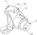
图1是本发明实施例中一种多功能翻修手术工具系统的立体图;1 is a perspective view of a multifunctional revision surgical tool system according to an embodiment of the present invention;
图2是本发明实施例中一种多功能翻修手术工具系统安装于股骨远端的示意图;2 is a schematic diagram of a multifunctional revision surgical tool system installed on the distal end of the femur according to an embodiment of the present invention;
图3是本发明实施例中柱件的立体图;3 is a perspective view of a column in an embodiment of the present invention;
图4是本发明实施例中柱筒件的立体图;4 is a perspective view of a cylindrical member in an embodiment of the present invention;
图5是本发明实施例中髁试模的立体图;Fig. 5 is the perspective view of the condyle try-out in the embodiment of the present invention;
图6是本发明实施例中髁试模的侧视图;Fig. 6 is the side view of condyle try-out in the embodiment of the present invention;
图7是本发明实施例中髁试模固定于股骨远端的示意图;7 is a schematic view of the condyle trial mold being fixed to the distal end of the femur in the embodiment of the present invention;
图8是本发明实施例中骨界面A处完成髁间截骨的示意图;8 is a schematic diagram of the completion of the intercondylar osteotomy at the bone interface A in the embodiment of the present invention;
图9是本发明实施例中髁间试模的立体图;Fig. 9 is the perspective view of the intercondylar try-out in the embodiment of the present invention;
图中:In the picture:
髁试模1,前髁段试模11,远端段试模12,后髁段试模13,髁间槽14,截骨槽15,第一截骨槽151,第二截骨槽152,螺纹孔16,固定孔17,凹陷台阶18,连接孔19;
柱筒件2,左通孔21,右通孔22,指示箭头23,方向标识24,第一挂耳25,左避让面26,右避让面27;
柱件3,力线通孔31,定位部32,手柄部33,缘凸34,刻度35;
螺钉4;
髁间试模5,髁间试模主体51,试模补充件52,第二挂耳53;The
力线杆6;force
固定钉7。Fixing pegs 7.
具体实施方式Detailed ways
下面将结合本发明实施例中的附图,对本发明实施例中的技术方案进行清楚、完整地描述,显然,所描述的实施例仅仅是本发明一部分实施例,而不是全部的实施例。基于本发明中的实施例,本领域普通技术人员在没有做出创造性劳动前提下所获得的所有其他实施例,都属于本发明保护的范围。The technical solutions in the embodiments of the present invention will be clearly and completely described below with reference to the accompanying drawings in the embodiments of the present invention. Obviously, the described embodiments are only a part of the embodiments of the present invention, but not all of the embodiments. Based on the embodiments of the present invention, all other embodiments obtained by those of ordinary skill in the art without creative efforts shall fall within the protection scope of the present invention.
在进行初次膝关节假体置换后,由于病患非预期受创或长时间使用,初次假体会发生送松动或骨质再次发生缺损,导致病患疼痛,进而再次丧失行走功能。这就需要将原有假体去除,重建骨界面,安装翻修假体,这个过程就是膝关节的翻修手术。在现有的膝关节翻修手术中,股骨侧的步骤是先重建骨界面,再将髁试模安装于重建的骨界面处,确认髁试模与股骨力线的关系以及髁试模与股骨远端的关系,最后卸下髁试模,安装髁假体。After the primary knee prosthesis replacement, due to the patient's unintended trauma or prolonged use, the primary prosthesis may become loose or the bone will be lost again, causing the patient to suffer pain and lose the ability to walk again. This requires the removal of the original prosthesis, the reconstruction of the bone interface, and the installation of a revision prosthesis. This process is called knee revision surgery. In the existing knee joint revision surgery, the steps on the femoral side are to reconstruct the bone interface first, and then install the condyle trial at the reconstructed bone interface to confirm the relationship between the condyle trial and the femoral force line and the distance between the condyle trial and the femur. Finally, remove the condyle try-out and install the condyle prosthesis.
然而该手术步骤导致了一定的缺陷:现有技术中医生需要先进行骨界面截骨,然后进行髁试模适配,当发现髁试模位置存在偏差时,就需要再次截骨,这样会导致假体安装位置不精准或增大截骨量,增加手术风险;再者,现有技术中是采用定位工具确定截骨与力线的关系,医生根据确定的数值调整力线杆与髁试模的相对安装位置,当力线杆与髁试模组装到一起放置到骨界面进行复位时,时常产生偏差,此时需要撤下力线杆与髁试模重新定位,这样也会增加手术风险。However, this surgical procedure leads to certain defects: in the prior art, doctors need to perform bone interface osteotomy first, and then perform condyle trial fitting. The installation position of the prosthesis is inaccurate or the amount of osteotomy increases, which increases the risk of surgery. Furthermore, in the prior art, positioning tools are used to determine the relationship between the osteotomy and the force line, and the doctor adjusts the force line rod and the condyle trial according to the determined value. When the force line rod and condyle trial mold are assembled together and placed on the bone interface for reduction, deviations often occur. At this time, the force line rod and condyle trial mold need to be removed and repositioned, which will also increase the risk of surgery. .
基于此,本申请考虑通过直接在髁试模上进行力线与髁试模相对位置的确认,并直接在髁试模上确认截骨位置的方式以解决现有技术中的问题,具体的,本申请提供实施例,具体为一种多功能翻修手术工具系统的最佳方案,用以配合新的手术方式,实现先安装髁试模、再重建骨界面,减小手术风险的技术效果。Based on this, the present application considers directly confirming the relative position of the force line and the condyle trial on the condyle trial, and directly confirming the osteotomy position on the condyle trial to solve the problems in the prior art. Specifically, The present application provides embodiments, specifically an optimal solution of a multifunctional revision surgical tool system, which is used to cooperate with a new surgical method to achieve the technical effect of first installing a condyle trial model, then reconstructing the bone interface, and reducing surgical risks.
具体的,如图1,本工具系统包括有髁试模1,髁试模1本体的形状结构与传统膝关节翻修手术技术中一致,髁试模1包括有髁间槽14和截骨槽15,当髁试模1安装于股骨远端时,髁间槽14暴露股骨远端的髁间位置;还包括有柱筒件2,柱筒件2包括有通孔,通孔的两端分别延伸至柱筒件2的两端端部,通孔的中轴线与柱筒件2的中轴线呈夹角,该夹角优选为股骨力线与股骨机械轴线之间的夹角,髁试模1与柱筒件2之间为可拆卸连接;还包括有柱件3,柱件3包括有力线通孔31,力线通孔31的两端分别延伸至柱件3的两端端部,力线通孔31位于柱件3的偏心位置,将柱件3置于通孔内,施加外力转动柱件3时,可调节柱筒件2与力线通孔31的相对位置;Specifically, as shown in Figure 1, the tool system includes a
如图2,进行膝关节翻修手术的股骨侧操作时,先去除病患原有的初次假体,将股骨侧的原始骨界面A暴露,于骨界面A的远端位置打入力线杆6,确定股骨的力线;接着将髁试模1置于骨界面A处,力线杆6穿过髁间槽14暴露于髁试模1外;再将柱筒件2安装于髁试模1上,使柱筒件2与髁试模1固定连接,同时使通孔与髁间槽14对应,力线杆6穿过通孔暴露于柱筒件2外;然后将柱件3置于通孔中,使力线杆6穿过力线通孔31,此时力线杆6与柱件3同轴,与通孔呈夹角,即此时髁试模1的安装力线得以保障,只需调整髁试模1与骨界面A的相对位置,使髁试模1与骨界面A实现最大程度的贴合即可,具体的,需要手动转动柱件3,由于置于力线通孔31中的力线杆6是固定的,力线通孔31位于柱件3的偏心位置,柱件3对柱筒件2的通孔具有干涉作用,所以柱件3会带动柱筒件2产生转动,从而带动髁试模1相对于骨界面A调整位置;最后卸下柱件3、柱筒件2,固定髁试模1后利用截骨刀于截骨槽15处进行截骨操作即可;As shown in Figure 2, when performing knee revision surgery on the femoral side, the original primary prosthesis of the patient is first removed, the original bone interface A on the femoral side is exposed, and the
如此先固定髁试模1再进行截骨的操作,可以避免测量误差,保障力线与手术规划一致,同时保障重建的骨界面与确定好的股骨髁翻修假体位置精准对应,使得手术更加流畅,手术操作时间减少,手术风险降低。In this way, the operation of fixing the
进一步的,柱件3的结构具体为:如图3,包括有定位部32,定位部32用于伸入通孔,定位部32优选为圆柱结构,且定位部32的外径与通孔的内径适应配合,使定位部32可以刚好置入通孔内;还包括有手柄部33,手柄部33与定位部32连接或一体成型,用于方便把持,在本实施例中,手柄部33优选也为圆柱结构,同时优选与定位部32一体成型;还包括有缘凸34,缘凸34与定位部32/手柄部33连接或一体成型,缘凸34用于对柱筒件2的端部形成挡止作用,防止柱件3在柱筒件2内轴向窜动,在本实施例中,缘凸34优选均与定位部32、手柄部33一体成型;其中力线通孔31一端延伸至定位部32的端部,另一端延伸至手柄部33的端部,即力线通孔31贯穿了柱件3。Further, the structure of the
进一步的,为了适应左右腿的应用场景,如图4,本工具系统设置了通孔包括有左通孔21与右通孔22,左通孔21的中轴线与右通孔22的中轴线均和柱筒件2的中轴线存在夹角,使柱筒件2可以通用在左右腿上,同时左通孔21与右通孔22相互交叠,其中相互交叠的左通孔21与右通孔22共用了空间,使柱筒件2的体积可以保持较小,如此可以减少手术工具,降低费用;Further, in order to adapt to the application scenarios of the left and right legs, as shown in Figure 4, the tool system is provided with a through hole including a left through
进一步的,由于柱件3置入柱筒件2后,二者之间具有夹角,想要柱件3与柱筒件2之间具有较为稳定的关系,缘凸34与柱筒件2的端部需要贴合,基于此,如图4,设置了柱筒件2包括有设置于其一端端部的左避让面26与右避让面27,左避让面26或右避让面27与缘凸34对应贴合,其中左通孔21延伸至左避让面26处,右通孔22延伸至右避让面27处。Further, after the
进一步的,如图3~4,为了记录髁试模1与力线杆6的相对位置,便于后续翻修假体的置入,设置了柱筒件2包括有指示箭头23,指示箭头23位于柱筒件2的外壁上,柱件3包括有刻度35,刻度35位于缘凸34上,刻度35与指示箭头23对应,用于指示髁试模1与力线的相对位置,其中优选的,指示箭头23包括有左指示箭头与右指示箭头,分别用于记录左右腿的情况。Further, as shown in Figures 3 to 4, in order to record the relative position of the
进一步的,如图4,柱筒件2还包括有方向标识24,方向标识24包括有用于指示左右方向的左方向标识与右方向标识,以方便医生操作。Further, as shown in FIG. 4, the
进一步的,柱筒件2与髁试模1的连接方式为:如图4~5,柱筒件2包括有第一挂耳25,第一挂耳25设置于柱筒件2外部,与柱筒件2连接或一体成型,优选的,第一挂耳25有两个,为一端收口的柱筒结构,与柱筒件2一体成型;髁试模1包括有螺纹孔16,螺纹孔16开设于髁试模1上,优选的,髁试模1上接近髁间槽14的两侧有凹陷台阶18,螺纹孔16有两个,分别开设于两个凹陷台阶18上;工具系统还包括有两个螺钉4,第一挂耳25与螺纹孔16之间通过螺钉4连接,其中螺钉4优选为沉头螺钉,将第一挂耳25与螺纹孔16连接时,螺钉4的头部沉入第一挂耳25内。Further, the connection mode of the
进一步的,如图5,髁试模1还包括有若干固定孔17,分别分布于前髁段试模11和/或远端段试模12上,用于置入固定钉7以固定髁试模1,优选的,前髁段试模11的边缘处分布有三个固定孔17,远端段试模12的边缘处分布有两个固定孔17,可将髁试模1稳定的连接于骨界面A上,如图7即表现了撤去柱筒件2和柱件3后,将髁试模1固定于骨界面A处的示意图。Further, as shown in Figure 5, the
进一步的,如图5,髁试模1包括有前髁段试模11、以及远端段试模12、以及后髁段试模13,前髁段试模11、远端段试模12、后髁段试模13三者之间一体成型。Further, as shown in Figure 5, the
进一步的,如图5~6,截骨槽15有若干个,分别分布于前髁段试模11和/或远端段试模12和/或后髁段试模13上,且每个截骨槽15延伸至与髁试模1的外缘连通,以方便锯刀入刀;优选的,前髁段试模11的内外侧均设置有两个第一截骨槽151,第一截骨槽115自前髁段试模11延伸至后髁段试模13上,用于对骨界面A的远端进行截骨,其中位于前髁段试模11同侧的第一截骨槽151均包括了5mm截骨槽和10mm截骨槽,即第一截骨槽151至远端段试模12的垂直距离为5mm或10mm,优选的,远端段试模12的内外侧均设置有两个第二截骨槽152,第二截骨槽152用于对骨界面A的后髁进行截骨,其中位于远端段试模12同侧的第二截骨槽152均包括了5mm截骨槽和10mm截骨槽,即第二截骨槽152至后髁段试模13的垂直距离为5mm或10mm,截骨过程中,可以根据骨缺损情况,选择不同的截骨槽15来重建骨界面。Further, as shown in Figures 5 to 6, there are
进一步的,髁间槽14也可以作为截骨引导槽,沿着髁间槽14的内壁进行髁间截骨,从而固定下来翻修假体最终的安放位置;沿着髁间槽14进行截骨时,由于髁间槽14接近前髁段试模11处的侧壁较薄,不能对锯刀形成很好的导向作用,因此如图5,设置了髁试模1还包括有连接孔19,连接孔19具体包括有一个腰型通孔和位于腰型通孔两侧的圆通孔,连接孔19用于与导向块上的柱件连接,使导向块连接于髁试模1上,如此可沿着导向块进行髁间截骨,对锯刀形成导向作用,如图8即表现了骨界面A处完成了髁间截骨的示意图。Further, the
进一步的,为了复原出整体的翻修股骨髁假体外形,使后续翻修股骨髁假体的安装顺利,如图9,本工具系统还包括与髁间试模5,其中髁间试模5具体包括有髁间试模主体51,髁间试模主体51为柱状结构,为植入骨质的部分;还包括有试模补充件52,试模补充件52与髁间槽14对应贴合,试模补充件52与髁间试模主体51一体成型,试模补充件52与髁试模1可拼接出完整的翻修股骨髁假体外形。Further, in order to restore the overall shape of the revision femoral condyle prosthesis, so that the installation of the subsequent revision femoral condyle prosthesis is smooth, as shown in Figure 9, the tool system also includes and the
进一步的,髁间试模5与髁试模1的连接方式为:如图5、9,髁间试模5包括有第二挂耳53,第二挂耳53与螺纹孔16对应,第二挂耳53与螺纹孔16之间也通过螺钉4连接,其中凹陷台阶18与第二挂耳53对应贴合,使髁间试模5与髁试模1的拼接完整平滑。Further, the connection mode of the
需要说明的是,在本文中,诸如第一和第二等之类的关系术语仅仅用来将一个实体或者操作与另一个实体或操作区分开来,而不一定要求或者暗示这些实体或操作之间存在任何这种实际的关系或者顺序。而且,术语“包括”、“包含”或者其任何其他变体意在涵盖非排他性的包含,从而使得包括一系列要素的过程、方法、物品或者设备不仅包括那些要素,而且还包括没有明确列出的其他要素,或者是还包括为这种过程、方法、物品或者设备所固有的要素。It should be noted that, in this document, relational terms such as first and second are only used to distinguish one entity or operation from another entity or operation, and do not necessarily require or imply any relationship between these entities or operations. any such actual relationship or sequence exists. Moreover, the terms "comprising", "comprising" or any other variation thereof are intended to encompass a non-exclusive inclusion such that a process, method, article or device that includes a list of elements includes not only those elements, but also includes not explicitly listed or other elements inherent to such a process, method, article or apparatus.
最后应说明的是:以上所述仅为本发明的优选实施例而已,并不用于限制本发明,尽管参照前述实施例对本发明进行了详细的说明,对于本领域的技术人员来说,其依然可以对前述各实施例所记载的技术方案进行修改,或者对其中部分技术特征进行等同替换。凡在本发明的精神和原则之内,所作的任何修改、等同替换、改进等,均应包含在本发明的保护范围之内。Finally, it should be noted that the above descriptions are only preferred embodiments of the present invention, and are not intended to limit the present invention. Although the present invention has been described in detail with reference to the foregoing embodiments, for those skilled in the art, the The technical solutions described in the foregoing embodiments may be modified, or some technical features thereof may be equivalently replaced. Any modification, equivalent replacement, improvement, etc. made within the spirit and principle of the present invention shall be included within the protection scope of the present invention.
Claims (10)
Priority Applications (1)
| Application Number | Priority Date | Filing Date | Title |
|---|---|---|---|
| CN202210774876.6A CN114948356A (en) | 2022-07-01 | 2022-07-01 | A multifunctional revision surgical tool system |
Applications Claiming Priority (1)
| Application Number | Priority Date | Filing Date | Title |
|---|---|---|---|
| CN202210774876.6A CN114948356A (en) | 2022-07-01 | 2022-07-01 | A multifunctional revision surgical tool system |
Publications (1)
| Publication Number | Publication Date |
|---|---|
| CN114948356A true CN114948356A (en) | 2022-08-30 |
Family
ID=82967060
Family Applications (1)
| Application Number | Title | Priority Date | Filing Date |
|---|---|---|---|
| CN202210774876.6A Pending CN114948356A (en) | 2022-07-01 | 2022-07-01 | A multifunctional revision surgical tool system |
Country Status (1)
| Country | Link |
|---|---|
| CN (1) | CN114948356A (en) |
Citations (8)
| Publication number | Priority date | Publication date | Assignee | Title |
|---|---|---|---|---|
| CN104546088A (en) * | 2015-01-07 | 2015-04-29 | 北京爱康宜诚医疗器材股份有限公司 | Customized compound bone cutter for femoral condyle |
| CN207640466U (en) * | 2017-05-19 | 2018-07-24 | 上海博玛医疗科技有限公司 | A kind of distal femur osteotomy modular device |
| CN109077833A (en) * | 2018-09-29 | 2018-12-25 | 北京爱康宜诚医疗器材有限公司 | Lateral femoral condyle prosthesis component |
| CN110801264A (en) * | 2019-11-14 | 2020-02-18 | 北京市春立正达医疗器械股份有限公司 | Intercondylar osteotomy module |
| CN111035483A (en) * | 2019-12-30 | 2020-04-21 | 北京爱康宜诚医疗器材有限公司 | Surgical tool |
| CN210472337U (en) * | 2019-04-04 | 2020-05-08 | 经纬医疗器材制造(深圳)有限公司 | Knee joint femoral prosthesis test mould with intercondylar osteotomy slot |
| CN111759397A (en) * | 2020-06-28 | 2020-10-13 | 北京力达康科技有限公司 | Distal bone defect of femoral condyle cuts bone locator |
| CN113397651A (en) * | 2021-07-21 | 2021-09-17 | 袁海浪 | Method for positioning longitudinal tibial osteotomy position in unicondylar replacement |
-
2022
- 2022-07-01 CN CN202210774876.6A patent/CN114948356A/en active Pending
Patent Citations (8)
| Publication number | Priority date | Publication date | Assignee | Title |
|---|---|---|---|---|
| CN104546088A (en) * | 2015-01-07 | 2015-04-29 | 北京爱康宜诚医疗器材股份有限公司 | Customized compound bone cutter for femoral condyle |
| CN207640466U (en) * | 2017-05-19 | 2018-07-24 | 上海博玛医疗科技有限公司 | A kind of distal femur osteotomy modular device |
| CN109077833A (en) * | 2018-09-29 | 2018-12-25 | 北京爱康宜诚医疗器材有限公司 | Lateral femoral condyle prosthesis component |
| CN210472337U (en) * | 2019-04-04 | 2020-05-08 | 经纬医疗器材制造(深圳)有限公司 | Knee joint femoral prosthesis test mould with intercondylar osteotomy slot |
| CN110801264A (en) * | 2019-11-14 | 2020-02-18 | 北京市春立正达医疗器械股份有限公司 | Intercondylar osteotomy module |
| CN111035483A (en) * | 2019-12-30 | 2020-04-21 | 北京爱康宜诚医疗器材有限公司 | Surgical tool |
| CN111759397A (en) * | 2020-06-28 | 2020-10-13 | 北京力达康科技有限公司 | Distal bone defect of femoral condyle cuts bone locator |
| CN113397651A (en) * | 2021-07-21 | 2021-09-17 | 袁海浪 | Method for positioning longitudinal tibial osteotomy position in unicondylar replacement |
Similar Documents
| Publication | Publication Date | Title |
|---|---|---|
| US20230293192A1 (en) | Patient-specific template for total ankle replacement | |
| US5702460A (en) | Revision femoral trial prosthesis | |
| EP2445419B1 (en) | A positioning guide and a femur bone cutting guide system | |
| US9138241B2 (en) | Methods and apparatus for preparing a patient's femur for patellofemoral knee arthroplasty | |
| US5258032A (en) | Knee prosthesis provisional apparatus and resection guide and method of use in knee replacement surgery | |
| US10463379B2 (en) | Customized surgical cutting guide for total knee replacement and method for making thereof | |
| US6187010B1 (en) | Bone cutting guides for use in the implantation of prosthetic joint components | |
| CN108309393B (en) | Patient-specific devices and methods for joint repair | |
| PT809471E (en) | Distal femoral cutting guide | |
| BR112018073530B1 (en) | ORTHOPEDIC SURGICAL INSTRUMENT SYSTEM | |
| CN114948356A (en) | A multifunctional revision surgical tool system | |
| CN107348987B (en) | A personalized distal femoral osteotomy guide plate for knee joint replacement surgery and its realization method | |
| CN216985304U (en) | A pre-cut bone trial in joint replacement surgery | |
| CN107595443B (en) | Split femoral condyle prosthesis and artificial knee joint | |
| CN215960126U (en) | Angle-adjustable single-condyle replacement femoral punching device | |
| CN114681003A (en) | Elbow-varus-outer-side closed wedge-shaped osteotomy guide plate and manufacturing method thereof | |
| CN113813007A (en) | Angle-adjustable femoral punching device | |
| KR102136741B1 (en) | Patient Specific Surgical Instrument to Guide Position of Cutting Block | |
| CN207168541U (en) | Distal femur osteotomy positioning guide device | |
| RU2800885C2 (en) | Surgical guide for zygomatic implants | |
| JP2023521910A (en) | Tibial Osteotomy Systems, Instruments, and Related Methods | |
| US20240016611A1 (en) | Device and method to assist revision surgeries for knee arthroplasty | |
| CN213940877U (en) | Knee joint osteotomy tool | |
| KR20240120360A (en) | Patient Specific Surgical Instrument that is Precisely Placed in a Pre-Planned Position Through Point Contact | |
| CN119033438A (en) | Tibia force line positioning tool for total knee arthroplasty |
Legal Events
| Date | Code | Title | Description |
|---|---|---|---|
| PB01 | Publication | ||
| PB01 | Publication | ||
| SE01 | Entry into force of request for substantive examination | ||
| SE01 | Entry into force of request for substantive examination |