CN114930962A - Resource allocation signaling in wireless local area network preamble - Google Patents
Resource allocation signaling in wireless local area network preamble Download PDFInfo
- Publication number
- CN114930962A CN114930962A CN202080092353.2A CN202080092353A CN114930962A CN 114930962 A CN114930962 A CN 114930962A CN 202080092353 A CN202080092353 A CN 202080092353A CN 114930962 A CN114930962 A CN 114930962A
- Authority
- CN
- China
- Prior art keywords
- mru
- field
- sig
- user
- rus
- Prior art date
- Legal status (The legal status is an assumption and is not a legal conclusion. Google has not performed a legal analysis and makes no representation as to the accuracy of the status listed.)
- Pending
Links
Images


Classifications
-
- H—ELECTRICITY
- H04—ELECTRIC COMMUNICATION TECHNIQUE
- H04L—TRANSMISSION OF DIGITAL INFORMATION, e.g. TELEGRAPHIC COMMUNICATION
- H04L5/00—Arrangements affording multiple use of the transmission path
- H04L5/003—Arrangements for allocating sub-channels of the transmission path
- H04L5/0053—Allocation of signalling, i.e. of overhead other than pilot signals
-
- H—ELECTRICITY
- H04—ELECTRIC COMMUNICATION TECHNIQUE
- H04L—TRANSMISSION OF DIGITAL INFORMATION, e.g. TELEGRAPHIC COMMUNICATION
- H04L5/00—Arrangements affording multiple use of the transmission path
- H04L5/003—Arrangements for allocating sub-channels of the transmission path
- H04L5/0037—Inter-user or inter-terminal allocation
-
- H—ELECTRICITY
- H04—ELECTRIC COMMUNICATION TECHNIQUE
- H04W—WIRELESS COMMUNICATION NETWORKS
- H04W72/00—Local resource management
- H04W72/04—Wireless resource allocation
- H04W72/044—Wireless resource allocation based on the type of the allocated resource
- H04W72/0453—Resources in frequency domain, e.g. a carrier in FDMA
-
- H—ELECTRICITY
- H04—ELECTRIC COMMUNICATION TECHNIQUE
- H04W—WIRELESS COMMUNICATION NETWORKS
- H04W72/00—Local resource management
- H04W72/20—Control channels or signalling for resource management
- H04W72/23—Control channels or signalling for resource management in the downlink direction of a wireless link, i.e. towards a terminal
-
- H—ELECTRICITY
- H04—ELECTRIC COMMUNICATION TECHNIQUE
- H04W—WIRELESS COMMUNICATION NETWORKS
- H04W84/00—Network topologies
- H04W84/02—Hierarchically pre-organised networks, e.g. paging networks, cellular networks, WLAN [Wireless Local Area Network] or WLL [Wireless Local Loop]
- H04W84/10—Small scale networks; Flat hierarchical networks
- H04W84/12—WLAN [Wireless Local Area Networks]
Landscapes
- Engineering & Computer Science (AREA)
- Signal Processing (AREA)
- Computer Networks & Wireless Communication (AREA)
- Mobile Radio Communication Systems (AREA)
- Time-Division Multiplex Systems (AREA)
- Cable Transmission Systems, Equalization Of Radio And Reduction Of Echo (AREA)
- Small-Scale Networks (AREA)
Abstract
An apparatus for wireless communication, comprising: a memory storing instructions; a processor coupled to the memory, wherein the processor and the memory are configured to: generating a signaling field (SIG) in a Wireless Local Area Network (WLAN), the SIG including a Resource Unit (RU) allocation field indicating a size and a location of each RU in frequency resources, the SIG further including one or more user fields, each user field including information of a scheduling Station (STA); wherein the MRU including a plurality of RUs is allowed to be allocated to one STA; the SIG is transmitted.
Description
Technical Field
The present invention relates to wireless communications, and more particularly, to a new method and apparatus for resource allocation signaling in a WLAN.
Background
In the IEEE 802.11ax standard, OFDMA modulation was introduced for the first time. The description of the RU for a given PPDU is given in its SIG-B field (and as shown in fig. 1, defined in detail in the 802.11ax standard). This field consists of 2 main subfields: common fields and user specific fields as described in the 802.11ax standard.
The above 802.11ax standard restricts each non-AP STA to use a single Resource Unit (RU) consisting of consecutive tones. Although various RU sizes are defined in the standard (e.g., 26 tones, 52 tones, 106 tones, 242 tones, 484 tones, 996 tones), restricting the allocation of a single RU limits the use of channel resources.
As mentioned above, in the current 802.11ax standard (i.e., prior art), there are 6RU sizes. In the allocation procedure, the scheduler may allocate only a single RU to a given STA in a multi-user phy protocol data unit (MU-PPDU) (transmitted packet) or single-user PPDU (SU-PPDU) transmission.
If there is an unallocated RU, the RU cannot be allocated to an STA to which an RU has been allocated.
Disclosure of Invention
The present invention is directed to extending and improving methods of using channel resources in a WLAN.
Methods, apparatus, and computer readable media for resource allocation signaling in a very high throughput Wireless Local Area Network (WLAN) are disclosed.
An apparatus such as an Access Point (AP) may generate a signaling field (SIG). The SIG includes a Resource Unit (RU) allocation field indicating a size and a position of each RU in the frequency resources. The SIG further includes one or more user fields, each user field including information of a scheduling Station (STA); wherein the allocation of an MRU comprising Multiple RUs (MRU) to one or more STAs (same) is allowed. The RU includes the RU defined in 802.11 ax. The MRU may be a small MRU comprising a combination of 26-RU, 52-RU, or 106-RU in the 20MHz band; or may be a large MRU comprising a combination of 242-RU, 484-RU, or 996-RU in the transmission bandwidth.
In some examples, the MRU includes a first RU and a second RU. The apparatus may generate a first user field corresponding to a first RU and a second user field corresponding to a second RU. The first user field and the second user field each include the same ID of the STA. The second user field may also include one or any combination of the following: the number of RUs allocated to the STA; or the size and location of each RU in the MRU allocated to the STA.
Alternatively, the apparatus may generate a common field of the SIG including information of the allocated small MRUs in the corresponding 20MHz band; and/or the number of large MRUs allocated in the transmission bandwidth.
Alternatively, the apparatus may generate a single RU user field and an MRU user field. The single RU user field corresponds to an RU that is not an MRU. The MRU user field corresponds to the MRU, which includes at least: STA _ ID, RU bitmap indicating the size and position of each RU included in the MRU.
Alternatively, the apparatus may generate a common MRU field indicating which 26-RUs are included in the MRU in the corresponding 20MHz band; and/or a common MRU field indicating which 242-RUs are included in the MRUs in the transmission bandwidth.
Alternatively, the apparatus may generate one or more common MRU fields, each common MRU field indicating whether (which) actually allocated RUs are in the MRU.
In addition, other information (e.g., channel puncturing information in the U-SIG) may be used to indicate MRU allocation. The puncturing information indicates a non-consecutive large RU and one or more user fields corresponding to the non-consecutive large RU, wherein each of the one or more user fields includes information of a different station.
One or more stations (e.g., wireless devices or mobile devices) may receive a WLAN preamble including SIG. Then, one or more stations may determine, based on the SIG, an MRU including a plurality of RUs allocated to the STA. Then, the station may determine the MRU allocated to the STA by:
a first user field corresponding to a first RU and a second user field corresponding to a second RU; the first user field and the second user field both comprise the same ID of the STA; the second user field may also include one or any combination of the following: the number of RUs allocated to the STA; or, the size and location of each RU in the MRU allocated to the STA; or
A common field of SIGs including information of small MRUs allocated in a corresponding 20MHz band; and/or the number of large MRUs allocated in the transmission bandwidth, or
A single RU user field and an MRU user field; the single RU user field corresponds to an RU that is not an MRU; the MRU user field corresponds to an MRU, which includes at least: a STA _ ID and an RU bitmap indicating a size and a position of each RU included in the MRU; or alternatively
A common MRU field indicating which 26-RUs to include in the MRU in the corresponding 20MHz band; and/or a common MRU field indicating which 242-RUs are included in the MRU in the transmission bandwidth; or
One or more common MRU fields, each common MRU field indicating whether (which) actually allocated RUs are in the MRU; or
Other information (e.g., puncturing information) indicating a non-consecutive large RU and one or more user fields corresponding to the non-consecutive large RU, each of the one or more user fields including information of a different station.
The above-described fields in the SIG may be load balanced in two or more channel contents. The mapping between MRUs (RUs, if present) and STAs is indicated by the structure of the fields and the location of the fields in the SIG.
Methods performed by the above-described apparatus (including an AP and a station) are also provided, as are computer-readable media for resource allocation signaling.
Some examples of the methods, apparatus, or non-transitory computer-readable media described herein may also include processes, features, approaches, or instructions for resource allocation signaling in a very high throughput WLAN preamble. Further scope of applicability of the described systems, methods, apparatus, or computer-readable media will become apparent from the following detailed description, claims, and drawings. The detailed description and specific examples are intended for purposes of illustration only, as various changes and modifications within the described scope will become apparent to those skilled in the art.
Drawings
The above and other objects and features of the present invention will become apparent from the following description of the preferred embodiments given in conjunction with the accompanying drawings, in which:
fig. 1 is a diagram showing a SIG-B field (defined in detail in the 802.11ax standard);
fig. 2 is a diagram showing an example of a wireless local area network;
fig. 3 is a flowchart showing how scheduling information in a WLAN is transmitted on the transmitting side;
fig. 4 is a flow chart showing how scheduling information in a WLAN is transmitted at a receiving side;
fig. 5 is a diagram showing an example of an indicating structure of embodiment 1;
fig. 6 is a diagram showing another example of resource allocation in the embodiment;
fig. 7 is a diagram showing another example of an indicating structure in the embodiment;
fig. 8 is a diagram showing another example of an indicating structure in the embodiment;
fig. 9a, 9b, 9c are diagrams illustrating examples of common fields of EHT-SIG;
FIG. 10a is a diagram illustrating an example of a resource allocation and scheduling station on an RU;
fig. 10b is a diagram illustrating an example of a structure of a common field of an EHT-SIG indicating the resource allocation of fig. 10 a;
fig. 11a is a diagram showing an example of the structure of a user-specific field of an EHT-SIG in the embodiment;
fig. 11b is a diagram showing an example of the structure of an MRU user field in a user-specific field of an EHT-SIG;
fig. 12a and 12b are diagrams illustrating a structure of a user field in a user-specific field of an EHT-SIG;
FIG. 13 is a diagram showing a simulation result;
fig. 14 is a diagram showing another example of an indication structure of a common MRU;
fig. 15 is a diagram showing an example of resource allocation and UR mapping in the embodiment;
fig. 16 is a diagram showing an example of resource allocation and UR mapping in the embodiment;
fig. 17a is a diagram showing another example of resource allocation in the embodiment;
FIG. 17b is a diagram showing an indication structure of resource allocation in FIG. 17 a;
FIG. 17c is a diagram showing another indication structure of resource allocation in FIG. 17 a;
fig. 18 is a diagram showing another example of resource allocation and its indication structure;
fig. 19 is a diagram showing an example of a transmission containing a hybrid MRU;
fig. 20 is a diagram showing another example of resource allocation in the embodiment;
fig. 21 is a block diagram of an access point according to an embodiment of the present invention; and
fig. 22 is a block diagram of a station according to an embodiment of the present invention.
Detailed Description
Hereinafter, a method of using channel resources in 802.11be by allowing STAs to use a plurality of discontinuous portions of a channel according to an embodiment of the present invention will be explained with reference to the accompanying drawings.
For ease of understanding, the terms that may appear in the following examples are explained as follows:
AP access point
AT access terminal
BSS basic service set
BW bandwidth
CC content channel
DL downlink
DS distribution system
EHT extreme high throughput
ESS extended service set
HE high efficiency of efficiency
LLC local link control logical link control
L-LTF Non-HT Long Training field
L-SIG Non-HT SIGNAL field
L-STF Non-HT Short Training field
LTF long training field
MAC medium access protocol
MCS modulation and coding scheme
MLD multi-link device
MRU multiple resource units
MS mobile station
MU multi-user
MU-MIMO multi-user multi-input, multi-output multi-user MIMO
NDP null data PPDU
OFDM orthogonal frequency division multiplexing
OFDMA Orthogonal Frequency Division Multiple Access (OFDMA) orthogonal frequency domain division multiple access (OFDMA OFDM) method
PHY physical layer
PPDU PHY protocol data unit physical layer protocol data unit
RA RU allocation field Allocation field
RL-SIG reproduced Non-HT SIGNAL field Repeated Non-HT SIGNAL field
RU resource unit
SAP service access point
SS subscriber station
STA station
SU single user
TDLS (time-dependent logic link setup) channel direct link setup
TID traffic identifier
TXOP transmission opportunity
UE User Equipment (UE) user equipment (UE user equipment)
UL Uplink
U-SIG Universal Signal field
WM wireless media
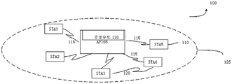
Fig. 2 illustrates an example of a Wireless Local Area Network (WLAN)100, the WLAN 100 supporting resource allocation signaling or scheduling signaling in a WLAN preamble (e.g., EHT WLAN preamble), in accordance with various aspects of the present disclosure.
Although not shown in fig. 2, STA 110 may be covered by multiple APs 105 and may therefore associate with multiple APs 105 at different times. The set of a single AP 105 and associated STAs 110 is referred to as a Basic Service Set (BSS). An Extended Service Set (ESS) is a set of connected BSSs. A Distribution System (DS) is used to connect the APs 105 in the extended service set. The coverage area 125 of an AP 105 may be divided into sectors that form only a portion of the coverage area. The WLAN 100 includes APs 105 of different types (e.g., metropolitan area, home network, etc.) that have different sizes of coverage areas and overlapping coverage areas for different technologies. Although not shown, other devices may communicate with the AP 105.
While STAs 110 are able to communicate with each other through AP 105 using communication link 115, STAs 110 may also communicate directly with each other via direct wireless communication link 120. A direct wireless communication link may exist between STAs 110 regardless of whether any of STAs 110 are connected to AP 105. Examples of direct wireless communication links 120 include Wi-Fi direct connections, connections established using a Wi-Fi channel direct link setup (TDLS) link, and other peer-to-peer (P2P) group connections.
Transmissions to/from STA 110 and AP 105 typically include Uplink (UL) transmissions or Downlink (DL) transmissions. In the downlink transmission, control information within a header is transmitted prior to data transmission. The information provided in the header is used by the device to decode subsequent data. The very high throughput WLAN preamble may be used to schedule multiple devices (e.g., STAs 110) for single-user simultaneous transmission (e.g., single-user orthogonal frequency division multiple access (SU OFDMA)) and/or MU-MIMO transmission. In one example, the EHT WLAN signaling field may be used to signal a resource allocation pattern to a plurality of receiving STAs 110. The EHT WLAN signaling field includes a common field that is decodable by the plurality of STAs 110, the common field including a resource allocation field. The resource allocation field indicates resource unit allocations to the plurality of STAs 110 and indicates which resource units in the resource unit allocations correspond to MU-MIMO transmissions and which resource units correspond to OFDMA single-user transmissions. Following the common field, the EHT WLAN signaling field also includes a dedicated user field assigned to the particular STA 110. The order in which the dedicated user fields are generated corresponds to the order in which the resource units are allocated (e.g., the first dedicated user field corresponds to the first allocated resource unit). The EHT WLAN signaling field is transmitted to the plurality of STAs 110 along with the WLAN preamble.
It is not limited that some of the above embodiments may be used for uplink transmission, i.e. some of the above features or solutions are used in the trigger for triggering uplink transmission.
As shown in fig. 3, an embodiment includes a method of transmitting scheduling information in a WLAN:
101. an apparatus, such as an access point, generates a SIG (such as an EHT-SIG) that includes indication information or scheduling information. The above "generation" may be replaced by "construction", "acquisition", or "determination".
102. The apparatus transmits SIG.
Accordingly, another embodiment includes a method of receiving scheduling information in a WLAN at a non-AP station, as shown in fig. 4.
201. And receiving a PPDU, wherein SIG (such as EHT-SIG) is included in the PPDU. The SIG can take the structure discussed in the examples below. PPDUs may include L-STF, L-LTF, L-SIG, RL-SIG, U-SIG, and EHT-SIG.
In the EHT preamble, there may be one 2OFDM symbol long, jointly coded U-SIG immediately following the RL-SIG. The U-SIG contains a version independent field. The purpose of the version independent content is to achieve better coexistence between future 802.11 generations. In addition, the U-SIG may have some version-related fields. The U-SIG is transmitted using 52 data tones and 4 pilot tones per 20 MHz. In an EHT PPDU transmitted to a plurality of users, there may be a variable Modulation and Coding Scheme (MCS) and a variable length EHT-SIG immediately after the U-SIG.
202. The SIG is processed. Specifically, scheduling information is obtained based on the SIG.
EHT-SIG is the name of a field to distinguish it from other SIG-Bs, such as VHT-SIG-B, HE-SIG-B. EHT-SIG may be renamed in other ways; that is, the name itself is not important, but the content and structure discussed and described in the following embodiments provide a solution for efficient scheduling of resources and stations.
First, in an embodiment, through the EHT-SIG, a Resource Unit (RU) allocation field indicates at least an RU sequence in a frequency domain (size and position of each RU), and may also indicate information required to calculate the number of users allocated to each RU. The EHT-SIG further includes one or more user fields, each user field including information of a scheduling Station (STA); among other things, multiple consecutive RUs or non-consecutive RUs (which may be referred to as MRUs or MRUs) defined in 802.11ax are allowed to be allocated to one or more STAs. As used herein, "MRU" generally refers to an RU consisting of multiple consecutive RUs or non-consecutive RUs, such as defined in 802.11 ax. These RUs can be considered as the newly defined RUs in the next generation 802.11ax (e.g., 802.11 be).
In contrast to 802.11ax, each RU allocation subfield in the EHT-SIG content channel corresponding to the 20MHz frequency band indicates the RU allocation (including the size of the RU and its location in the frequency domain and one or more combinations of multiple RUs to be used in the EHT modulation field of the EHT MU PPDU in the frequency domain), and may also indicate the information needed to calculate the number of users allocated to each RU (non-MRU) and each combination of Multiple RUs (MRU). In a preferred embodiment, the subcarrier index of an RU satisfies the conditions in the table that may be defined in the 802.11be standard (an RU is associated with each RU allocation subfield for each EHT SIG content channel and PPDU bandwidth).
One or more STAs may be assigned to the same MRU or 802.11ax RU (non-MRU) in MU-MIMO format. This means that the partial RA subfield content will define the number of STAs, similar to the definition of 802.11 ax: 242-RU, 484-RU, and 996-RU are defined by 11000y2y1y0, 11001y2y1y0, and 11010y2y1y0, respectively. However, in 802.11be, a maximum of 16 STAs per RU may be supported, and thus the above-described embodiment may include an RU allocation field (RA) having a value greater than 8 bits (e.g., 9 bits or 10 bits) to support indicating the number of stations.
For example: 11000y3y2y1y0 indicates 242-RU, y3y2y1y0 indicates the number of stations on 242-RU, the number of stations is equal to y3y2y1y0+ 1;
11001y2y1y0 indicates 484-RU, y3y2y1y0 indicates the number of stations on 484-RU, the number of stations is equal to y3y2y1y0+ 1;
11010y3y2y1y0 indicates 996-RU, y3y2y1y0 indicates the number of stations on 996-RU, which is equal to y3y2y1y0+ 1.
The following embodiments omit the difference in RA between 802.11ax, if present, to make the solution of the embodiment or example concise. That is, the value of RA used in the following embodiments/examples may be replaced by a new value corresponding to 802.11 be. In some embodiments, the number of RUs that can be combined into an MRU is limited. That is, limited MRUs may be defined, each MRU representing the size and location of a plurality of subcarriers in a bandwidth that overlaps with a plurality of 802.11ax defined RUs.
Based on the RUs defined in 802.11ax (e.g., small RUs: 26,52, or 106), some examples of MRUs (combinations) include: MRUs including 52,26 or 106,26 in a 20MHz, 40MHz, or 80MHz band. In some examples, only a combination of consecutive small-sized RUs should be introduced, and in some examples, non-consecutive configurations are also allowed. For a large RU: 242. 484, or 996, some reasonably preferred MRUs (combinations) include:
1.242 +484 (continuous and discontinuous, within each 80MHz segment);
2.242 +242 (case of punching, non-continuous);
3. 484+996;
4. 242+484+242+484;
5. 242+484+996;
6.242 +242+996 and the like
Furthermore, based on some predefined MRUs (i.e. a combination of RUs defined by 802.11ax, which may also be referred to as MRUs), an important issue is to provide an efficient indication solution to indicate the allocation of MRUs and corresponding information of scheduling stations on MRUs. In other words, the problem is how to indicate the allocation of a plurality of RUs to a station and the information of the station and, correspondingly, how the station obtains the information of whether the station is scheduled and on which RU or MRU the station is allocated, in order for the station to communicate on the allocated RU or MRU, respectively.
Further, the AP decides RU allocation according to various criteria. For example, the AP may decide to use the RU with the highest SNR for a particular user, and these RUs are not necessarily consecutive. Further, all RUs in a transmission may contain the same data packet for one station, and all RUs in an MRU and other RUs in a PPDU are for the same type of service.
Specifically, in some embodiments, a single FEC with the same parameters (e.g., MCS, coding, N _ SS, etc.) may be allocated to the MRU-allocated STAs.
The small RU and the large RU described above may not be allocated to the same MRU allocation or it is not recommended to allocate one MRU including the small RU and the large RU. In a preferred embodiment, the small RUs may not be allocated across multiple 20MHz channels. Briefly, the MRU includes a combination of 26-RU, 52-RU, or 106-RU in the 20MHz band; alternatively, the MRU includes a combination of 242-RU, 484-RU, or 996-RU in the transmission bandwidth. But the MRU may not include one of the 26-RU, 52-RU, and 106-RU in the first 20MHz and one of the 242-RU, 484-RU, or 996-RU that overlaps with another 20 MHz.
Some embodiments may have some exceptions, i.e., a particular small RU in a first 20MHz channel may be combined with an RU in another 20MHz channel.
In some embodiments, MRUs that are not restricted to small RUs include only consecutive RUs. This may enable the scheduler to allocate RUs based on SNR (e.g., CQI feedback), allowing any combination of MRUs to be efficient.
This is not limited to a combination of small RUs.
Suppose RMS delay spread is E.E.E 1 / 3 If CP is-1 μ sec, the coherence BW is-1 MHz. Thus, the average SNR on a given RU does not mean the average SNR on its consecutive RUs.
In an embodiment, channel utilization is improved based on supporting multiple RU/non-consecutive RUs, since channel utilization is made more efficient by enhancing the ability to utilize channel selectivity. In addition, the use of the channel is improved and the throughput and performance of the overall system will be improved.
Example 1
The EHT-SIG in this embodiment differs from HE-SIG B specified in 802.11ax as follows:
allowing corresponding multiple user fields to point to the same STA. The common portion is included in the EHT-SIG and is similar in structure to the common portion of the HE-SIG B. However, a plurality of user fields of one STA are included in the user-specific field of the EHT-SIG. For example, a first user field is followed by other replicated second user fields. Briefly, the MRU includes a first RU and a second RU. Thus, the EHT-SIG includes a first user field corresponding to the first RU and a second user field corresponding to the second RU. The first user field and the second user field each include the same ID of the station.
The first user field may be similar to the user field defined in 802.11ax, but for other duplicated user fields (denoted as second user field or duplicated second user field) different solutions exist.
In particular, in one example, the replicated second user field is the same as the first user field. This example overcomes the prejudice specified in 802.11ax that only one user field/station is mapped to one RU and is therefore cost effective when designing new chips.
In another example, the duplicated second user field includes a STA _ ID field and other sub-fields that carry new signaling content related to the MRU. This solution supports MRU STAs in an easier way than the first example.
In the above example, the sizes of the plurality of user fields may be the same as each other, for example, 21, 22, or 23 bits. The first user field may be the same/similar (substantially identical in content or structure) as the 802.11ax user field.
Typically, the location of the combined second RU (corresponding to the copied user field) is not restricted; but in some examples, the rules for the location of the combined second RU/duplicate user field are set to reduce interference or inefficiency.
The content of the other user fields may be one of:
example 1, remain the same as the first user field;
example 2, comprising different content than the first user field, such that:
the first 11 bits are for the STA _ ID, as is the first user field.
Some of the other bits (e.g., 1 bit or 2 bits) are used to signal the type of user field (i.e., the meaning of the following bits).
The remaining bits may have any combination of the following new contents related to the MRU:
the 2 bits indicate N _ RU — the number of RUs allocated to the STA (including the first RU), or how many RUs are included in the MRU allocated to the STA. Thus, the STA may be able to identify the failure to decode any user field and stop the decoding process. The other 8 bits are reserved; or
Indicating the size and location of each RU in the MRU allocated to the STA. For example, by:
for small RUs: a 9-bit bitmap may indicate which 26-tones RUs in the same 20MHz channel (26-tones RUs) are part of the MRU allocation. 52-tonesRU can be indicated by an appropriate 2 bit; 106-tonesRU can be indicated by an appropriate 4-bit. The 10 th bit is reserved.
For a large RU: an 8-bit bitmap may indicate which 242-tonesRU's are part of the MRU allocation in the same 80MHz channel and the next 80MHz channel. 484-tonesRU (2 × 242-tonesRU) can be indicated by 2 bits; 996-tonesRU (4X 242-tonesRU) can be indicated by 4 bits. The 9 th and 10 th bits are reserved. In this embodiment, the MRU is limited to 160MHz boundaries. The STA may know whether to allocate an MRU to the STA after completing decoding of the EHT-SIG. Therefore, no special signaling is required for the MRU user field.
Fig. 5 shows an example of the indicating structure of embodiment 1. The RU Allocation (RA) field in the common portion of the EHT-SIG is set to "00000100", which represents the allocation of the RU sequence [26,26,52, middle 26,26,26,26,26 ]. Therefore, in the corresponding user-specific field, 8 User Fields (UF) are included. In this example, UF1 maps with the first 26-RU, including information for STA1, e.g., the AID for STA 1. UF2 maps with the second 26-RU, including information, content, and structure of another STA, and may also be similar to the user field in 802.11 ax.
UF3 corresponds to a 52-RU, UF3 includes a station information field that is also set to the AID of STA 1. The contents of UF3 include different examples:
in one example, UF3 also includes a bitmap "101101000," each bit of which corresponds to a 26-RU, respectively, indicating which 26-RUs are in the MRUs allocated to STAs 1. In this example, "101101000" indicates that the first/third/fourth/sixth 26-RU is included as an MRU, which is allocated to STA 1.
In another example, UF3 may alternatively include an N-RU field instead of a bitmap. The N-RU field indicates the number of RUs in the RU sequence [26,26,52, middle 26,26,26,26] that are combined into an MRU, which is allocated to STA 1. In this example, the number of RUs is 3.
Fig. 5 also depicts other UFs.
On the station side, the STA may know from the RA field the size and location of the RU sequence corresponding to the 20MHz allocation, and may also know whether the STA is scheduled/allocated and on which RU of the one or more RUs the STA is allocated.
For example, the STA may learn, based on "00000100", that the RU sequence corresponding to the 20MHz allocation is an RU sequence [26,26,52, middle 26,26,26,26,26], and further learn, based on UF1, UF3, UF5, that the STA is scheduled and is scheduled on the first, third, and fifth RUs in the above RU sequences (the first, third, and fifth are orders in the above sequences). That is, the MRU is composed of "first 26-RU, second 52-RU, sixth 26-RU", and "first 26-RU, second 52-RU, sixth 26-RU" is an order in a 20MHztone distribution (tone plane).
Data and pilot subcarrier indices for RUs in tables 27-7-20MHz HE PPDU and non-OFDMA 20MHz HE PPDU

As shown in fig. 6, which shows another example of resource allocation in embodiment 1, in 160MHz, first, third, fourth, and fifth 242-RUs are allocated to STA 1; the sixth, eighth 242-RU is allocated to STA 2.
Different solutions exist for the contents of the common portion and UF in the EHT-SIG indicating the distribution in fig. 6. The common portion may be divided into two Content Channels (CCs).
In an example, the common portions of CC1 include "11000000 (RA-1, 242(1)), 01110010(RA-3, 484(0)), 11000000(RA-5, 242(1)), 11000000(RA-7, 242 (1))"; common portions of CC2 include "11000000 (RA-2,242(1)), 11001000(RA-4,484(1)), 11000000(RA-6,242(1)), 11000000(RA-8,242 (1))". "11000000 (RA-1), 01110010(RA-3), 11000000(RA-5), 11000000 (RA-7)" in CC1 correspond to the first 20MHz, third 20MHz, fifth 20MHz, and seventh 20MHz, respectively; "11000000 (RA-2), 11001000(RA-4), 11000000(RA-6), and 11000000 (RA-8)" in CC2 correspond to the second 20MHz, the fourth 20MHz, the sixth 20MHz, and the eighth 20 MHz. "11000000" indicates allocation of 242(1) (i.e., 242-RU having 1 user field), "01110010" indicates allocation of 484-RU having 0 user field in a content channel containing the corresponding 8-bit RU allocation subfield "01110010". "11001000" indicates allocation of 484-RU having 1 user field in a content channel containing a corresponding 8-bit RU allocation subfield "11001000". The common part of CC1, along with the common part of CC2, indicates an allocation of 160MHz (i.e., RU sequence [242,242,484,242,242,242,242 ]).
Referring to fig. 7, CC1 and CC2 are included in EHT-SIG. CC1 includes UF1, UF5, and UF7, UF1, UF5, and UF7 corresponding to RA1, RA5, and RA7, respectively. CC2 includes UF2, UF4, UF6, and UF8, UF2, UF4, UF6, and UF8 corresponding to RA2, RA4, RA6, and RA8, respectively.
UF1 is the first user field that includes the ID of STA 1. UF4 and UF5 are a second user field that includes the ID of STA1 (same as UF 1) and a first bitmap of 8 bits, each of the 8 bits indicating whether a corresponding 242-RU is in the MRU allocated to STA1 (e.g., 10111000 above indicates that the first, third, fourth, and fifth 242-RUs are allocated to STA 1). UF6 and UF8 include the same ID for STA2, and in UF8, preferably include a second bitmap of 8 bits or the remaining bits (i.e., 4 bits in this example) other than the RUs already allocated in the first bitmap, each of the 8 bits indicating whether the corresponding 242-RU is in the MRU allocated to STA1 (e.g., 10111000 above indicates that the first, third, fourth, and fifth 242-RUs are allocated to STA 1). UF2 and UF7 are user fields that have no allocated MRUs and are not discussed in detail herein.
In this example, if RU r is an RU of 484-tones or greater (which is the largest predefined RU in the MRU), then the number of users allocated to the MRU is equal to the number of user fields for that RU r in the MRU summed across the two EHT-SIG-B content channels, i.e., Nuser (r, CC1) + Nuser (r, CC2), r being the largest RU in the MRU. In the above example, 484-RUs and 242-RUs are included in the MRU allocated to STA1, with 484-RUs determining the number of users: n1 (second 484-RU, CC1) + n2 (second 484-RU, CC2) ═ 0+1 ═ 1. In this example, one station is allocated in the MRU, but there is no limitation to allocating a plurality of stations for the MRU.
In the example of fig. 8, the resource allocation is similar, but the MRU1, which includes a 484-RU, is allocated to both stations. In this example, the common portions of CC1 include "11000000 (RA-1, 242(1)), 11001000(RA-3, 484(1)), 11000000(RA-5, 242(1)), 11000000(RA-7, 242 (1))"; the common part of CC2 includes "11000000 (RA-2,242(1)), 11001000(RA-4,484(1)), 11000000(RA-6,242(1)), 11000000(RA-8,242 (1)). "11000000 (RA-1), 11001000(RA-3), 11000000(RA-5), 11000000 (RA-7)" in CC1 correspond to the first 20MHz, third 20MHz, fifth 20MHz, and seventh 20MHz, respectively; "11000000 (RA-2), 11001000(RA-4), 11000000(RA-6), 11000000 (RA-8)" in CC2 corresponds to the second 20MHz, the fourth 20MHz, the sixth 20MHz, and the eighth 20 MHz. "11000000" indicates 242(1) (i.e., 242-RU with 1 user field) allocation; "11001000" indicates allocation of 484-RU having 1 user field in a content channel containing a corresponding 8-bit RU allocation subfield "11001000". The common portion of CC1, along with the common portion of CC2, indicates an allocation of 160MHz (i.e., RU sequence [242,242,484,242,242,242,242 ]).
UF1 corresponds to the first 242-RU in MRU1, UF1 is the first user field containing the ID of STA 1.
The UFs 3, UF4 correspond to the same 484-RU in the MRU1 allocated to two stations (indicated by RA3 and RA 4), e.g., STA1 and STA3, and shall include the IDs of STA1 and STA3, respectively. If UF3 includes the ID of STA1, UF3 is the second user field of STA1 (indicating that the second 484-RU is in MRU 1), UF3 further includes a first bitmap of 8 bits, each of the 8 bits indicating whether the corresponding 242-RU is in the MRU allocated to STA 1; UF4 includes the ID of STA3, and UF3 is the first user field of STA 3.
Alternatively, if UF3 includes the ID of STA3, UF3 is the first user field of STA 3; UF4 may include the ID of STA1, UF3 is a second user field of STA1 (indicating that a second 484-RU is in MRU 1), UF4 further includes a first bitmap of 8 bits, each of the 8 bits indicating whether a corresponding 242-RU is in the MRU allocated to STA 1.
UF5 corresponds to RA5 (indicating a fifth 242-RU), UF5 is a second user field that includes an ID of STA1 or STA3 (indicating that the fifth 242-RU is in MRU 1) and a first bit map, the first bit map being 8 bits, each of the 8 bits indicating whether the corresponding 242-RU is in the MRU allocated to STA1 and STA3 (e.g., 10111000 above indicates that the first, third, fourth, and fifth 242-RU are allocated to STA1 and STA 3).
UF6 and UF8 include the same ID of STA2, and in UF8, preferably include a second bitmap of 8 bits or the remaining bits (i.e., 4 bits in this example) except for the RUs already allocated in the first bitmap, each of the 8 bits indicating whether the corresponding 242-RU is in the MRU allocated to STA1 (e.g., 10111000 above indicates that the first, third, fourth, and fifth 242-RUs are allocated to STA 1).
UF2 and UF7 are user fields of unallocated MRUs and are not discussed in detail herein.
In this example, if RU r is the RU of 484-tones or greater (which is the largest predefined RU in the MRU), then the number of users allocated to the MRU is equal to the number of user fields for that RU r in the MRU summed across the two EHT-SIG-B content channels, i.e., Nuser (r, CC1) + Nuser (r, CC2), r being the largest RU in the MRU. In the above example, 484-RU and 242-RU are included in the MRU allocated to STA1, and the number of users is decided by 484-RU: n1 (second 484-RU, CC1) + n2 (second 484-RU, CC2) ═ 1+1 ═ 2. In this example, two stations are allocated in the MRU, but there is no limitation to allocating more than two stations to the MRU.
In embodiment 1, by modifying the remaining bits in the copied user field, it is allowed to indicate additional MRU information; and this solution does not require the addition of an additional entry in the RU allocation subfield; MRU definition and signaling are simpler.
Example 2
In a second embodiment, the EHT-SIG includes a common field that accommodates additional RUs, and wherein the RU allocation includes a combination of RUs (MRUs). Further, the user specific field has a sub-field defining the MRU allocation, which is different from the user specific field of 802.11 ax.
Fig. 9a, 9b, and 9c show examples of common fields of EHT-SIG. In the common field of the EHT-SIG, one or more fields are included in addition to the RA field and other information (e.g., the RA field corresponding to a 20MHz segment or a 40MHz segment may be longer than the RA field in the prior art to allow more allocations or to allow more STAs to be allocated).
The one or more fields include a first field and/or a second field. The first field, N _ MRU _1, corresponds to each 20MHz segment present in the overall BW, occupying N x 2 bits, and indicates the number of MRUs present in each 20MHz channel (a small MRU includes an RU of small size, e.g., 26-RU, 52-RU, or 106-RU). The second field N _ MRU _2 corresponds to the entire transmission bandwidth and indicates the number (how many) of MRUs of the transmission bandwidth that are larger in size (a large MRU includes RUs such as 242-RU, 484-RU, or 996-RU). Specifically, since N _ MRU _2 refers to the entire BW, N _ MRU _2 is the same for CC1 and CC 2. Since N _ MRU _1 refers to each 20MHz, respectively, N _ MRU _1 is likely to be different for CC1 and CC 2.
The details are as follows:
the N _ MRU _1 field (N × Nb bits) may also be referred to as a small MRU number field, which indicates the number of small MRUs (how many small MRUs) allocated/existing in the corresponding 20MHz channel/band. This field may be located after each RU Allocation (RA) subfield in each Content Channel (CC) of the EHT-SIG, respectively. The total overhead of the N _ MRU _1 field in the EHT-SIG may be NxNb bits, N being the number of 20MHz channels in CC1 or CC2, and Nb being 1 or 2. A small MRU is an RU consisting of several small RUs of any one of size 26,52, or 106. The RUs in the small MRU are not limited to include small RUs of different sizes, nor are the small MRUs limited to be larger than 106 but within 20MHz, otherwise larger RUs such as 242-RU, 484-RU, 996RU, or 2 × 996RU may be indicated. Only one MRU may be available per 20MHz band. Accordingly, this field may require 1 bit or 2 bits, and thus if 1 bit is implemented, "1" indicates the presence of MRU in the corresponding 20MHz band, and "0" indicates the absence of MRU in the corresponding 20MHz band. This may also help in example 3 later.
The N _ MRU _2 field, which may also be referred to as a large MRU number field, indicates the number of large MRU allocations present in the entire BW. This field may precede the CRC and trailer (tail) of each CC in the EHT-SIG, respectively. The total overhead of the N _ MRU _2 field in the EHT-SIG may be 2 bits, with N being the number of 20MHz frequency bands. A large MRU is an RU made up of several large RUs of any one of sizes 242,484, or 996. There is no restriction that RUs in a large MRU include large RUs of different sizes, nor is there a restriction that a large MRU may be greater than 996, but within the entire transmission bandwidth.
Fig. 9a shows the structure of the common portion of the EHT-SIG B in a 20MHz bandwidth transmission.
Fig. 9B shows the structure of the common portion of EHT-SIG B in a 40MHz bandwidth transmission.
Fig. 9c shows the structure of the common portion of the EHT-SIG B in an 80MHz bandwidth transmission. Other structures of the common portion of the EHT-SIG B in other bandwidths are similar and are not repeated herein.
Fig. 10a depicts an example of a resource allocation and scheduling station on an RU. Fig. 10b depicts a structure of a common field of an EHT-SIG indicating the resource allocation of fig. 10 a. The common field includes: the RU allocation subfield "00000100", which indicates an allocation representing [26,26,52, middle 26,26,26,26 ]. The first field "10" indicates that there are 2 MRUs (MRU of STA1 and MRU of STA2 in fig. 9a above) in the corresponding 20MHz channel. The second field "00" indicates that there is no MRU for a large RU. The common field also includes an RU allocation subfield "00001011" which indicates an allocation representing [52,26,26, intermediate 26,52,52 ]. The first field "10" indicates that there are 2 MRUs (MRUs of STA3 and STA4 in fig. 9 a) in the corresponding 20MHz channel. The second field "00" indicates that there is no MRU for a large RU.
Fig. 11a depicts an example of the structure of the user-specific field of the EHT-SIG in the present embodiment. The user specific field includes 2 sub-fields:
the MRU user specific field is typically located before the single RU specific field,
a single RU user specific field. The single RU user-specific field includes one or more single RU user fields allocated on a single RU, which is a general RU that is not combined with other RUs. The MRU user field corresponds to the MRU, which includes at least: STA _ ID and RU bitmap indicating the size and position of each RU included in the MRU. Fig. 11b shows an example of the structure of the MRU user field in the user-specific field of the EHT-SIG.
Fig. 12a and 12b show the structure of a user field in a user-specific field of the EHT-SIG following the example of fig. 10 a. The MRU user field contains the following information:
STA _ ID (11 bits), MCS (4 bits), coding (1 bit), RU bitmap (indicating RUs belonging to the same MRU allocation), CRC, and trailer (10 bits).
Specifically, an RU bitmap indicating the size and position of each RU included in the MRU can be indicated by at least two methods. For example, for a small RU, there are 9 26-tonesRUs, so the RU bitmap in each CC includes 9 bits, one 26-RU per bit map, see FIG. 12 a.
Alternatively, in another example, the number of RUs in each 20MHz band may be extracted from the common field based on an RU allocation field (e.g., fig. 10b) indicating an RU sequence. The RU bitmap in each CC includes several bits. The number of bits is equal to the number of RUs in the allocation of the 20MHz band. Mapping each bit to an RU in the RU sequence; see fig. 12 b. Since the sequence of RUs for the first 20MHz band includes 8 RUs, the RU bitmap in CC1 includes 8 bits. Each bit maps one of the 8 RUs. Because the sequence of RUs for the first 20MHz band includes 6 RUs, the RU bitmap in CC2 includes 6 bits, each bit mapping one of the 6 RUs.
In another example, for a large RU, there are 16 242-tonesrus in a 320MHz Bandwidth (BW); similarly, the RU bitmap in the user field of the EHT-SIG may include 16 bits, each mapping one 242-toneSRU, indicating whether the 242-toneSRU is included in the MRU.
In the above-described embodiment 2, MRU information may be added by separating the MRU user-specific field and the single RU user-specific field, and the total size is reduced for an MRU consisting of 3 or more than 3 RUs in the case where the error probability of SIG-B of each STA is the same.
Example 3
In some embodiments, a new RU size is defined, the new size being referred to as MRU.
Thus, the RU-allocation subfield includes an entry/index indicating an allocation including an MRU.
In this embodiment, the user specific fields are not incremented because only a single user field is required for each RU or MRU. That is, it is not necessary to include a plurality of user fields to correspond to one MRU.
As described above, RU allocation is decided by the AP according to various criteria. The resources required by the station in the transmission are taken into account when determining the preferred RU or MRU.
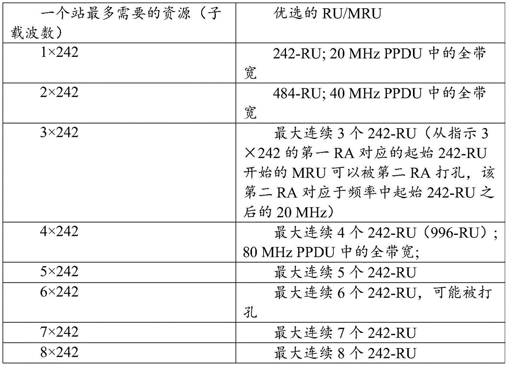
Table 1 below is an example of required resources (in particular less than 20MHz) and preferred RUs or MRUs based on the required resources.
TABLE 1

The new table of RU allocation subfields is based on one or more of the above-mentioned RU/MRUs, and may also take into account the number of MRUs, the location of each RU in the MRUs. The more flexible the MRU, the more indexes are needed. The preferred RU/MRU may be defined and limited to reduce the complexity of RU allocation subfields.
Table 2 below is another example of required resources (particularly greater than 20MHz, supporting 320MHz bandwidth) and preferred RUs or MRUs based on the required resources.
TABLE 2


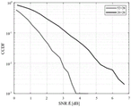
To reduce the complexity of the indication and to more efficiently meet the resource requirements, a preferred MRU is provided. Referring to fig. 13, simulation results show that combining the best 26-RU with RU >26 results in MRU with negligible SNR gain, where combining the best 26-RU with a given 26-RU results in >3dB SNR.
Thus, for the 20MHz band, in an example, a preferred MRU includes a combination of the middle 26-RU and its consecutive 52-RU/106-RU, or a combination of 2 26-RUs different from the 52-RU that has been defined. It may also be referred to as the aggregate middle 26-RU and its consecutive 52-RU or 106-RU, or the aggregate non-consecutive 26-RU.
But even with the above constraints, too many entries are needed to support other MRU combinations, so extending the RU allocation table may be impractical in some cases.
TABLE 3


Referring to table 3, too many entries are needed to support other MRU combinations, such as: 2 concurrent MRUs consisting of 2X 26-RU. Therefore, in alternative embodiment 3, instead of extending the RU allocation subfield to a large dimension, a new field for indicating the size and position of each RU aggregated in the MRU is included, which may be referred to as a common MRU. An example is shown in fig. 14.
The common MRU field exists only if there is any MRU in the PPDU (in any 20MHz channel). Thus, the common MRU field may be signaled in the U-SIG preceding the EHT-SIG or as an additional bit/field in the common field of the EHT-SIG.
For small MRUs:
the common MRU field is separately encoded.
The common MRU field includes 3 bitmap subfields, as follows:
MRU _1, which may be 9 bits, indicates which 26-RUs are included in the first MRU.
MRU _2, which may be 7 bits, indicates which 26-RUs are included in the second MRU.
MRU _3, which may be 5 bits, indicates which 26-RUs are included in the third MRU.
Therefore, an additional 21 bits (22 bits, including a signaling bit indicating whether an MRU is present or not) are needed to signal any combination of up to 3 MRUs per 20MHz band.
Since the number of user fields in the user specific field is reduced, additional bits will be saved later.
In this embodiment, although the common NRU field may seem more costly, we should remember that a larger amount of additional bits will be saved later due to the reduced number of user fields in the user-specific field.
For large MRUs:
for RU > -242 tones, a large MRU is identified by the corresponding RU allocation subfield.
In this case, the common MRU field (bitmap) indicates which other RUs (>242) correspond to the same MRU.
MRU _1 — may be 8 bits (omit bit 9): indicating which 242-RUs belong to the MRU
MRU _ 2-omission
MRU _ 3-omission
Similar to the case of small MRUs, the overhead of user-specific fields is also reduced. That is, for the indicated MRU, one or more user fields are included, and the ID of the station is not repeated in different user fields. The number, station, or user field indicated by the RU allocation field still functions when the station determines which RU/MRUs are allocated to the station.
User-specific fields are included in the EHT-SIG, with each RU/MRU indicated by the RU allocation subfield and/or the common MRU field mapped to one or more user fields, typically the user fields are mapped to MRU/RUs in turn. Since the location of the RUs in the MRU may be alternating, there should be some rules for mapping the MRU and the user field or fields assigned to the MRU. In an example, the location of the MRU is specified by the location of the first RU in the lowest frequency domain. Referring to fig. 17a, based on the frequency order of 26-RU1,26-RU 2, and 52-RU2, MRU1 is one MRU where 26-RU1 is the lowest RU, MRU2 is one MRU where 26-RU2 is the lowest RU, and MRU3 is one MRU where 52-RU2 is the lowest RU.
One or more user fields of the MRU/RU may be mapped to the MRU/RU in a similar manner as in 802.11 ax. The user field location of the MRU will coincide with the lowest frequency RU shown in the 2 examples in fig. 15 and 1010. In another understanding, each user field of the MRU points to the first RU of the MRU (the RU located at the lowest frequency).
For an MRU larger than 242-RU (or 106RU), MU-MIMO is supported and the number of user fields corresponding to the MRU is indicated. When the content is divided into CC1 and CC2, the number of user fields corresponding to MRUs in CC1 and CC2, respectively, is indicated.
In this solution, the STA can decode the user specific field in a similar manner as in 802.11 ax. When decoding user-specific fields, the STA uses RU/MRU allocation or structure (signaled in common fields) to obtain user fields on RU/MRU. The remaining RUs of the same MRU are skipped, if necessary.
For the example of FIG. 15, the MRUs 1 include 26-RU-1 and 26-RU 3, the sequence/order position of the MRU/RU is [ MRU1,26-RU 2,26-RU 4,26-RU 5,52-RU 3,52-RU 4], and the user fields are mapped to the MRU/RU in turn. For the example of FIG. 16, the MRU1 includes 52-RU2 and 26-RU 5, the sequence/order of the MRU/RU is positioned [26-RU1,26-RU 2, MRU1,52-RU 3,52-RU 4], and the user fields are mapped to the MRU/RU in turn.
FIG. 17a shows an example of an RU/MRU allocation comprising 3M-RUs in a 20MHz band. Referring to fig. 17b, the complete common field '10000111000001101001110011111' includes an MRU indication, an RU allocation subfield, a first MRU bitmap, a second MRU bitmap, and a third MRU bitmap. The details are as follows:
the MRU indication is 1 bit, indicating whether there are any MRUs in the allocation;
the RU allocation subfield may be 8, 9, or 10 bits indicating a sequence of RUs (size and position of each RU) corresponding to the 20MHz band. In this example, "00000111" indicates an allocation of [26,26,52, middle 26,52,52 ].
The first MRU bitmap is labeled MRU _1, indicating which 26-RUs are in the first MRU. In this example, 100000011 indicates that the first, eighth, and ninth 26-RUs are combined as the first MRU. The first MRU bitmap typically starts with a1 (MSB is 1), indicating that the MRU includes a 26-RU for the left edge.
The second MRU bitmap is labeled MRU _2, indicating which 26-RUs are in the second MRU. In this example, 0100011 indicates that the second, sixth, and seventh 26-RUs are combined into a second MRU. Only 6 bits are needed and thus the MSB is 0.
The third MRU bitmap is labeled MRU _3, indicating which 26-RUs are in the third MRU. In this example, 00111 denotes that the second, sixth, and seventh 26-RUs are combined into a second MRU. Only 3 bits are needed and thus the 2MSB is 0.
In FIG. 17c, based on the same example of RU/MRU allocation, the following alternative solutions are provided: RU allocation field in common field of EHT-SIG: the size and location of the RUs of the frequency band are indicated, and the common field of the EHT-SIG further includes one or more common MRU fields, each common MRU field indicating an RU among the MRUs indicated by the RU allocation field (i.e., an allocated RU). This differs from fig. 17b in that granularity is used for the indication of MRU. Preferably, the length of the common MRU field decreases in an order, the order of the common MRU field being based on the first RU in the MRU in the frequency domain.
For example, the RU allocation field is set to 00000111.
Common MRU field: using a bitmap corresponding to the actual number of RUs, each bit indicates whether there is an RU indicated by the RU allocation field in the MRU. The unused bit is set to "0".
The bits required in this solution may be much shorter than in fig. 17 b. Referring to fig. 17c, MRU _1 is 6 bits, MRU _2 is 4 bits, and MRU _3 is 2 bits.
RU allocation field: 00000111
The common MRU field 1(MRU _1) indicates which RU is in the first MRU. Such as 000100001. Only 6 bits 100001 are needed and therefore the 3MSB may be set to 0 or used for other functions, sometimes the first 3 bits may be omitted.
Common MRU field 2(MRU _ 2): 0001001. only 4 bits are needed and thus the 3MSB may be set to 0 or used for other functions or omitted.
Common MRU field 3(MRU _ 3): 00011. only 2 bits are needed and thus the 3MSB may be set to 0 or for other functions.
The order of the common MRU fields coincides with the order of the first RU in the MRU in the frequency domain. See fig. 17 a.
FIG. 18 provides a solution indicating RU/MRU allocation per 160MHz BW for a large MRU. In this example, there are 2 MRUs, one MRU including 242-RU 1, 242-RU 3, 242-RU 4, and 242-RU 7 (shown in gray). Another MRU includes 242-RU 5, 242-RU 6, and 242-RU 8.
The EHT-SIG includes CC1 and CC 2. Information of the EHT-SIG may be divided into CC1 and CC2 to reduce overhead and improve robustness of the information.
The common fields of CC1 include: for odd numbered 20MHz bins or 40MHz bins, information (fields) is allocated for RUs per 20MHz bin or per 40MHz bin. For example, in this example, the 20MHz band is 11100 xxx.
The common fields of CC2 include: for even numbered 20MHz band or 40MHz band, RU allocation information (field) per 20MHz band or per 40MHz band. For example, in this example, the 20MHz band is 11100 xx.
In alternative solutions, the above-described common fields may be omitted by other solutions or indicated in the manner described in other embodiments.
MRU _1 is valid, and is 8 bits long.
The MRU _1 field in CC1 also corresponds to the odd numbered 20MHz segment or 40MHz segment. In the example of fig. 18, the first four bits map to the 1 st, 3 rd, 5 th, and 7 th 20MHz segments, respectively, in the primary 160MHz or unique 160MHz BW. If BW is 320MHz, the following four bits are mapped to the 9 th, 11 th, 13 th, and 15 th 20MHz segments, respectively.
The MRU _1 field in CC2 also corresponds to an even numbered 20MHz segment or a 40MHz segment. In the example of fig. 18, the first four bits map to the 1 st, 3 rd, 5 th, and 7 th 20MHz segments in the primary 160MHz or unique 160MHz BW, respectively. If BW is 320MHz, the following four bits are mapped to the 9 th, 11 th, 13 th, and 15 th 20MHz segments, respectively.
Similarly, the MRU _2 field indicates an RU in MRU _2 by a similar method of the MRU _1 field.
In some solutions, MRU _2 and MRU _3 are omitted based on the MRU signal bit and the RA subfield in the common part.
Fig. 19 provides an example of a transmission including a mixed MRU (large MRU and small MRU). In this example, 242-RU 2 is allocated as a small MRU, e.g., of FIGS. 17a and 14b, and the other 242-RUs are allocated in a large MRU, e.g., of FIG. 18.
The RA field (RA 2 including 242-RU 2) is located in a common portion of the EHT-SIG in a similar manner to fig. 18.
A small MRU _1/2/3 field may be added in CC2 at the location of the MRU field corresponding to RA 2.
In this embodiment, by providing a common sub-field with the MRU bitmap, a number of technical advantages are obtained: any combination of MRUs may be defined and extended RU allocation subfields may be avoided, making the implementation more practical and also reducing the overall overhead in the EHT-SIG.
Example 4
In this embodiment, it is allowed to allocate MRU to one station, and preamble puncturing (preamble puncturing) is also considered. This embodiment is applicable in the case of allocation of large RUs (RU >484), such as 996-RU or 1992-RU (2 × 996-RU) or 3984-RU (2 × 996-RU), where some of the 20MHz portions comprised by these RUs are punctured. In this case, the information on channel puncturing that is already available is used to define a large punctured RU as a single RU, rather than several smaller RUs. This information may be available in a field preceding the EHT-SIG, which may be referred to as "U-SIG", and may be indicated by 2 or more than 2 bits. The common portion of the EHT-SIG does not include information regarding puncturing of the sub-channels (20 MHz).
It is assumed that puncturing occurs frequently (especially in dense networks). Referring to RU >484, puncturing information (possibly defined in U-SIG) is included in the SIG to define or indicate a non-continuous large RU (punctured RU), so the SIG may also include a single user-specific field (in EHT-SIG) in which one or more user fields are included to correspond to the non-continuous large RU. The one or more user fields each include information for different stations. Therefore, the stations are allocated to non-consecutive large RUs by MU-MIMO.
Fig. 20 shows an example of the above-described embodiment in a bandwidth of 160 MHz. In this example, a first 996-RU is allocated to STA1, with a second 242-RU punctured, equal to the first 242-RU and the second 484-RU allocated to STA 1. A second 996-RU is allocated to STA2, where the second 242-RU is punctured and the sixth 242-RU and the eighth 242-RU are allocated to STA 2. In this example, the frequency resources allocated to STA1 may be defined or considered as one punctured 996-RU (shown as primary 80 MHz). A single user-specific field (where different user fields have information of different stations) may be included in the EHT-SIG to correspond to the 996-RU being punctured, instead of the case of embodiment 1, i.e., two RUs require two user fields, where the first user field corresponds to the first 242-RU and the second user field corresponds to the second 484-RU, the first and second user fields including the same ID of the station. Similarly, the frequency resources allocated to STA2 may also be defined or considered as one punctured 996-RU (shown as 80MHz second). A single RU may be included in the EHT-SIG to correspond to the 996-RU that is punctured, instead of the case of embodiment 1, i.e., two RUs require two user fields, where the first user field corresponds to the sixth 242-RU and the second user field corresponds to the eighth 242-RU.
When the STA knows that it is assigned RU-996, the STA already knows that this RU is punctured.
Reducing overhead
Furthermore, any receiver (especially wyshi's device) that supports the proposed method described above can easily decode the signal defined by the same proposed method, thereby disclosing the use of the invention by a competitor's transmitter.
Example 5
As described in embodiment 3, a new table may be defined in which a newly defined MRU is also indicated by the index/bit sequence defined in the RU allocation subfield.
The RU allocation subfield (RA) may be 8 bits, 9 bits, 10 bits, or more bits corresponding to a 20MHz segment. The more bits in the RA, the more MRUs are supported, i.e., one or more of the MRUs listed above may be in an RU allocation and indicated by an index corresponding to the RU allocation. When more stations can be allocated to an RU or MRU, more bits are needed to indicate the number of stations. When the MRU in the RU allocation and the number of stations on the MRU are indicated, the mapping between RU/MRU and user field is indicated by the sequence of RU/MRU and the sequence of station/user field, i.e. one-to-one mapping in order.
As described above, RU allocation is decided by the AP according to various criteria. The resources required by the station in the transmission are taken into account when determining the preferred RU or MRU.
To reduce the complexity of the table, a preferred allocation or a restricted allocation of RUs or MRUs is defined in the table, not allowing for an inefficient RU/MRU allocation.
Table 4 below is an example of required resources (particularly less than 20MHz) and preferred RUs or MRUs based on the required resources.
TABLE 4

The new index table of RU allocation subfields may need to consider the above-mentioned preferred RU/MRU, and may also consider the number of MRUs, and the position of each RU in the MRU. The more flexible the MRU, the more indexes are needed.
Table 5 below is another example of required resources (particularly greater than 20MHz, supporting 320MHz bandwidth) and preferred RUs or MRUs based on required resources that require entries in the index table of RU allocation subfields.
TABLE 5

The maximum contiguous M242-RUs (large MRUs) above are defined and mapped to an index, the large MRUs starting from a starting 242-RU in the frequency domain, indicating that a starting RA of mx242 (indicating a first RA in the common part of the EHT-SIG of the mx242 MRU) corresponds to the starting 242-RU, which may be punctured in the frequency domain by a second RA corresponding to 20MHz after the starting 242-RU.
Table 6 below may further limit large MRUs that require entries in the index table of RU allocation subfields.
TABLE 6
The large MRU can be further reduced.
The entries required for each large MRU may be based on the number of stations that can be allocated on the large MRU. For example, when 16 stations of MU-MIMO are supported, the entries for each large MRU may be 16. The value of the index is not limited, and 2 bits, 3 bits, or 4 bits in the index are used to indicate the number of stations on a large MRU.
Based on the above solution, for the example in fig. 6, in 160MHz, the first, third, fourth, and fifth 242-RUs are allocated to STA 1; the sixth, eighth 242-RU is allocated to STA 2. RU allocations may be indicated by the following common portions of EHT-SIG:
the common portion of CC1 includes "RA-1, indicating a5 × 242MRU (n 1)); RA-3, indicating a5 × 242MRU (n 1); RA-5, indicating a5 × 242MRU (n 1); RA-7, indication 242(n4) ";
the common portion of CC2 includes "RA-2, indication 242(n 2); RA-4, indicating a5 × 242MRU (n 1); RA-6, indicating 3X 242MRU (n3), RA-8, indicating 3X 242MRU (n3) ".
n1, n2, n3, n4 are the number of stations on the large MRU in CC1 or CC 2.
In the above embodiments, only the common part of the EHT-SIG is discussed, the user specific fields may be similar to the 802.11ax solution. The sequence of user fields is located in the user-specific field of the corresponding EHT-SIG, mapped to the RU or MRU in the allocation indicated by the RA field.
In some special cases, other types of MRUs may be indicated by the user field in addition to the MRU indicated by the RA field.
Example 6
Embodiments may be combined in a manner in which they may work and modified in a manner that still works or works better, some examples of which follow. In embodiment 6a, a signaling method for a small RU is provided, in which an indication field in a common part of an EHT-SIG is composed of two fields (an existing RA field and additional signaling of MRU allocation).
This method allows any combination of small RUs to be defined as MRU while preserving the definition of the 802.11ax 20MHz allocation map (RU allocation subfield).
The indication includes an RA field and additional signaling indicating which RUs defined in the RA field are allocated as MRUs.
For example, if we want to assign the following mapping
{26,26+52, intermediate 26,26,26,52 };
where the second 26-RU and the second 52-RU comprise MRUs, we first indicate an 8-bit RA field '00000101' that defines an allocation map of {26,26,52, middle 26,26,26,52 };
then, the MRU consisting of the second 26-RU and the second 52-RU is specifically indicated.
In this approach, a single user-specific field will be indicated in the EHT-SIG for each MRU, see the single user-specific fields specified in the above embodiments.
Example 6a
In this embodiment, a method of indicating MRU allocation using a bitmap is provided, where each bit corresponds to a particular RU defined in the RA field.
Up to 4 MRUs may be included per 20MHz, so the MRU allocation field will include 4 parts. In alternative solutions, it may be permissible to include 1,2, or 3 MRUs.
First part-the first MRU may be any combination of RUs defined in the RA field.
The maximum number of RUs in 20MHz is 9, so to cover all possible allocations we use 9 bits. The actual number of bits used for MRU allocation will be equal to the number of RUs defined in the RA field of 9 bits starting from the LSB or MSB. If the number of RUs defined in the RA field is less than 9, the redundant bit is an don't-care bit.
For example, the RA field '00000101' defines RU allocation of [26,26,52, middle 26,26,26,52 ];
bitmap 0011000 means that the second 52-RU and the middle 26-RU are allocated as MRUs, and two independent bits will be added to the bitmap.
Second part-the second MRU may be any combination of those RUs defined in the RA field and not included in the first MRU.
The maximum number of RUs not included in the first MRU is 7, so we use a 7-bit bitmap. The actual number of bits for the second MRU will be equal to the number of RUs defined in the RA field of 7 bits starting from the LSB or MSB minus the number of RUs included in the first MRU, the redundant bits being extraneous bits.
For example, the bitmap 11000 means that the first 26-RU and the second 26-RU are allocated as MRUs, and two extraneous bits will be added to the bitmap, according to the allocation defined in the previous section.
Third part-the third MRU may be any combination of those RUs defined in the RA field and not included in the first and second MRUs.
The maximum number of RUs not included in the first MRU and the second MRU is 5, so we use a bitmap of 5 bits. The actual number of bits for the second MRU will be equal to the number of RUs defined in the RA field of 5 bits starting from the LSB or MSB minus the number of RUs included in the first MRU and the second MRU, the redundant bits being extraneous bits.
For example, the bitmap 011 means that the seventh 26-RU and the fourth 52-RU are allocated as MRUs according to the allocations defined in the first two sections.
Fourth section — the fourth MRU may be any combination of those RUs defined in the RA field and not included in the first, second, and third MRUs.
The maximum number of RUs not included in the first, second, and third MRUs is 3, so we use a 3-bit bitmap.
In this example, the common fields of the EHT-SIG include: one or more RA fields (8 bits each) and one or more MRU allocation fields (9 bits, 7 bits, 5 bits, 3 bits, respectively).
In some alternative solutions, if a restricted mode of the MRU is defined, the embodiment may also be modified accordingly, e.g. only including bits that are allowed to be aggregated to the RU of the MRU. For example, when only 26RU-3, 26RU-4, 26RU-5, 26RU-6, 26RU-7 are allowed to be aggregated to the MRU, the first MRU allocation field and the second MRU allocation field may occupy 5 bits, 3 bits, respectively.
Example 6b
In this embodiment, a method similar to embodiment 6a is provided, and all bits using the bitmap of each part defined in embodiment 6a are used to indicate the allocated MRU, with no extraneous bits. Each bit in the bitmap corresponds to a particular 26-RU, while RUs greater than 26 will be indicated by consecutive bits in the bitmap. For example, to assign the first 52-RU and the last 52-RU as the first MRU, we will define a bitmap '110000011', where the first two "1's correspond to the first 52-RU and the last two" 1's correspond to the last 52-RU.
In the method, the common field of the EHT-SIG is composed of an RA field of 8 bits and an MRU allocation field of 9+7+5+3 bits.
Example 6c
In this embodiment, a method similar to that of embodiments 6a and 6b is provided, and the number of MRUs is indicated by the N _ MRU field in the EHT-SIG. If the N _ MRU field is set to zero, this means that no MRU is allocated and the common field of the EHT-SIG will not include a bitmap. If the N _ MRU field is set to a number between 1/2/3/4, then 1/2/3/4 MRUs are allocated as defined in embodiments 6a and 6b, and a corresponding number of bitmaps will be included.
In the method, the common fields of the EHT-SIG include: one or more RA fields (8 bits) and an MRU allocation field of zero bits or 9+7+5+3 bits according to the number of MRUs indicated by the N _ MRU bit.
Example 6d
In this embodiment, an additional resource allocation table is defined, which includes all the defined MRU combinations. It may be an MRA field-a multi-resource allocation field. Each entry definition of the MRA may include a mapping of a single MRU or a combination of MRUs. This mapping only defines MRU, while the full allocation mapping for 20MHz is defined by the RA field.
For example, if the following 20MHz mapping is to be allocated:
[26,26,52+ intermediate 26,26,26,52 ];
then the RA field '00000101' would indicate a mapping of [26,26,52, intermediate 26,26,26,52 ];
and a new MRA entry may be defined in which the second 52-RU and the middle 26-RU are allocated as a single MRU.
The new MRA field will not indicate any single RU, only the MRU, so any RA field entries that allocate the second 52-RU and the middle 26-RU may be combined with the MRA field that allocates those RUs as MRUs.
In the method, the common portion of the EHT-SIG includes one or more RA fields (each of 8 bits) and an additional N-bit MRA field.
The number of N bits defines the size of the MRA table with the 2^ N bit option of the MRU mapping.
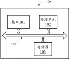
Fig. 21 is a block diagram of an access point according to another embodiment of the present invention. The access point of fig. 21 comprises an interface 101, a processing unit 102, and a memory 103. Processing unit 102 controls the operation of access point 100. Memory 103 may include both read-only memory and random access memory, and provides instructions and data to processing unit 102. A portion of the memory 103 may also include non-volatile random access memory (NVRAM). All components of access point 100 are coupled together using a bus system 109, and bus system 109 includes a power bus, a control bus, and a status signal bus in addition to a data bus. However, for clarity of illustration, in FIG. 21, the various buses are labeled as bus system 109.
The methods for transmitting the various frames disclosed in the above embodiments of the present invention may be applied to the processing unit 102 or implemented by the processing unit 102. In implementation, each step of the above method may be performed by instructions in the form of hardware, integrated logic circuits, or software in the processing unit 102. The processing unit 102 may be a general purpose processor, a digital signal processor, an application specific integrated circuit, a field programmable gate array or another programmable logic device, discrete gate or transistor logic, or discrete hardware components, and may implement or perform the various methods, steps, and logic blocks disclosed in embodiments of the present invention. A general purpose processor may be a microprocessor, any conventional processor, or the like. The steps of a method disclosed with reference to embodiments of the invention may be performed directly by a hardware processor or may be performed using a combination of hardware and software modules in a processor. The software modules may reside in a storage medium well known in the art such as random access memory, flash memory, read only memory, programmable read only memory, electrically erasable programmable memory, or registers. The storage medium is located in the memory 103. The processing unit 102 reads the information in the memory 103 and performs the steps of the above method with reference to the hardware of the processing unit 102.
Fig. 22 is a block diagram of a station according to another embodiment of the present invention. The station comprises an interface 111, a processing unit 112, and a memory 113. The processing unit 112 controls the operation of the station 110. Memory 113 may include both read-only memory and random access memory and provides instructions and data to processing unit 112. A portion of the memory 113 may also include non-volatile random access memory (NVRAM). All components of station 110 are coupled together using a bus system 119, and bus system 119 includes, in addition to a data bus, a power bus, a control bus, and a status signal bus. However, for clarity of illustration, in FIG. 22, the various buses are labeled as the bus system 119.
The methods for transmitting the various frames described above disclosed in the above embodiments of the present invention may be applied to the processing unit 112, or implemented by the processing unit 112. In implementation, each step of the above method may be performed by instructions in the form of hardware, integrated logic circuits, or software in the processing unit 112. The processing unit 112 may be a general purpose processor, a digital signal processor, an application specific integrated circuit, a field programmable gate array or another programmable logic device, discrete gate or transistor logic, or discrete hardware components, and may implement or perform the various methods, steps, and logic blocks disclosed in embodiments of the present invention. A general purpose processor may be a microprocessor, any conventional processor, or the like. The steps of a method disclosed with reference to embodiments of the invention may be performed directly by a hardware processor or may be performed using a combination of hardware and software modules in a processor. The software modules may reside in a storage medium well known in the art such as random access memory, flash memory, read only memory, programmable read only memory, electrically erasable programmable memory, or registers. The storage medium is located in the memory 113. The processing unit 112 reads the information in the memory 113 and performs the steps of the above method with reference to the hardware of the processing unit 112.
Specifically, the memory 113 stores reception information that enables the processing unit 112 to execute the method described in the above-described embodiments.
The specific embodiments set forth above in connection with the attached drawings describe examples and are not intended to represent the only examples that may be implemented or are within the scope of the claims. The terms "example" and "exemplary" when used in this specification mean "serving as an example, instance, or illustration," and not "preferred" or "superior to other examples. The detailed description includes specific details for the purpose of providing an understanding of the described technology. However, the techniques may be practiced without these specific details. In some instances, well-known structures and devices are shown in block diagram form in order to avoid obscuring the concepts of the described examples.
Information and signals may be represented using any of a variety of different technologies and techniques. For example, data, instructions, commands, information, signals, bits, symbols, and chips that may be referenced throughout the above description may be represented by voltages, currents, electromagnetic waves, magnetic fields or particles, optical fields or particles, or any combination thereof.
The various illustrative blocks and components described in connection with the present disclosure may be implemented or performed with a general purpose processor, a Digital Signal Processor (DSP), an ASIC, FPGA, or other programmable logic device, discrete gate or transistor logic, discrete hardware components, or any combination thereof designed to perform the functions described herein. A general-purpose processor may be a microprocessor, but in the alternative, the processor may be any conventional processor, controller, microcontroller, or state machine. A processor may also be implemented as a combination of computing devices, e.g., a combination of a DSP and a microprocessor, a plurality of microprocessors, one or more microprocessors in conjunction with a DSP core, or any other such configuration.
The functions described herein may be implemented in hardware, software executed by a processor, firmware, or any combination thereof. If implemented in software executed by a processor, the functions described above may be stored on or transmitted over as one or more instructions or code on a computer-readable medium. Other examples and embodiments are within the scope and spirit of the disclosure and appended claims. For example, due to the nature of software, the functions described above may be implemented using software executed by a processor, hardware, firmware, hardwire, or any combination thereof. Features that perform a function may also be physically located at various locations, including being distributed such that portions of the function are performed at different physical locations. As used herein, including in the claims, the term "and/or," when used in a list of two or more items, means that any one of the listed items can be used alone, or any combination of two or more of the listed items can be used. For example, if a composition is described as comprising component A, B, and/or C, the composition may comprise a only; only B is contained; only C is contained; comprises A and B; comprises A and C; comprises B and C; or contain A, B, C. Further, as used herein, including in the claims, "or" as used in a list of items (e.g., a list of items beginning with the phrase "at least one" or "one or more") means a disjunctive list, thus, for example, a list of "A, B, or at least one of C" means a or B or C or AB or AC or BC or ABC (i.e., a and B and C).
Computer-readable media includes both computer storage media and communication media including any medium that can be used to transfer a computer program from one place to another. A storage media may be any available media that can be accessed by a general purpose or special purpose computer. By way of example, and not limitation, computer-readable media can comprise RAM, ROM, EEPROM, flash memory, CD-ROM or other optical disk storage, magnetic disk storage or other magnetic storage devices, or any other medium which can be used to carry or store desired program code means in the form of instructions or data structures and which can be accessed by a general-purpose or special-purpose computer, or a general-purpose or special-purpose processor. Also, any connection is properly termed a computer-readable medium. For example, if the software is transmitted from a website, server, or other remote source using a coaxial cable, fiber optic cable, twisted pair, Digital Subscriber Line (DSL), or wireless technologies such as infrared, radio, and microwave, etc., then the coaxial cable, fiber optic cable, twisted pair, DSL, or wireless technologies such as infrared, radio, and microwave, etc. are included in the definition of medium. As used herein, disk and disc (disc) includes Compact Disc (CD), laser disc, optical disc, Digital Versatile Disc (DVD), floppy disk, and blu-ray disc where disks usually reproduce data magnetically, while discs reproduce data optically with lasers. Combinations of the above are also included within the scope of computer-readable media.
The previous description of the disclosure is provided to enable any person skilled in the art to make or use the disclosure. Various modifications to the disclosure will be readily apparent to those skilled in the art, and the generic principles defined herein may be applied to other variations without departing from the scope of the disclosure. Thus, the disclosure should not be limited to the examples and designs described herein, but should be accorded the widest scope consistent with the principles and novel features disclosed herein.
It should be appreciated that reference throughout this specification to "an embodiment" or "one embodiment" does not imply that a particular feature, structure, or characteristic described in connection with the embodiment is included in at least one embodiment of the present invention. Thus, appearances of the phrases "in an embodiment" or "in one embodiment" in various places throughout this specification are not necessarily all referring to the same embodiment. Furthermore, the particular features, structures, or characteristics may be combined in any suitable manner in one or more embodiments. In various embodiments of the present invention, the sequence numbers of the above-described processes do not imply an order of execution. The execution order of the above-described processes should be determined according to the functions and internal logic of the above-described processes, and should not be construed as any limitation to the implementation process of the embodiments of the present invention.
Those of ordinary skill in the art will appreciate that the elements and algorithm steps described in connection with the embodiments disclosed herein may be implemented as electronic hardware, computer software, or combinations of both. To clearly illustrate this interchangeability of hardware and software, various illustrative components and steps have been described above generally in terms of their functionality. Whether such functionality is implemented as hardware or software depends upon the particular application and design constraints imposed on the technical solution. Skilled artisans may implement the described functionality in varying ways for each particular application, but such implementation decisions should not be interpreted as causing a departure from the scope of the present invention.
It will be clearly understood by those skilled in the art that for convenience and brevity of the description, reference may be made to corresponding processes in the above-described method embodiments for detailed operation of the above-described systems, apparatuses, and units, which will not be described in detail herein.
In the several embodiments provided in this application, it should be understood that the disclosed systems, apparatuses, and methods may be implemented in other ways. For example, the described apparatus embodiments are only examples. For example, the cell division is only a logical functional division, and other divisions are possible in actual implementation. For example, various elements or components may be combined or integrated in another system or some features may be omitted, or not implemented. Further, the shown or discussed mutual coupling or direct coupling or communicative connection may be realized by some interfaces. An indirect coupling or communicative connection between devices or units may be achieved in an electronic, mechanical, or other form.
Elements described as separate parts may or may not be physically separate, and parts shown as elements may or may not be physical elements, may be located in one position, or may be distributed over a plurality of network elements. Some or all of the units may be selected according to actual needs to achieve the objectives of the solution of the embodiments of the present invention.
In addition, the functional units in the embodiments of the present invention may be integrated into one processing unit, or each unit may exist alone physically, or two or more units are integrated into one unit. The integrated unit may be implemented in the form of hardware or may be implemented in the form of a software functional unit.
Claims (20)
1. An apparatus for wireless communication, comprising:
a memory storing instructions; and
a processor coupled with the memory, wherein the processor and the memory are configured to:
generating a signaling field (SIG) in a Wireless Local Area Network (WLAN), the SIG including a Resource Unit (RU) allocation field indicating a size and a position of each RU in a frequency resource, the SIG further including one or more user fields, each user field including information of a scheduling Station (STA); wherein the MRU including the plurality of RUs is allowed to be allocated to the same STA or STAs;
transmitting the SIG.
2. An apparatus for wireless communication, comprising:
a memory storing instructions; and
a processor coupled with the memory, wherein the processor and the memory are to:
receiving a signaling field (SIG) in a Wireless Local Area Network (WLAN), the SIG including a Resource Unit (RU) allocation field indicating a size and a position of each RU in a frequency resource, the SIG further including one or more user fields, each user field including information of a scheduling Station (STA); wherein the MRU including the plurality of RUs is allowed to be allocated to the same STA or a plurality of STAs;
processing the SIG.
3. The apparatus of claim 1 or 2, wherein the MRU is a small MRU comprising a combination of 26-RU, 52-RU, or 106-RU in a 20MHz band; alternatively, the MRU is a large MRU comprising a combination of 242-RU, 484-RU, or 996-RU in the transmission bandwidth.
4. The apparatus of claim 1 or 2, wherein the MRU comprises a first RU and a second RU, the SIG comprises a first user field corresponding to the first RU and a second user field corresponding to the second RU; the first user field and the second user field both include a same ID of the STA.
5. The apparatus of claim 4, the second user field further comprising one or any combination of:
a number of RUs allocated to the STA; or alternatively
A size and a position of each RU in the MRU allocated to the STA.
6. The apparatus of claim 1 or 2, wherein the common field of the SIG includes information of a small MRU allocated in a corresponding 20MHz band; and/or information of the number of large MRUs allocated in the transmission bandwidth.
7. The apparatus of claim 1 or 2, the SIG comprising a single RU user field and an MRU user field; the single RU user field corresponds to an RU that is not an MRU; the MRU user field corresponds to an MRU, the MRU user field including at least: a STA _ ID and an RU bitmap indicating a size and position of each RU included in the MRU.
8. The apparatus of claim 1 or 2, wherein the SIG includes a common MRU field indicating which 26-RUs are included in MRUs in a corresponding 20MHz band; and/or indicating which 242-RUs to include in the MRUs in the transmission bandwidth.
9. The apparatus of claim 1 or 2, wherein the SIG includes one or more common MRU fields, each common MRU field indicating which actually allocated RUs in the MRUs.
10. The apparatus of claim 1 or 2, wherein the SIG comprises puncturing information indicating a non-continuous large RU and one or more user fields corresponding to the non-continuous large RU, each of the one or more user fields comprising information of a different station.
11. A method for wireless communication, comprising:
generating a signaling field (SIG) in a Wireless Local Area Network (WLAN), the SIG including a Resource Unit (RU) allocation field indicating a size and a location of each RU in frequency resources, the SIG further including one or more user fields, each user field including information of a scheduling Station (STA); wherein the MRU including the plurality of RUs is allowed to be allocated to the same STA or a plurality of STAs;
transmitting the SIG.
12. A method for wireless communication, comprising:
receiving a signaling field (SIG) in a Wireless Local Area Network (WLAN), the SIG including a Resource Unit (RU) allocation field indicating a size and a location of each RU in frequency resources, the SIG further including one or more user fields, each user field including information of a scheduling Station (STA); wherein the MRU including the plurality of RUs is allowed to be allocated to the same STA or a plurality of STAs;
processing the SIG.
13. The method of claim 11 or 12, wherein the MRU is a small MRU comprising a combination of 26-RU, 52-RU, or 106-RU in a 20MHz band; alternatively, the MRU is a large MRU comprising a combination of 242-RU, 484-RU, or 996-RU in the transmission bandwidth.
14. The method of claim 11 or 12, wherein the MRU comprises a first RU and a second RU, the EHT-SIG comprising a first user field corresponding to the first RU and a second user field corresponding to the second RU; the first user field and the second user field both include the same ID of the STA.
15. The method of claim 12, the second user field further comprising one or any combination of:
a number of RUs allocated to the STA; or alternatively
A size and a position of each RU in the MRU allocated to the STA.
16. The method of claim 11 or 12, the common field of the SIG comprising information of a small MRU allocated in a corresponding 20MHz band; and/or information of the number of large MRUs allocated in the transmission bandwidth.
17. The method of claim 11 or 12, the SIG comprising a single RU user field and an MRU user field; the single RU user field corresponds to an RU that is not an MRU; the MRU user field corresponds to an MRU, the MRU user field including at least: a STA _ ID and an RU bitmap indicating a size and position of each RU included in the MRU.
18. The method of claim 11 or 12, the SIG comprising a common MRU field indicating which 26-RUs are included in MRUs in a corresponding 20MHz band; and/or indicating which 242-RUs are included in MRUs in the transmission bandwidth.
19. The method of claim 11 or 12, the SIG comprising one or more common MRU fields, each common MRU field indicating which actually allocated RUs in the MRU.
20. The method of claim 11 or 12, the SIG comprising puncturing information indicating a non-consecutive large RU and one or more user fields corresponding to the non-consecutive large RU, each of the one or more user fields comprising information of a different station.
Priority Applications (1)
| Application Number | Priority Date | Filing Date | Title |
|---|---|---|---|
| CN202311101914.2A CN117220845A (en) | 2020-01-10 | 2020-01-10 | Resource allocation signaling in wireless LAN preamble |
Applications Claiming Priority (1)
| Application Number | Priority Date | Filing Date | Title |
|---|---|---|---|
| PCT/EP2020/050607 WO2021139900A1 (en) | 2020-01-10 | 2020-01-10 | Resource allocation signalng in awreless local areanetwork preamble |
Related Child Applications (1)
| Application Number | Title | Priority Date | Filing Date |
|---|---|---|---|
| CN202311101914.2A Division CN117220845A (en) | 2020-01-10 | 2020-01-10 | Resource allocation signaling in wireless LAN preamble |
Publications (1)
| Publication Number | Publication Date |
|---|---|
| CN114930962A true CN114930962A (en) | 2022-08-19 |
Family
ID=69174458
Family Applications (2)
| Application Number | Title | Priority Date | Filing Date |
|---|---|---|---|
| CN202311101914.2A Pending CN117220845A (en) | 2020-01-10 | 2020-01-10 | Resource allocation signaling in wireless LAN preamble |
| CN202080092353.2A Pending CN114930962A (en) | 2020-01-10 | 2020-01-10 | Resource allocation signaling in wireless local area network preamble |
Family Applications Before (1)
| Application Number | Title | Priority Date | Filing Date |
|---|---|---|---|
| CN202311101914.2A Pending CN117220845A (en) | 2020-01-10 | 2020-01-10 | Resource allocation signaling in wireless LAN preamble |
Country Status (10)
| Country | Link |
|---|---|
| US (2) | US12341721B2 (en) |
| EP (1) | EP4079072A1 (en) |
| JP (3) | JP7447280B2 (en) |
| KR (1) | KR20220124254A (en) |
| CN (2) | CN117220845A (en) |
| AU (1) | AU2020420882B2 (en) |
| BR (1) | BR112022013693A2 (en) |
| CA (1) | CA3164330A1 (en) |
| MX (1) | MX2022008607A (en) |
| WO (1) | WO2021139900A1 (en) |
Families Citing this family (10)
| Publication number | Priority date | Publication date | Assignee | Title |
|---|---|---|---|---|
| US12284631B2 (en) * | 2019-12-05 | 2025-04-22 | Lg Electronics Inc. | Technique for allocating resource unit in wireless communication system |
| MX2022008607A (en) | 2020-01-10 | 2022-10-20 | Huawei Tech Co Ltd | RESOURCE ALLOCATION SIGNALING IN WIRELESS LOCAL AREA NETWORK PREAMBLE. |
| WO2021167436A1 (en) * | 2020-02-20 | 2021-08-26 | 주식회사 윌러스표준기술연구소 | Method for transmitting and receiving data in wireless communication system, and wireless communication terminal |
| US12438681B2 (en) * | 2020-03-03 | 2025-10-07 | Mediatek Singapore Pte. Ltd. | Enhanced resource unit allocation subfield design for extreme high-throughput systems |
| WO2021206272A1 (en) * | 2020-04-09 | 2021-10-14 | 엘지전자 주식회사 | Tdma transmission in multi-ap environment |
| EP3910863B1 (en) * | 2020-04-23 | 2025-09-10 | Samsung Electronics Co., Ltd. | Communication based on a multi-resource unit in wireless local area network system |
| KR20230043135A (en) * | 2020-09-03 | 2023-03-30 | 엘지전자 주식회사 | Method and apparatus for allocating resources by limiting RU and MRU for STA operating only in 20MHZ in WLAN system |
| JP2025511198A (en) * | 2022-04-01 | 2025-04-15 | エルジー エレクトロニクス インコーポレイティド | Method and device for allocating resource units in a wireless LAN system |
| WO2024186118A1 (en) * | 2023-03-09 | 2024-09-12 | 엘지전자 주식회사 | Method and device for ppdu transmission/reception in wireless lan system |
| US20250203683A1 (en) * | 2023-12-15 | 2025-06-19 | Fortinet, Inc. | Management of multicast traffic using multi-link operation (mlo) in wi-fi 7 |
Citations (4)
| Publication number | Priority date | Publication date | Assignee | Title |
|---|---|---|---|---|
| US20170064718A1 (en) * | 2015-08-25 | 2017-03-02 | Qualcomm Incorporated | Resource allocation signaling in a wireless local area network preamble |
| CN108432173A (en) * | 2015-12-21 | 2018-08-21 | 高通股份有限公司 | Leading design aspect for efficient WLAN |
| US20190281640A1 (en) * | 2016-09-09 | 2019-09-12 | Nec Corporation | Wireless lan system, wireless lan base station, wireless lan terminal, and communication method |
| US20190380117A1 (en) * | 2018-06-11 | 2019-12-12 | Qualcomm Incorporated | Wireless communication with per-station punctured transmissions |
Family Cites Families (11)
| Publication number | Priority date | Publication date | Assignee | Title |
|---|---|---|---|---|
| US10582025B2 (en) * | 2015-05-05 | 2020-03-03 | Samsung Electronics Co., Ltd. | Efficient signaling and addressing in wireless local area network systems |
| WO2017027479A1 (en) * | 2015-08-07 | 2017-02-16 | Newracom, Inc. | Control information for multi-user transmissions in wlan systems |
| US11044056B2 (en) * | 2018-02-01 | 2021-06-22 | Mediatek Singapore Pte. Ltd. | Enhanced resource unit allocation schemes for OFDMA transmission in WLAN |
| US11539482B2 (en) * | 2018-05-04 | 2022-12-27 | Intel Corporation | Enhanced resource allocation for wireless communications |
| JP2019202783A (en) | 2018-05-21 | 2019-11-28 | 京セラドキュメントソリューションズ株式会社 | Shock absorber |
| US11395185B2 (en) * | 2019-06-06 | 2022-07-19 | Intel Corporation | Extreme high throughput signaling structure |
| WO2021075932A1 (en) * | 2019-10-17 | 2021-04-22 | 엘지전자 주식회사 | Signaling for multiple ru allocation |
| SG10201910444QA (en) * | 2019-11-07 | 2021-06-29 | Panasonic Ip Corp America | Communication apparatus and communication method for control signaling |
| JP7527772B2 (en) * | 2019-11-07 | 2024-08-05 | キヤノン株式会社 | COMMUNICATION DEVICE, CONTROL METHOD, AND PROGRAM |
| US12219590B2 (en) * | 2019-11-27 | 2025-02-04 | Qualcomm Incorporated | Parser and interleaving parameter design for resource unit aggregation |
| MX2022008607A (en) | 2020-01-10 | 2022-10-20 | Huawei Tech Co Ltd | RESOURCE ALLOCATION SIGNALING IN WIRELESS LOCAL AREA NETWORK PREAMBLE. |
-
2020
- 2020-01-10 MX MX2022008607A patent/MX2022008607A/en unknown
- 2020-01-10 AU AU2020420882A patent/AU2020420882B2/en active Active
- 2020-01-10 CA CA3164330A patent/CA3164330A1/en active Pending
- 2020-01-10 WO PCT/EP2020/050607 patent/WO2021139900A1/en not_active Ceased
- 2020-01-10 KR KR1020227027693A patent/KR20220124254A/en active Pending
- 2020-01-10 JP JP2022542308A patent/JP7447280B2/en active Active
- 2020-01-10 EP EP20700980.4A patent/EP4079072A1/en active Pending
- 2020-01-10 CN CN202311101914.2A patent/CN117220845A/en active Pending
- 2020-01-10 CN CN202080092353.2A patent/CN114930962A/en active Pending
- 2020-01-10 BR BR112022013693A patent/BR112022013693A2/en unknown
-
2022
- 2022-07-08 US US17/860,735 patent/US12341721B2/en active Active
-
2024
- 2024-02-28 JP JP2024028313A patent/JP7743556B2/en active Active
-
2025
- 2025-05-19 US US19/211,617 patent/US20250279867A1/en active Pending
- 2025-09-09 JP JP2025148960A patent/JP2026000975A/en active Pending
Patent Citations (4)
| Publication number | Priority date | Publication date | Assignee | Title |
|---|---|---|---|---|
| US20170064718A1 (en) * | 2015-08-25 | 2017-03-02 | Qualcomm Incorporated | Resource allocation signaling in a wireless local area network preamble |
| CN108432173A (en) * | 2015-12-21 | 2018-08-21 | 高通股份有限公司 | Leading design aspect for efficient WLAN |
| US20190281640A1 (en) * | 2016-09-09 | 2019-09-12 | Nec Corporation | Wireless lan system, wireless lan base station, wireless lan terminal, and communication method |
| US20190380117A1 (en) * | 2018-06-11 | 2019-12-12 | Qualcomm Incorporated | Wireless communication with per-station punctured transmissions |
Also Published As
| Publication number | Publication date |
|---|---|
| JP7743556B2 (en) | 2025-09-24 |
| JP2026000975A (en) | 2026-01-06 |
| JP2024073477A (en) | 2024-05-29 |
| AU2020420882A1 (en) | 2022-08-11 |
| US20250279867A1 (en) | 2025-09-04 |
| MX2022008607A (en) | 2022-10-20 |
| KR20220124254A (en) | 2022-09-13 |
| CA3164330A1 (en) | 2021-07-15 |
| BR112022013693A2 (en) | 2022-09-06 |
| CN117220845A (en) | 2023-12-12 |
| JP2023510337A (en) | 2023-03-13 |
| US20220345276A1 (en) | 2022-10-27 |
| EP4079072A1 (en) | 2022-10-26 |
| WO2021139900A1 (en) | 2021-07-15 |
| US12341721B2 (en) | 2025-06-24 |
| AU2024201605A1 (en) | 2024-03-28 |
| AU2020420882B2 (en) | 2024-03-28 |
| JP7447280B2 (en) | 2024-03-11 |
Similar Documents
| Publication | Publication Date | Title |
|---|---|---|
| JP7743556B2 (en) | Resource allocation signaling in wireless local area network preambles | |
| CN116388943B (en) | Resource unit indication method, device and storage medium | |
| US10231225B2 (en) | Preamble design aspects for high efficiency wireless local area networks | |
| US20170064718A1 (en) | Resource allocation signaling in a wireless local area network preamble | |
| JP6426842B2 (en) | Method and apparatus for allocating resource units based on container in wireless LAN | |
| EP3910864B1 (en) | Apparatus and method of communication based on extended bandwidth and multi-resource unit in wireless local area network system | |
| AU2021206097B2 (en) | Information indication method and communications apparatus | |
| CN113890704B (en) | Apparatus and method for communication based on multiple resource units in a wireless local area network system | |
| KR20210141314A (en) | Apparatus and method for communication based on extended bandwidth and multi-resource unit in wireless local area network system | |
| CN118741700A (en) | Device and method for multi-resource unit based communication in wireless local area network system |
Legal Events
| Date | Code | Title | Description |
|---|---|---|---|
| PB01 | Publication | ||
| PB01 | Publication | ||
| SE01 | Entry into force of request for substantive examination | ||
| SE01 | Entry into force of request for substantive examination |