Disclosure of Invention
The application provides a photovoltaic system and a power supply current control method thereof, which can ensure reasonable distribution of loads among power supply units and have strong applicability.
In a first aspect, the present application provides a photovoltaic system, which includes a DC bus, at least two power supply units connected in parallel to the DC bus, and a DC/AC converter connected to the at least two power supply units through the DC bus, wherein each of the at least two power supply units includes a DC/DC converter, and an input terminal of the DC/DC converter is connected to a DC power supply. When the DC/AC converter is in a power limiting working mode, the DC/AC converter acquires current output state parameters of the DC/DC converter in each power supply unit, determines reference output current values of the DC/DC converter in each power supply unit according to the current output state parameters of the DC/DC converter in each power supply unit, and adjusts the current output power of the DC/DC converter in each power supply unit according to the reference output current values of the DC/DC converter in each power supply unit.
In the embodiment of the application, the DC/AC converter can adjust the current output power of each DC/DC converter according to the current actual power supply capability of the DC/DC converter in each power supply unit connected in parallel to the DC bus, so as to ensure the output power balance among each DC/DC converter, and the applicability is strong.
With reference to the first aspect, in a first possible implementation, before the DC/AC converter is in the power-limited operation mode, the DC/AC converter determines that the current output power of the photovoltaic system is greater than a system output power threshold.
With reference to the first aspect, in a second possible implementation manner, the current output state parameter of the DC/DC converter in each power supply unit includes the current output power and the current output capability of the DC/DC converter in each power supply unit. The DC/AC converter adjusts the current output power of the DC/DC converter in each power supply unit according to the current output power and the current output capability of the DC/DC converter in each power supply unit so as to prevent one DC/DC converter or part of the DC/DC converters in the photovoltaic system from working in an extreme working state.
In the embodiment of the application, the DC/AC converters can adjust the current output power of each DC/DC converter according to the current actual output capability of each DC/DC converter connected in parallel to the DC bus, and ensure the output power balance among each DC/DC converter, thereby preventing one or part of the DC/DC converters in each DC/DC converter from operating with the output power exceeding the current maximum output power of the DC/DC converter, and having strong applicability.
With reference to the first aspect, in a third possible implementation manner, the current output state parameter of the DC/DC converter in each power supply unit includes a current maximum output power of the DC/DC converter in each power supply unit. The DC/AC converter determines a current maximum output power ratio of the current maximum output power of the DC/DC converter in each power supply unit among the sums of the current maximum output powers of the DC/DC converters in at least two power supply units based on the current maximum output power of the DC/DC converter in each power supply unit, and determines a reference output current value of the DC/DC converter in each power supply unit based on the current maximum output power ratio.
In the embodiment of the present application, in a case where the current output state parameter of each DC/DC converter includes the current maximum output power of each DC/DC converter, the reference output current value of each DC/DC converter may be determined according to the current maximum output power of each DC/DC converter.
With reference to the first aspect, in a fourth possible implementation manner, the current output state parameter of the DC/DC converter in each power supply unit further includes a current device operating condition parameter of the DC/DC converter in each power supply unit; the DC/AC converter determines the current corrected output power of the DC/DC converter in each power supply unit based on the current equipment working condition parameters and the current maximum output power of the DC/DC converter in each power supply unit, determines the current corrected output power ratio of the current corrected output power of the DC/DC converter in each power supply unit in the sum of the current corrected output powers of the DC/DC converter in at least two power supply units based on the current corrected output power of the DC/DC converter in each power supply unit, and determines the current corrected output power ratio as the current maximum output power ratio.
In the embodiment of the application, the DC/AC converter can determine the reference output current value of each DC/DC converter according to the current maximum output power of each DC/DC converter and the current equipment working condition parameter.
With reference to the first aspect, in a fifth possible implementation manner, the DC/AC converter obtains power attenuation coefficients corresponding to respective current device operating condition parameters of the DC/DC converter in each power supply unit, and determines the current corrected output power of the DC/DC converter in each power supply unit based on the current maximum output power of the DC/DC converter in each power supply unit and the power attenuation coefficients.
In the embodiment of the application, the maximum output power of the DC/DC converter with overhigh temperature, overlarge current stress or overlarge voltage stress of the equipment can be reduced through the power attenuation coefficient, and the service life of each DC/DC converter is further prolonged.
With reference to the first aspect, in a sixth possible implementation, the current device operating condition parameter includes at least one of a current device temperature, a current device current stress, or a current device voltage stress.
With reference to the first aspect, in a seventh possible implementation manner, the current output state parameter of the DC/DC converter in each power supply unit further includes a current output current of the DC/DC converter in each power supply unit; the DC/AC converter determines a reference output current value of the DC/DC converter in each power supply unit based on the current maximum output power ratio and the sum of the current output currents of the DC/DC converters in the at least two power supply units.
In the embodiment of the present application, in the case that the current output state parameter of each DC/DC converter includes the current output current of each DC/DC converter, the product of the current maximum output power duty ratio of each DC/DC converter and the sum of the current output currents of all DC/DC converters can be determined as the reference output current value of each DC/DC converter, so as to implement reasonable distribution of the output current value of each DC/DC converter based on the current actual output capability of each DC/DC converter.
In a second aspect, the present application provides a photovoltaic system, which includes a dc bus, at least two power supply units connected in parallel to the dc bus, and a system control unit establishing communication connection with the at least two power supply units. The system control unit acquires current power supply state parameters of each power supply unit of the at least two power supply units, determines reference power supply current values of the power supply units according to the current power supply state parameters of the power supply units, and adjusts the current power supply power of the power supply units according to the reference power supply current values of the power supply units.
In the embodiment of the application, the system control unit can adjust the current power supply power of each power supply unit according to the current actual power supply capacity of each power supply unit connected in parallel to the direct current bus, so that reasonable load distribution among the power supply units is ensured, namely, the power supply power balance among the power supply units is ensured, and the applicability is strong.
With reference to the second aspect, in a first possible implementation manner, the system control unit determines that the current output power of the photovoltaic system is greater than the system output power threshold before acquiring the current power supply state parameter of each of the at least two power supply units.
In the embodiment of the application, the system control unit reasonably distributes the load among the power supply units under the condition that the current output power of the photovoltaic system is greater than the system output power threshold value.
With reference to the second aspect, in a second possible implementation manner, the current power supply state parameter of each power supply unit includes a current power supply power and a current power supply capability of each power supply unit, and the system control unit adjusts the current power supply power of each power supply unit according to the current power supply power and the current power supply capability of each power supply unit, so as to prevent one or some of the at least two power supply units from operating in an extreme operating state.
In the embodiment of the application, the system control unit can adjust the current power supply power of each power supply unit according to the current actual power supply capacity of each power supply unit connected in parallel to the direct-current bus, and the power supply power balance among the power supply units is ensured, so that one power supply unit or part of the power supply units in each power supply unit is prevented from supplying power with the power supply power exceeding the current maximum power supply power of the power supply unit, and the applicability is high.
With reference to the second aspect, in a third possible implementation manner, the current power supply state parameter of each power supply unit includes a current maximum power supply power of each power supply unit, the system control unit determines, based on the current maximum power supply power of each power supply unit, a current maximum power supply power proportion of the current maximum power supply power of each power supply unit in a sum of current maximum power supply powers of at least two power supply units, and determines a reference power supply current value of each power supply unit based on the current maximum power supply power proportion.
In this embodiment of the present application, when the current power supply state parameter of each power supply unit includes the current maximum power supply power of each power supply unit, the reference power supply current value of each power supply unit may be determined according to the current maximum power supply power of each power supply unit.
With reference to the second aspect, in a fourth possible implementation, the current power supply state parameter of each power supply unit further includes a current device operating condition parameter of each power supply unit, the system control unit determines a current corrected power supply of each power supply unit based on the current device operating condition parameter and the current maximum power supply of each power supply unit, determines a current corrected power supply ratio of the current corrected power supply of each power supply unit in a sum of the current corrected power supplies of at least two power supply units based on the current corrected power supply of each power supply unit, and determines the current corrected power supply ratio as the current maximum power supply ratio.
In this embodiment, the system control unit may determine the reference power supply current value of each power supply unit according to the current maximum power supply of each power supply unit and the current device operating condition parameter.
With reference to the second aspect, in a fifth possible implementation manner, the system control unit obtains power attenuation coefficients corresponding to the current device operating condition parameters of each power supply unit, and determines the current corrected power supply of each power supply unit based on the current maximum power supply of each power supply unit and the power attenuation coefficients.
In the embodiment of the application, the maximum power supply power of the power supply units with overhigh temperature of equipment, overlarge current stress of the equipment or overlarge voltage stress of the equipment can be reduced through the power attenuation coefficient, and the service life of each power supply unit is further prolonged.
With reference to the second aspect, in a sixth possible implementation, the current device operating condition parameter includes at least one of a current device temperature, a current device current stress, or a current device voltage stress.
With reference to the second aspect, in a seventh possible implementation manner, the current power supply state parameter of each power supply unit further includes a current power supply current of each power supply unit, and the system control unit determines the reference power supply current value of each power supply unit based on the current maximum power supply ratio and the sum of the current power supply currents of at least two power supply units.
In the embodiment of the application, under the condition that the current power supply state parameter of each power supply unit includes the current power supply current of each power supply unit, the product of the current maximum power supply ratio of each power supply unit and the sum of the current power supply currents of all the power supply units can be determined as the reference power supply current value of each power supply unit, so that the power supply current values of each power supply unit are reasonably distributed based on the current actual power supply capacity of each power supply unit.
With reference to the second aspect, in an eighth possible implementation manner, the system control unit sends a power supply power correction instruction to each power supply unit, so that each power supply unit adjusts, according to a reference power supply current value of each power supply unit carried in the power supply power correction instruction, the current power supply of each power supply unit to be the reference power supply of each power supply unit, where the reference power supply of each power supply unit is determined by the reference power supply current value of each power supply unit.
With reference to the second aspect, in a ninth possible implementation manner, the system control unit determines a control correction amount of each power supply unit according to the reference power supply current value and the current power supply state parameter of each power supply unit, and sends a power supply power correction instruction to each power supply unit, so that each power supply unit adjusts the current power supply of each power supply unit to the reference power supply of each power supply unit according to the control correction amount of each power supply unit carried in the power supply power correction instruction, where the reference power supply of each power supply unit is determined by the reference power supply current value of each power supply unit.
In the embodiment of the application, after calculating the control correction amount of each power supply unit, the system control unit sends a power supply power correction instruction including the control correction amount of the power supply unit to each power supply unit, each power supply unit calculates a respective target bus parameter voltage according to the respective control correction amount, and adjusts the power supply current value between each power supply unit and the direct current bus according to the respective target bus parameter voltage, so that the calculation amount of the system control unit can be reduced, and the processing efficiency of the system control unit can be improved.
With reference to the second aspect, in a tenth possible implementation manner, the system control unit determines a control correction amount of each power supply unit according to the reference power supply current value and the current power supply state parameter of each power supply unit, determines a target bus reference voltage of each power supply unit according to the initial bus reference voltage and the control correction amount of each power supply unit, and sends a power supply power correction instruction to each power supply unit, so that each power supply unit adjusts the current power supply of each power supply unit to the reference power supply of each power supply unit according to the target bus reference voltage of each power supply unit carried in the power supply power correction instruction, where the reference power supply of each power supply unit is determined by the reference power supply current value of each power supply unit.
In the embodiment of the application, each power supply unit does not need to calculate the respective target bus reference voltage, and the power supply current value between each power supply unit and the direct-current bus can be directly adjusted according to the respective target bus reference voltage included in the power supply power correction instruction, so that the calculation amount of each power supply unit is reduced, and the processing efficiency of each power supply unit is improved.
With reference to the second aspect, in an eleventh possible implementation, the system control unit determines the target bus reference voltage of each power supply unit based on the initial bus reference voltage, a control correction amount of each power supply unit, and a voltage correction amount of each power supply unit, wherein the voltage correction amount of each power supply unit is determined based on the current power supply state parameter of each power supply unit and the virtual impedance of each power supply unit.
In the embodiment of the application, the initial bus reference voltage of each power supply unit can be corrected through the control correction amount of each power supply unit, so that reasonable load distribution among the power supply units is realized, and further, the initial bus reference voltage of each power supply unit is further corrected through the droop characteristic of the virtual impedance, so that each power supply unit is ensured to be in a stable power supply state.
With reference to the second aspect, in a twelfth possible implementation, the virtual impedance is determined based on a current power supply state parameter of the power supply unit.
With reference to the second aspect, in a thirteenth possible implementation, a first power supply unit of the at least two power supply units includes a system control unit.
With reference to the second aspect, in a fourteenth possible implementation manner, the power supply unit includes a DC/DC converter or a DC/AC converter, wherein the DC/DC converter is used for adjusting the current supply power of the DC/DC converter, and the DC/AC converter is used for adjusting the current supply power of the DC/AC converter.
In the embodiment of the application, the power supply unit may include a DC/DC converter connected in parallel to the DC bus or a DC/AC converter connected in parallel to the DC bus, which may improve the applicability of the photovoltaic system.
In a third aspect, the present application provides a method for controlling a supply current of a photovoltaic system, where the photovoltaic system includes a DC bus, at least two power supply units connected in parallel to the DC bus, and a DC/AC converter connected to the at least two power supply units through the DC bus, where each of the at least two power supply units includes a DC/DC converter, and an input end of the DC/DC converter is connected to a DC power supply. When the DC/AC converter is in a power limiting working mode, the DC/AC converter acquires current output state parameters of the DC/DC converter in each power supply unit, determines reference output current values of the DC/DC converter in each power supply unit according to the current output state parameters of the DC/DC converter in each power supply unit, and adjusts the current output power of the DC/DC converter in each power supply unit according to the reference output current values of the DC/DC converter in each power supply unit.
With reference to the third aspect, in a first possible implementation, the current output state parameter of the DC/DC converter in each power supply unit includes the current output power and the current output capability of the DC/DC converter in each power supply unit. The DC/AC converter adjusts the current output power of the DC/DC converter in each power supply unit according to the current output power and the current output capability of the DC/DC converter in each power supply unit so as to prevent one DC/DC converter or part of the DC/DC converters in the photovoltaic system from working in an extreme working state.
With reference to the third aspect, in a second possible implementation, the current output state parameter of the DC/DC converter in each power supply unit includes a current maximum output power of the DC/DC converter in each power supply unit. The DC/AC converter determines a current maximum output power ratio of the current maximum output power of the DC/DC converter in each power supply unit among the sum of the current maximum output powers of the DC/DC converters in at least two power supply units based on the current maximum output power of the DC/DC converter in each power supply unit, and determines a reference output current value of the DC/DC converter in each power supply unit based on the current maximum output power ratio.
With reference to the third aspect, in a third possible implementation manner, the current output state parameter of the DC/DC converter in each power supply unit further includes a current device operating condition parameter of the DC/DC converter in each power supply unit. The DC/AC converter determines the current corrected output power of the DC/DC converter in each power supply unit based on the current equipment working condition parameters and the current maximum output power of the DC/DC converter in each power supply unit, determines the current corrected output power ratio of the current corrected output power of the DC/DC converter in each power supply unit in the sum of the current corrected output powers of the DC/DC converter in at least two power supply units based on the current corrected output power of the DC/DC converter in each power supply unit, and determines the current corrected output power ratio as the current maximum output power ratio.
In a fourth aspect, the present application provides a method for controlling a supply current of a photovoltaic system, where the photovoltaic system includes a dc bus and at least two power supply units connected in parallel to the dc bus. The method comprises the steps of obtaining current power supply state parameters of each power supply unit of at least two power supply units, determining reference power supply current values of the power supply units according to the current power supply state parameters of the power supply units, and adjusting the current power supply power of the power supply units according to the reference power supply current values of the power supply units.
With reference to the fourth aspect, in a first possible implementation manner, under the condition that it is determined that the current output power of the photovoltaic system is greater than the system output power threshold, the current power supply state parameter of each of the at least two power supply units is obtained.
With reference to the fourth aspect, in a second possible implementation manner, the current power supply state parameter of each power supply unit includes the current power supply power and the current power supply capability of each power supply unit. And adjusting the current power supply of each power supply unit according to the current power supply power and the current power supply capacity of each power supply unit so as to prevent one or part of at least two power supply units from working in an extreme working state.
With reference to the fourth aspect, in a third possible implementation manner, the current power supply state parameter of each power supply unit includes the current maximum power supply power of each power supply unit, and the current maximum power supply power ratio of the current maximum power supply power of each power supply unit in the sum of the current maximum power supply powers of at least two power supply units may be determined based on the current maximum power supply power of each power supply unit, so as to determine the reference power supply current value of each power supply unit based on the current maximum power supply power ratio.
With reference to the fourth aspect, in a fourth possible implementation manner, the current power supply state parameter of each power supply unit further includes a current device operating condition parameter of each power supply unit, and the current corrected power supply power of each power supply unit may be determined based on the current device operating condition parameter and the current maximum power supply power of each power supply unit; determining a current corrected power supply ratio of the current corrected power supply of each power supply unit in the sum of the current corrected power supplies of at least two power supply units based on the current corrected power supply of each power supply unit; and determining the current corrected power supply ratio as the current maximum power supply ratio.
With reference to the fourth aspect, in a fifth possible implementation manner, power attenuation coefficients corresponding to the current device operating condition parameters of each power supply unit are obtained, and the current corrected power supply of each power supply unit is determined based on the current maximum power supply of each power supply unit and the power attenuation coefficients.
With reference to the fourth aspect, in a sixth possible implementation, the current device operating condition parameter includes at least one of a current device temperature, a current device current stress, or a current device voltage stress.
With reference to the fourth aspect, in a seventh possible implementation manner, the current power supply state parameter of each power supply unit further includes a current power supply current of each power supply unit, and the reference power supply current value of each power supply unit may be determined based on the current maximum power supply ratio and the sum of the current power supply currents of at least two power supply units.
With reference to the fourth aspect, in an eighth possible implementation manner, a power supply power modification instruction is sent to each power supply unit, so that each power supply unit adjusts the current power supply of each power supply unit to the reference power supply of each power supply unit according to the reference power supply current value of each power supply unit carried in the power supply power modification instruction, where the reference power supply of each power supply unit is determined by the reference power supply current value of each power supply unit.
With reference to the fourth aspect, in a ninth possible implementation manner, the control correction amount of each power supply unit is determined according to the reference power supply current value and the current power supply state parameter of each power supply unit, and a power supply power correction instruction is sent to each power supply unit, so that each power supply unit adjusts the current power supply of each power supply unit to the reference power supply of each power supply unit according to the control correction amount of each power supply unit carried in the power supply power correction instruction, where the reference power supply of each power supply unit is determined by the reference power supply current value of each power supply unit.
With reference to the fourth aspect, in a tenth possible implementation manner, the control correction amount of each power supply unit is determined according to the reference power supply current value and the current power supply state parameter of each power supply unit, the target bus reference voltage of each power supply unit is determined according to the initial bus reference voltage and the control correction amount of each power supply unit, and a power supply power correction instruction is sent to each power supply unit, so that each power supply unit adjusts the current power supply of each power supply unit to the reference power supply of each power supply unit according to the target bus reference voltage of each power supply unit carried in the power supply power correction instruction, where the reference power supply of each power supply unit is determined by the reference power supply current value of each power supply unit.
With reference to the fourth aspect, in an eleventh possible implementation, the target bus reference voltage of each power supply unit is determined based on the initial bus reference voltage, the control correction amount of each power supply unit, and the voltage correction amount of each power supply unit, wherein the voltage correction amount of each power supply unit is determined based on the current power supply state parameter of each power supply unit and the virtual impedance of each power supply unit.
With reference to the fourth aspect, in a twelfth possible implementation, the virtual impedance is determined based on a current power supply state parameter of the power supply unit.
With reference to the fourth aspect, in any one of the possible embodiments, the power supply unit includes a DC/DC converter or a DC/AC converter, wherein the DC/DC converter is configured to adjust a current supply power of the DC/DC converter, and the DC/AC converter is configured to adjust a current supply power of the DC/AC converter.
In a fifth aspect, the present application provides a DC/AC converter of a photovoltaic system, wherein the photovoltaic system includes a DC bus, at least two power supply units connected in parallel to the DC bus, and a DC/AC converter connected to the at least two power supply units through the DC bus, wherein each of the at least two power supply units includes a DC/DC converter, and an input terminal of the DC/DC converter is connected to a DC power supply. The DC/AC converter includes:
the acquisition determining module is used for acquiring the current output state parameters of the DC/DC converters in each power supply unit when the DC/AC converters are in a power limiting working mode, and determining the reference output current values of the DC/DC converters in each power supply unit according to the current output state parameters of the DC/DC converters in each power supply unit;
and the power regulating module is used for regulating the current output power of the DC/DC converter in each power supply unit according to the reference output current value of the DC/DC converter in each power supply unit.
In a sixth aspect, the present application provides a supply current control apparatus for a photovoltaic system, where the photovoltaic system includes a dc bus and at least two power supply units connected in parallel to the dc bus. The supply current control device includes:
the acquisition determining module is used for acquiring the current power supply state parameter of each power supply unit in the at least two power supply units and determining the reference power supply current value of each power supply unit according to the current power supply state parameter of each power supply unit;
and the power regulating module is used for regulating the current power supply power of each power supply unit according to the reference power supply current value of each power supply unit.
It should be understood that the implementations and advantages of the various aspects described above in this application are mutually referenced.
Detailed Description
For the condition that a plurality of power supply units are connected in parallel, due to parameter or sampling difference of each power supply unit, reasonable load distribution among the power supply units is difficult to ensure, so that the shared current of part of the power supply units is excessive, the thermal stress is increased, and the service life of the power supply units is finally influenced. The service lives of the power supply units included in the power supply system are inconsistent, and the operation and maintenance cost of the whole power supply system is increased finally.
According to the photovoltaic system, the power supply current control method and device and the power supply units, the reference power supply current value of each power supply unit can be determined according to the power supply state parameters of each parallel power supply unit, and reasonable distribution of loads is achieved according to the actual power supply capacity of each power supply unit, so that the service life of each power supply unit is prolonged, and the operation and maintenance cost of the photovoltaic system is further reduced.
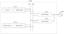
Referring to fig. 1, a schematic structural diagram of a photovoltaic system provided in the present application is shown. As shown in FIG. 1, photovoltaic system 100 includes a DC BUS BUS (corresponding to positive DC BUS BUS + and negative DC BUS BUS-in FIG. 1), and various power supply units connected in parallel to the DC BUS BUS, for example, each power supply unit may include power supply units 111, …, power supply unit 11n 1 Or power supply units 121, …, power supply unit 12n 2 ,n 1 Is an integer greater than or equal to 2, n 2 Is an integer greater than or equal to 1. When the respective power supply units include the power supply units 111, …, the power supply unit 11n 1 In this case, the photovoltaic system 100 may implement the power supply units 111, …, the power supply unit 11n 1 Reasonably distributing the load among the devices; when the respective power supply units include the power supply units 121, …, the power supply unit 12n 2 And n is 2 When the number is greater than or equal to 2, the photovoltaic system 100 may implement the power supply units 121 and … and the power supply unit 12n 2 The load between the two is reasonably distributed.
Among them, power supply units 111, …, and power supply unit 11n 1 The direct current power supply can be a photovoltaic string, and at the moment, the DC/DC converter can perform direct current conversion on electric energy of the photovoltaic string and then supply the electric energy to the direct current bus so as to realize power supply of the direct current bus; the direct current power supply can also be an energy storage battery pack string, and at the moment, the DC/DC converter can perform direct current conversion on electric energy of the direct current bus and then supply the electric energy to the energy storage battery pack string, so that the energy storage battery pack string is charged. The photovoltaic group string can comprise a plurality of photovoltaic modules connected in series and/or in parallel, and each photovoltaic module is a direct-current power supply formed by packaging solar cells in series and parallel and used for converting solar energy into electric energy. The energy storage battery string may comprise a plurality of energy storage batteries connected in series and/or in parallel. The power supply units 121, …,power supply unit 12n 2 The direct current on the direct current bus is converted into alternating current meeting the power consumption requirement of a load through inversion, or the direct current on the direct current bus is converted into the alternating current meeting the requirement of a commercial power grid through inversion. In an alternative embodiment, the power supply units 121, …, the power supply unit 12n 2 The output terminal of the power supply can be connected to a step-up transformer (not shown) and then to the power grid 200, which depends on the specific application environment and is not limited herein. The photovoltaic system 100 may output the inverted ac power to a load or a power grid 200.
In some possible embodiments, the photovoltaic system 100 further includes a system control unit (not shown) for connecting the power supply units 111 and … and the power supply unit 11n 1 Or with the supply units 121, …, and the supply unit 12n 2 Performs communication to acquire the power supply units 111, …, and the power supply unit 11n by communication 1 Or with the supply units 121, …, and the supply unit 12n 2 Power supply state parameter of (1). The system control unit may be a separate device, or may be integrated in other devices of the photovoltaic system 100, such as the power supply units 111, …, and the power supply unit 11n 1 Or in the power supply units 121, …, and the power supply unit 12n 2 To any of the power supply units. The system control unit communicates with the power supply unit through wireless communication (such as WiFi, Lora, Zig bee, etc.) or PLC communication.
The following are to realize the power supply units 111, …, and the power supply unit 11n 1 The reasonable distribution of load between is illustrated. The system control unit (not shown) in the photovoltaic system 100 is based on the power supply units 111, …, and the power supply unit 11n 1 Determines the power supply unit 111, …, and the power supply unit 11n 1 And to the power supply units 111, …, and the power supply unit 11n, respectively 1 Transmitting a bus supply current correction instruction, power supply units 111, …, and power supply unit 11n 1 Each power supply unit in the group is modified according to the received bus supply currentAnd instructing, and adjusting the bus power supply current value between the direct current bus and the direct current bus to be the respective reference power supply current value. Here, in n 2 Is an integer greater than or equal to 2, the power supply units 121, …, and the power supply unit 12n are implemented 2 The implementation of reasonable load distribution between the power supply units 111 and … can be referred to as the implementation of the power supply unit 11n 1 And the load between the two is reasonably distributed.
According to the power supply current control mode of the photovoltaic system, under the condition that the output power of the photovoltaic system is greater than the system output power threshold value, the power supply current values of the power supply units can be distributed according to the current actual power supply capacity of the power supply units connected in parallel to the direct-current bus, so that reasonable load distribution among the power supply units is achieved, the service lives of the power supply units are prolonged, and the operation and maintenance cost of the photovoltaic system is reduced.
In an optional embodiment, the technical scheme provided by the present application may be applied to a pure-light photovoltaic scene, and then the photovoltaic system provided by the present application is a pure-light system. Fig. 2 is a schematic structural diagram of a pure optical system provided in the present application. As shown in fig. 2, power supply units 111, …, power supply unit 11n 1 Can be composed of a DC/DC converter and a photovoltaic string connected with the input end of the DC/DC converter, power supply units 121, … and a power supply unit 12n 2 May be both DC/AC converters with their inputs connected to the DC BUS. In an optional implementation scenario, the pure light system 100 may also be applied in a scenario of an uninterruptible power supply, that is, an energy storage battery, such as a nickel-cadmium battery, a nickel-hydrogen battery, a lithium ion battery, a lithium polymer battery, and the like, may be disposed between the DC/AC converter and the power grid 200.
In another optional embodiment, the technical scheme provided by the present application may be applied to a pure storage photovoltaic scene, and the photovoltaic system provided by the present application is a pure storage system. Referring to fig. 3, it is a schematic structural diagram of the pure storage system provided in the present application. As shown in fig. 3, power supply units 111, …, power supply unit 11n 1 May each be formed by a DC/DC converter and a series of energy storage cells connected to the input of the DC/DC converter, a power supply unit 121, …, and a power supply unit12n 2 May be a DC/AC converter with an input connected to the DC BUS. In an optional implementation scenario, the pure storage system 100 may also be applied in a scenario of an uninterruptible power supply, that is, an energy storage battery, for example, a nickel-cadmium battery, a nickel-hydrogen battery, a lithium ion battery, a lithium polymer battery, or the like, may be disposed between the DC/AC converter and the power grid 200.
In yet another optional embodiment, the technical solution provided by the present application may be applied to a photovoltaic scene of a light storage, and then the photovoltaic system provided by the present application is a light storage system. Fig. 4 is a schematic structural diagram of the light storage system provided in the present application. As shown in fig. 4, power supply units 111, …, power supply unit 11n 1 Comprising both a power supply unit consisting of a DC/DC converter and a photovoltaic string connected to the input of the DC/DC converter and a power supply unit consisting of a DC/DC converter and an energy storage battery string connected to the input of the DC/DC converter, a power supply unit 121, …, and a power supply unit 12n 2 May be a DC/AC converter with an input connected to the DC BUS. In an optional implementation scenario, the light storage system 100 may also be applied to a scenario of an uninterruptible power supply, that is, an energy storage battery, such as a nickel-cadmium battery, a nickel-hydrogen battery, a lithium ion battery, a lithium polymer battery, or the like, may be disposed between the DC/AC converter and the power grid 200.
Referring now to FIG. 1, n 2 For example, integers greater than or equal to 2, specific implementations of the photovoltaic system for controlling the supply current are described.
In some possible embodiments, the system control unit, in case it is determined that the current output power of the photovoltaic system is greater than the system output power threshold, supplies the respective power supply units (corresponding to power supply units 111, …, power supply unit 11n in fig. 1) connected in parallel to the dc BUS 1 Or power supply units 12n corresponding to power supply units 121, … in fig. 1 2 ) And sending a power supply parameter acquisition instruction. And each power supply unit sends respective current power supply state parameters to the system control unit according to the power supply parameter acquisition instruction. The system output power threshold may be an output power threshold carried in a power limit instruction sent by a user to the photovoltaic system, that is, the systemThe output power threshold may be artificially defined.
And then, the system control unit determines the reference power supply current value of each power supply unit according to the received current power supply state parameter of each power supply unit.
In an alternative embodiment, the current power supply state parameter of each power supply unit comprises the current maximum power supply of each power supply unit.
Among them, the power supply units are the power supply units 111, … in fig. 1, and the power supply unit 11n 1 Under the condition of any power supply unit, the current maximum power supply power of the power supply unit is the current maximum output power of a DC/DC converter in the power supply unit, namely the current allowed maximum output power of the DC/DC converter; in the case where the power supply units are the power supply units 121, … in fig. 1, the power supply unit 12n 2 In the case of any power supply unit, the current maximum power supply of the power supply unit is the current maximum input power of the DC/AC converter in the power supply unit, that is, the maximum input power currently allowed by the DC/AC converter.
The system control unit can obtain a system output power threshold value and direct-current bus voltage, and determines the quotient of the system output power threshold value and the direct-current bus voltage as the total current of the photovoltaic system after power limitation.
The system control unit can determine the current maximum power supply ratio of the ith power supply unit as P according to the current maximum power supply of each power supply unit Mi /(P M1 +…+P Mi +…+P Mn ) Wherein P is M1 ,…,P Mi ,…,P Mn Current maximum power supply power of the 1 st power supply unit, …, current maximum power supply power of the ith power supply unit, …, current maximum power supply power of the nth power supply unit, i being an integer greater than or equal to 1 and less than or equal to n, respectively.
For example, suppose that the respective power supply units are the
power supply units 111, … and the
power supply unit 11n in fig. 1
1 Then the
power supply unit 11n
1 Has a current maximum power supply ratio of
Wherein, P
OM1 ,…,
Current maximum output power of the DC/DC converter in the
power supply unit 111, …, respectively, the
power supply unit 11n
1 The current maximum output power of the medium DC/DC converter.
As another example, suppose that the respective power supply units are the
power supply units 121, … and the power supply unit 12n in fig. 1
2 Then a power supply unit 12n
2 Has a current maximum power supply ratio of
Wherein, P
IM1 ,…,
The current maximum input power of the DC/AC converter in the
power supply unit 121, …, respectively, the power supply unit 12n
2 The current maximum input power of the medium DC/AC converter.
Further, the current power supply state parameters of each power supply unit also include current device operating condition parameters of each power supply unit.
The system control unit can also determine the current corrected power supply power of each power supply unit based on the current equipment working condition parameters and the current maximum power supply power of each power supply unit, determine the current corrected power supply power occupation ratio of the current corrected power supply power of each power supply unit in the sum of the current corrected power supply powers of at least two power supply units based on the current corrected power supply power of each power supply unit, and determine the current corrected power supply power occupation ratio of each power supply unit as the current maximum power supply power occupation ratio of each power supply unit.
Wherein, the power supply units are the power supply units 111, … in fig. 1, and the power supply unit 11n 1 Under the condition of any power supply unit, the current equipment working condition parameter of the power supply unit can be the current equipment working condition parameter of a DC/DC converter in the power supply unit; in the case where the power supply units are the power supply units 121, … in fig. 1, the power supply unit 12n 2 In the case of any one of the power supply units, of the power supply unitThe current equipment operating condition parameter may be a current equipment operating condition parameter of a DC/AC converter in the power supply unit. The current equipment working condition parameters comprise at least one of current equipment temperature, current equipment current stress or current equipment voltage stress, wherein the current equipment current stress is the ratio of the current working voltage of the equipment to the rated voltage, and the current equipment current stress is the ratio of the current working current of the equipment to the rated current. Illustratively, the current device voltage stress of the power supply unit 111 is a ratio of a current output voltage of the DC/DC converter in the power supply unit 111 to a rated voltage, and the current device current stress of the power supply unit 111 is a ratio of a current output current of the DC/DC converter in the power supply unit 111 to a rated current.
The following description will take the current device operating condition parameters as the current device temperature.
Specifically, the system control unit may obtain power attenuation coefficients corresponding to the current device temperatures of the power supply units by looking up a table, determine a product of the current maximum power supply power of each power supply unit and the power attenuation coefficient corresponding to the current device temperature of the system control unit as the current corrected power supply power of each power supply unit, calculate the current corrected power supply power ratio of each power supply unit according to the current corrected power supply power of each power supply unit, and determine the current corrected power supply power ratio of each power supply unit as the current maximum power supply power ratio of each power supply unit. The relationship between the power attenuation coefficient of the power supply unit and the device temperature may be that the power attenuation coefficient of the power supply unit decreases with the increase of the device temperature of the power supply unit, or may be that different device temperature intervals correspond to power attenuation coefficients of different values, which is not specifically limited herein. Except that the current device operating condition parameter is the current device temperature, other conditions can be obtained by the same process when the current device operating condition parameter is the current device temperature, and the description is omitted here.
It can be understood that the current maximum power supply power of the power supply units with overhigh device temperature, overlarge device current stress or overlarge device voltage stress can be reduced through the power attenuation coefficient, and the service life of each power supply unit is further prolonged.
And then, the system control unit determines the product of the total current after the power limitation of the photovoltaic system and the maximum power supply ratio of each power supply unit as a reference power supply current value of each power supply unit.
It can be understood that, in this embodiment, the reference power supply current value of each power supply unit is obtained by calculation according to the current maximum power supply power ratio of each power supply unit and the total current after the power limitation of the photovoltaic system, so that not only can the reasonable distribution of the load be realized according to the current actual power supply capacity of each power supply unit, but also the balanced distribution of the power supply power of each power supply unit can be realized, the service life of each power supply unit is prolonged, and the operation and maintenance cost of the photovoltaic system is reduced. And the output power of the photovoltaic system can be ensured to be smaller than the system output power threshold value after each power supply unit performs feedback regulation on the respective power supply current value according to the respective reference power supply current value.
In another alternative embodiment, the current power supply state parameter of each power supply unit comprises a current maximum power supply and a current power supply current of each power supply unit.
Among them, the power supply units are the power supply units 111, … in fig. 1, and the power supply unit 11n 1 Under the condition of any power supply unit, the current maximum power supply power and the current power supply current of the power supply unit are respectively the current maximum output power of a DC/DC converter in the power supply unit and the current output current of the DC/DC converter, and the current input current I of the DC/DC converter acquired by the DC/DC converter in Current input voltage U in And the present output voltage U out (namely the direct current bus voltage) and calculating to obtain the current output current I of the DC/DC converter out =U in *I in /U out (ii) a In the case where the power supply units are the power supply units 121, … in fig. 1, the power supply unit 12n 2 Under the condition of any one power supply unit, the current maximum power supply power and the current power supply current of the power supply unit are respectively the current maximum input power of a DC/AC converter and the current input current of the DC/AC converter in the power supply unit, and the current output current I of the DC/AC converter acquired by the DC/AC converter out Current input voltage U in (i.e. the dc bus voltage) and the present output voltage U out Calculating the present input current I of the DC/AC converter in =U out *I out /U in 。
The system control unit can calculate the current maximum power supply ratio of the current maximum power supply power of each power supply unit in the sum of the current maximum power supply powers of at least two power supply units according to the current maximum power supply power of each power supply unit connected in parallel to the direct current bus.
Further, the current power supply state parameters of each power supply unit also include current device operating condition parameters of each power supply unit.
The system control unit can also determine the current corrected power supply power of each power supply unit based on the current equipment working condition parameters and the current maximum power supply power of each power supply unit, determine the current corrected power supply power occupation ratio of the current corrected power supply power of each power supply unit in the sum of the current corrected power supply powers of at least two power supply units based on the current corrected power supply power of each power supply unit, and determine the current corrected power supply power occupation ratio of each power supply unit as the current maximum power supply power occupation ratio of each power supply unit.
And then, the system control unit determines the product of the sum of the current power supply currents of the power supply units and the current maximum power supply ratio of the power supply units as the reference power supply current value of each power supply unit.
For example, suppose that the respective power supply units are the
power supply units 111, … and the
power supply unit 11n in fig. 1
1 Then the
power supply unit 11n
1 Has a reference supply current value of
Wherein,
to
power supply unit 11n
1 Current maximum supply power ratio of
o1 ,…,
Current output current of the DC/DC converter in the
power supply unit 111, …, respectively, the
power supply unit 11n
1 The present output current of the medium DC/DC converter.
As another example, suppose that the respective power supply units are the
power supply units 121, … and the power supply unit 12n in fig. 1
2 Then a power supply unit 12n
2 Is a reference supply current value of
Wherein,
to a power supply unit 12n
2 Current maximum supply power ratio of
I1 ,…,I
In2 Current input current of the DC/AC converter in the
power supply unit 121, …, respectively, the power supply unit 12n
2 The present input current of the medium DC/AC converter.
In a further alternative embodiment, the current power supply state parameter of each power supply unit comprises a current power supply and a current power supply capability of each power supply unit.
The current power supply capability of the power supply unit includes a maximum power supply currently allowed by the power supply unit, that is, a current maximum power supply. In the case where the power supply units are the power supply units 111, … in fig. 1, the power supply unit 11n 1 Under the condition of any power supply unit, the current maximum power supply power of the power supply unit is the current maximum output power of a DC/DC converter in the power supply unit; in the case where the power supply units are the power supply units 121, … in fig. 1, the power supply unit 12n 2 In the case of any one of the power supply units, the current maximum supply power of the power supply unit is the current maximum input power of the DC/AC converter in the power supply unit.
The system control unit may calculate a current maximum power supply power ratio of the current maximum power supply power of each power supply unit in a sum of current maximum power supply powers of the at least two power supply units, according to the current maximum power supply power of each power supply unit.
Further, the current power supply capability of each power supply unit further includes a current device operating condition parameter of each power supply unit.
The system control unit can also determine the current corrected power supply power of each power supply unit based on the current equipment working condition parameters and the current maximum power supply power of each power supply unit, determine the current corrected power supply power occupation ratio of the current corrected power supply power of each power supply unit in the sum of the current corrected power supply powers of at least two power supply units based on the current corrected power supply power of each power supply unit, and determine the current corrected power supply power occupation ratio of each power supply unit as the current maximum power supply power occupation ratio of each power supply unit.
And then, the system control unit determines the product of the sum of the current power supply currents of the power supply units and the current maximum power supply ratio of the power supply units as the reference power supply current value of each power supply unit.
It can be understood that, in this embodiment, the current power supply power of each power supply unit can be reasonably distributed according to the current actual power supply capability of each power supply unit, so that power supply power balance among each power supply unit is realized, and one or a part of the power supply units in each power supply unit is prevented from working in a limit power supply state (that is, the power supply units supply power with power supply power exceeding the maximum power supply power that the power supply units can currently bear), so that the service lives of the power supply units are prolonged, and the operation and maintenance cost of the photovoltaic system is reduced.
And then, the system control unit adjusts the current power supply of each power supply unit according to the reference power supply current value of each power supply unit, so that the current power supply of each power supply unit is the reference power supply of each power supply unit, wherein the reference power supply of each power supply unit is the product of the reference power supply current of each power supply unit and the direct-current bus voltage. Because the power supply voltages (i.e., the dc bus voltages) between each power supply unit connected in parallel to the dc bus and the dc bus are all equal, when the current power supply of each power supply unit is adjusted to the reference power supply of each power supply unit, only the power supply current value between each power supply unit and the dc bus needs to be adjusted to the reference power supply current value of each power supply unit.
In some possible embodiments, the system control unit sends a power supply power correction instruction to each power supply unit, and the power supply unit adjusts a power supply current value between the power supply unit and the dc bus to be a reference power supply current value of the power supply unit according to the received power supply power correction instruction, so that the current power supply power of the power supply unit is the reference power supply power of the power supply unit.
In an alternative embodiment, the supply power modification command comprises a reference supply current value of the power supply unit.
When the current power supply state parameter of the power supply unit includes the current power supply current of the power supply unit, the power supply unit may use a difference value between a reference power supply current value and the current power supply current value of the power supply unit as an input parameter of a proportional-integral (PI) control algorithm, determine a control correction amount of the power supply unit, and determine a sum of the control correction amount and an initial bus reference voltage of the power supply unit as a target bus reference voltage of the power supply unit. Further, the power supply unit may further determine a virtual impedance value corresponding to the current supply current of the power supply unit as a virtual impedance value of the power supply unit, determine a product between the current supply current of the power supply unit and the virtual impedance value as a voltage correction amount of the power supply unit, and determine a sum of the voltage correction amount of the power supply unit, the control correction amount, and the initial bus reference voltage as a target bus reference voltage of the power supply unit.
Among them, the power supply units are the power supply units 111, … in fig. 1, and the power supply unit 11n 1 Under the condition of any power supply unit, the current power supply current of the power supply unit is the current output current of a DC/DC converter in the power supply unit; in the case where the power supply units are the power supply units 121, … in fig. 1, the power supply unit 12n 2 In the case of any one of the power supply units, the present supply current of the power supply unit is the present input current of the DC/AC converter in the power supply unit. The virtual impedance value may be a fixed value or may be an non-positive number that increases as the supply current or the supply power of the power supply unit increases.
For ease of understanding, reference is made to FIG. 5 for the virtual impedance versus initial bus reference provided by the present applicationThe voltage is used to generate a graph of droop characteristics. As shown in FIG. 5, the virtual impedance value at the left part of FIG. 5 is a fixed value, i.e., the slope-R of a straight line, which represents the bus reference voltage U of the power supply unit as the supply current I of the power supply unit increases
ref The number of the grooves is continuously reduced, wherein,
is the initial bus reference voltage of the power supply unit. The right part of fig. 5 corresponds to the virtual impedance value being a non-positive number that increases with increasing supply current or supply power of the power supply unit, i.e. the virtual impedance value for the supply current I is the slope r (I) of the tangent of the supply current I at a curve that represents the bus reference voltage U of the power supply unit with increasing supply current I of the power supply unit
ref The number of the grooves is continuously reduced, wherein,
it can be understood that, in this embodiment, the power supply unit may determine its own control correction amount according to its own current power supply current value and the reference power supply current value of the power supply unit included in the power supply power correction instruction, and correct its own initial bus reference voltage according to its own control correction amount, so as to implement power supply according to its own current actual power supply capability, and further, the power supply unit may further correct its own initial bus reference voltage according to the droop characteristic of the virtual impedance, so as to ensure that the power supply unit is in a stable power supply state. In addition, in this embodiment, the target bus reference voltage of the power supply unit is calculated by the power supply unit according to the reference power supply current value of the power supply unit sent by the system control unit, which can reduce the calculation amount of the system control unit and improve the processing efficiency of the system control unit.
In another alternative embodiment, the power supply power modification command includes a control modification of the power supply unit.
Before the system control unit sends the power supply power correction instruction to each power supply unit, the system control unit may use a difference between a reference power supply current value of each power supply unit and a corresponding current power supply current value as an input parameter of a PI control algorithm, respectively, determine a control correction amount of each power supply unit, and send the power supply power correction instruction to each power supply unit.
And each power supply unit receives the power supply power correction command and determines the sum of the initial bus reference voltage and the control correction quantity of the power supply unit contained in the power supply power correction command as the target bus reference voltage. Further, the power supply unit may further determine a virtual impedance value corresponding to a current power supply current of the power supply unit as a virtual impedance value of the power supply unit, determine a product between the power supply current of the power supply unit and the virtual impedance value as a voltage correction amount of the power supply unit, and determine a sum of the voltage correction amount of the power supply unit, the control correction amount, and the initial bus reference voltage as a target bus reference voltage of the power supply unit.
In yet another alternative embodiment, the power supply power correction command includes a target bus reference voltage for the power supply unit.
Before the system control unit sends a power supply power correction instruction to each power supply unit, the system control unit may use a difference between a reference power supply current value of each power supply unit and a corresponding current power supply current value as an input parameter of a PI control algorithm, respectively, determine a control correction amount of each power supply unit, and determine a sum of the control correction amount of each power supply unit and an initial bus reference voltage as a target bus reference voltage of each power supply unit. Further, the system control unit may further determine a virtual impedance value corresponding to the current power supply current of each power supply unit as a virtual impedance value of each power supply unit, determine a product between the power supply current of each power supply unit and the virtual impedance value as a voltage correction amount of each power supply unit, determine a sum of the voltage correction amount, the control correction amount, and the initial bus reference voltage of each power supply unit as a target bus reference voltage of each power supply unit, and send a power supply power correction instruction including the target bus reference voltage to each power supply unit.
It can be understood that the power supply power correction instruction provided by the present application may include any one of a reference power supply current value of the power supply unit, a control correction amount, and a target bus reference voltage, and may improve the applicability of the photovoltaic system.
Further, the system control unit sends a power supply power correction instruction to each power supply unit under the condition that the current output power of the photovoltaic system is determined to be smaller than or equal to the system output power threshold value. And each power supply unit determines the respective initial bus reference voltage as the respective target bus reference voltage according to the power supply power correction instruction.
Then, each power supply unit may output a voltage difference between the respective target bus reference voltage and the dc bus voltage to a respective switching power supply control circuit (e.g., a pulse width modulation circuit), and the switching power supply control circuit outputs a PWM wave according to the input voltage difference, and outputs the PWM wave to a switching circuit of the power supply unit, so as to control a turn-on frequency of the switching circuit, and further control a power supply current value between each power supply unit and the dc bus to be a respective reference power supply current value.
Among them, when the respective power supply units are the power supply units 111, … in fig. 1, the power supply unit 11n 1 When the current is detected, the power supply current value between each power supply unit and the direct current bus, namely the output current value of the DC/DC converter in each power supply unit; when the respective power supply units are the power supply units 121, … in fig. 1, the power supply unit 12n 2 The value of the power supply current between each power supply unit and the DC bus, i.e., the value of the input current of the DC/AC converter in each power supply unit.
It should be noted that, in the embodiment of the present application, the system control unit may be a device independent from each power supply unit in the photovoltaic system, or may be a DC/DC converter or a DC/AC converter included in any one of the power supply units connected in parallel to the DC bus.
In the application, under the condition that the output power of the photovoltaic system is greater than the system output power threshold, the system control unit can distribute the power supply current values of the power supply units according to the current actual power supply capacity of the power supply units connected in parallel to the direct-current bus, so that reasonable load distribution among the power supply units is realized (namely, power supply power balance among the power supply units is realized), one or part of the power supply units in the power supply units is prevented from working in a limit power supply state, the service lives of the power supply units are prolonged, and the operation and maintenance cost of the photovoltaic system is reduced. In addition, under the condition that the output power of the photovoltaic system is smaller than or equal to the system output power threshold, the system control unit does not perform load balancing on each power supply unit any more, each power supply unit determines the respective initial bus reference voltage as the respective target bus reference voltage, and adjusts the power supply current value between each power supply unit and the direct current bus according to the respective target bus reference voltage, so that each power supply unit can be guaranteed to supply power with the current maximum power supply, and the power generation amount of the photovoltaic system is improved.
Referring now to FIG. 1, n 2 For example, 1 describes a specific implementation manner of controlling the supply current of the photovoltaic system.
In some possible embodiments, the DC/AC converter supplies power to the power supply units 111, … connected in parallel to the DC BUS, and to the power supply unit 11n, in case it is determined that the current output power of the photovoltaic system is greater than the system output power threshold value 1 And the medium DC/DC converter sends an output parameter acquisition instruction. Power supply units 111, …, and power supply unit 11n 1 And the intermediate DC/DC converter sends respective current output state parameters to the DC/AC converter according to the output parameter acquisition instruction.
The DC/AC converter receives the power supply units 111, … and the power supply unit 11n 1 The current output state parameter of the DC/DC converter in each power supply unit determines the reference output current value of the DC/DC converter in each power supply unit.
In an alternative embodiment, the current output state parameter of the DC/DC converter in each power supply unit comprises the current maximum output power of the DC/DC converter in each power supply unit.
The DC/AC converter can obtain a system output power threshold value and a direct current bus voltage, and the quotient of the system output power threshold value and the direct current bus voltage is determined as the total current of the photovoltaic system after power limitation.
The DC/AC converter may calculate the current maximum output power of the DC/DC converter in each power supply unit according to the current maximum output power of the DC/DC converter in each power supply unit, and obtain the current maximum output power proportion of the DC/DC converter in each power supply unit from the proportion in the sum of the current maximum output powers of all DC/DC converters.
Further, the current output state parameter of the DC/DC converter in each power supply unit further includes the current device operating condition parameter of the DC/DC converter in each power supply unit.
Wherein the current device operating condition parameter includes at least one of a current device temperature, a current device current stress, or a current device voltage stress.
The DC/AC converter can also determine the current corrected supply power of each DC/DC converter based on the current equipment working condition parameter and the current maximum supply power of each DC/DC converter, determine the current corrected supply power ratio of the current corrected supply power of each DC/DC converter in the sum of the current corrected supply powers of at least two DC/DC converters based on the current corrected supply power of each DC/DC converter, and determine the current corrected supply power ratio of each DC/DC converter as the current maximum output power ratio of each DC/DC converter.
It can be understood that the DC/AC converter can reduce the current maximum output power of the DC/DC converter with too high device temperature, too high device current stress or too high device voltage stress through the power attenuation coefficient, thereby prolonging the service life of each DC/DC converter.
And then, the DC/AC converter determines the product of the total current after the photovoltaic system is limited in power and the ratio of the maximum output power of each DC/DC converter as the reference output current value of each DC/DC converter.
It can be understood that, in the embodiment, the DC/AC converter calculates the reference output current value of each DC/DC converter according to the current maximum output power ratio of each DC/DC converter and the total current after the power limitation of the photovoltaic system, so that not only can the reasonable distribution of the load be realized according to the current actual output capability of each DC/DC converter, that is, the balanced distribution of the output power of each DC/DC converter be realized, the service life of each DC/DC converter is prolonged, and the operation and maintenance cost of the photovoltaic system is reduced. And the output power of the photovoltaic system is smaller than the system output power threshold value after the DC/DC converters perform feedback regulation on the respective output current values according to the respective reference output current values.
In another alternative embodiment, the present output state parameter of the DC/DC converter in each power supply unit comprises the present maximum output power and the present output current of the DC/DC converter of each power supply unit.
The DC/AC converter can calculate the current maximum output power ratio of the current maximum output power of each DC/DC converter in the sum of the current maximum output powers of at least two DC/DC converters according to the current maximum output power of each DC/DC converter connected in parallel with the direct current bus.
Further, the current output state parameter of the DC/DC converter in each power supply unit further includes the current device operating condition parameter of the DC/DC converter in each power supply unit.
The DC/AC converter can also determine the current corrected output power of each DC/DC converter based on the current equipment working condition parameter and the current maximum output power of each DC/DC converter, determine the current corrected output power proportion of the current corrected output power of each DC/DC converter in the sum of the current corrected output powers of at least two DC/DC converters based on the current corrected output power of each DC/DC converter, and determine the current corrected output power proportion of each DC/DC converter as the current maximum output power proportion of each DC/DC converter.
Then, the DC/AC converter determines the product of the sum of the present output currents of the respective DC/DC converters and the present maximum output power ratio of the respective DC/DC converters as the reference output current value of the respective DC/DC converters.
In a further alternative embodiment, the current output state parameters of the DC/DC converters in the respective power supply units comprise the current output power and the current output capability of the DC/DC converters in the respective power supply units.
The current output capability of the DC/DC converter in the power supply unit includes a maximum output power currently allowed by the DC/DC converter in the power supply unit, that is, a current maximum output power of the DC/DC converter.
The DC/AC converter may calculate a current maximum output power ratio of the current maximum output power of each DC/DC converter among the sums of the current maximum output powers of the at least two DC/DC converters, according to the current maximum output power of each DC/DC converter.
Further, the current output capability of the DC/DC converter in each power supply unit further includes the current device operating condition parameters of the DC/DC converter in each power supply unit.
The DC/AC converter can also determine the current corrected output power of each DC/DC converter based on the current equipment working condition parameter and the current maximum output power of each DC/DC converter, determine the current corrected output power ratio of the current corrected output power of each DC/DC converter in the sum of the current corrected output powers of at least two DC/DC converters based on the current corrected output power of each DC/DC converter, and determine the current corrected output power ratio of each DC/DC converter as the current maximum output power ratio of each DC/DC converter.
Then, the DC/AC converter determines the product of the sum of the present output currents of the respective DC/DC converters and the present maximum output power ratio of the respective DC/DC converters as the reference output current value of the respective DC/DC converters.
It can be understood that, in the DC/AC converter of this embodiment, the current output power of each DC/DC converter can be reasonably distributed according to the current actual output capability of each DC/DC converter, so as to achieve output power balance among each DC/DC converter, and prevent one or a part of the DC/DC converters in each DC/DC converter from operating in the limit power supply state (that is, the DC/DC converter operates at an output power exceeding the maximum output power that the DC/DC converter can currently bear), thereby prolonging the service life of each DC/DC converter, and reducing the operation and maintenance cost of the photovoltaic system.
Then, the DC/AC converters each output a current value according to the reference output current value of each DC/DC converterAnd adjusting the current output power of each DC/DC converter so that the current output power of each DC/DC converter is the reference output power of each DC/DC converter, wherein the reference output power of each DC/DC converter is the product of the reference output current of each DC/DC converter and the direct-current bus voltage. Since the output voltages (i.e., the DC bus voltages) between the DC/DC converters connected in parallel to the DC bus are all equal, when the current output power of each DC/DC converter is adjusted to be the reference output power of each DC/DC converter, only the output current value between each DC/DC converter and the DC bus needs to be adjusted to be the reference output current value of each DC/DC converter. Here, please refer to n for specific implementation manner of the DC/AC converter adjusting the current output power of each DC/DC converter according to the reference output current value of each DC/DC converter 2 The description of the corresponding parts in the embodiments that are integers greater than or equal to 2 is omitted here for brevity.
In the application, under the condition that the output power of the photovoltaic system is greater than the system output power threshold, the DC/AC converters can distribute the output current values of the DC/DC converters according to the current actual output capabilities of the DC/DC converters connected in parallel to the DC bus, so that the reasonable load distribution among the DC/DC converters (i.e., the output power balance among the DC/DC converters) is realized, one or part of the DC/DC converters in each DC/DC converter is prevented from working in a limit power supply state, the service life of each DC/DC converter is prolonged, and the operation and maintenance cost of the photovoltaic system is reduced. In addition, under the condition that the output power of the photovoltaic system is smaller than or equal to the system output power threshold, the DC/AC converters do not perform load balancing on the DC/DC converters any more, the DC/DC converters determine respective initial bus reference voltages as respective target bus reference voltages, and output current values between the DC/DC converters and the direct-current bus are adjusted according to the respective target bus reference voltages, so that the DC/DC converters can be ensured to output at the current maximum output power, and the power generation amount of the photovoltaic system is improved.
The following description refers to the photovoltaic system (n) of fig. 1 2 Is an integer greater than or equal to 2) A specific embodiment of a method for controlling a supply current of a photovoltaic system is described.
Referring to fig. 6, a flow chart of a method for controlling a supply current of a photovoltaic system provided in the present application is shown. The method for controlling the power supply current of the photovoltaic system provided by the embodiment of the application can comprise the following steps:
s101, obtaining current power supply state parameters of each power supply unit in at least two power supply units, and determining reference power supply current values of each power supply unit according to the current power supply state parameters of each power supply unit.
In a possible embodiment, the supply current control device supplies the respective power supply units (corresponding to power supply units 111, … in fig. 1, power supply unit 11 n) connected in parallel to the dc BUS in the case of determining that the present output power of the photovoltaic system is greater than the system output power threshold value 1 Or corresponding to the supply units 121, … in fig. 1, the supply unit 12n 2 ) And sending a power supply parameter acquisition instruction. And each power supply unit sends respective current power supply state parameters to the power supply current control device according to the received power supply parameter acquisition instruction.
In an alternative embodiment, the current power supply state parameter of each power supply unit comprises the current maximum power supply of each power supply unit.
The power supply current control device can obtain a system output power threshold value and direct current bus voltage, and determines a quotient between the system output power threshold value and the direct current bus voltage as the total current of the photovoltaic system after power limitation. And determining the product of the total current after the power limitation of the photovoltaic system and the current maximum power supply power ratio of each power supply unit as the reference power supply current value of each power supply unit.
In another alternative embodiment, the current power supply state parameter of each power supply unit comprises a current maximum power supply and a current power supply current of each power supply unit.
The power supply current control device can determine the product of the sum of the current power supply currents of the power supply units and the current maximum power supply ratio of the power supply units as the reference power supply current value of each power supply unit.
In yet another alternative embodiment, the current power supply state parameters of each power supply unit include the current power supply and the current power supply capability of each power supply unit.
The current power supply capability of the power supply unit includes a maximum power supply currently allowed by the power supply unit, that is, a current maximum power supply.
The supply current control device may calculate a present maximum supply power ratio of the present maximum supply power of each power supply unit among a sum of the present maximum supply powers of the at least two power supply units, according to the present maximum supply power of each power supply unit.
In the above three optional embodiments, the current maximum power supply ratio of each power supply unit may be determined by the power supply current control device directly according to the current maximum power supply of each power supply unit, or may be determined by the power supply current control device according to the current device operating condition parameter of each power supply device, when the current power supply state parameter of each power supply unit further includes the current device operating condition parameter of each power supply unit, or the current power supply capability of each power supply unit further includes the current device operating condition parameter of each power supply unit, correcting the current maximum power supply of each power supply unit by the power supply current control device according to the current device operating condition parameter of each power supply device, and determining the current maximum power supply ratio of each power supply unit according to the current corrected power supply ratio of each power supply unit. The current equipment working condition parameter comprises at least one of current equipment temperature, current equipment current stress or current equipment voltage stress.
It can be understood that, by modifying the current maximum power supply of the power supply unit according to the current device operating condition parameter of the power supply unit, at least one of the conditions of over-high device temperature, over-high device current stress or over-high device voltage stress can be avoided, and the service life of the power supply unit is prolonged.
And S102, adjusting the current power supply of each power supply unit according to the reference power supply current value of each power supply unit.
In some possible embodiments, the power supply current control device sends a power supply power correction instruction to each power supply unit, and the power supply unit adjusts a power supply current value between the power supply unit and the dc bus to be a reference power supply current value of the power supply unit according to the received power supply power correction instruction, so that the current power supply power of the power supply unit is the reference power supply power of the power supply unit.
In an alternative embodiment, the supply power modification command comprises a reference supply current value of the supply unit.
In an alternative embodiment, the power supply power modification command includes a control modification of the power supply unit.
Before the power supply current control device sends the power supply power correction instruction to each power supply unit, the power supply current control device can respectively use the difference value between the reference power supply current value and the current power supply current value of each power supply unit as an input parameter of a PI control algorithm, decide the control correction amount of each power supply unit, and send the power supply power correction instruction to each power supply unit.
In yet another alternative embodiment, the power supply power modification instruction includes a target bus reference voltage for the power supply unit.
Before the power supply current control device sends the power supply power correction instruction to each power supply unit, the power supply current control device may use a difference value between a reference power supply current value and a current power supply current value of each power supply unit as an input parameter of a PI control algorithm, determine a control correction amount of each power supply unit, and determine a sum of the control correction amount of each power supply unit and an initial bus reference voltage as a target bus reference voltage of each power supply unit. Further, the power supply current control device may determine a virtual impedance value corresponding to the current power supply current of each power supply unit as a virtual impedance value of each power supply unit, determine a product between the power supply current of each power supply unit and the virtual impedance value as a voltage correction amount of each power supply unit, determine a sum of the voltage correction amount, the control correction amount, and the initial bus reference voltage of each power supply unit as a target bus reference voltage of each power supply unit, and send a power supply power correction instruction including the target bus reference voltage to each power supply unit.
It can be understood that the power supply power correction instruction provided by the present application may include any one of a reference power supply current value of the power supply unit, a control correction amount, and a target bus reference voltage, and may improve applicability of the power supply current control method.
In the embodiment of the present application, the supply current control device may be a device independent from each power supply unit in the photovoltaic system, or may be a DC/DC converter or a DC/AC converter included in any one of the power supply units connected in parallel to the DC bus.
In the embodiment of the application, the power supply current control device can distribute the power supply current values of the power supply units according to the current actual power supply capacities of the power supply units connected in parallel to the direct-current bus under the condition that the output power of the photovoltaic system is greater than the system output power threshold (namely, the power supply power balance among the power supply units is realized), so that one or part of the power supply units in the power supply units is prevented from working in a limit power supply state, the reasonable distribution of loads among the power supply units is realized, the service lives of the power supply units are prolonged, and the operation and maintenance cost of the photovoltaic system is reduced.
The following description refers to the photovoltaic system (n) of fig. 1 2 1) the present invention is described with reference to a specific embodiment of a method for controlling a supply current of a photovoltaic system.
Referring to fig. 7, a schematic flow chart of a method for controlling a supply current of a photovoltaic system provided in the present application is shown. The method for controlling the power supply current of the photovoltaic system provided by the embodiment of the application can comprise the following steps:
s201, when the DC/AC converter is in a power limiting working mode, obtaining current output state parameters of the DC/DC converter in each power supply unit, and determining reference output current values of the DC/DC converter in each power supply unit according to the current output state parameters of the DC/DC converter in each power supply unit.
In a possible embodiment, the DC/AC converter supplies the power supply unit 11n to the power supply unit 111, … connected in parallel to the DC BUS in the event that it is determined that the current output power of the photovoltaic system is greater than the system output power threshold value 1 Intermediate DC/DC conversionAnd the device sends an output parameter acquisition instruction. Power supply units 111, …, and power supply unit 11n 1 And the medium DC/DC converter sends respective current output state parameters to the DC/AC converter according to the received output parameter acquisition instruction.
In an alternative embodiment, the current output state parameter of the DC/DC converter in each power supply unit comprises the current maximum output power of the DC/DC converter in each power supply unit.
The DC/AC converter can obtain a system output power threshold value and a direct current bus voltage, and a quotient between the system output power threshold value and the direct current bus voltage is determined as a total current after the photovoltaic system is limited in power. And determining the product of the total current after the photovoltaic system limits the power and the current maximum output power ratio of each DC/DC converter as the reference output current value of each DC/DC converter.
In another alternative embodiment, the present output state parameter of the DC/DC converter in each power supply unit comprises the present maximum output power and the present output current of the DC/DC converter of each power supply unit.
The DC/AC converter may determine a product between a sum of present output currents of the respective DC/DC converters and a present maximum output power ratio of the respective DC/DC converters as a reference output current value of the respective DC/DC converters, respectively.
In a further alternative embodiment, the current output state parameters of the DC/DC converters in the respective power supply units comprise the current output power and the current output capability of the DC/DC converters in the respective power supply units.
The current output capability of the DC/DC converter in the power supply unit includes a maximum output power currently allowed by the DC/DC converter in the power supply unit, that is, a current maximum output power of the DC/DC converter.
The DC/AC converter may calculate a current maximum output power ratio of the current maximum output power of each DC/DC converter among the sums of the current maximum output powers of the at least two DC/DC converters, according to the current maximum output power of each DC/DC converter.
In the above three alternative embodiments, the current maximum output power ratio of each DC/DC converter may be determined by the DC/AC converter directly according to the current maximum output power of each DC/DC converter, or in the case that the current output state parameter of each DC/DC converter further includes the current device operating condition parameter of each DC/DC converter or the current output capability of each DC/DC converter further includes the current device operating condition parameter of each DC/DC converter, the DC/AC converters are based on current plant operating parameters of the respective DC/DC converter, and correcting the current maximum output power of each DC/DC converter, and determining the current maximum output power ratio of each DC/DC converter according to the current corrected output power ratio of each DC/DC converter. Wherein the current device operating condition parameter includes at least one of a current device temperature, a current device current stress, or a current device voltage stress.
It can be understood that, the current maximum output power of the DC/DC converter is corrected according to the current device operating condition parameters of the DC/DC converter, so that at least one of the situations of over-high device temperature, over-high device current stress or over-high device voltage stress can be avoided, and the service life of the DC/DC converter is prolonged.
S202, adjusting the current output power of the DC/DC converter in each power supply unit according to the reference output current value of the DC/DC converter in each power supply unit.
In some possible embodiments, the DC/AC converter sends an output power correction command to each DC/DC converter, and the DC/DC converter adjusts an output current value between the DC bus and the DC bus to be a reference output current value of the DC/DC converter according to the received output power correction command, so that the current output power of the DC/DC converter is the reference output power of the DC/DC converter.
In an alternative embodiment, the output power correction command comprises a reference output current value of the DC/DC converter.
In another alternative embodiment, the output power modification command includes a control modification of the DC/DC converter.
Before the DC/AC converter sends the output power correction command to each DC/DC converter, the DC/AC converter may use a difference between a reference output current value and a current output current value of each DC/DC converter as an input parameter of the PI control algorithm, respectively, determine a control correction amount of each DC/DC converter, and send the output power correction command to each DC/DC converter.
In yet another alternative embodiment, the output power correction command includes a target bus reference voltage of the DC/DC converter.
Before the DC/AC converter sends the output power correction command to each DC/DC converter, the DC/AC converter may use a difference between a reference output current value and a current output current value of each DC/DC converter as an input parameter of the PI control algorithm, determine a control correction amount of each DC/DC converter, and determine a sum of the control correction amount of each DC/DC converter and the initial bus reference voltage as a target bus reference voltage of each DC/DC converter. Further, the DC/AC converter may determine a virtual impedance value corresponding to the present output current of each DC/DC converter as a virtual impedance value of each DC/DC converter, determine a product between the present output current of each DC/DC converter and the virtual impedance value as a voltage correction amount of each DC/DC converter, determine a sum of the voltage correction amount of each DC/DC converter, the control correction amount, and the initial bus reference voltage as a target bus reference voltage of each DC/DC converter, and transmit an output power correction instruction including the target bus reference voltage to each DC/DC converter.
It can be understood that the output power correction command provided by the present application may include any one of a reference supply current value of the DC/DC converter, a control correction amount, and a target bus reference voltage, and may improve the applicability of the supply current control method.
In the embodiment of the application, when the output power of the photovoltaic system is greater than the system output power threshold, the DC/AC converters can distribute the output current values of the DC/DC converters according to the current actual output capabilities of the DC/DC converters connected in parallel to the DC bus (i.e., realize output power balance among the DC/DC converters), so as to avoid one or a part of the DC/DC converters in each DC/DC converter from working in an extreme power supply state, thereby realizing reasonable load distribution among the DC/DC converters, further prolonging the service life of each DC/DC converter, and reducing the operation and maintenance cost of the photovoltaic system.
The following description refers to the photovoltaic system (n) shown in FIG. 1 2 An integer greater than or equal to 2), a supply current control device for a photovoltaic system is described.
Fig. 8 is a schematic structural diagram of a supply current control device of a photovoltaic system provided in the present application. As shown in fig. 8, the supply current control device 8 may include: an acquisition determination module 81 and a power adjustment module 82.
An obtaining and determining module 81, configured to obtain a current power supply state parameter of each of the at least two power supply units, and determine a reference power supply current value of each of the power supply units according to the current power supply state parameter of each of the power supply units;
and the power adjusting module 82 is configured to adjust the current power supply of each power supply unit according to the reference power supply current value of each power supply unit.
In some possible embodiments, the supply current control device further includes:
and a system power determining module 83, configured to determine that the current output power of the photovoltaic system is greater than a system output power threshold.
In some possible embodiments, the current power supply state parameter of each power supply unit includes the current power supply power and the current power supply capacity of the power supply unit;
the above-mentioned supply current control device further includes:
a current power supply adjusting module 84, configured to adjust the current power supply of each power supply unit according to the current power supply and the current power supply capability of each power supply unit, so as to prevent one or some of the at least two power supply units from operating in the limit operating state.
In some possible embodiments, the current power supply state parameter of each power supply unit includes a current maximum power supply of each power supply unit;
the acquisition determining module 81 includes:
a power ratio determining unit 811 for determining, based on the current maximum power supply of each of the power supply units, a current maximum power supply ratio of the current maximum power supply of each of the power supply units in a sum of the current maximum power supplies of the at least two power supply units;
a reference current determining unit 812, configured to determine a reference power supply current value of each power supply unit based on the maximum power supply ratio.
In some possible embodiments, the current power supply state parameter of each power supply unit further includes a current device operating condition parameter of each power supply unit;
the power ratio determining unit 811 is configured to determine a current corrected power supply power of each power supply unit based on a current device operating condition parameter and a current maximum power supply power of each power supply unit;
determining a current corrected power ratio of the current corrected power of each power supply unit in the sum of the current corrected power of the at least two power supply units based on the current corrected power of each power supply unit;
and determining the current corrected power supply power ratio as the current maximum power supply power ratio.
In some possible embodiments, the power ratio determining unit 811 is configured to obtain power attenuation coefficients corresponding to the current device operating condition parameters of the power supply units, and determine the current corrected power supply of the power supply units based on the current maximum power supply of the power supply units and the power attenuation coefficients.
In some possible embodiments, the current device operating condition parameter includes at least one of a current device temperature, a current device current stress, or a current device voltage stress.
In some possible embodiments, the current power supply state parameter of each power supply unit further includes a current power supply current of each power supply unit;
the reference current determining unit 812 is configured to determine a reference power supply current value of each of the power supply units based on the current maximum power supply ratio and a sum of current power supply currents of the at least two power supply units.
In some possible embodiments, the power adjusting module 82 is configured to send a power supply power modification instruction to each power supply unit, so that each power supply unit adjusts the current power supply of each power supply unit to be the reference power supply of each power supply unit according to the reference power supply current value of each power supply unit carried in the power supply power modification instruction, where the reference power supply of each power supply unit is determined by the reference power supply current value of each power supply unit.
In some possible embodiments, the power adjusting module 82 is configured to determine a control correction amount of each power supply unit according to the reference power supply current value and the current power supply state parameter of each power supply unit;
and sending a power supply power correction instruction to each power supply unit so that each power supply unit adjusts the current power supply power of each power supply unit to be the reference power supply power of each power supply unit according to the control correction amount of each power supply unit carried in the power supply power correction instruction, wherein the reference power supply power of each power supply unit is determined by the reference power supply current value of each power supply unit.
In some possible embodiments, the power adjusting module 82 is configured to determine a control correction amount of each power supply unit according to a reference power supply current value and a current power supply state parameter of each power supply unit;
determining a target bus reference voltage of each power supply unit according to an initial bus reference voltage and the control correction amount of each power supply unit;
and sending a power supply power correction instruction to each power supply unit so that each power supply unit adjusts the current power supply power of each power supply unit to be the reference power supply power of each power supply unit according to the target bus reference voltage of each power supply unit carried in the power supply power correction instruction, wherein the reference power supply power of each power supply unit is determined by the reference power supply current value of each power supply unit.
In some possible embodiments, the power adjusting module 82 is configured to determine the target bus reference voltage of each power supply unit based on the initial bus reference voltage, the control correction amount of each power supply unit, and the voltage correction amount of each power supply unit, where the voltage correction amount of each power supply unit is determined based on the current power supply state parameter of each power supply unit and the virtual impedance of each power supply unit.
In some possible embodiments, the virtual impedance is determined based on a current power supply state parameter of the power supply unit.
In some possible embodiments, the supply current control device is a first supply unit of the at least two supply units.
In some possible embodiments, the power supply unit includes a DC/DC converter or a DC/AC converter, wherein the DC/DC converter is used for adjusting the current power supply of the DC/DC converter, and the DC/AC converter is used for adjusting the current power supply of the DC/AC converter.
It will be appreciated that the supply current control means 8 is arranged to implement the steps performed by the supply current control means in the embodiment shown in figure 6.
In this embodiment of the application, the supply current control device 8 can distribute the supply current values of the power supply units according to the current actual power supply capacities of the power supply units connected in parallel to the dc bus when the output power of the photovoltaic system is greater than the system output power threshold, so as to realize reasonable load distribution among the power supply units, further prolong the service lives of the power supply units, and reduce the operation and maintenance cost of the photovoltaic system.
The following description refers to the photovoltaic system (n) shown in FIG. 1 2 1) for DC/AC converters of photovoltaic systems.
Fig. 9 is a schematic structural diagram of a DC/AC converter of a photovoltaic system provided in the present application. As shown in fig. 9, the DC/AC converter 9 may include: an acquisition determination module 91 and a power adjustment module 92.
The obtaining and determining module 91 is configured to obtain a current output state parameter of the DC/DC converter in each power supply unit when the DC/AC converter is in the power-limited operating mode, and determine a reference output current value of the DC/DC converter in each power supply unit according to the current output state parameter of the DC/DC converter in each power supply unit;
and the power adjusting module 92 is configured to adjust the current output power of the DC/DC converter in each power supply unit according to the reference output current value of the DC/DC converter in each power supply unit.
In some possible embodiments, the DC/AC converter 9 further includes:
and a system power determining module 93, configured to determine that the current output power of the photovoltaic system is greater than a system output power threshold.
In some possible embodiments, the current output state parameters of the DC/DC converter in each power supply unit include the current output power and the current output capability of the DC/DC converter in each power supply unit;
the DC/AC converter 9 further includes:
a current output power adjusting module 94, configured to adjust the current output power of the DC/DC converter in each power supply unit according to the current output power and the current output capability of the DC/DC converter in each power supply unit, so as to prevent one or some of the DC/DC converters in the photovoltaic system from operating in an extreme operating state.
In some possible embodiments, the current output state parameter of the DC/DC converter in each power supply unit includes the current maximum output power of the DC/DC converter in the power supply unit;
the acquisition determining module 91 includes:
a power ratio determination unit 911, configured to determine, based on the current maximum output power of the DC/DC converter in each of the power supply units, a current maximum output power ratio of the current maximum output power of the DC/DC converter in each of the power supply units to a sum of the current maximum output powers of the DC/DC converters in the at least two power supply units;
a reference current determining unit 912, configured to determine a reference output current value of the DC/DC converter in each of the power supply units based on the current maximum output power ratio.
In some possible embodiments, the current output state parameter of the DC/DC converter in each power supply unit further includes a current device operating condition parameter of the DC/DC converter in each power supply unit;
the power ratio determining unit 911 is configured to determine a current corrected output power of the DC/DC converter in each power supply unit based on a current device operating condition parameter and a current maximum output power of the DC/DC converter in each power supply unit;
determining a current corrected output power ratio of the current corrected output power of the DC/DC converter in each of the power supply units to a sum of the current corrected output powers of the DC/DC converters in the at least two power supply units based on the current corrected output power of the DC/DC converter in each of the power supply units;
and determining the current corrected output power ratio as the current maximum output power ratio.
In some possible embodiments, the power ratio determining unit 911 is configured to obtain power attenuation coefficients corresponding to current device operating condition parameters of the DC/DC converters in the power supply units, and determine the current corrected output power of the DC/DC converters in the power supply units based on the current maximum output power of the DC/DC converters in the power supply units and the power attenuation coefficients.
In some possible embodiments, the current plant operating condition parameter includes at least one of a current plant temperature, a current plant current stress, or a current plant voltage stress.
In some possible embodiments, the current output state parameter of the DC/DC converter in each of the power supply units further includes a current output current of the DC/DC converter in each of the power supply units;
the reference current determining unit 912 is configured to determine a reference output current value of the DC/DC converter in each of the power supply units based on the current maximum output power ratio and a sum of current output currents of the DC/DC converters in the at least two power supply units.
It will be appreciated that the DC/AC converter 9 is used to implement the steps performed by the DC/AC converter in the embodiment shown in fig. 7.
In the embodiment of the application, when the output power of the photovoltaic system is greater than the system output power threshold, the DC/AC converters may distribute the output current values of the respective DC/DC converters according to the current actual output capabilities of the respective DC/DC converters connected in parallel to the direct current bus, so as to achieve reasonable load distribution among the respective DC/DC converters (i.e., achieve output power balance among the respective DC/DC converters), avoid one or a part of the respective DC/DC converters from operating in a limit power supply state, further prolong the service lives of the respective DC/DC converters, and reduce the operation and maintenance costs of the photovoltaic system.
The above description is only for the specific embodiments of the present application, but the scope of the present application is not limited thereto, and any person skilled in the art can easily conceive of the changes or substitutions within the technical scope of the present application, and all the changes or substitutions should be covered by the scope of the present application. Therefore, the protection scope of the present application shall be subject to the protection scope of the claims.