Disclosure of Invention
The invention aims to provide a fracturing manifold adjusting device and a fracturing manifold adjusting method, which are used for solving the problems in the background technology.
In order to achieve the purpose, the invention provides the following technical scheme:
a fracturing manifold adjusting device comprises a bearing plate, wherein a bearing platform for supporting a fracturing main pipe is arranged on the bearing plate, a fixing assembly for limiting the fracturing main pipe is arranged on the bearing platform, a bending guide frame is slidably arranged on the bearing plate and comprises a sliding section and a butt-joint section, a positioning abutting plate which is arranged opposite to the side wall of an inclined tee joint on the fracturing main pipe is arranged on the butt-joint section,
the bending guide frame is provided with a sliding guide sleeve in a sliding way, the sliding guide sleeve is provided with a trapezoidal plate through an elastic abutting component, the top of the trapezoidal plate is provided with a positioning arc groove, the trapezoidal plate is provided with an installation component for clamping the pipe joint,
the bending guide frame is characterized in that a connecting plate is installed on one side of the bending guide frame, a sliding assembly is installed on the connecting plate, a guide plate is installed on the sliding assembly, a sleeve plate is sleeved on the guide plate in a sliding mode, a connecting spring is installed between the sleeve plate and the guide plate, and a sliding guide sleeve is installed on the sleeve plate in a rotating mode.
As a modified scheme of the invention: the elastic pushing assembly comprises a guide block vertically and slidably mounted in the sliding guide sleeve, the guide block is in sliding fit with the bending guide frame, the top of the guide block is fixed with the trapezoidal plate, and a pushing spring is fixed between the bottom of the guide block and the sliding guide sleeve.
As a modified scheme of the invention: the elastic abutting-pushing assembly further comprises a lifting slide block fixed on the side wall of the guide block, and the lifting slide block is vertically and slidably connected with the sliding guide sleeve.
As a modified scheme of the invention: the side wall of the butt joint section is rotatably provided with a damping rotating shaft, a rotating plate is fixed on the damping rotating shaft, and the positioning abutting plate is fixed with the rotating plate.
As a modified scheme of the invention: the subassembly that slides includes the thread bushing piece II fixed with the deflector, threaded connection has threaded rod II on the thread bushing piece II, threaded rod II is rotatory through the servo motor II drive of installing on the connecting plate.
As a modified scheme of the invention: the mounting assembly comprises a movable holding clamp corresponding to the fixing seat, the movable holding clamp is connected and mounted on the fixing seat through bolts and nuts, an adjusting stud is mounted on the fixing seat, and an arc-shaped pushing block abutted to the pipe joint is in threaded connection with the adjusting stud.
As a modified scheme of the invention: the bearing plate is provided with a servo motor I, an output shaft of the servo motor I is connected with a threaded rod I in a driving mode, and a threaded sleeve block I fixed to the bottom of the bending guide frame is sleeved on the threaded rod I in a threaded mode.
As a modified scheme of the invention: the fixed component comprises a vertical rod vertically fixed on the bearing platform, a lifting block is slidably mounted on the vertical rod, a vertical spring is connected between the lifting block and the bearing platform, a horizontal plate is mounted at the top end of the vertical rod, an adjusting rod abutted to the lifting block is in threaded connection with the horizontal plate, and a hand wheel is fixed at the top of the adjusting rod.
A use method of the fracturing manifold adjusting device comprises the following steps:
s1: the fracturing main pipe is placed on a bearing table, and the fracturing main pipe and the inclined tee connected with the fracturing main pipe are fixed through a fixing assembly;
s2: the movable bending guide frame moves along the axial direction of the fracturing main pipe until the positioning resisting plate is abutted against the inclined tee joint;
s3: the sliding guide sleeve is adjusted to move along the bending guide frame, the sliding guide sleeve slides along the sliding section and the butt joint section in sequence, and after the sliding guide sleeve slides into the butt joint section, the trapezoidal plate is rotated to be opposite to the inclined tee joint, so that the pipe joint is adjusted to be opposite to the port of the inclined tee joint.
Compared with the prior art, the invention has the beneficial effects that:
the sliding guide sleeve can play a role in guiding the sliding of the sliding guide sleeve through the arranged bending guide frame, after the positioning abutting plate is abutted against the side wall of the inclined tee joint, the positioning after the position adjustment of the bending guide frame is realized, and the sliding guide sleeve slides along the butt joint section, so that the position limiting and adjusting effect of the pipe joint and the inclined tee joint is realized, and the butt joint operation of the inclined tee joint and the pipe joint of the main fracturing pipe is greatly facilitated;
the trapezoidal plate can be abutted against and pushed by the inclined tee joint, so that the inclined tee joint can be clamped on the positioning arc groove under the action of the elastic abutting and pushing assembly, the pipe joint and the inclined tee joint are accurately arranged oppositely, and the mounting accuracy is greatly improved.
Drawings
Fig. 1 is a schematic overall structural diagram of a fracturing manifold adjusting device provided by the invention.
Fig. 2 is a schematic partial structural diagram of a fracturing manifold adjusting device provided by the invention.
Fig. 3 is a schematic structural diagram of fig. 2 under a certain viewing angle according to the present invention.
FIG. 4 is a partial schematic view of FIG. 2 according to the present invention.
Fig. 5 is a schematic diagram of the exploded structure of fig. 4 according to the present invention.
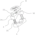
Fig. 6 is a schematic structural diagram of a fixing assembly in the fracturing manifold adjusting device according to the present invention.
Description of reference numerals: 1-bearing plate, 2-fracturing main pipe, 3-bearing table, 4-lifting block, 5-servo motor I, 6-threaded rod I, 7-bending guide frame, 8-sliding section, 9-servo motor II, 10-threaded rod II, 11-pipe joint, 12-connecting plate, 13-butt joint section, 14-inclined tee joint, 15-sleeve plate, 16-threaded sleeve block II, 17-threaded sleeve block I, 18-trapezoidal plate, 19-positioning resisting plate, 20-damping rotating shaft, 21-movable clasp, 22-guide plate, 23-arc-shaped resisting block, 24-adjusting stud, 25-sliding guide sleeve, 26-guide block, 27-fixing seat, 28-lifting slide block, 29-resisting spring, 30-connecting spring, 31-hand wheel, 32-adjusting rod, 33-horizontal plate, 34-vertical rod, 35-vertical spring, 36-rotating plate and 37-positioning arc groove.
Detailed Description
The technical scheme of the patent is further described in detail by combining the following specific embodiments:
it should be noted that the following detailed description is exemplary and is intended to provide further explanation of the disclosure. Unless defined otherwise, all technical and scientific terms used herein have the same meaning as commonly understood by one of ordinary skill in the art to which this application belongs.
It is noted that the terminology used herein is for the purpose of describing particular embodiments only and is not intended to be limiting of example embodiments according to the present application. As used herein, the singular forms "a", "an" and "the" are intended to include the plural forms as well, and it should be understood that when the terms "comprises" and/or "comprising" are used in this specification, they specify the presence of stated features, steps, operations, devices, components, and/or combinations thereof, unless the context clearly indicates otherwise.
In the present invention, terms such as "upper", "lower", "left", "right", "front", "rear", "vertical", "horizontal", "side", "bottom", and the like indicate orientations or positional relationships based on those shown in the drawings, and are only terms of relationships determined for convenience in describing structural relationships of the parts or elements of the present invention, and are not intended to refer to any parts or elements of the present invention, and are not to be construed as limiting the present invention.
In the present invention, terms such as "fixedly connected", "connected", and the like are to be understood in a broad sense, and mean either a fixed connection or an integrally connected or detachable connection; may be directly connected or indirectly connected through an intermediate. The specific meanings of the above terms in the present invention can be determined according to specific situations by persons skilled in the relevant scientific or technical field, and are not to be construed as limiting the present invention.
Example 1
Referring to fig. 1-6, a fracturing manifold adjusting device comprises a bearing plate 1, a bearing table 3 for supporting a fracturing main pipe 2 is arranged on the bearing plate 1, a fixing component for limiting the fracturing main pipe 2 is arranged on the bearing table 3, a bending guide frame 7 is slidably arranged on the bearing plate 1, the bending guide frame 7 comprises a sliding section 8 and a butt-joint section 13, a positioning resisting plate 19 arranged opposite to the side wall of an inclined tee 14 on the fracturing main pipe 2 is arranged on the butt-joint section 13,
a sliding guide sleeve 25 is slidably mounted on the bending guide frame 7, a trapezoidal plate 18 is mounted on the sliding guide sleeve 25 through an elastic abutting component, a positioning arc groove 37 is formed in the top of the trapezoidal plate 18, a mounting component for clamping the pipe joint 11 is mounted on the trapezoidal plate 18,
connecting plate 12 is installed to bending guide frame 7 one side, installs the subassembly that slides on connecting plate 12, installs deflector 22 on the subassembly that slides, and the sliding sleeve has cup jointed lagging 15 on deflector 22, installs coupling spring 30 between lagging 15 and the deflector 22, and sliding guide sleeve 25 rotates and installs on lagging 15.
A use method of the fracturing manifold adjusting device comprises the following steps:
s1: the fracturing main pipe 2 is placed on a bearing table 3, and the fracturing main pipe 2 and an inclined tee 14 connected with the fracturing main pipe are fixed through a fixing component;
s2: the movable bending guide frame 7 moves along the axial direction of the fracturing main pipe 2 until the positioning resisting plate 19 is abutted against the inclined tee joint 14;
s2: the adjusting sliding guide sleeve 25 moves along the bending guide frame 7, the sliding guide sleeve 25 slides along the sliding section 8 and the butt joint section 13 in sequence, and after the sliding guide sleeve 25 slides into the butt joint section 13, the trapezoidal plate 18 is rotated to be opposite to the inclined tee joint 14, so that the pipe joint 11 is adjusted to be opposite to the port of the inclined tee joint 14.
Example 2
Referring to fig. 1-6, on the basis of embodiment 1, in addition,
the side wall of the butt joint section 13 is rotatably provided with a damping rotating shaft 20, a rotating plate 36 is fixed on the damping rotating shaft 20, and the positioning resisting plate 19 is fixed with the rotating plate 36. Wherein, install servo motor I5 on loading board 1, servo motor I5's output shaft drive is connected with threaded rod I6, and threaded sleeve connects the screw thread cover piece I17 of fixing in the guide frame 7 bottom of buckling on the threaded rod I6.
As shown in fig. 1, the servo motor I5 is started to drive the threaded rod I6 to rotate, the threaded rod I6 drives the threaded sleeve block I17 to move rightwards, the bending guide frame 7 moves rightwards integrally, and after the positioning resisting plate 19 is abutted to the inclined tee 14, the servo motor I5 is closed, and the position adjustment of the bending guide frame 7 is realized.
The rotating plate 36 can rotate to a horizontal position through the damping rotating shaft 20 without being opposite to the inclined tee joint 14, so that the bending guide frame 7 can be moved and adjusted smoothly before other inclined tee joints 14 are butted with the pipe joint 11.
After the position of the bending guide frame 7 is adjusted, the sliding guide sleeve 25 is adjusted to slide through a sliding assembly, wherein the sliding assembly comprises a threaded sleeve block II16 fixed with the guide plate 22, a threaded rod II10 is connected to the threaded sleeve block II16 in a threaded manner, and the threaded rod II10 is driven to rotate by a servo motor II9 installed on the connecting plate 12.
The servo motor II9 drives the threaded rod II10 to rotate, the threaded rod II10 drives the threaded sleeve block II16 to linearly move, and at the moment, the threaded sleeve block II16 drives the guide plate 22 and the sleeve plate 15 to realize that the sliding guide sleeve 25 slides along the bending guide frame 7.
The elastic pushing component of the device comprises a guide block 26 vertically and slidably mounted in a sliding guide sleeve 25, the guide block 26 is in sliding fit with the bending guide frame 7, the top of the guide block 26 is fixed with the trapezoidal plate 18, and a pushing spring 29 is fixed between the bottom of the guide block 26 and the sliding guide sleeve 25. The elastic pushing component also comprises a lifting slide block 28 fixed on the side wall of the guide block 26, and the lifting slide block 28 is vertically connected with the sliding guide sleeve 25 in a sliding manner.
When the sliding guide sleeve 25 slides to the butt joint section 13, the trapezoidal plate 18 is rotated to be opposite to the port of the inclined tee joint 14, then the trapezoidal plate 18 is abutted to the inclined tee joint 14, the guide block 26 moves downwards relative to the sliding guide sleeve 25 under the elastic supporting effect of the abutting and pushing spring 29, finally, the inclined tee joint 14 is clamped with the positioning arc groove 37, the accurate positioning effect on the deflection angle of the trapezoidal plate 18 is achieved, at the moment, the pipe joint 11 is opposite to the inclined tee joint 14, and the connection of the inclined tee joint 14 and the pipe joint 11 is greatly facilitated.
In addition, the mounting assembly of the device comprises a movable clamp 21 corresponding to the fixed seat 27, the movable clamp 21 is mounted on the fixed seat 27 through bolt and nut connection, an adjusting stud 24 is mounted on the fixed seat 27, and an arc-shaped abutting block 23 abutted against the pipe joint 11 is in threaded connection with the adjusting stud 24.
The pipe joint 11 is arranged on the fixing seat 27, the movable clamp 21 is connected with the fixing seat 27 in a butt joint mode through bolts and nuts, the position limiting effect of the pipe joint 11 is achieved, in the butt joint process of the pipe joint 11 and the inclined tee joint 14, the arc-shaped pushing block 23 can be driven to move by rotating the adjusting stud 24, the arc-shaped pushing block 23 is enabled to push the pipe joint 11 to move and adjust towards the inclined tee joint 14, and the connection efficiency of the inclined tee joint 14 and the pipe joint 11 is improved.
The fixed subassembly of this device includes vertical pole 34 of vertical fixing on plummer 3, and slidable mounting has elevator 4 on vertical pole 34, is connected with vertical spring 35 between elevator 4 and the plummer 3, and horizontal plate 33 is installed on the 34 top of vertical pole, and threaded connection has the regulation pole 32 with 4 butts of elevator on the horizontal plate 33, adjusts the pole 32 top and is fixed with hand wheel 31.
The fracturing main pipe 2 is arranged between the bearing platform 3 and the lifting block 4, the adjusting rod 32 can be driven to rotate by screwing the hand wheel 31, the adjusting rod 32 vertically moves relative to the horizontal plate 33 and pushes the lifting block 4, the lifting block 4 moves downwards, the lifting block 4 and the bearing platform 3 are finally fixed with the fracturing main pipe 2, and the stability of the fracturing main pipe 2 in the connection process of the inclined tee joint 14 and the pipe joint 11 is guaranteed so as to improve the installation quality.
In conclusion, the sliding guide sleeve 25 can be guided to slide by the arranged bending guide frame 7, after the positioning resisting plate 19 is abutted to the side wall of the inclined tee 14, the positioning of the bending guide frame 7 after position adjustment is realized, and the sliding guide sleeve 25 slides along the butt joint section 13, so that the position limiting and adjusting effects of the pipe joint 11 and the inclined tee 14 are realized, and the butt joint operation of the inclined tee 14 and the pipe joint 11 of the fracturing main pipe 2 is greatly facilitated;
the trapezoidal plate 18 can be abutted against and pushed by the inclined tee joint 14, so that the inclined tee joint 14 can be clamped on the positioning arc groove 37 under the action of the elastic abutting and pushing assembly, the pipe joint 11 and the inclined tee joint 14 are accurately arranged relatively, and the mounting accuracy is greatly improved.
It should be noted that, although the present specification describes embodiments, each embodiment does not include only a single technical solution, and such description of the specification is only for clarity, and those skilled in the art should take the specification as a whole, and the technical solutions in the embodiments may be appropriately combined to form other embodiments understood by those skilled in the art, and the above embodiments only express the preferred embodiments of the technical solutions, and the description thereof is more specific and detailed, but not construed as limiting the scope of the claims of the technical solutions. It should be noted that, for those skilled in the art, various changes, modifications and substitutions can be made without departing from the spirit of the present invention, and these changes and substitutions belong to the protection scope of the present invention. The protection scope of this technical solution patent should be subject to the appended claims.