CN114767247A - Detachable screw for fixing anterior pelvic ring and internal fixing device - Google Patents
Detachable screw for fixing anterior pelvic ring and internal fixing device Download PDFInfo
- Publication number
- CN114767247A CN114767247A CN202210451398.5A CN202210451398A CN114767247A CN 114767247 A CN114767247 A CN 114767247A CN 202210451398 A CN202210451398 A CN 202210451398A CN 114767247 A CN114767247 A CN 114767247A
- Authority
- CN
- China
- Prior art keywords
- nail
- tail
- screw
- hole
- barrel
- Prior art date
- Legal status (The legal status is an assumption and is not a legal conclusion. Google has not performed a legal analysis and makes no representation as to the accuracy of the status listed.)
- Granted
Links
Images


Classifications
-
- A—HUMAN NECESSITIES
- A61—MEDICAL OR VETERINARY SCIENCE; HYGIENE
- A61B—DIAGNOSIS; SURGERY; IDENTIFICATION
- A61B17/00—Surgical instruments, devices or methods
- A61B17/56—Surgical instruments or methods for treatment of bones or joints; Devices specially adapted therefor
- A61B17/58—Surgical instruments or methods for treatment of bones or joints; Devices specially adapted therefor for osteosynthesis, e.g. bone plates, screws or setting implements
- A61B17/68—Internal fixation devices, including fasteners and spinal fixators, even if a part thereof projects from the skin
- A61B17/84—Fasteners therefor or fasteners being internal fixation devices
- A61B17/86—Pins or screws or threaded wires; nuts therefor
- A61B17/8605—Heads, i.e. proximal ends projecting from bone
-
- A—HUMAN NECESSITIES
- A61—MEDICAL OR VETERINARY SCIENCE; HYGIENE
- A61B—DIAGNOSIS; SURGERY; IDENTIFICATION
- A61B17/00—Surgical instruments, devices or methods
- A61B17/56—Surgical instruments or methods for treatment of bones or joints; Devices specially adapted therefor
- A61B17/58—Surgical instruments or methods for treatment of bones or joints; Devices specially adapted therefor for osteosynthesis, e.g. bone plates, screws or setting implements
- A61B17/68—Internal fixation devices, including fasteners and spinal fixators, even if a part thereof projects from the skin
- A61B17/84—Fasteners therefor or fasteners being internal fixation devices
- A61B17/86—Pins or screws or threaded wires; nuts therefor
- A61B17/8625—Shanks, i.e. parts contacting bone tissue
-
- A—HUMAN NECESSITIES
- A61—MEDICAL OR VETERINARY SCIENCE; HYGIENE
- A61B—DIAGNOSIS; SURGERY; IDENTIFICATION
- A61B17/00—Surgical instruments, devices or methods
- A61B17/56—Surgical instruments or methods for treatment of bones or joints; Devices specially adapted therefor
- A61B17/58—Surgical instruments or methods for treatment of bones or joints; Devices specially adapted therefor for osteosynthesis, e.g. bone plates, screws or setting implements
- A61B17/68—Internal fixation devices, including fasteners and spinal fixators, even if a part thereof projects from the skin
- A61B17/84—Fasteners therefor or fasteners being internal fixation devices
- A61B17/86—Pins or screws or threaded wires; nuts therefor
- A61B17/8665—Nuts
-
- A—HUMAN NECESSITIES
- A61—MEDICAL OR VETERINARY SCIENCE; HYGIENE
- A61B—DIAGNOSIS; SURGERY; IDENTIFICATION
- A61B17/00—Surgical instruments, devices or methods
- A61B17/56—Surgical instruments or methods for treatment of bones or joints; Devices specially adapted therefor
- A61B17/58—Surgical instruments or methods for treatment of bones or joints; Devices specially adapted therefor for osteosynthesis, e.g. bone plates, screws or setting implements
- A61B17/68—Internal fixation devices, including fasteners and spinal fixators, even if a part thereof projects from the skin
- A61B17/84—Fasteners therefor or fasteners being internal fixation devices
- A61B17/86—Pins or screws or threaded wires; nuts therefor
- A61B17/8685—Pins or screws or threaded wires; nuts therefor comprising multiple separate parts
-
- A—HUMAN NECESSITIES
- A61—MEDICAL OR VETERINARY SCIENCE; HYGIENE
- A61B—DIAGNOSIS; SURGERY; IDENTIFICATION
- A61B17/00—Surgical instruments, devices or methods
- A61B17/56—Surgical instruments or methods for treatment of bones or joints; Devices specially adapted therefor
- A61B17/58—Surgical instruments or methods for treatment of bones or joints; Devices specially adapted therefor for osteosynthesis, e.g. bone plates, screws or setting implements
- A61B17/68—Internal fixation devices, including fasteners and spinal fixators, even if a part thereof projects from the skin
- A61B17/84—Fasteners therefor or fasteners being internal fixation devices
- A61B17/86—Pins or screws or threaded wires; nuts therefor
- A61B2017/8655—Pins or screws or threaded wires; nuts therefor with special features for locking in the bone
Landscapes
- Health & Medical Sciences (AREA)
- Orthopedic Medicine & Surgery (AREA)
- Surgery (AREA)
- Life Sciences & Earth Sciences (AREA)
- Heart & Thoracic Surgery (AREA)
- Nuclear Medicine, Radiotherapy & Molecular Imaging (AREA)
- Engineering & Computer Science (AREA)
- Biomedical Technology (AREA)
- Neurology (AREA)
- Medical Informatics (AREA)
- Molecular Biology (AREA)
- Animal Behavior & Ethology (AREA)
- General Health & Medical Sciences (AREA)
- Public Health (AREA)
- Veterinary Medicine (AREA)
- Orthopedics, Nursing, And Contraception (AREA)
Abstract
本发明提供了一种用于骨盆前环固定的可拆卸螺钉及内固定装置,螺钉包括主钉、钉筒、固定件和内螺钉;钉筒内通孔呈阶梯状,包括连通的第一通孔和直径大于第一通孔的第二通孔,第一、第二通孔分别远离和靠近主钉,主钉包括钉尾和钉杆且一体成型,钉尾能穿过第二通孔;钉筒第一通孔的内壁设置有内螺纹,内螺钉通过内螺纹与钉筒连接;固定件设置在钉筒内、且位于钉尾和内螺钉之间,通过固定件将钉尾滞留在钉筒内,固定件包括支撑部和固定在支撑部靠近钉尾一端且沿支撑部周向排列的多个弧形弹簧片,弧形的弧心朝向钉尾,多个弹簧片抱紧或松开钉尾。内固定装置,包括连接横杆和至少两个上述螺钉,螺钉之间通过连接横杆连接,进而减小术后的不适感。
The invention provides a detachable screw and an internal fixation device for fixing an anterior pelvic ring. The screw comprises a main nail, a nail barrel, a fixing piece and an inner screw; The hole and the second through hole with a diameter larger than the first through hole, the first and second through holes are respectively away from and close to the main nail, the main nail includes a nail tail and a nail rod and is integrally formed, and the nail tail can pass through the second through hole; The inner wall of the first through hole of the nail barrel is provided with an inner thread, and the inner screw is connected with the nail barrel through the inner thread; the fixing member is arranged in the nail barrel and between the nail tail and the inner screw, and the nail tail is retained in the nail by the fixing member In the barrel, the fixing member includes a support portion and a plurality of arc-shaped spring pieces fixed on one end of the support portion close to the nail tail and arranged along the circumferential direction of the support portion. Nail tail. The internal fixation device includes a connecting crossbar and at least two of the above-mentioned screws, and the screws are connected by the connecting crossbar, thereby reducing postoperative discomfort.
Description
技术领域technical field
本发明涉及骨科医疗器械技术领域,具体涉及一种用于骨盆前环固定的可拆卸螺钉及内固定装置。The invention relates to the technical field of orthopedic medical devices, in particular to a detachable screw and an internal fixation device for fixing an anterior pelvic ring.
背景技术Background technique
对于老年脆性骨盆前环损伤,目前临床上一般采用微创经皮骨盆前环内固定术(Minimally Invasive Anterior Pelvic Ring Internal Fixator)。此术式中应用最广泛、最有效的器械称为内固定架(INFIX)。内固定架的设计初衷即为稳定骨盆前环,因此骨盆前环损伤,包括耻骨联合分离、耻骨支骨折是其最佳适应症。由于内固定架位于下腹部骨盆前方,体形消瘦的患者会出现主观不适感,尤其对于端坐体位,术后通常出现主观不适感并影响日常生活,但在取出内固定架后该不适感即消失。因此,在骨折愈合后,应二次手术取出内固定架。Minimally Invasive Anterior Pelvic Ring Internal Fixator (Minimally Invasive Anterior Pelvic Ring Internal Fixator) is generally used clinically for elderly fragile anterior pelvic ring injuries. The most widely used and effective device in this procedure is called the internal fixator (INFIX). The original design of the internal fixator is to stabilize the anterior pelvic ring, so anterior pelvic ring injuries, including pubic symphysis separation and pubic ramus fractures are the best indications. Because the internal fixator is located in front of the lower abdomen and pelvis, patients with thin body will experience subjective discomfort, especially in the sitting position, subjective discomfort usually occurs after surgery and affects daily life, but the discomfort disappears after the internal fixator is removed . Therefore, after the fracture has healed, the internal fixator should be removed by a second operation.
目前,内固定架的主钉和连接横杆的钉帽是一体化设计,但是有些特殊骨折需要把主钉长时间留置,而横杆引起不适,需要早期取出。然而,在骨盆前环损伤康复手术后的早期,骨盆恢复程度不够,螺钉除主钉外其余部分不易取出。At present, the main nail of the internal fixator and the nail cap connecting the crossbar are integrated design, but for some special fractures, the main nail needs to be indwelled for a long time, and the crossbar causes discomfort and needs to be removed early. However, in the early stage after rehabilitation surgery for anterior pelvic ring injury, the degree of pelvic recovery is not sufficient, and the rest of the screws except the main screw are not easily removed.
针对现有技术中对于安装了内固定架的患者,难以取出主钉外其余部分的问题,还未提出有效的解决方案。In view of the problem in the prior art that it is difficult to remove the rest of the main nail for a patient with an internal fixator installed, no effective solution has been proposed yet.
发明内容SUMMARY OF THE INVENTION
有鉴于此,本发明提供了一种用于骨盆前环固定的可拆卸螺钉及内固定装置,解决了现有技术中对于安装了内固定架的患者,难以取出主钉外其余部分的问题。In view of this, the present invention provides a detachable screw and an internal fixation device for fixing an anterior pelvic ring, which solves the problem in the prior art that it is difficult to remove the rest of the main nail for patients with an internal fixator installed.
为此,本发明提供了如下技术方案:For this reason, the present invention provides the following technical solutions:
本发明第一方面,提供了用于骨盆前环固定的可拆卸螺钉,包括:主钉、钉筒、固定件和内螺钉;A first aspect of the present invention provides a detachable screw for fixing an anterior pelvic ring, including: a main nail, a screw barrel, a fixing member and an inner screw;
所述钉筒内的通孔呈阶梯状,包括连通的第一通孔和第二通孔,所述第一通孔远离所述主钉,所述第二通孔靠近所述主钉,所述第一通孔的直径大于所述第二通孔的直径,所述主钉包括钉尾和钉杆,所述钉尾和钉杆一体成型,所述钉尾能够穿过所述第二通孔;The through holes in the nail barrel are stepped, including a first through hole and a second through hole that communicate with each other. The first through hole is far away from the main nail, and the second through hole is close to the main nail, so The diameter of the first through hole is larger than the diameter of the second through hole, the main nail includes a nail tail and a nail shaft, the nail tail and the nail shaft are integrally formed, and the nail tail can pass through the second through hole. hole;
所述钉筒第一通孔处的内壁设置有内螺纹,所述内螺钉通过所述内螺纹与所述钉筒连接;The inner wall at the first through hole of the nail barrel is provided with an inner thread, and the inner screw is connected with the nail barrel through the inner thread;
所述固定件设置在所述钉筒内、且位于钉尾和所述内螺钉之间,通过固定件将所述钉尾滞留在所述钉筒内,所述固定件包括支撑部和固定在所述支撑部靠近钉尾一端的多个弹簧片,所述多个弹簧片沿所述支撑部周向排列,所述弹簧片呈弧形,弧形的弧心朝向钉尾,所述多个弹簧片包括所述内螺钉旋入所述钉筒时抱紧钉尾的第一状态和所述内螺钉旋出所述钉筒时松开钉尾的第二状态。The fixing member is arranged in the nail barrel and is located between the nail tail and the inner screw, the nail tail is retained in the nail barrel by the fixing member, and the fixing member includes a support part and a fixing part. The support portion is close to a plurality of spring pieces at one end of the nail tail, the plurality of spring pieces are arranged along the circumferential direction of the support portion, the spring pieces are arc-shaped, and the arc center of the arc faces the nail tail. The spring piece includes a first state of tightening the nail tail when the inner screw is screwed into the nail barrel and a second state of loosening the nail tail when the inner screw is screwed out of the nail barrel.
可选地,所述钉杆上的螺纹包括粗牙螺纹和细牙螺纹,所述粗牙螺纹靠近所述钉尾,所述细牙螺纹远离所述钉尾。Optionally, the threads on the shank include coarse threads and fine threads, the coarse threads are close to the nail tail, and the fine threads are far away from the nail tail.
可选地,所述主钉内部设置有空腔,所述空腔贯穿所述主钉。Optionally, a cavity is provided inside the main nail, and the cavity penetrates the main nail.
可选地,所述钉杆远离所述钉尾的一端的侧壁设置有多个注射孔,所述注射孔与所述空腔连通。Optionally, a side wall of one end of the nail rod away from the nail tail is provided with a plurality of injection holes, and the injection holes communicate with the cavity.
可选地,所述钉杆沿周向设置多个收纳槽,所述收纳槽内设置有凸起的切削刃,所述切削刃用于在旋转主钉时,切割骨骼。Optionally, the nail shaft is provided with a plurality of receiving grooves along the circumferential direction, and a raised cutting edge is disposed in the receiving groove, and the cutting edge is used to cut the bone when the main nail is rotated.
本发明第二方面,提供了一种内固定装置,包括连接横杆和至少两个根据上述第一方面中任一项所述的用于骨盆前环固定的可拆卸螺钉,所述用于骨盆前环固定的可拆卸螺钉之间通过所述连接横杆连接;In a second aspect of the present invention, an internal fixation device is provided, comprising a connecting crossbar and at least two detachable screws for pelvic anterior ring fixation according to any one of the above-mentioned first aspects. The detachable screws fixed by the front ring are connected by the connecting cross bar;
所述钉筒远离所述主钉的侧壁上设置有两个相对的卡槽,所述连接横杆卡接入所述卡槽内,所述连接横杆固定在所述固定件和所述内螺钉之间。The side wall of the nail barrel away from the main nail is provided with two opposite clamping grooves, the connecting crossbar is inserted into the clamping groove, and the connecting crossbar is fixed on the fixing member and the between the inner screws.
可选地,所述固定件远离所述主钉的端面上设置有限位槽,所述连接横杆与所述限位槽匹配。Optionally, a limiting groove is provided on the end surface of the fixing member away from the main nail, and the connecting crossbar is matched with the limiting groove.
可选地,所述连接横杆包括弹性部和刚性部,所述弹性部和所述刚性部交替连接。Optionally, the connecting crossbar includes an elastic part and a rigid part, and the elastic part and the rigid part are alternately connected.
可选地,所述弹性部为弹簧,所述弹簧的两个端部分别与所述刚性部固定连接。Optionally, the elastic portion is a spring, and two ends of the spring are respectively fixedly connected to the rigid portion.
本发明技术方案,具有如下优点:The technical scheme of the present invention has the following advantages:
本发明提供了一种用于骨盆前环固定的可拆卸螺钉及内固定装置,通过本发明解决了现有技术中对于安装了内固定架的患者,难以取出主钉外其余部分的问题。在本发明中,通过内螺钉挤压固定件,使得固定件上的弹簧片压缩变形,进而抱紧主钉钉尾,使得整个螺钉牢固地固定在骨盆前环处;而通过将用于骨盆前环固定的可拆卸螺钉上的内螺钉取出,固定件上的弹簧片恢复自然状态,主钉的钉尾可以从多个弹簧片中脱离,进而可以实现用于骨盆前环固定的可拆卸螺钉的拆卸。因此,在主钉不需要取出时,可以将用于骨盆前环固定的可拆卸螺钉除主钉外的其余部分取出,减小患者术后的不适感。The present invention provides a detachable screw and an internal fixation device for fixing an anterior pelvic ring. The present invention solves the problem in the prior art that it is difficult to remove the rest of the main screw for a patient with an internal fixator installed. In the present invention, the inner screw is used to squeeze the fixing piece, so that the spring plate on the fixing piece is compressed and deformed, and then the tail of the main screw is held tightly, so that the whole screw is firmly fixed at the anterior ring of the pelvis; The inner screw on the detachable screw for ring fixation is taken out, the spring piece on the fixing piece returns to its natural state, and the nail tail of the main nail can be detached from the plurality of spring pieces, so that the detachable screw for pelvic anterior ring fixation can be realized. disassemble. Therefore, when the main nail does not need to be removed, the remaining part of the detachable screw used for the fixation of the anterior pelvic ring except the main nail can be removed to reduce postoperative discomfort of the patient.
附图说明Description of drawings
为了更清楚地说明本发明具体实施方式或现有技术中的技术方案,下面将对具体实施方式或现有技术描述中所需要使用的附图作简单地介绍,显而易见地,下面描述中的附图是本发明的一些实施方式,对于本领域普通技术人员来讲,在不付出创造性劳动的前提下,还可以根据这些附图获得其他的附图。In order to illustrate the specific embodiments of the present invention or the technical solutions in the prior art more clearly, the following briefly introduces the accompanying drawings that need to be used in the description of the specific embodiments or the prior art. Obviously, the accompanying drawings in the following description The drawings are some embodiments of the present invention. For those of ordinary skill in the art, other drawings can also be obtained based on these drawings without creative efforts.
图1是根据本发明的用于骨盆前环固定的可拆卸螺钉的结构示意图;1 is a schematic structural diagram of a detachable screw for fixation of an anterior pelvic ring according to the present invention;
图2是根据本发明的主钉的结构示意图;Fig. 2 is the structural schematic diagram of the main nail according to the present invention;
图3是根据本发明的钉筒的结构示意图;Fig. 3 is the structural representation of the nail barrel according to the present invention;
图4是根据本发明的固定件的结构示意图;Fig. 4 is the structural schematic diagram of the fixing member according to the present invention;
图5是根据本发明的固定件处于第一状态时沿主钉长度方向的剖面图;5 is a cross-sectional view along the length of the main nail when the fastener according to the present invention is in the first state;
图6是根据本发明的固定件处于第二状态时沿主钉长度方向的剖面图;6 is a cross-sectional view along the length of the main nail when the fastener according to the present invention is in a second state;
图7是根据本发明的设置切削刃的主钉的结构示意图;Fig. 7 is the structural schematic diagram of the main nail provided with cutting edge according to the present invention;
图8是根据本发明的内固定装置的结构示意图;FIG. 8 is a schematic structural diagram of an internal fixation device according to the present invention;
图9是根据本发明的连接横杆的结构示意图。FIG. 9 is a schematic structural diagram of a connecting cross bar according to the present invention.
图中,In the figure,
1、主钉;11、钉尾;111、空腔;12、钉杆;121、粗牙螺纹;122、细牙螺纹;123、注射孔;124、收纳槽;125、切削刃;2、钉筒;21、内螺纹;22、卡槽;3、固定件;31、支撑部;32、弹簧片;33、限位槽;4、内螺钉;5、连接横杆;51、弹性部;52、刚性部。1. Main nail; 11. Nail tail; 111. Cavity; 12. Nail stem; 121, coarse thread; 122, fine thread; 123, injection hole; 124, receiving groove; 125, cutting edge; 2, nail barrel; 21, internal thread; 22, card slot; 3, fixing part; 31, support part; 32, spring sheet; 33, limit slot; 4, inner screw; 5, connecting cross bar; 51, elastic part; 52 , Rigid part.
具体实施方式Detailed ways
下面将结合本发明中的附图,对本发明中的技术方案进行清楚、完整地描述,显然,所描述的实施例仅仅是本发明一部分实施例,而不是全部的实施例。基于本发明中的实施例,本领域技术人员在没有做出创造性劳动前提下所获得的所有其他实施例,都属于本发明保护的范围。The technical solutions in the present invention will be clearly and completely described below with reference to the accompanying drawings of the present invention. Obviously, the described embodiments are only a part of the embodiments of the present invention, but not all of the embodiments. Based on the embodiments of the present invention, all other embodiments obtained by those skilled in the art without creative efforts shall fall within the protection scope of the present invention.
在本发明的描述中,需要理解的是,术语“中心”、“纵向”、“横向”、“长度”、“宽度”、“厚度”、“上”、“下”、“前”、“后”、“左”、“右”、“竖直”、“水平”、“顶”、“底”、“内”、“外”等指示的方位或位置关系为基于附图所示的方位或位置关系,仅是为了便于描述本发明和简化描述,而不是指示或暗示所指的装置或元件必须具有特定的方位、以特定的方位构造和操作,因此不能理解为对本发明的限制。此外,术语“第一”、“第二”仅用于描述目的,而不能理解为指示或暗示相对重要性或者隐含指明所指示的技术特征的数量。由此,限定有“第一”、“第二”的特征可以明示或者隐含地包括一个或者更多个特征。在本发明的描述中,“多个”的含义是两个或两个以上,除非另有明确具体的限定。In the description of the present invention, it should be understood that the terms "center", "longitudinal", "lateral", "length", "width", "thickness", "upper", "lower", "front", " The orientation or positional relationship indicated by "rear", "left", "right", "vertical", "horizontal", "top", "bottom", "inside", "outside", etc. is based on the orientation shown in the drawings Or the positional relationship is only for the convenience of describing the present invention and simplifying the description, rather than indicating or implying that the referred device or element must have a specific orientation, be constructed and operated in a specific orientation, and therefore should not be construed as a limitation of the present invention. In addition, the terms "first" and "second" are only used for descriptive purposes, and should not be construed as indicating or implying relative importance or implying the number of indicated technical features. Thus, features defined as "first", "second" may expressly or implicitly include one or more features. In the description of the present invention, "plurality" means two or more, unless otherwise expressly and specifically defined.
在本发明中,“示例性”一词用来表示“用作例子、例证或说明”。本发明中被描述为“示例性”的任何实施例不一定被解释为比其它实施例更优选或更具优势。为了使本领域任何技术人员能够实现和使用本发明,给出了以下描述。在以下描述中,为了解释的目的而列出了细节。应当明白的是,本领域普通技术人员可以认识到,在不使用这些特定细节的情况下也可以实现本发明。在其它实例中,不会对公知的结构和过程进行详细阐述,以避免不必要的细节使本发明的描述变得晦涩。因此,本发明并非旨在限于所示的实施例,而是与符合本发明所公开的原理和特征的最广范围相一致。In the present invention, the word "exemplary" is used to mean "serving as an example, illustration or illustration". Any embodiment of this disclosure described as "exemplary" is not necessarily to be construed as preferred or advantageous over other embodiments. The following description is presented to enable any person skilled in the art to make and use the present invention. In the following description, details are set forth for the purpose of explanation. It will be understood by one of ordinary skill in the art that the present invention may be practiced without the use of these specific details. In other instances, well-known structures and procedures have not been described in detail so as not to obscure the description of the present invention with unnecessary detail. Thus, the present invention is not intended to be limited to the embodiments shown but is to be accorded the widest scope consistent with the principles and features disclosed herein.
此外,下面所描述的本发明不同实施方式中所涉及的技术特征只要彼此之间未构成冲突就可以相互结合。In addition, the technical features involved in the different embodiments of the present invention described below can be combined with each other as long as they do not conflict with each other.
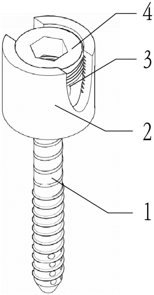
在本发明中提供了一种用于骨盆前环固定的可拆卸螺钉及内固定装置,可用于骨盆前环损伤的术后固定,例如,耻骨联合分离术后固定和耻骨支骨折术后固定。图1是根据本发明的用于骨盆前环固定的可拆卸螺钉的结构示意图,如图1所示,该用于骨盆前环固定的可拆卸螺钉包括:主钉1、钉筒2、固定件3和内螺钉4。具体地,通过将主钉1、钉筒2、固定件3以及内螺钉4进行连接,形成用于骨盆前环固定的可拆卸螺钉,将该用于骨盆前环固定的可拆卸螺钉置于骨盆骨折处,可以有效地对骨折处进行固定。The present invention provides a detachable screw and an internal fixation device for anterior pelvic ring fixation, which can be used for postoperative fixation of anterior pelvic ring injuries, such as post-operative fixation of symphysis pubis separation and post-operative fixation of pubic ramus fractures. Fig. 1 is a schematic structural diagram of a detachable screw for fixing anterior pelvic ring according to the present invention. As shown in Fig. 1 , the detachable screw for fixing anterior pelvic ring includes: a
如图2和图3所示,钉筒2内的通孔呈阶梯状,包括连通的第一通孔和第二通孔,第一通孔远离主钉1,第二通孔靠近主钉1,第一通孔的直径大于第二通孔的直径,主钉1包括钉尾11和钉杆12,钉尾11和钉杆12一体成型,钉尾11能够穿过第二通孔。具体地,在拆卸该用于骨盆前环固定的可拆卸螺钉时,由于钉尾11可以穿过第二通孔,因此主钉1在没有限制的情况下可以从钉筒2中脱离,换言之,当主钉1固定在骨骼中时,钉筒2沿着主钉1长度的方向远离骨骼,钉尾11穿过第一通孔和第二通孔,钉筒2与钉尾11分离。As shown in FIG. 2 and FIG. 3 , the through holes in the
钉筒2第一通孔处的内壁设置有内螺纹21,内螺钉4通过内螺纹21与钉筒2连接;固定件3设置在钉筒2内、且位于钉尾11和内螺钉4之间,通过固定件3将钉尾11滞留在钉筒2内,固定件3包括支撑部31和固定在支撑部31靠近钉尾11一端的多个弹簧片32,多个弹簧片32沿支撑部31周向排列,弹簧片32呈弧形,弧形的弧心朝向钉尾11,如图4所示,多个弹簧片32包括内螺钉4旋入钉筒2时抱紧钉尾11的第一状态(如图5所示)和内螺钉4旋出钉筒2时的松开钉尾11的第二状态(如图6所示)。具体地,将固定件3安装到钉筒2中,然后通过内螺钉4将固定件3限制在钉筒2中,此时内螺钉4并未挤压固定件3,固定件3上的多个弹簧片32不会挤压钉筒2而发生形变,固定件3处于第二状态;由于固定件3处于第二状态,因此主钉1的钉尾11可以穿过第二通孔伸入多片弹簧片32之间,同时,由于每一个弹簧片32自然状态下的长度大于钉尾11的长度,使得多个弹簧片32可以包住钉尾11,并且此时多个弹簧片32并未抱紧钉尾11,使得钉尾11可以从多个弹簧片32之间脱出,进而脱离钉筒2,然后通过内螺钉4挤压固定件3,使得固定件3向主钉1所在的方向移动,当多个弹簧片32与钉筒2底壁接触时,钉筒2的底壁阻碍固定件3移动,但是随着内螺钉4继续挤压固定件3,多个弹簧片32受到钉筒2底壁的作用,多个弹簧片32的弯曲加剧,使得多个弹簧片32的腹部向钉筒2侧壁方向靠近,弹簧片32远离支撑部31的一端沿长度方向弯曲形变,进而多个弹簧片32远离支撑部31的一端向支撑部31靠近,多个弹簧片32抱紧钉尾11,固定件3处于第一状态,此时钉尾11难以从多个弹簧片32之间脱离,形成用于骨盆前环固定的可拆卸螺钉;而且,多个弹簧片32也填满了钉筒2与钉尾11之间的空隙,避免钉尾11在钉筒2内晃动,固定比较牢固。该用于骨盆前环固定的可拆卸螺钉置入患者骨折处后,在需要将除主钉1外其余部分取出时,取出内螺钉4,固定件3向远离主钉1的方向移动,使得钉筒2底壁对多个弹簧片32的作用减小,多个弹簧片32逐步恢复到自然状态,最终,固定件3恢复到第二状态,钉尾11可以从多个弹簧片32中脱出,进而实现将主钉1保留在患者骨折处,实现用于骨盆前环固定的可拆卸螺钉的拆卸取出。The inner wall of the first through hole of the
当固定件3处于第一状态或者自然状态时,多个弹簧片32靠近主钉1的一端所围成的区域的直径略小于钉尾11的最大直径,但是大于钉杆12的直径。由于弹簧片32具有弹力,因此将钉尾11从多个弹簧片32靠近主钉1的一端所围成的区域伸入多个弹簧片32围成的空间时,多个弹簧片32可以向远离弧心的一侧张开,使得钉尾11伸入多个弹簧片32围成的空间,而由于钉杆12的直径小于多个弹簧片32靠近主钉1的一端所围成的区域的直径,多个弹簧片32不再发生形变,恢复到初始位置,而此时钉尾11处于多个弹簧片32围成的空间中,在不受力的情况下不易脱离固定件3。When the fixing
现有技术中用于骨盆骨折的螺钉没有可拆卸功能,通常采用主钉和钉筒一体成型的方式,进而在拆卸用于骨盆骨折的螺钉时,不能将钉筒取出。在本实施例中,区别于现有技术设计了一种用于骨盆前环固定的可拆卸螺钉,由于主钉1的钉尾11可以穿过第二通孔,进而可以在保留主钉1的前提下取出钉筒2和固定件3等。本实施例解决了现有技术中对于安装了内固定架的患者,难以取出主钉1外其余的部分的问题,减小了患者术后的不适感。The screws used for pelvic fractures in the prior art have no detachable function, and the main nail and the screw barrel are usually integrally formed, so that when the screws for pelvic fractures are removed, the screw barrel cannot be taken out. In this embodiment, different from the prior art, a detachable screw for fixing the anterior pelvic ring is designed. Since the
为了说明钉杆12上的螺纹,在一些可选实施例中,钉杆12上的螺纹包括粗牙螺纹121和细牙螺纹122,粗牙螺纹121靠近钉尾11,细牙螺纹122远离钉尾11。具体地,粗牙螺纹121强度高,固定性能好;细牙螺纹122密封性好,在不采取防松措施的前提下,细牙螺纹122的防松性能优于粗牙螺纹121,但是细牙螺纹122的强度低。因此,将钉杆12上的螺纹设置为粗牙螺纹121和细牙螺纹122,可以有效地增强主钉1的把持力。本领域技术人员应当知晓,钉杆12上的螺纹设置为粗牙螺纹121和细牙螺纹122不用于限定本发明,其它类型的螺纹也在本发明保护范围之内,例如,粗牙螺纹121之间设置细牙螺纹122。To illustrate the threads on the
为了说明主钉1,在一些可选实施例中,主钉1内部设置有空腔111,空腔111贯穿主钉1。将主钉1内部设置有空腔111,可以释放骨折处的压力,使得骨折处可以更好的恢复。另外,克氏针可以穿过主钉1上的空腔111,进而通过克氏针对主钉1进行引导,使得主钉1可以准确置入骨盆骨折处,有效促进主钉1对骨盆骨折的固定。具体地,在通过克氏针进行引导时,先在骨折处置入一根克氏针,然后将主钉1穿过克氏针,进而将该用于骨盆前环固定的可拆卸螺钉置入克氏针所在的位置,最后退出克氏针。To illustrate the
为了进一步说明主钉1,在一些可选实施例中,钉杆12远离钉尾11的一端的侧壁设置有多个注射孔123,注射孔123与空腔111连通。在将主钉1置入骨盆骨折处后,可以从主钉1尾部向空腔111中注入骨水泥,骨水泥可以通过注射孔123进入骨盆骨折处,有利于骨盆骨折处的恢复。同时,由于老年人通常患有骨质疏松,因此在发生骨折时,骨骼损伤程度比较严重。通过在主钉1中置入骨水泥,可以提升主钉1的机械强度,有利于骨折的术后康复。In order to further illustrate the
在另一些可选实施例中,如图6所示,钉杆12沿周向设置多个收纳槽124,收纳槽124内设置有凸起的切削刃125,切削刃125用于在旋转主钉1时,切割骨骼。在主钉1置入患者骨盆骨折处一段时间后,患者骨盆骨折处恢复后需要将主钉1取出,而由于主钉1周围的骨骼也逐步恢复,阻碍主钉1的取出,使得主钉1容易产生损伤,而通过切削刃125的作用,可以在旋转主钉1时切割主钉1周围的骨骼,并且切割下的骨骼碎屑进入收纳槽124,进而有利于主钉1的取出,并且在取出主钉1时带出骨骼碎屑,防止主钉1产生损伤。In other optional embodiments, as shown in FIG. 6 , the
本实施例还提供一种内固定装置,如图7所示,包括连接横杆5和至少两个根据上述实施例中任一项的用于骨盆前环固定的可拆卸螺钉,用于骨盆前环固定的可拆卸螺钉之间通过连接横杆5连接。利用连接横杆5将多个用于骨盆前环固定的可拆卸螺钉连接在一起形成内固定装置,可以对骨折的骨骼起到较好的固定作用。This embodiment also provides an internal fixation device, as shown in FIG. 7 , comprising a connecting
钉筒2远离主钉1的侧壁上设置有两个相对的卡槽22,连接横杆5卡接入卡槽22内,连接横杆5固定在固定件3和内螺钉4之间。通过在钉筒2上设置有两个相对的卡槽22,并且卡槽22与连接横杆5匹配,使得连接横杆5可以卡接入卡槽22中。具体地,将固定件3安装到钉筒2中,将连接横杆5卡接入卡槽22中,然后将主钉1的钉尾11置入多个弹簧片32之间,最后旋入内螺钉4挤压连接横杆5和固定件3,使得固定件3处于第一状态,抱紧钉尾11,形成内固定装置。在将内固定装置置入患者骨折处后,可以在保留主钉1的前提下取出钉筒2、固定件3、内螺钉4和连接横杆5,进而在不影响患者恢复的前提下,可以降低患者的不适感。The side wall of the
为了说明固定件3,在一些可选实施例中,固定件3远离主钉1的端面上设置有限位槽33,连接横杆5与限位槽33匹配。由于在固定件3上设置有与连接横杆5匹配的限位槽33,可以对连接横杆5起到很好的固定作用。To illustrate the fixing
为了说明连接横杆5,在一些可选实施例中,如图8所示,连接横杆5包括弹性部51和刚性部52,弹性部51和刚性部52交替连接。具体地,通过连接横杆5连接多个用于骨盆前环固定的可拆卸螺钉时,连接横杆5的刚性部52卡接在卡槽22中,防止连接横杆5脱离钉筒2。同时,通过两个刚性部52之间的弹性部51的作用可以弯曲连接横杆5,进而在置入内固定装置时,可以通过弹性部51的作用将连接横杆5弯曲,使得主钉1的钉杆12可以钉入适当的位置,对骨盆骨折可以起到更好的固定作用。In order to illustrate the connecting
为了进一步说明连接横杆5,在一些可选实施例中,弹性部51为弹簧,弹簧的两个端部分别与刚性部52固定连接。通过弹簧的作用可以使得连接横杆5产生弯曲,便于内固定装置对骨折处进行固定。本领域技术人员应当知晓,弹性部51为弹簧不用于限定本发明,通过其他结构或者材料构成的弹性部51也在本发明保护范围之内,例如硅胶棒和通过金属网形成的棒状结构。In order to further illustrate the connecting
在一些可能的实施例中,通过内固定装置来对患者骨折处进行固定,具体过程如下:In some possible embodiments, the patient's fracture is fixed by an internal fixation device, and the specific process is as follows:
(1)由于在主钉1的钉尾11上设置有六边形的通孔,通过与六边形通孔匹配的六边形扳手将多个主钉1分别钉入患者骨折处;(1) Since the
(2)将钉筒2套在主钉1的钉尾11上,钉尾11穿过第二通孔进入钉筒2中;(2) Put the
(3)将固定件3穿过第一通孔安装到钉筒2内,略微用力挤压固定件3,固定件3上的多个弹簧片32挤压钉尾11,使得多个弹簧片32远离支撑部31的一端向钉筒2内壁靠近,随着固定件3向主钉方向移动,多个弹簧片32包围钉尾11;(3) Install the fixing
(4)将连接横杆5放置于固定件3的限位槽33中,并且连接横杆5卡接到钉筒2侧壁上的两个相对的卡槽22中;(4) The connecting
(5)将内螺钉4通过钉筒2第一通孔处的内壁设置的内螺纹21旋入钉筒,随着内螺钉4的旋入,内螺钉4挤压连接横杆5,进而挤压固定件3,多个弹簧片32受到钉筒2底壁的作用,多个弹簧片32的弯曲加剧,使得多个弹簧片32的腹部向钉筒2侧壁方向靠近,弹簧片32远离支撑部31的一端沿长度方向弯曲形变,进而多个弹簧片32远离支撑部31的一端向支撑部31靠近,多个弹簧片32抱紧钉尾11,直至固定件3处于第一状态,将钉尾11限制在钉筒2内。(5) Screw the
在一些可能的实施例中,通过保留主钉1在患者的骨折处,且取出主钉1外其余部件,具体过程如下:In some possible embodiments, by retaining the
(1)将内螺钉4从内螺纹21中旋出,固定件3向远离主钉1的方向移动,直至固定件3处于第二状态;(1) Unscrew the
(2)将连接横杆5从钉筒2侧壁上的两个相对的卡槽22中取出,并脱离固定件3的限位槽33,进而从患者体内取出连接横杆5;(2) Take out the connecting
(3)略微用力拉起固定件3,固定件3上的多个弹簧片32靠近主钉的一端发生形变,向钉筒2侧壁的方向移动,多个弹簧片32靠近主钉的一端张开,与钉尾11脱离,取出固定件3;(3) Pull up the fixing
(4)直接拉出钉筒2。(4) Pull out the
虽然结合附图描述了本发明的实施例,但是本领域技术人员可以在不脱离本发明的精神和范围的情况下作出各种修改和变型,这样的修改和变型均落入由所附权利要求所限定的范围之内。Although the embodiments of the present invention have been described in conjunction with the accompanying drawings, various modifications and variations can be made by those skilled in the art without departing from the spirit and scope of the present invention, such modifications and variations falling within the scope of the appended claims within the limited range.
Claims (9)
Priority Applications (1)
| Application Number | Priority Date | Filing Date | Title |
|---|---|---|---|
| CN202210451398.5A CN114767247B (en) | 2022-04-27 | 2022-04-27 | Detachable screw and internal fixing device for pelvic anterior ring fixation |
Applications Claiming Priority (1)
| Application Number | Priority Date | Filing Date | Title |
|---|---|---|---|
| CN202210451398.5A CN114767247B (en) | 2022-04-27 | 2022-04-27 | Detachable screw and internal fixing device for pelvic anterior ring fixation |
Publications (2)
| Publication Number | Publication Date |
|---|---|
| CN114767247A true CN114767247A (en) | 2022-07-22 |
| CN114767247B CN114767247B (en) | 2025-08-12 |
Family
ID=82432486
Family Applications (1)
| Application Number | Title | Priority Date | Filing Date |
|---|---|---|---|
| CN202210451398.5A Active CN114767247B (en) | 2022-04-27 | 2022-04-27 | Detachable screw and internal fixing device for pelvic anterior ring fixation |
Country Status (1)
| Country | Link |
|---|---|
| CN (1) | CN114767247B (en) |
Cited By (1)
| Publication number | Priority date | Publication date | Assignee | Title |
|---|---|---|---|---|
| CN115969496A (en) * | 2022-12-05 | 2023-04-18 | 航天中心医院 | Detachable expansion screw and internal fixing frame for pelvis front ring |
Citations (12)
| Publication number | Priority date | Publication date | Assignee | Title |
|---|---|---|---|---|
| CN1454070A (en) * | 2000-08-24 | 2003-11-05 | 库尔斯恩蒂斯股份公司 | Device for attaching a bone fixator to a longitudinal rod |
| CN1751663A (en) * | 2004-09-22 | 2006-03-29 | 朴庆佑 | Bio-flexible spinal fixation apparatus with shape memory alloy |
| US20060217714A1 (en) * | 2005-03-24 | 2006-09-28 | Depuy Spine, Inc. | Low profile spinal tethering methods |
| US20080269742A1 (en) * | 2007-04-25 | 2008-10-30 | Levy Mark M | Connector assembly for bone anchoring element |
| US20100168800A1 (en) * | 2008-12-30 | 2010-07-01 | Lutz Biedermann | Receiving part for receiving a rod for coupling the rod to a bone anchoring element and a bone anchoring device with such a receiving part |
| WO2017200812A1 (en) * | 2016-05-18 | 2017-11-23 | Medos International Sarl | Implant connectors and related methods |
| WO2019140482A1 (en) * | 2018-01-22 | 2019-07-25 | Bremajek Holdings Pty Ltd | Drill bit |
| CN110494090A (en) * | 2016-07-13 | 2019-11-22 | 美多斯国际有限公司 | Bone Anchor Assemblies and Related Instruments |
| CN214805275U (en) * | 2020-09-03 | 2021-11-23 | 河北瑞鹤医疗器械有限公司 | Universal locking structure and bone-knitting assembly |
| CN113768602A (en) * | 2021-01-27 | 2021-12-10 | 陕西中保盛康医疗科技有限公司 | Bidirectional locking nail cap system |
| CN114145833A (en) * | 2021-12-31 | 2022-03-08 | 航天中心医院 | Detachable screw and internal fixing device for fixing front ring of pelvic fracture |
| CN114209409A (en) * | 2021-12-31 | 2022-03-22 | 航天中心医院 | Detachable screw and internal fixing device for fixing front ring of pelvic fracture |
-
2022
- 2022-04-27 CN CN202210451398.5A patent/CN114767247B/en active Active
Patent Citations (12)
| Publication number | Priority date | Publication date | Assignee | Title |
|---|---|---|---|---|
| CN1454070A (en) * | 2000-08-24 | 2003-11-05 | 库尔斯恩蒂斯股份公司 | Device for attaching a bone fixator to a longitudinal rod |
| CN1751663A (en) * | 2004-09-22 | 2006-03-29 | 朴庆佑 | Bio-flexible spinal fixation apparatus with shape memory alloy |
| US20060217714A1 (en) * | 2005-03-24 | 2006-09-28 | Depuy Spine, Inc. | Low profile spinal tethering methods |
| US20080269742A1 (en) * | 2007-04-25 | 2008-10-30 | Levy Mark M | Connector assembly for bone anchoring element |
| US20100168800A1 (en) * | 2008-12-30 | 2010-07-01 | Lutz Biedermann | Receiving part for receiving a rod for coupling the rod to a bone anchoring element and a bone anchoring device with such a receiving part |
| WO2017200812A1 (en) * | 2016-05-18 | 2017-11-23 | Medos International Sarl | Implant connectors and related methods |
| CN110494090A (en) * | 2016-07-13 | 2019-11-22 | 美多斯国际有限公司 | Bone Anchor Assemblies and Related Instruments |
| WO2019140482A1 (en) * | 2018-01-22 | 2019-07-25 | Bremajek Holdings Pty Ltd | Drill bit |
| CN214805275U (en) * | 2020-09-03 | 2021-11-23 | 河北瑞鹤医疗器械有限公司 | Universal locking structure and bone-knitting assembly |
| CN113768602A (en) * | 2021-01-27 | 2021-12-10 | 陕西中保盛康医疗科技有限公司 | Bidirectional locking nail cap system |
| CN114145833A (en) * | 2021-12-31 | 2022-03-08 | 航天中心医院 | Detachable screw and internal fixing device for fixing front ring of pelvic fracture |
| CN114209409A (en) * | 2021-12-31 | 2022-03-22 | 航天中心医院 | Detachable screw and internal fixing device for fixing front ring of pelvic fracture |
Cited By (2)
| Publication number | Priority date | Publication date | Assignee | Title |
|---|---|---|---|---|
| CN115969496A (en) * | 2022-12-05 | 2023-04-18 | 航天中心医院 | Detachable expansion screw and internal fixing frame for pelvis front ring |
| CN115969496B (en) * | 2022-12-05 | 2025-09-09 | 航天中心医院 | Expansion screw and internal fixation frame for detachable pelvis front ring |
Also Published As
| Publication number | Publication date |
|---|---|
| CN114767247B (en) | 2025-08-12 |
Similar Documents
| Publication | Publication Date | Title |
|---|---|---|
| US3477429A (en) | Extra-cortical clamp with detachable tensioning tool for internal fixation of bone fractures | |
| US8628533B2 (en) | Bone plate with reduction aids and methods of use thereof | |
| US20090275987A1 (en) | Bone plate extender and extension system for bone restoration and methods of use thereof | |
| JP2003509107A (en) | Bone plate system | |
| CN114145833B (en) | Removable screws and internal fixation device for anterior ring fixation of pelvic fracture | |
| CN117547341A (en) | An expansion screw | |
| CN114767247A (en) | Detachable screw for fixing anterior pelvic ring and internal fixing device | |
| CN118743581A (en) | A removable pelvic anterior ring expansion screw | |
| CN113456201A (en) | Detachable screw and internal fixing device for fixing front ring of pelvic fracture | |
| CN210056195U (en) | Binding and fixing device based on proximal femoral intramedullary nail system | |
| CN106913368B (en) | Minimally invasive difficult-to-restore cis-tuberosity fracture reduction forceps | |
| CN211325522U (en) | A gun-type reset pliers | |
| CN217118558U (en) | Detachable screw and internal fixing device for fixing front ring of pelvic fracture | |
| CN217118559U (en) | Detachable screw and internal fixing device for fixing front ring of pelvic fracture | |
| CN114209409A (en) | Detachable screw and internal fixing device for fixing front ring of pelvic fracture | |
| US20220000528A1 (en) | Modular Head Compression Screw System and Device | |
| CN220089607U (en) | Large-expansion memory alloy sternum fixer | |
| CN109288552B (en) | Achilles tendon skin multi-section separation combined type minimally invasive treatment external fixing support | |
| CN215458523U (en) | Detachable screws and internal fixation device for anterior ring fixation of pelvic fractures | |
| CN207024107U (en) | A kind of intertrochanteric fracture Medullary fixation system | |
| CN212281579U (en) | Anterior ring fixation screw and internal fixation device for pelvic fracture | |
| CN215994198U (en) | Vertebral pedicle screw and vertebral column minimally invasive internal fixation system | |
| CN115969496B (en) | Expansion screw and internal fixation frame for detachable pelvis front ring | |
| CN114795436A (en) | Internal fixing device | |
| CN204446078U (en) | Cluster metal bone fracture plate |
Legal Events
| Date | Code | Title | Description |
|---|---|---|---|
| PB01 | Publication | ||
| PB01 | Publication | ||
| SE01 | Entry into force of request for substantive examination | ||
| SE01 | Entry into force of request for substantive examination | ||
| GR01 | Patent grant | ||
| GR01 | Patent grant |