CN114732702A - Impact type massage device and using method - Google Patents
Impact type massage device and using method Download PDFInfo
- Publication number
- CN114732702A CN114732702A CN202210287995.9A CN202210287995A CN114732702A CN 114732702 A CN114732702 A CN 114732702A CN 202210287995 A CN202210287995 A CN 202210287995A CN 114732702 A CN114732702 A CN 114732702A
- Authority
- CN
- China
- Prior art keywords
- handle
- motor
- defines
- housing
- inner edge
- Prior art date
- Legal status (The legal status is an assumption and is not a legal conclusion. Google has not performed a legal analysis and makes no representation as to the accuracy of the status listed.)
- Granted
Links
- 238000000034 method Methods 0.000 title claims description 33
- 230000004044 response Effects 0.000 claims abstract description 28
- 230000004913 activation Effects 0.000 claims abstract description 19
- 230000003213 activating effect Effects 0.000 claims abstract description 10
- 238000002560 therapeutic procedure Methods 0.000 description 61
- 230000033001 locomotion Effects 0.000 description 41
- 238000013016 damping Methods 0.000 description 18
- 230000008878 coupling Effects 0.000 description 15
- 238000010168 coupling process Methods 0.000 description 15
- 238000005859 coupling reaction Methods 0.000 description 15
- 230000007246 mechanism Effects 0.000 description 12
- 229920001971 elastomer Polymers 0.000 description 7
- 238000004519 manufacturing process Methods 0.000 description 6
- 239000000463 material Substances 0.000 description 5
- 230000001225 therapeutic effect Effects 0.000 description 5
- 229920002725 thermoplastic elastomer Polymers 0.000 description 5
- 239000004433 Thermoplastic polyurethane Substances 0.000 description 4
- 239000006260 foam Substances 0.000 description 4
- 229920003023 plastic Polymers 0.000 description 4
- 239000004033 plastic Substances 0.000 description 4
- 229920000642 polymer Polymers 0.000 description 4
- 239000004800 polyvinyl chloride Substances 0.000 description 4
- 239000005060 rubber Substances 0.000 description 4
- 239000000725 suspension Substances 0.000 description 4
- 229920002803 thermoplastic polyurethane Polymers 0.000 description 4
- 230000009286 beneficial effect Effects 0.000 description 3
- 239000000806 elastomer Substances 0.000 description 3
- 230000004048 modification Effects 0.000 description 3
- 238000012986 modification Methods 0.000 description 3
- 230000008569 process Effects 0.000 description 3
- JOYRKODLDBILNP-UHFFFAOYSA-N Ethyl urethane Chemical compound CCOC(N)=O JOYRKODLDBILNP-UHFFFAOYSA-N 0.000 description 2
- HBBGRARXTFLTSG-UHFFFAOYSA-N Lithium ion Chemical compound [Li+] HBBGRARXTFLTSG-UHFFFAOYSA-N 0.000 description 2
- 229920005830 Polyurethane Foam Polymers 0.000 description 2
- 230000000694 effects Effects 0.000 description 2
- 229920006341 elastomeric alloy Polymers 0.000 description 2
- 239000013536 elastomeric material Substances 0.000 description 2
- 229920005570 flexible polymer Polymers 0.000 description 2
- 230000005484 gravity Effects 0.000 description 2
- 229910001416 lithium ion Inorganic materials 0.000 description 2
- 239000000203 mixture Substances 0.000 description 2
- 210000003205 muscle Anatomy 0.000 description 2
- 238000009527 percussion Methods 0.000 description 2
- 229920000098 polyolefin Polymers 0.000 description 2
- 239000011496 polyurethane foam Substances 0.000 description 2
- 229920000915 polyvinyl chloride Polymers 0.000 description 2
- 229920006132 styrene block copolymer Polymers 0.000 description 2
- 229920006344 thermoplastic copolyester Polymers 0.000 description 2
- 229920006345 thermoplastic polyamide Polymers 0.000 description 2
- 241001417494 Sciaenidae Species 0.000 description 1
- 239000000853 adhesive Substances 0.000 description 1
- 230000001070 adhesive effect Effects 0.000 description 1
- 230000008901 benefit Effects 0.000 description 1
- 230000005540 biological transmission Effects 0.000 description 1
- OJIJEKBXJYRIBZ-UHFFFAOYSA-N cadmium nickel Chemical compound [Ni].[Cd] OJIJEKBXJYRIBZ-UHFFFAOYSA-N 0.000 description 1
- 230000008859 change Effects 0.000 description 1
- 238000006243 chemical reaction Methods 0.000 description 1
- 238000004891 communication Methods 0.000 description 1
- 230000000994 depressogenic effect Effects 0.000 description 1
- 230000006870 function Effects 0.000 description 1
- 230000008676 import Effects 0.000 description 1
- 230000003993 interaction Effects 0.000 description 1
- 229910052751 metal Inorganic materials 0.000 description 1
- 239000002184 metal Substances 0.000 description 1
- 229910052987 metal hydride Inorganic materials 0.000 description 1
- 238000003032 molecular docking Methods 0.000 description 1
- 230000021715 photosynthesis, light harvesting Effects 0.000 description 1
- 230000001105 regulatory effect Effects 0.000 description 1
- 230000000284 resting effect Effects 0.000 description 1
- 125000006850 spacer group Chemical group 0.000 description 1
- 238000006467 substitution reaction Methods 0.000 description 1
- 238000003466 welding Methods 0.000 description 1
Images


Classifications
-
- A—HUMAN NECESSITIES
- A61—MEDICAL OR VETERINARY SCIENCE; HYGIENE
- A61B—DIAGNOSIS; SURGERY; IDENTIFICATION
- A61B17/00—Surgical instruments, devices or methods
- A61B17/14—Surgical saws
- A61B17/142—Surgical saws with reciprocating saw blades, e.g. with cutting edges at the distal end of the saw blades
-
- A—HUMAN NECESSITIES
- A61—MEDICAL OR VETERINARY SCIENCE; HYGIENE
- A61H—PHYSICAL THERAPY APPARATUS, e.g. DEVICES FOR LOCATING OR STIMULATING REFLEX POINTS IN THE BODY; ARTIFICIAL RESPIRATION; MASSAGE; BATHING DEVICES FOR SPECIAL THERAPEUTIC OR HYGIENIC PURPOSES OR SPECIFIC PARTS OF THE BODY
- A61H1/00—Apparatus for passive exercising; Vibrating apparatus; Chiropractic devices, e.g. body impacting devices, external devices for briefly extending or aligning unbroken bones
- A61H1/006—Apparatus for applying pressure or blows for compressive stressing of a part of the skeletal structure, e.g. for preventing or alleviating osteoporosis
-
- A—HUMAN NECESSITIES
- A61—MEDICAL OR VETERINARY SCIENCE; HYGIENE
- A61H—PHYSICAL THERAPY APPARATUS, e.g. DEVICES FOR LOCATING OR STIMULATING REFLEX POINTS IN THE BODY; ARTIFICIAL RESPIRATION; MASSAGE; BATHING DEVICES FOR SPECIAL THERAPEUTIC OR HYGIENIC PURPOSES OR SPECIFIC PARTS OF THE BODY
- A61H1/00—Apparatus for passive exercising; Vibrating apparatus; Chiropractic devices, e.g. body impacting devices, external devices for briefly extending or aligning unbroken bones
- A61H1/008—Apparatus for applying pressure or blows almost perpendicular to the body or limb axis, e.g. chiropractic devices for repositioning vertebrae, correcting deformation
-
- A—HUMAN NECESSITIES
- A61—MEDICAL OR VETERINARY SCIENCE; HYGIENE
- A61H—PHYSICAL THERAPY APPARATUS, e.g. DEVICES FOR LOCATING OR STIMULATING REFLEX POINTS IN THE BODY; ARTIFICIAL RESPIRATION; MASSAGE; BATHING DEVICES FOR SPECIAL THERAPEUTIC OR HYGIENIC PURPOSES OR SPECIFIC PARTS OF THE BODY
- A61H15/00—Massage by means of rollers, balls, e.g. inflatable, chains, or roller chains
- A61H15/0078—Massage by means of rollers, balls, e.g. inflatable, chains, or roller chains power-driven
- A61H15/0085—Massage by means of rollers, balls, e.g. inflatable, chains, or roller chains power-driven hand-held
-
- A—HUMAN NECESSITIES
- A61—MEDICAL OR VETERINARY SCIENCE; HYGIENE
- A61H—PHYSICAL THERAPY APPARATUS, e.g. DEVICES FOR LOCATING OR STIMULATING REFLEX POINTS IN THE BODY; ARTIFICIAL RESPIRATION; MASSAGE; BATHING DEVICES FOR SPECIAL THERAPEUTIC OR HYGIENIC PURPOSES OR SPECIFIC PARTS OF THE BODY
- A61H23/00—Percussion or vibration massage, e.g. using supersonic vibration; Suction-vibration massage; Massage with moving diaphragms
- A61H23/006—Percussion or tapping massage
-
- A—HUMAN NECESSITIES
- A61—MEDICAL OR VETERINARY SCIENCE; HYGIENE
- A61H—PHYSICAL THERAPY APPARATUS, e.g. DEVICES FOR LOCATING OR STIMULATING REFLEX POINTS IN THE BODY; ARTIFICIAL RESPIRATION; MASSAGE; BATHING DEVICES FOR SPECIAL THERAPEUTIC OR HYGIENIC PURPOSES OR SPECIFIC PARTS OF THE BODY
- A61H23/00—Percussion or vibration massage, e.g. using supersonic vibration; Suction-vibration massage; Massage with moving diaphragms
- A61H23/02—Percussion or vibration massage, e.g. using supersonic vibration; Suction-vibration massage; Massage with moving diaphragms with electric or magnetic drive
- A61H23/0254—Percussion or vibration massage, e.g. using supersonic vibration; Suction-vibration massage; Massage with moving diaphragms with electric or magnetic drive with rotary motor
- A61H23/0263—Percussion or vibration massage, e.g. using supersonic vibration; Suction-vibration massage; Massage with moving diaphragms with electric or magnetic drive with rotary motor using rotating unbalanced masses
-
- B—PERFORMING OPERATIONS; TRANSPORTING
- B23—MACHINE TOOLS; METAL-WORKING NOT OTHERWISE PROVIDED FOR
- B23D—PLANING; SLOTTING; SHEARING; BROACHING; SAWING; FILING; SCRAPING; LIKE OPERATIONS FOR WORKING METAL BY REMOVING MATERIAL, NOT OTHERWISE PROVIDED FOR
- B23D49/00—Machines or devices for sawing with straight reciprocating saw blades, e.g. hacksaws
- B23D49/007—Jig saws, i.e. machine saws with a vertically reciprocating narrow saw blade chucked at both ends for contour cutting
-
- B—PERFORMING OPERATIONS; TRANSPORTING
- B23—MACHINE TOOLS; METAL-WORKING NOT OTHERWISE PROVIDED FOR
- B23D—PLANING; SLOTTING; SHEARING; BROACHING; SAWING; FILING; SCRAPING; LIKE OPERATIONS FOR WORKING METAL BY REMOVING MATERIAL, NOT OTHERWISE PROVIDED FOR
- B23D49/00—Machines or devices for sawing with straight reciprocating saw blades, e.g. hacksaws
- B23D49/10—Hand-held or hand-operated sawing devices with straight saw blades
-
- B—PERFORMING OPERATIONS; TRANSPORTING
- B23—MACHINE TOOLS; METAL-WORKING NOT OTHERWISE PROVIDED FOR
- B23D—PLANING; SLOTTING; SHEARING; BROACHING; SAWING; FILING; SCRAPING; LIKE OPERATIONS FOR WORKING METAL BY REMOVING MATERIAL, NOT OTHERWISE PROVIDED FOR
- B23D51/00—Sawing machines or sawing devices working with straight blades, characterised only by constructional features of particular parts; Carrying or attaching means for tools, covered by this subclass, which are connected to a carrier at both ends
- B23D51/16—Sawing machines or sawing devices working with straight blades, characterised only by constructional features of particular parts; Carrying or attaching means for tools, covered by this subclass, which are connected to a carrier at both ends of drives or feed mechanisms for straight tools, e.g. saw blades, or bows
-
- B—PERFORMING OPERATIONS; TRANSPORTING
- B27—WORKING OR PRESERVING WOOD OR SIMILAR MATERIAL; NAILING OR STAPLING MACHINES IN GENERAL
- B27B—SAWS FOR WOOD OR SIMILAR MATERIAL; COMPONENTS OR ACCESSORIES THEREFOR
- B27B19/00—Other reciprocating saws with power drive; Fret-saws
-
- B—PERFORMING OPERATIONS; TRANSPORTING
- B27—WORKING OR PRESERVING WOOD OR SIMILAR MATERIAL; NAILING OR STAPLING MACHINES IN GENERAL
- B27B—SAWS FOR WOOD OR SIMILAR MATERIAL; COMPONENTS OR ACCESSORIES THEREFOR
- B27B19/00—Other reciprocating saws with power drive; Fret-saws
- B27B19/002—Power-driven hand saws
-
- B—PERFORMING OPERATIONS; TRANSPORTING
- B27—WORKING OR PRESERVING WOOD OR SIMILAR MATERIAL; NAILING OR STAPLING MACHINES IN GENERAL
- B27B—SAWS FOR WOOD OR SIMILAR MATERIAL; COMPONENTS OR ACCESSORIES THEREFOR
- B27B19/00—Other reciprocating saws with power drive; Fret-saws
- B27B19/02—Saws with a power- driven blade chucked at both ends or at one end only, e.g. jig saws, scroll saws
-
- A—HUMAN NECESSITIES
- A61—MEDICAL OR VETERINARY SCIENCE; HYGIENE
- A61H—PHYSICAL THERAPY APPARATUS, e.g. DEVICES FOR LOCATING OR STIMULATING REFLEX POINTS IN THE BODY; ARTIFICIAL RESPIRATION; MASSAGE; BATHING DEVICES FOR SPECIAL THERAPEUTIC OR HYGIENIC PURPOSES OR SPECIFIC PARTS OF THE BODY
- A61H15/00—Massage by means of rollers, balls, e.g. inflatable, chains, or roller chains
- A61H2015/0007—Massage by means of rollers, balls, e.g. inflatable, chains, or roller chains with balls or rollers rotating about their own axis
- A61H2015/0042—Balls or spheres
-
- A—HUMAN NECESSITIES
- A61—MEDICAL OR VETERINARY SCIENCE; HYGIENE
- A61H—PHYSICAL THERAPY APPARATUS, e.g. DEVICES FOR LOCATING OR STIMULATING REFLEX POINTS IN THE BODY; ARTIFICIAL RESPIRATION; MASSAGE; BATHING DEVICES FOR SPECIAL THERAPEUTIC OR HYGIENIC PURPOSES OR SPECIFIC PARTS OF THE BODY
- A61H15/00—Massage by means of rollers, balls, e.g. inflatable, chains, or roller chains
- A61H2015/0071—Massage by means of rollers, balls, e.g. inflatable, chains, or roller chains with balls or rollers having built-in vibrating means
-
- A—HUMAN NECESSITIES
- A61—MEDICAL OR VETERINARY SCIENCE; HYGIENE
- A61H—PHYSICAL THERAPY APPARATUS, e.g. DEVICES FOR LOCATING OR STIMULATING REFLEX POINTS IN THE BODY; ARTIFICIAL RESPIRATION; MASSAGE; BATHING DEVICES FOR SPECIAL THERAPEUTIC OR HYGIENIC PURPOSES OR SPECIFIC PARTS OF THE BODY
- A61H23/00—Percussion or vibration massage, e.g. using supersonic vibration; Suction-vibration massage; Massage with moving diaphragms
- A61H23/02—Percussion or vibration massage, e.g. using supersonic vibration; Suction-vibration massage; Massage with moving diaphragms with electric or magnetic drive
- A61H23/0254—Percussion or vibration massage, e.g. using supersonic vibration; Suction-vibration massage; Massage with moving diaphragms with electric or magnetic drive with rotary motor
- A61H23/0263—Percussion or vibration massage, e.g. using supersonic vibration; Suction-vibration massage; Massage with moving diaphragms with electric or magnetic drive with rotary motor using rotating unbalanced masses
- A61H2023/0281—Percussion or vibration massage, e.g. using supersonic vibration; Suction-vibration massage; Massage with moving diaphragms with electric or magnetic drive with rotary motor using rotating unbalanced masses multiple masses driven by the same motor
- A61H2023/029—Percussion or vibration massage, e.g. using supersonic vibration; Suction-vibration massage; Massage with moving diaphragms with electric or magnetic drive with rotary motor using rotating unbalanced masses multiple masses driven by the same motor with variable angular positioning
-
- A—HUMAN NECESSITIES
- A61—MEDICAL OR VETERINARY SCIENCE; HYGIENE
- A61H—PHYSICAL THERAPY APPARATUS, e.g. DEVICES FOR LOCATING OR STIMULATING REFLEX POINTS IN THE BODY; ARTIFICIAL RESPIRATION; MASSAGE; BATHING DEVICES FOR SPECIAL THERAPEUTIC OR HYGIENIC PURPOSES OR SPECIFIC PARTS OF THE BODY
- A61H2201/00—Characteristics of apparatus not provided for in the preceding codes
- A61H2201/01—Constructive details
- A61H2201/0119—Support for the device
- A61H2201/0153—Support for the device hand-held
-
- A—HUMAN NECESSITIES
- A61—MEDICAL OR VETERINARY SCIENCE; HYGIENE
- A61H—PHYSICAL THERAPY APPARATUS, e.g. DEVICES FOR LOCATING OR STIMULATING REFLEX POINTS IN THE BODY; ARTIFICIAL RESPIRATION; MASSAGE; BATHING DEVICES FOR SPECIAL THERAPEUTIC OR HYGIENIC PURPOSES OR SPECIFIC PARTS OF THE BODY
- A61H2201/00—Characteristics of apparatus not provided for in the preceding codes
- A61H2201/01—Constructive details
- A61H2201/0165—Damping, vibration related features
- A61H2201/0169—Noise reduction
-
- A—HUMAN NECESSITIES
- A61—MEDICAL OR VETERINARY SCIENCE; HYGIENE
- A61H—PHYSICAL THERAPY APPARATUS, e.g. DEVICES FOR LOCATING OR STIMULATING REFLEX POINTS IN THE BODY; ARTIFICIAL RESPIRATION; MASSAGE; BATHING DEVICES FOR SPECIAL THERAPEUTIC OR HYGIENIC PURPOSES OR SPECIFIC PARTS OF THE BODY
- A61H2201/00—Characteristics of apparatus not provided for in the preceding codes
- A61H2201/01—Constructive details
- A61H2201/0173—Means for preventing injuries
-
- A—HUMAN NECESSITIES
- A61—MEDICAL OR VETERINARY SCIENCE; HYGIENE
- A61H—PHYSICAL THERAPY APPARATUS, e.g. DEVICES FOR LOCATING OR STIMULATING REFLEX POINTS IN THE BODY; ARTIFICIAL RESPIRATION; MASSAGE; BATHING DEVICES FOR SPECIAL THERAPEUTIC OR HYGIENIC PURPOSES OR SPECIFIC PARTS OF THE BODY
- A61H2201/00—Characteristics of apparatus not provided for in the preceding codes
- A61H2201/02—Characteristics of apparatus not provided for in the preceding codes heated or cooled
- A61H2201/0207—Characteristics of apparatus not provided for in the preceding codes heated or cooled heated
-
- A—HUMAN NECESSITIES
- A61—MEDICAL OR VETERINARY SCIENCE; HYGIENE
- A61H—PHYSICAL THERAPY APPARATUS, e.g. DEVICES FOR LOCATING OR STIMULATING REFLEX POINTS IN THE BODY; ARTIFICIAL RESPIRATION; MASSAGE; BATHING DEVICES FOR SPECIAL THERAPEUTIC OR HYGIENIC PURPOSES OR SPECIFIC PARTS OF THE BODY
- A61H2201/00—Characteristics of apparatus not provided for in the preceding codes
- A61H2201/02—Characteristics of apparatus not provided for in the preceding codes heated or cooled
- A61H2201/0214—Characteristics of apparatus not provided for in the preceding codes heated or cooled cooled
-
- A—HUMAN NECESSITIES
- A61—MEDICAL OR VETERINARY SCIENCE; HYGIENE
- A61H—PHYSICAL THERAPY APPARATUS, e.g. DEVICES FOR LOCATING OR STIMULATING REFLEX POINTS IN THE BODY; ARTIFICIAL RESPIRATION; MASSAGE; BATHING DEVICES FOR SPECIAL THERAPEUTIC OR HYGIENIC PURPOSES OR SPECIFIC PARTS OF THE BODY
- A61H2201/00—Characteristics of apparatus not provided for in the preceding codes
- A61H2201/02—Characteristics of apparatus not provided for in the preceding codes heated or cooled
- A61H2201/0221—Mechanism for heating or cooling
-
- A—HUMAN NECESSITIES
- A61—MEDICAL OR VETERINARY SCIENCE; HYGIENE
- A61H—PHYSICAL THERAPY APPARATUS, e.g. DEVICES FOR LOCATING OR STIMULATING REFLEX POINTS IN THE BODY; ARTIFICIAL RESPIRATION; MASSAGE; BATHING DEVICES FOR SPECIAL THERAPEUTIC OR HYGIENIC PURPOSES OR SPECIFIC PARTS OF THE BODY
- A61H2201/00—Characteristics of apparatus not provided for in the preceding codes
- A61H2201/12—Driving means
- A61H2201/1207—Driving means with electric or magnetic drive
- A61H2201/1215—Rotary drive
-
- A—HUMAN NECESSITIES
- A61—MEDICAL OR VETERINARY SCIENCE; HYGIENE
- A61H—PHYSICAL THERAPY APPARATUS, e.g. DEVICES FOR LOCATING OR STIMULATING REFLEX POINTS IN THE BODY; ARTIFICIAL RESPIRATION; MASSAGE; BATHING DEVICES FOR SPECIAL THERAPEUTIC OR HYGIENIC PURPOSES OR SPECIFIC PARTS OF THE BODY
- A61H2201/00—Characteristics of apparatus not provided for in the preceding codes
- A61H2201/12—Driving means
- A61H2201/1207—Driving means with electric or magnetic drive
- A61H2201/123—Linear drive
-
- A—HUMAN NECESSITIES
- A61—MEDICAL OR VETERINARY SCIENCE; HYGIENE
- A61H—PHYSICAL THERAPY APPARATUS, e.g. DEVICES FOR LOCATING OR STIMULATING REFLEX POINTS IN THE BODY; ARTIFICIAL RESPIRATION; MASSAGE; BATHING DEVICES FOR SPECIAL THERAPEUTIC OR HYGIENIC PURPOSES OR SPECIFIC PARTS OF THE BODY
- A61H2201/00—Characteristics of apparatus not provided for in the preceding codes
- A61H2201/14—Special force transmission means, i.e. between the driving means and the interface with the user
- A61H2201/1436—Special crank assembly
-
- A—HUMAN NECESSITIES
- A61—MEDICAL OR VETERINARY SCIENCE; HYGIENE
- A61H—PHYSICAL THERAPY APPARATUS, e.g. DEVICES FOR LOCATING OR STIMULATING REFLEX POINTS IN THE BODY; ARTIFICIAL RESPIRATION; MASSAGE; BATHING DEVICES FOR SPECIAL THERAPEUTIC OR HYGIENIC PURPOSES OR SPECIFIC PARTS OF THE BODY
- A61H2201/00—Characteristics of apparatus not provided for in the preceding codes
- A61H2201/14—Special force transmission means, i.e. between the driving means and the interface with the user
- A61H2201/1481—Special movement conversion means
- A61H2201/149—Special movement conversion means rotation-linear or vice versa
-
- A—HUMAN NECESSITIES
- A61—MEDICAL OR VETERINARY SCIENCE; HYGIENE
- A61H—PHYSICAL THERAPY APPARATUS, e.g. DEVICES FOR LOCATING OR STIMULATING REFLEX POINTS IN THE BODY; ARTIFICIAL RESPIRATION; MASSAGE; BATHING DEVICES FOR SPECIAL THERAPEUTIC OR HYGIENIC PURPOSES OR SPECIFIC PARTS OF THE BODY
- A61H2201/00—Characteristics of apparatus not provided for in the preceding codes
- A61H2201/16—Physical interface with patient
- A61H2201/1602—Physical interface with patient kind of interface, e.g. head rest, knee support or lumbar support
- A61H2201/1635—Hand or arm, e.g. handle
-
- A—HUMAN NECESSITIES
- A61—MEDICAL OR VETERINARY SCIENCE; HYGIENE
- A61H—PHYSICAL THERAPY APPARATUS, e.g. DEVICES FOR LOCATING OR STIMULATING REFLEX POINTS IN THE BODY; ARTIFICIAL RESPIRATION; MASSAGE; BATHING DEVICES FOR SPECIAL THERAPEUTIC OR HYGIENIC PURPOSES OR SPECIFIC PARTS OF THE BODY
- A61H2201/00—Characteristics of apparatus not provided for in the preceding codes
- A61H2201/16—Physical interface with patient
- A61H2201/1657—Movement of interface, i.e. force application means
- A61H2201/1664—Movement of interface, i.e. force application means linear
- A61H2201/1669—Movement of interface, i.e. force application means linear moving along the body in a reciprocating manner
-
- A—HUMAN NECESSITIES
- A61—MEDICAL OR VETERINARY SCIENCE; HYGIENE
- A61H—PHYSICAL THERAPY APPARATUS, e.g. DEVICES FOR LOCATING OR STIMULATING REFLEX POINTS IN THE BODY; ARTIFICIAL RESPIRATION; MASSAGE; BATHING DEVICES FOR SPECIAL THERAPEUTIC OR HYGIENIC PURPOSES OR SPECIFIC PARTS OF THE BODY
- A61H2201/00—Characteristics of apparatus not provided for in the preceding codes
- A61H2201/16—Physical interface with patient
- A61H2201/1683—Surface of interface
- A61H2201/1685—Surface of interface interchangeable
-
- A—HUMAN NECESSITIES
- A61—MEDICAL OR VETERINARY SCIENCE; HYGIENE
- A61H—PHYSICAL THERAPY APPARATUS, e.g. DEVICES FOR LOCATING OR STIMULATING REFLEX POINTS IN THE BODY; ARTIFICIAL RESPIRATION; MASSAGE; BATHING DEVICES FOR SPECIAL THERAPEUTIC OR HYGIENIC PURPOSES OR SPECIFIC PARTS OF THE BODY
- A61H2201/00—Characteristics of apparatus not provided for in the preceding codes
- A61H2201/50—Control means thereof
- A61H2201/5007—Control means thereof computer controlled
-
- A—HUMAN NECESSITIES
- A61—MEDICAL OR VETERINARY SCIENCE; HYGIENE
- A61H—PHYSICAL THERAPY APPARATUS, e.g. DEVICES FOR LOCATING OR STIMULATING REFLEX POINTS IN THE BODY; ARTIFICIAL RESPIRATION; MASSAGE; BATHING DEVICES FOR SPECIAL THERAPEUTIC OR HYGIENIC PURPOSES OR SPECIFIC PARTS OF THE BODY
- A61H2201/00—Characteristics of apparatus not provided for in the preceding codes
- A61H2201/50—Control means thereof
- A61H2201/5023—Interfaces to the user
- A61H2201/5025—Activation means
-
- A—HUMAN NECESSITIES
- A61—MEDICAL OR VETERINARY SCIENCE; HYGIENE
- A61H—PHYSICAL THERAPY APPARATUS, e.g. DEVICES FOR LOCATING OR STIMULATING REFLEX POINTS IN THE BODY; ARTIFICIAL RESPIRATION; MASSAGE; BATHING DEVICES FOR SPECIAL THERAPEUTIC OR HYGIENIC PURPOSES OR SPECIFIC PARTS OF THE BODY
- A61H2201/00—Characteristics of apparatus not provided for in the preceding codes
- A61H2201/50—Control means thereof
- A61H2201/5023—Interfaces to the user
- A61H2201/5043—Displays
- A61H2201/5046—Touch screens
-
- A—HUMAN NECESSITIES
- A61—MEDICAL OR VETERINARY SCIENCE; HYGIENE
- A61H—PHYSICAL THERAPY APPARATUS, e.g. DEVICES FOR LOCATING OR STIMULATING REFLEX POINTS IN THE BODY; ARTIFICIAL RESPIRATION; MASSAGE; BATHING DEVICES FOR SPECIAL THERAPEUTIC OR HYGIENIC PURPOSES OR SPECIFIC PARTS OF THE BODY
- A61H2201/00—Characteristics of apparatus not provided for in the preceding codes
- A61H2201/50—Control means thereof
- A61H2201/5023—Interfaces to the user
- A61H2201/5048—Audio interfaces, e.g. voice or music controlled
-
- A—HUMAN NECESSITIES
- A61—MEDICAL OR VETERINARY SCIENCE; HYGIENE
- A61H—PHYSICAL THERAPY APPARATUS, e.g. DEVICES FOR LOCATING OR STIMULATING REFLEX POINTS IN THE BODY; ARTIFICIAL RESPIRATION; MASSAGE; BATHING DEVICES FOR SPECIAL THERAPEUTIC OR HYGIENIC PURPOSES OR SPECIFIC PARTS OF THE BODY
- A61H2201/00—Characteristics of apparatus not provided for in the preceding codes
- A61H2201/50—Control means thereof
- A61H2201/5058—Sensors or detectors
- A61H2201/5061—Force sensors
-
- A—HUMAN NECESSITIES
- A61—MEDICAL OR VETERINARY SCIENCE; HYGIENE
- A61H—PHYSICAL THERAPY APPARATUS, e.g. DEVICES FOR LOCATING OR STIMULATING REFLEX POINTS IN THE BODY; ARTIFICIAL RESPIRATION; MASSAGE; BATHING DEVICES FOR SPECIAL THERAPEUTIC OR HYGIENIC PURPOSES OR SPECIFIC PARTS OF THE BODY
- A61H2201/00—Characteristics of apparatus not provided for in the preceding codes
- A61H2201/50—Control means thereof
- A61H2201/5058—Sensors or detectors
- A61H2201/5082—Temperature sensors
-
- A—HUMAN NECESSITIES
- A61—MEDICAL OR VETERINARY SCIENCE; HYGIENE
- A61H—PHYSICAL THERAPY APPARATUS, e.g. DEVICES FOR LOCATING OR STIMULATING REFLEX POINTS IN THE BODY; ARTIFICIAL RESPIRATION; MASSAGE; BATHING DEVICES FOR SPECIAL THERAPEUTIC OR HYGIENIC PURPOSES OR SPECIFIC PARTS OF THE BODY
- A61H2201/00—Characteristics of apparatus not provided for in the preceding codes
- A61H2201/50—Control means thereof
- A61H2201/5097—Control means thereof wireless
-
- A—HUMAN NECESSITIES
- A61—MEDICAL OR VETERINARY SCIENCE; HYGIENE
- A61H—PHYSICAL THERAPY APPARATUS, e.g. DEVICES FOR LOCATING OR STIMULATING REFLEX POINTS IN THE BODY; ARTIFICIAL RESPIRATION; MASSAGE; BATHING DEVICES FOR SPECIAL THERAPEUTIC OR HYGIENIC PURPOSES OR SPECIFIC PARTS OF THE BODY
- A61H2205/00—Devices for specific parts of the body
- A61H2205/06—Arms
- A61H2205/065—Hands
-
- A—HUMAN NECESSITIES
- A61—MEDICAL OR VETERINARY SCIENCE; HYGIENE
- A61H—PHYSICAL THERAPY APPARATUS, e.g. DEVICES FOR LOCATING OR STIMULATING REFLEX POINTS IN THE BODY; ARTIFICIAL RESPIRATION; MASSAGE; BATHING DEVICES FOR SPECIAL THERAPEUTIC OR HYGIENIC PURPOSES OR SPECIFIC PARTS OF THE BODY
- A61H2205/00—Devices for specific parts of the body
- A61H2205/12—Feet
-
- A—HUMAN NECESSITIES
- A61—MEDICAL OR VETERINARY SCIENCE; HYGIENE
- A61H—PHYSICAL THERAPY APPARATUS, e.g. DEVICES FOR LOCATING OR STIMULATING REFLEX POINTS IN THE BODY; ARTIFICIAL RESPIRATION; MASSAGE; BATHING DEVICES FOR SPECIAL THERAPEUTIC OR HYGIENIC PURPOSES OR SPECIFIC PARTS OF THE BODY
- A61H2230/00—Measuring physical parameters of the user
- A61H2230/04—Heartbeat characteristics, e.g. E.G.C., blood pressure modulation
- A61H2230/06—Heartbeat rate
Landscapes
- Health & Medical Sciences (AREA)
- Life Sciences & Earth Sciences (AREA)
- Veterinary Medicine (AREA)
- Public Health (AREA)
- General Health & Medical Sciences (AREA)
- Animal Behavior & Ethology (AREA)
- Epidemiology (AREA)
- Pain & Pain Management (AREA)
- Physical Education & Sports Medicine (AREA)
- Rehabilitation Therapy (AREA)
- Engineering & Computer Science (AREA)
- Mechanical Engineering (AREA)
- Forests & Forestry (AREA)
- Wood Science & Technology (AREA)
- Surgery (AREA)
- Rheumatology (AREA)
- Dentistry (AREA)
- Oral & Maxillofacial Surgery (AREA)
- Nuclear Medicine, Radiotherapy & Molecular Imaging (AREA)
- Orthopedic Medicine & Surgery (AREA)
- Biomedical Technology (AREA)
- Heart & Thoracic Surgery (AREA)
- Medical Informatics (AREA)
- Molecular Biology (AREA)
- Percussion Or Vibration Massage (AREA)
- Massaging Devices (AREA)
Abstract
Description
相关申请的交叉引用CROSS-REFERENCE TO RELATED APPLICATIONS
本申请是申请号为201980026487.1、发明名称为“冲击式按摩装置及使用方法”的中国专利申请的分案申请,而申请号为201980026487.1的中国专利申请是申请号为PCT/US2019/067624的国际申请的中国国家阶段申请。This application is a divisional application of the Chinese patent application with the application number of 201980026487.1 and the invention titled "Impact massage device and method of use", and the Chinese patent application with the application number of 201980026487.1 is the international application with the application number of PCT/US2019/067624 Chinese national phase application.
技术领域technical field
本发明总体涉及按摩装置,且更具体地涉及提供往复式运动的振动式按摩装置或冲击式按摩装置。The present invention relates generally to massage devices, and more particularly to vibratory or percussive massage devices that provide reciprocating motion.
背景技术Background technique
按摩装置经常提供无效的按摩,这些无效的按摩是浅表性的且没有提供任何真正的益处。因此,存在对于改进的按摩装置的需求。Massage devices often provide ineffective massages that are superficial and provide no real benefit. Accordingly, there is a need for an improved massage device.
发明内容SUMMARY OF THE INVENTION
根据本发明的第一方面,提供一种使用冲击式按摩装置的方法,所述方法包括获取冲击式按摩装置,所述冲击式按摩装置包括壳体、电源、在壳体中定位的马达、用于激活马达的开关、以及推杆组件,所述壳体具有第一、第二和第三柄部,所述第一、第二和第三柄部协作而限定柄开口,并且所述推杆组件操作地连接到马达并配置为响应于马达的激活而往复运动。方法还包括:利用所述开关激活马达,抓握第一柄部,按摩第一身体部位,替代地抓握第二柄部并按摩第一身体部位,以及替代地抓握第三柄部并按摩第一身体部位。在优选的实施例中,第一柄部限定第一轴线,第二柄部限定第二轴线,并且第三柄部限定第三轴线,并且所述第一、第二和第三轴线协作而形成三角形。在优选的实施例中,方法还包括:抓握第二柄部,按摩第二身体部位,抓握第三柄部,以及按摩第三身体部位。According to a first aspect of the present invention, there is provided a method of using an impact massage device, the method comprising obtaining an impact massage device, the impact massage device comprising a housing, a power source, a motor positioned in the housing, a For a switch that activates a motor, and a push rod assembly, the housing has first, second, and third handles that cooperate to define a handle opening, and the push rod The assembly is operatively connected to the motor and configured to reciprocate in response to activation of the motor. The method also includes activating a motor with the switch, grasping the first handle, massaging the first body part, alternatively grasping the second handle and massaging the first body part, and alternatively grasping the third handle and massaging first body part. In a preferred embodiment, the first handle defines a first axis, the second handle defines a second axis, and the third handle defines a third axis, and the first, second and third axes cooperate to form triangle. In a preferred embodiment, the method further comprises: grasping the second handle, massaging the second body part, grasping the third handle, and massaging the third body part.
根据本发明的另一方面,提供一种冲击式按摩装置,所述冲击式按摩装置包括壳体、电源、在壳体中定位的马达、用于激活马达的开关、以及推杆组件,所述推杆组件操作地连接到马达并配置为响应于马达的激活而往复运动。在优选的实施例中,壳体包括第一、第二和第三柄部,所述第一、第二和第三柄部协作而限定柄开口,其中,第一柄部限定第一轴线,第二柄部限定第二轴线,并且第三柄部限定第三轴线,并且其中,所述第一、第二和第三轴线协作而形成三角形。According to another aspect of the present invention, there is provided an impact massage device comprising a housing, a power source, a motor positioned in the housing, a switch for activating the motor, and a push rod assembly, the The push rod assembly is operatively connected to the motor and is configured to reciprocate in response to activation of the motor. In a preferred embodiment, the housing includes first, second and third handle portions that cooperate to define a handle opening, wherein the first handle portion defines a first axis, The second handle defines a second axis and the third handle defines a third axis, and wherein the first, second and third axes cooperate to form a triangle.
优选地,第一柄部包括第一柄部内边缘且限定第一柄部长度,并且,第一柄部长度足够长使得,当使用者用手抓握第一柄部时,三根手指的至少一部分延伸通过柄开口并接触第一柄部内边缘。优选地,第二柄部包括第二柄部内边缘且限定第二柄部长度,并且,第二柄部长度足够长使得,当使用者用手抓握第二柄部时,三根手指的至少一部分延伸通过柄开口并接触第二柄部内边缘。优选地,第三柄部包括第三柄部内边缘且限定第三柄部长度,并且,第三柄部长度足够长使得,当使用者用手抓握第三柄部时,三根手指的至少一部分延伸通过柄开口并接触第三柄部内边缘。在优选的实施例中,第一柄部为大体平直的,第二柄部为大体平直的,并且第三柄部为大体平直的。大体平直表示的是柄部的大部分为平直的、但在不同柄部相遇的地方或者在柄部与鼓起部或指用突起相遇的地方等可包括圆角边缘或角部。Preferably, the first handle includes a first handle inner edge and defines a first handle length, and the first handle length is sufficiently long such that when a user grasps the first handle by hand, at least a portion of three fingers Extends through the handle opening and contacts the inner edge of the first handle. Preferably, the second handle portion includes a second handle portion inner edge and defines a second handle portion length, and the second handle portion length is sufficiently long such that when a user grasps the second handle portion by hand, at least a portion of the three fingers Extends through the handle opening and contacts the inner edge of the second handle. Preferably, the third handle portion includes a third handle portion inner edge and defines a third handle portion length, and the third handle portion length is sufficiently long such that when a user grasps the third handle portion by hand, at least a portion of the three fingers Extends through the handle opening and contacts the inner edge of the third handle. In preferred embodiments, the first handle is generally straight, the second handle is generally straight, and the third handle is generally straight. Substantially straight means that the handle is mostly straight, but may include rounded edges or corners where the different handles meet, or where the handle meets a bulge or finger protrusion, and the like.
在优选的实施例中,开关包括与之关联的开关电子器件,电源是电池,电池容纳在第二柄部中,并且开关电子器件容纳在第一柄部中。优选地,马达配置为使其上具有小齿轮的小齿轮轴绕着轴旋转轴线旋转。壳体包括设置于其中的齿轮构件,齿轮构件与小齿轮操作地接合并绕着齿轮旋转轴线旋转。推杆组件操作地连接到齿轮构件,并且小齿轮轴的旋转运动通过小齿轮与齿轮构件的接合被转化成推杆组件的往复式运动。马达包括从之向外延伸的马达轴,并且小齿轮联接组件定位在马达轴与小齿轮轴之间。小齿轮联接部包括操作地连接到马达轴的下连接器、操作地连接到小齿轮轴的上连接器和定位在下连接器与上连接器之间的十字形联接部。在优选的实施例中,下连接器包括主体部分,所述主体部分限定接收马达轴的中心开口和从主体部分向外延伸的第一和第二下连接器臂,上连接器包括主体部分,所述主体部分限定接收小齿轮轴的中心开口和从主体部分向外延伸的第一和第二上连接器臂,所述十字形联接部包括径向延伸肋,并且第一和第二下连接器构件与第一和第二上连接器构件操作地接合所述径向延伸肋。优选地,下连接器和上连接器包括塑料,并且十字形联接部包括弹性体。In a preferred embodiment, the switch includes switch electronics associated therewith, the power source is a battery, the battery is housed in the second handle, and the switch electronics are housed in the first handle. Preferably, the motor is configured to rotate a pinion shaft with a pinion thereon about the shaft rotation axis. The housing includes a gear member disposed therein that operatively engages with the pinion and rotates about the gear rotation axis. The pushrod assembly is operatively connected to the gear member, and rotational movement of the pinion shaft is translated into reciprocating motion of the pushrod assembly through the engagement of the pinion with the gear member. The motor includes a motor shaft extending outwardly therefrom, and a pinion coupling assembly is positioned between the motor shaft and the pinion shaft. The pinion coupling includes a lower connector operatively connected to the motor shaft, an upper connector operatively connected to the pinion shaft, and a cross-shaped coupling positioned between the lower and upper connectors. In a preferred embodiment, the lower connector includes a body portion defining a central opening for receiving the motor shaft and first and second lower connector arms extending outwardly from the body portion, the upper connector including a body portion, The body portion defines a central opening for receiving the pinion shaft and first and second upper connector arms extending outwardly from the body portion, the cross-shaped coupling portion includes radially extending ribs, and the first and second lower connections A connector member operatively engages the radially extending ribs with the first and second upper connector members. Preferably, the lower connector and the upper connector comprise plastic, and the cross-shaped coupling portion comprises an elastomer.
在优选的实施例中,齿轮构件设置在一旋转壳体中,所述旋转壳体可至少在第一和第二位置之间旋转。容纳齿轮构件的齿轮箱壳体被设置在所述旋转壳体中。齿轮箱壳体包括间隙槽,间隙槽具有限定于其中的第一和第二端部。推杆组件延伸通过所述间隙槽,使得当旋转壳体从第一位置被旋转到第二位置时,推杆组件在间隙槽内从所述第一端部邻近移动到所述第二端部邻近。In a preferred embodiment, the gear member is provided in a rotating housing which is rotatable between at least the first and second positions. A gear box housing accommodating gear members is provided in the rotating housing. The gearbox housing includes a clearance slot having first and second ends defined therein. A push rod assembly extends through the clearance slot such that when the rotating housing is rotated from a first position to a second position, the push rod assembly moves within the clearance slot adjacent the first end to the second end adjacent.
在优选的实施例中,推杆组件包括第一杆部和第二杆部,所述第一杆部具有近端和远端,并且所述第二杆部具有近端和远端。第一杆部的近端操作地连接到马达。适配器组件定位在第一杆部与第二杆部之间。适配器组件允许第一杆部相对于第二杆部枢转。优选地,适配器组件包括适配器构件,所述适配器构件包括将第一杆部的远端接收在其中的袋部。枢轴销跨越所述袋部并延伸通过第一杆部的远端。在优选的实施例中,适配器构件包括在第二杆部的近端中被接收的突起。In a preferred embodiment, the push rod assembly includes a first stem portion and a second stem portion, the first stem portion having a proximal end and a distal end, and the second stem portion having a proximal end and a distal end. The proximal end of the first stem portion is operatively connected to the motor. The adapter assembly is positioned between the first stem portion and the second stem portion. The adapter assembly allows the first lever portion to pivot relative to the second lever portion. Preferably, the adapter assembly includes an adapter member including a pocket portion in which the distal end of the first stem portion is received. A pivot pin spans the pocket and extends through the distal end of the first stem. In a preferred embodiment, the adapter member includes a protrusion received in the proximal end of the second stem portion.
根据本发明的另一方面,提供一种按摩装置,所述按摩装置包括壳体、电输入部、马达、开关、被致动输出部以及疗治结构,所述开关与电输入部和马达电连通并配置为使电力从电输入部选择性地提供到马达,所述被致动输出部操作地连接到马达并配置为响应于马达的激活而往复运动,并且所述疗治结构操作地连接到被致动输出部的远端。被致动输出部配置为使疗治结构以在约15Hz与约100Hz之间的频率和以在约0.15英寸与约1.0英寸之间的振幅往复运动。振幅和频率的组合提供疗治结构的高效往复运动,使得疗治结构将治疗上有益的疗治提供到所靶向的使用者的肌肉。According to another aspect of the present invention, there is provided a massage device comprising a housing, an electrical input, a motor, a switch, an actuated output, and a treatment structure, the switch being in electrical communication with the electrical input and the motor and configured to selectively provide power from an electrical input to a motor, the actuated output operatively connected to the motor and configured to reciprocate in response to activation of the motor, and the therapeutic structure operatively connected to the motor The distal end of the output portion is actuated. The actuated output is configured to reciprocate the treatment structure at a frequency between about 15 Hz and about 100 Hz and with an amplitude between about 0.15 inches and about 1.0 inches. The combination of amplitude and frequency provides efficient reciprocation of the therapeutic structure such that the therapeutic structure delivers therapeutically beneficial therapy to the targeted muscles of the user.
在优选的实施例中,被致动输出部配置为使疗治结构以在约25Hz和约48Hz之间的频率和以在约0.23英寸和约0.70英寸之间的振幅往复运动。在另一优选的实施例中,被致动输出部配置为使疗治结构以在约33Hz和约42Hz之间的频率和以在约0.35英寸和约0.65英寸之间的振幅往复运动。In a preferred embodiment, the actuated output is configured to reciprocate the treatment structure at a frequency between about 25 Hz and about 48 Hz and with an amplitude between about 0.23 inches and about 0.70 inches. In another preferred embodiment, the actuated output is configured to reciprocate the treatment structure at a frequency between about 33 Hz and about 42 Hz and with an amplitude between about 0.35 inches and about 0.65 inches.
在优选的实施例中,马达配置为使其上具有轴齿轮的轴绕着轴旋转轴线旋转。壳体包括设置于其中的齿轮构件,齿轮构件与轴齿轮操作地接合并绕着齿轮旋转轴线旋转。被致动输出部操作地连接到齿轮构件,并且轴的旋转运动通过轴齿轮与齿轮构件的接合被转化成被致动输出部的往复式运动。优选地,齿轮旋转轴线垂直于轴旋转轴线,并且离心触接部(interface)在齿轮构件上设置在不同于齿轮旋转轴线的位置处。优选地,装置还包括往复器轴和容置构件,所述往复器轴操作地连接到离心触接部。往复器轴的头通过容置构件被容置,以将将往复器轴的运动约束为与齿轮旋转轴线垂直的直线运动。在优选的实施例中,齿轮构件包括设置在齿轮构件上的配重,并且所述配重的质心不在齿轮旋转轴线上。优选地,在往复器轴的头中包括细长开口,离心触接部包括销,并且所述销配置为在齿轮构件旋转时于所述细长开口内移动。In a preferred embodiment, the motor is configured such that the shaft with the shaft gear thereon rotates about the shaft rotation axis. The housing includes a gear member disposed therein that operatively engages the shaft gear and rotates about the gear rotation axis. The actuated output is operatively connected to the gear member, and rotational motion of the shaft is translated into reciprocating motion of the actuated output through the engagement of the shaft gear with the gear member. Preferably, the axis of rotation of the gear is perpendicular to the axis of rotation of the shaft, and the centrifugal interface is provided on the gear member at a position different from the axis of rotation of the gear. Preferably, the device further comprises a reciprocator shaft operatively connected to the centrifugal contact and a receiving member. The head of the reciprocator shaft is received by a receiving member to constrain the movement of the reciprocator shaft to linear motion perpendicular to the axis of rotation of the gear. In a preferred embodiment, the gear member includes a counterweight disposed on the gear member, and the centre of mass of the counterweight is not on the axis of rotation of the gear. Preferably, an elongated opening is included in the head of the reciprocator shaft, the centrifugal contact includes a pin, and the pin is configured to move within the elongated opening when the gear member rotates.
在优选的实施例中,按摩装置包括一旋转壳体。主壳体包括限定于其中的旋转空间。旋转壳体包括设置在壳体中的主体部分和延伸通过旋转空间并在壳体外侧延伸的臂部,其中,被致动输出部从臂部向外延伸,并且旋转壳体在旋转空间内可在多个位置之间旋转。优选地,按摩装置包括从壳体向外延伸的按钮,所述按钮可在第一位置和第二位置之间移动。按钮包括多个齿构件。壳体包括限定于其中的多个第一齿空间,并且旋转壳体包括限定于其中的多个第二齿空间。当按钮处于第一位置时,齿构件接合第一齿空间并且旋转壳体无法旋转。当按钮处于第二位置时(当按钮被按下并克服弹簧偏压时),齿构件接合第二齿空间并且旋转壳体可以旋转。In a preferred embodiment, the massage device includes a rotating housing. The main housing includes a rotation space defined therein. The rotating housing includes a main body portion disposed in the housing and an arm portion extending through the rotating space and extending outside the housing, wherein the actuated output portion extends outward from the arm portion, and the rotating housing is movable within the rotating space. Rotate between multiple positions. Preferably, the massage device includes a button extending outwardly from the housing, the button being movable between a first position and a second position. The button includes a plurality of tooth members. The housing includes a plurality of first tooth spaces defined therein, and the rotating housing includes a plurality of second tooth spaces defined therein. When the button is in the first position, the tooth member engages the first tooth space and the rotating housing cannot rotate. When the button is in the second position (when the button is depressed against the spring bias), the tooth member engages the second tooth space and the rotary housing can rotate.
根据本发明的另一方面,提供一种往复式疗治装置,所述往复式疗治装置包括:壳体;设置在壳体上的柄,所述柄具有柄轴线;设置在壳体中的马达;以及可操作地连接到马达的被致动输出部。被致动输出部配置为响应于马达的激活而往复运动。往复运动沿着往复运动轴线。马达包括轴,所述轴具有轴旋转轴线,并且所述轴旋转轴线处在由柄轴线和往复运动轴线限定的平面中(它们全部共面)。According to another aspect of the present invention, there is provided a reciprocating therapy device comprising: a housing; a handle provided on the housing, the handle having a handle axis; a motor provided in the housing; and an actuated output operably connected to the motor. The actuated output is configured to reciprocate in response to activation of the motor. The reciprocating motion is along the reciprocating motion axis. The motor includes a shaft having a shaft axis of rotation that lies in a plane defined by the shank axis and the reciprocation axis (all of which are coplanar).
在优选的实施例中,往复式疗治装置包括齿轮箱,齿轮箱用以将来自轴的旋转运动转化成在被致动输出部处的往复运动。优选地,齿轮箱包括齿轮构件和离心触接部,所述齿轮构件具有与轴旋转轴线垂直的齿轮旋转轴线,并且所述离心触接部在齿轮上设置在不同于齿轮旋转轴线的位置处。装置还包括往复器轴和往复器触接部,所述往复器轴操作地连接到离心触接部,并且所述往复器触接部配置为将往复器轴的直线运动约束到与往复运动轴线平行且垂直于齿轮旋转轴线的方向。齿轮构件优选包括设置在齿轮构件上的配重。所述配重的质心不在齿轮旋转轴线上。In a preferred embodiment, the reciprocating therapy device includes a gearbox for converting rotational motion from the shaft to reciprocating motion at the actuated output. Preferably, the gearbox includes a gear member having a gear rotation axis perpendicular to the shaft rotation axis and a centrifugal contact portion, and the centrifugal contact portion is provided on the gear at a position different from the gear rotation axis. The device also includes a reciprocator shaft and a reciprocator contact, the reciprocator shaft operatively connected to the centrifugal contact, and the reciprocator contact configured to constrain linear motion of the reciprocator shaft to the axis of reciprocation The direction parallel and perpendicular to the axis of rotation of the gear. The gear member preferably includes a counterweight disposed on the gear member. The center of mass of the counterweight is not on the axis of rotation of the gear.
在优选的实施例中,配重具有与往复式疗治装置中沿着往复运动轴线往复运动的部件相似的质量。优选地,配重具有在45克与55克之间的质量。在优选的实施例中,齿轮箱连接到柔性(compliant)阻尼块,并且所述柔性阻尼块连接到壳体。优选地,柔性阻尼块包括聚合物。在优选的实施例中,轴通过柔性轴阻尼器与齿轮箱可操作地连接。In a preferred embodiment, the counterweight has a mass similar to a component of a reciprocating therapy device that reciprocates along the axis of reciprocation. Preferably, the counterweight has a mass between 45 grams and 55 grams. In a preferred embodiment, the gearbox is connected to a compliant damping block, and the compliant damping block is connected to the housing. Preferably, the flexible damping mass comprises a polymer. In a preferred embodiment, the shaft is operatively connected to the gearbox through a flexible shaft damper.
实施例提供一种往复型疗治装置。所述往复型疗治装置包括壳体、连接到壳体的马达、以及被致动输出部。壳体包括位于壳体上的柄。柄具有柄轴线。被致动输出部可操作地连接到马达。被致动输出部配置为响应于马达的激活而往复运动。被致动输出部的往复运动沿着往复运动轴线。马达包括轴,所述轴具有轴旋转轴线。轴旋转轴线平行于柄轴线和往复运动轴线所位于的平面。还描述了往复型疗治装置的其它实施例。Embodiments provide a reciprocating therapy device. The reciprocating therapy device includes a housing, a motor connected to the housing, and an actuated output. The housing includes a handle on the housing. The shank has a shank axis. The actuated output is operably connected to the motor. The actuated output is configured to reciprocate in response to activation of the motor. The reciprocation of the actuated output is along the reciprocation axis. The motor includes a shaft having an axis of shaft rotation. The shaft rotation axis is parallel to the plane in which the shank axis and the reciprocation axis lie. Other embodiments of reciprocating therapy devices are also described.
附图说明Description of drawings
通过参考附图,本发明可更加容易地理解,在附图中:The present invention may be more readily understood by referring to the accompanying drawings, in which:
图1绘示往复式疗治装置的一个实施例的剖切侧视图;1 depicts a cutaway side view of one embodiment of a reciprocating therapy device;
图2绘示图1的往复式疗治装置的一个实施例的侧视图;FIG. 2 is a side view of one embodiment of the reciprocating therapy device of FIG. 1;
图3A和图3B绘示图1的往复式疗治装置致动部件的实施例的立体图;3A and 3B illustrate perspective views of an embodiment of the actuating member of the reciprocating therapy device of FIG. 1;
图4绘示图1的往复式疗治装置的致动部件的一个实施例的侧视图;Figure 4 depicts a side view of one embodiment of an actuation member of the reciprocating therapy device of Figure 1;
图5绘示流程图,示出了图1的往复式疗治装置的制造方法的一个实施例;FIG. 5 is a flowchart illustrating one embodiment of a method of manufacturing the reciprocating therapy device of FIG. 1;
图6绘示流程图,示出了图1的往复式疗治装置的使用方法的一个实施例;FIG. 6 is a flowchart illustrating one embodiment of a method of using the reciprocating therapy device of FIG. 1;
图7是根据本发明的实施例的往复式疗治装置的侧部立视图;7 is a side elevational view of a reciprocating therapy device according to an embodiment of the present invention;
图8是图7的往复式疗治装置的立体图,其中壳体的一部分被移除以示出马达和致动部件;8 is a perspective view of the reciprocating therapy device of FIG. 7 with a portion of the housing removed to show the motor and actuation components;
图9是图7的往复式疗治装置的一部分的分解立体图;Figure 9 is an exploded perspective view of a portion of the reciprocating therapy device of Figure 7;
图10是图7的往复式疗治装置的马达和致动部件的侧部立视图;Figure 10 is a side elevational view of the motor and actuation components of the reciprocating therapy device of Figure 7;
图11A绘示处于延伸位置的往复器轴;Figure 11A shows the reciprocator shaft in an extended position;
图11B绘示处于延伸位置与缩回位置之间的往复器轴;11B depicts the reciprocator shaft between extended and retracted positions;
图11C绘示处于缩回位置的往复器轴;Figure 11C shows the reciprocator shaft in a retracted position;
图11D绘示处于延伸位置与缩回位置之间的往复器轴;11D depicts the reciprocator shaft between extended and retracted positions;
图11E绘示处于延伸位置、但相对于图11A-11D旋转之后的往复器轴;Figure 11E shows the reciprocator shaft in an extended position but after rotation relative to Figures 11A-11D;
图12是与臂的旋转关联的部件的分解立体图;12 is an exploded perspective view of components associated with rotation of the arm;
图13是侧部立视图,其中旋转壳体和被致动输出部被旋转到竖直位置(与图7中的水平位置相比);Figure 13 is a side elevation view with the rotating housing and actuated output rotated to a vertical position (compared to the horizontal position in Figure 7);
图14是根据本发明的优选实施例的冲击式按摩装置的侧部立视图;14 is a side elevational view of an impact massage device according to a preferred embodiment of the present invention;
图14A是图14的冲击式按摩装置的另一侧部立视图;Figure 14A is another side elevational view of the impact massage device of Figure 14;
图15是冲击式按摩装置的立体图;Figure 15 is a perspective view of an impact massage device;
图16是冲击式按摩装置的侧部立视图,示出了使用者抓握第一柄部;Figure 16 is a side elevational view of the impact massage device showing the user grasping the first handle;
图17是冲击式按摩装置的侧部立视图,示出了使用者抓握第三柄部;Figure 17 is a side elevational view of the impact massage device showing the user grasping the third handle;
图18是冲击式按摩装置的侧部立视图,示出了使用者抓握第二柄部;Figure 18 is a side elevational view of the impact massage device showing the user grasping the second handle;
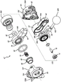
图19是冲击式按摩装置的分解立体图;Figure 19 is an exploded perspective view of the impact massage device;
图20是冲击式按摩装置的传动链部件的一部分的分解立体图;Figure 20 is an exploded perspective view of a portion of the drive chain component of the impact massage device;
图21是冲击式按摩装置的一部分的分解立体图;Figure 21 is an exploded perspective view of a portion of the impact massage device;
图22是冲击式按摩装置的传动系部件的立体图;图23是冲击式按摩装置的推杆组件的立体图;图24是另一冲击式按摩装置的立体图;Figure 22 is a perspective view of the drive train components of the impact massage device; Figure 23 is a perspective view of a push rod assembly of the impact massage device; Figure 24 is a perspective view of another impact massage device;
图25是图24的冲击式按摩装置的侧部立视图;Figure 25 is a side elevational view of the impact massage device of Figure 24;
图26是冲击式按摩装置的侧部立视图,以隐藏线示出了一些内部部件;Figure 26 is a side elevational view of the impact massage device showing some internal components in hidden lines;
图27是冲击式按摩装置的一些内部部件的分解立体图;图28是另一冲击式按摩装置的立体图;以及Figure 27 is an exploded perspective view of some internal components of an impact massage device; Figure 28 is a perspective view of another impact massage device; and
图29是图28的冲击式按摩装置的侧部立视图。FIG. 29 is a side elevational view of the impact massage device of FIG. 28 .
贯穿附图中的若干幅图,相似的附图标记指代相似的部件/部分。Like reference numerals refer to like parts/portions throughout the several figures of the drawings.
具体实施方式Detailed ways
以下的描述和附图是说明性的,且不应被解释为限制性的。多个具体细节被描述,以提供对本公开的透彻理解。然而,在某些实例中,众所周知或常规的细节未被描述,以免模糊描述。在本公开中对一个或另一实施例的引用可以是但不一定是对同一实施例的引用;并且,这样的引用表示的是实施例中的至少一个。The following description and drawings are illustrative and should not be construed as limiting. Numerous specific details are described in order to provide a thorough understanding of the present disclosure. However, in some instances, well-known or conventional details have not been described so as not to obscure the description. References in this disclosure to one or another embodiment may, but are not necessarily, to the same embodiment; and, such references are indicative of at least one of the embodiments.
本说明书中对“一个实施例”或“一实施例”的引用表示的是与实施例相关描述的特定特征、结构或特性被包括在本公开的至少一个实施例中。短语“在一个实施例中”在本说明书中不同地方处的出现并不一定指的是同一实施例,也不一定是与其它实施例互斥的单独的或替代的实施例。此外,各种特征被描述,所述特征可由一些实施例展示而未由其它实施例展示。类似地,各种要求被描述,所述要求可以是对某些实施例的要求而非对其它实施例的要求。References in this specification to "one embodiment" or "an embodiment" mean that a particular feature, structure, or characteristic described in connection with the embodiment is included in at least one embodiment of the present disclosure. The appearances of the phrase "in one embodiment" in various places in this specification are not necessarily referring to the same embodiment nor a separate or alternative embodiment that is mutually exclusive with other embodiments. Additionally, various features are described that may be exhibited by some embodiments and not by others. Similarly, various requirements are described, which may be requirements for some embodiments but not for other embodiments.
本说明书中使用的术语总体上具有它们在本领域中的、在本公开的语境内的和在每个术语所用于的特定语境下的通常含义。用于描述本公开的某些术语在以下或者在本说明书中的其它地方处被论述,从而为从业者提供有关本公开的描述的附加指导。为简便起见,某些术语会比如利用斜体和/或引号被突出显示:突出显示的使用对术语的范围和含义没有影响;术语的范围和含义在相同语境下无论其是否被突出显示都是相同的。将理解的是,相同的事情可能以不止一种方式被述说。Terms used in this specification generally have their ordinary meanings in the art, within the context of this disclosure, and in the specific context in which each term is used. Certain terms used to describe the present disclosure are discussed below or elsewhere in this specification to provide practitioners with additional guidance regarding the description of the present disclosure. For brevity, certain terms are highlighted, such as with italics and/or quotation marks: the use of highlighting has no effect on the scope and meaning of the term; the scope and meaning of the term are in the same context regardless of whether it is highlighted or not. identical. It will be appreciated that the same thing may be said in more than one way.
因此,对于本文中所论述的术语中的任何一个或多个,替代的语言和同义词可被使用。术语在本文中是否被详述或论述没有任何特定的意义。针对某些术语的同义词被提供。对一个或多个同义词的引述并不排除其它同义词的使用。本说明书中任何地方处的示例的使用、包括本文中所论述的任何术语的示例的使用仅为说明性的,并不意图进一步限制本公开的或者任何例示性术语的范围和含义。类似地,本公开并不限于在本说明书中给出的各种实施例。Accordingly, alternative language and synonyms may be used for any one or more of the terms discussed herein. Whether a term is detailed or discussed herein does not have any particular meaning. Synonyms are provided for certain terms. The citation of one or more synonyms does not exclude the use of other synonyms. The use of examples anywhere in this specification, including examples of any terms discussed herein, is illustrative only and is not intended to further limit the scope and meaning of the present disclosure or of any illustrative terms. Similarly, the present disclosure is not limited to the various embodiments presented in this specification.
在无意进一步限制本公开的范围的情况下,根据本公开的实施例的仪器、设备、方法和它们相关的结果的示例在以下给出。注意到,为方便读者,标题或副标题可被用在示例中,这些标题或副标题决不应限制本公开的范围。除非另有定义,否则本文中使用的所有技术术语和科学术语具有与本公开所属领域的普通技术人员通常所理解的相同的含义。在抵触的情况下,将以包含各定义的本文档为准。Without intending to further limit the scope of the present disclosure, examples of instruments, devices, methods and their associated results according to embodiments of the present disclosure are given below. It is noted that headings or subheadings may be used in the examples for the convenience of the reader, and that these headings or subheadings should in no way limit the scope of the present disclosure. Unless otherwise defined, all technical and scientific terms used herein have the same meaning as commonly understood by one of ordinary skill in the art to which this disclosure belongs. In case of conflict, this document, including definitions, will control.
将理解的是,本文中所使用的术语比如“前”、“后”、“顶”、“底”、“侧”、“短”、“长”、“上”、“下”和“以下”仅为了描述的容易且指的是如附图中所示的部件的取向。应理解的是,本文中所描述的部件的任何取向都在本发明的范围内。It will be understood that terms such as "front", "rear", "top", "bottom", "side", "short", "long", "upper", "lower" and "below" are used herein. " is for ease of description only and refers to the orientation of the components as shown in the drawings. It is understood that any orientation of the components described herein is within the scope of the invention.
尽管本文中描述了许多实施例,然而所描述的实施例中的至少一些提供了用于往复式疗治装置的设备、系统和方法。Although many embodiments are described herein, at least some of the described embodiments provide apparatus, systems, and methods for reciprocating therapy devices.
图1-12示出了往复式疗治装置100的实施例。图1-4以示意性的形式示出了所述装置,并且图7-12更加详细地示出了装置100。1-12 illustrate an embodiment of a
图1绘示出往复式疗治装置100的一个实施例的剖切侧视图。也参考图7-8。往复式疗治装置100包括壳体101、动力输入部102、开关104、马达106和被致动输出部108。在一些实施例中,往复式疗治装置100在被致动输出部108处生成运动以用于疗治患者。FIG. 1 depicts a cutaway side view of one embodiment of a
在一个实施例中,壳体101是允许往复式疗治装置100的一个或多个其它部件连接的结构。壳体101可完全或大体上包围一个或多个其它部件。例如,壳体101可以是带有用于其它部件的附接点的形成结构,所述结构在被组装时大体上包围这些部件中的一个或多个。在另一实施例中,壳体101可以允许其它的部件暴露。例如,壳体101可以是开放式框架。在一些实施例中,壳体101包围往复式疗治装置101中的一个或多个部件并使往复式疗治装置101中的一个或多个其它部件暴露。In one embodiment,
如图1、图6和图7中所示,壳体101包括柄120。柄120限定柄轴线122,柄轴线122大体上沿着柄120的最长的尺寸延伸。在一些实施例中,柄120沿着其最长的尺寸是平直或大体平直的,并且柄轴线122延伸通过柄120的中心或大体上通过所述中心。在另一实施例中,柄120沿着其最长的尺寸是弯曲的,并且在柄120的中点处柄轴线122与柄120的弯曲部成切向。在优选的实施例中,柄120具有顶表面120a,所述顶表面被成形使得其可由个人手掌以人体工程学抓握。这为操作装置时的使用者提供舒适。参见例如美国专利号6,105,891,所述美国专利的全部内容以引用的方式并入本文中,其教导了包括符合使用者手掌的相似形状的渔线轮旋钮。如图7中所示,壳体101包括柄120、后部121和下部123,所述下部包括朝向鼓起部150延伸的、向上倾斜的颈部125。柄120、后部121和下部123(包括颈部125)限定中心开口127。As shown in FIGS. 1 , 6 and 7 , the
在一些实施例中,动力输入部102配置为接收从动力源114的动力输入。动力源114可以是能够向马达106供应动力的任何类型的动力源。在一些实施例中,动力输入部102接收从动力源114的电输入。In some embodiments,
例如,动力源114可以是提供电流的电池。在一个实施例中,电池是可充电电池。在一些实施例中,电池可附接到往复式疗治装置100使得包含动力源114的往复式疗治装置100是便携且无绳的。在替代的实施例中,往复式疗治装置100使用外部电池组作为动力源114。For example, the
电池可以是本领域已知的任何类型的电池。例如,电池可包括可充电锂离子(LiIon)基电池。在另一示例中,电池可包括可充电镍氢(NiMH)电池。在仍另一示例中,电池可包括可充电锂-聚合物(LiPo)电池。在一些实施例中,电池包括镍镉(NiCad)电池。在一个实施例中,电池使用非可充电电池。The battery can be any type of battery known in the art. For example, the battery may include a rechargeable lithium-ion (LiIon) based battery. In another example, the battery may include a rechargeable nickel-metal hydride (NiMH) battery. In yet another example, the battery may comprise a rechargeable lithium-polymer (LiPo) battery. In some embodiments, the battery includes a nickel-cadmium (NiCad) battery. In one embodiment, the battery uses a non-rechargeable battery.
在替代的实施例中,动力输入部102包括缆绳以从电缆接收电力。例如,往复式疗治装置100可包括带有插头的缆绳,所述插头配置为与壁装插座触接以提供电力。In an alternate embodiment, the
在另一替代实施例中,动力输入部102为非电气式的。例如,动力输入部102可接收来自压力容器或加压空气网络的加压空气。在另一实施例中,动力输入部102可包括一种或多种反应材料以为往复式疗治装置100的操作提供能量。In another alternative embodiment, the
在一些实施例中,开关104控制向马达106的动力递送。开关104可以是电开关,所述电开关配置为在被激活时允许电流通过。在一些实施例中,开关104是二进制开/关式开关。在另一实施例中,开关104是可变开关(variable switch)。可变开关控制递送到马达106的动力量。通过可变开关104递送到马达106的相对高的动力量导致马达106的增加的速度。通过可变开关104递送到马达106的相对低的动力量导致马达106的减小的速度。在一个实施例中,可变开关104包括可变电阻器,所述可变电阻器允许响应于该开关104的逐渐增加的激活而使有逐渐增加的动力量流到马达106。In some embodiments, switch 104 controls power delivery to
在一些实施例中,开关104可响应于使用者释放开关104而保持处于激活位置。在替代的实施例中,开关104可响应于使用者释放开关104而返回到停用位置。例如,开关104可包括偏压构件比如弹簧,所述弹簧配置为响应于开关104被释放而将开关104推压至停用位置。在某些实施例中,开关104包括多个位置。例如,开关104可包括断开位置、第一激活位置和第二激活位置。开关104可包括这样的一个或多个位置,在所述一个或多个位置中,在没有另外的用户输入的情况下,开关104保持处于该位置,并且开关104可包括这样的一个或多个位置,在所述一个或多个位置中,在没有另外的用户输入的情况下,开关104被偏压成离开该位置。In some embodiments, the
例如,开关104可具有“断开”位置、“接通”位置和“涡轮(turbo)”位置。“接通”和“涡轮”位置可激活不同速率条件下的往复运动,比如在“接通”位置中每分钟2300转以及在“涡轮”位置中每分钟2800转。在被设置成“接通”位置之后,开关104保持处于“接通”位置而无需使用者维持与开关104接触。在被设置成“涡轮”位置之后,开关104会被偏压成返回到“接通”位置,除非使用者在开关104上维持与到“接通”位置的返回相抗的力。For example, switch 104 may have an "off" position, an "on" position, and a "turbo" position. The "on" and "turbo" positions can activate reciprocation at different rates, such as 2300 rpm in the "on" position and 2800 rpm in the "turbo" position. After being set to the "on" position, the
在一个实施例中,马达106将来自动力源102的动力转化成运动。在一些实施例中,马达106是电动机。电动机可以是本领域已知的任何类型的电动机,包括但不限于有刷电机、无刷电机、直流(DC)电机、交流(AC)电机、机械-换向器式电机、电子换向器式电机或者外部换向式电机。In one embodiment, the
在一些实施例中,马达106以这样的速度操作,所述速度可通过开关104的不同激活程度来变化。例如,马达106可以响应于开关104的最大激活而以最大速率操作。马达106可响应于开关104的小于最大的激活而以较低的速率操作。In some embodiments, the
马达106可产生旋转运动。由马达106递送的旋转运动可通过轴116被递送。轴116可绕着轴的轴线126旋转。在一些实施例中,往复式疗治装置100可包括将马达106的旋转运动转化成往复运动的连杆机构。连杆机构的实施例在以下相对于图3A、图3B和图8-10更加详细地示出。
在替代实施例中,马达106可产生往复式运动。例如,马达106可包括响应于压缩空气的输入而往复运动的往复式气缸。In alternate embodiments, the
在一些实施例中,被致动输出部108响应于从马达106的输入而往复运动。例如,马达106可产生旋转运动。齿轮箱可连接到马达106以将旋转运动转化为往复运动。齿轮箱可连接到被致动输出部108。齿轮箱的实施例在以下相对于图4和图8-10更加详细地示出。In some embodiments, the actuated
在一些实施例中,被致动输出部108以约65Hz的速率往复运动。在一些实施例中,被致动输出部108以超过50Hz的速率往复运动。在一些实施例中,往复式疗治装置100提供范围在50Hz与80Hz之间的速率条件下的往复运动。在一些实施例中,被致动输出部108具有在约50Hz与80Hz之间的最大铰接(articulation)速率。在另一实施例中,被致动输出部108具有在30Hz与80Hz之间的铰接速率。在某些实施例中,被致动输出部108具有约37Hz的铰接速率。在一个实施例中,被致动输出部108具有约60Hz的铰接速率。在优选的实施例中,被致动输出部108以在约15Hz与约100Hz之间的频率铰接或往复运动。在更加优选的实施例中,被致动输出部108以在约25Hz与约48Hz之间的频率铰接或往复运动。在最为优选的实施例中,被致动输出部108以在约33Hz与约42Hz之间的频率铰接或往复运动。在指定范围内的任何择选范围也在本发明的范围内。In some embodiments, the actuated
被致动输出部108可移动通过预定的往复运动范围。例如,被致动输出部108可配置为具有二分之一英寸的振幅。在另一实施例中,被致动输出部108可配置为具有四分之一英寸的振幅。如本领域技术人员将理解的,被致动输出部108可配置为具有被认为有诊疗益处的任何振幅。The actuated
在一些实施例中,被致动输出部108会是可通过可变的往复运动范围调节的。例如,往复式疗治装置100可包括这样的输入,所述输入用以调节从四分之一英寸至高达一英寸的范围的往复运动振幅。在优选实施例中,被致动输出部108移动通过在约0.15英寸与约1.0英寸之间的振幅。在更加优选的实施例中,被致动输出部108以在约0.23英寸和约0.70英寸之间的频率铰接或往复运动。在最为优选的实施例中,被致动输出部108以在约0.35英寸与约0.65英寸之间的频率铰接或往复运动。在指定范围内的任何择选范围也在本发明的范围内。In some embodiments, the actuated
将理解的是,装置在组合的频率和振幅范围条件下操作最为高效。在开发本发明时,发明人确定,如果频率和振幅高于以上所述的范围,则装置会导致疼痛,而如果低于所述范围,则装置是无效的且并不提供有效的诊疗性缓解或按摩。仅当装置在所公开的频率和振幅范围的组合内操作时,装置将有效且诊疗上有益的疗治提供到被装置靶向的肌肉。It will be appreciated that the device operates most efficiently at a combined frequency and amplitude range. In developing the present invention, the inventors determined that if the frequency and amplitude are above the ranges stated above, the device causes pain, and if it is below the ranges, the device is ineffective and does not provide effective therapeutic relief or massage. The device provides effective and therapeutically beneficial therapy to the muscle targeted by the device only when the device operates within the disclosed combinations of frequency and amplitude ranges.
在某些实施例中,往复式疗治装置100包括这样的一个或多个部件,所述一个或多个部件用以响应于在动力输入部102处提供的变化的动力程度来调节被致动输出部108的铰接速率。例如,往复式疗治装置100可包括电压调节器(未示出)以在输入电压范围内提供大致恒定的电压到马达106。在另一实施例中,提供到马达106的电流可被调节。在一些实施例中,往复式疗治装置100的操作可响应于输入电压低于预设值而被约束。In certain embodiments, the
在一些实施例中,被致动输出部108包括用于附件连接的连接器110。在一些实施例中,被致动输出部108包括用于将附件固定在连接座110中的固定机构112。连接器110可以是能够保持附件的任何类型的结构,比如带有闩锁的座、螺纹连接器等。In some embodiments, the actuated
例如,固定机构112可包括偏压结构比如弹簧,以偏压固定机构112朝向锁定位置。在锁定位置中,固定机构112可约束附件的移除。偏压结构可通过使用者被铰接以使固定机构112朝向解锁位置移动。在解锁位置中,固定机构112可允许附件移除。For example, the
在一些实施例中,固定机构112包括与附件上的键相互作用的键槽。键槽可通过固定机构112的铰接而选择性地打开和关闭。附件的移除可响应于键槽被关闭而受约束。In some embodiments, the
如图9中所示,在另一实施例中,连接器110可以是阳性连接器并可包括与疗治结构204配合的至少一个(且优选地两个)向外偏压的滚珠轴承110a。As shown in FIG. 9 , in another embodiment, the
在某些实施例中,被致动输出部108沿着直线或大致直线的路径往复运动。由被致动输出部108行进过的路径限定往复运动轴线124。在某些实施例中,往复运动轴线124延伸通过被致动输出部108的一个或多个部件的几何中心。In certain embodiments, the actuated
在一些实施例中,被致动输出部108包括在壳体101的一部分与突出部分(比如连接机构112)之间的安全延伸部128。安全延伸部128为被致动输出部108的区域提供大致恒定的截面轮廓。安全延伸部128降低在被致动输出部108致动时的夹挤身体部位(比如手指)的风险。安全延伸部128可被限定为被致动输出部108的这样的区域,即在任何非往复运动的部件(比如壳体101)与被致动输出部108的具有相对大的或延伸的截面的任何部件(比如连接机构)之间的区域。在一个实施例中,当在被致动输出部108充分缩回时测量时,安全延伸部128的沿着往复运动轴线124的长度比普通使用者的各手指中的任何的宽度都大。在一些实施例中,当在被致动输出部108充分缩回时测量时,安全延伸部128的沿着往复运动轴线124的长度为至少18毫米。在一些实施例中,马达106连接到壳体101使得轴旋转轴线126平行于由柄轴线122和往复运动轴线124限定的平面。在一个实施例中,马达106连接到壳体101使得轴旋转轴线126与由柄轴线122和往复运动轴线124限定的平面共面。In some embodiments, the actuated
图2绘示出图1的往复式疗治装置100的一个实施例的侧视图。往复式疗治装置100包括附件202、疗治结构204和歇置表面206。在一个实施例中,往复式疗治装置100在疗治结构204处生成往复运动以用于疗治患者。FIG. 2 depicts a side view of one embodiment of the
附件202可以是可互换的、使用者可选择的部件,所述部件可连接到被致动输出部108。附件202可包括设计为与患者相互作用的疗治结构204。The
歇置表面206为设置在壳体101上的表面。歇置表面206配置成使得,当往复式疗治装置100具有被置于平坦、水平表面上的歇置表面206时,往复式疗治装置100能够在无外力施加的情况下歇置于该位置中。换言之,当如以上所描述地歇置时,从往复式疗治装置100的重心向下绘制的线条穿过歇置表面206。如该段落中所使用的,“向下”指的是重力对具有质量的物体施加力的方向。The
图3A、图3B和图8-11E绘示出用于往复式疗治装置100的致动部件300的实施例的视图。致动部件300总体包括马达106、柔性轴阻尼器302、其上带有轴齿轮117的轴116、齿轮构件304、离心触接部306、往复器触接部308、往复器轴310和被致动输出部108。马达106、轴116和被致动输出部108与以上关于图1所描述的带有相似标号的部件类似。致动部件300创建在被致动输出部108处被递送的运动。FIGS. 3A , 3B, and 8-11E depict views of an embodiment of an
在一个实施例中,从马达106经由轴116和齿轮107递送旋转运动。在某些实施例中,马达106通过柔性轴阻尼器302连接到致动部件300的其它部件。柔性轴阻尼器302包括柔性材料(compliant material),所述柔性材料配置为吸收由致动部件300生成的振动。柔性轴阻尼器302可传递由马达106生成的旋转运动同时在振动荷载下变形、从而吸收或部分地吸收和减少往复式疗治装置100中的振动。柔性轴阻尼器302可包括能够吸收振动的任何材料。在一些实施例中,柔性轴阻尼器302包括聚合物。例如,柔性轴阻尼器302可包括柔韧的聚合物。在一个示例中,柔性轴阻尼器302包括聚氨酯发泡物/发泡体、热塑性弹性体(“TPE”),包括但不限于苯乙烯嵌段共聚物(TPE-s)、聚烯烃混合物(TPE-o)、弹性体合金(TPE-v或TPV)、热塑性聚氨酯(TPU)、热塑性共聚酯或热塑性聚酰胺。在另一个示例中,柔性轴阻尼器302可包括聚氯乙烯(PVC)、低硬度PVC或尿烷。In one embodiment, rotational motion is delivered from
在一个实施例中,齿轮构件304接收由马达106生成的旋转运动。在一些实施例中,齿轮构件304响应于马达106的旋转而旋转。在一个实施例中,齿轮构件304绕着与轴旋转轴线126垂直的旋转轴线316旋转。例如,齿轮构件304可以是锥齿轮、螺旋锥齿轮或者准双曲面齿轮的部分。这样的齿轮可具有使旋转轴线旋转90度的作用。In one embodiment, the
在一些实施例中,齿轮构件304包括离心触接部306。离心触接部306在齿轮构件304的表面上设置成使得,离心触接部或离心触接部的中心处在不在齿轮旋转轴线316上的位置处。换言之,如果齿轮构件304是圆的,那么离心触接部306不设置在齿轮构件304的中心处。In some embodiments,
响应于齿轮构件304的旋转及随后的离心触接部306的运动,往复器触接部308将离心触接部306相对于往复器触接部308的直线运动约束到与往复运动轴线124和齿轮旋转轴线316两者均垂直的方向。In response to rotation of
换言之,在齿轮构件304旋转时,离心触接部306自由在往复器触接部308内以从一边到另一边的方式(side-to-side)滑动。注意到,除了相对于往复器触接部308滑动之外,离心触接部306也可旋转。In other words,
如图9中所示,在优选的实施例中,离心触接部306包括销22和套筒24。销22被接收在齿轮构件304中限定的或穿过齿轮构件304限定的偏心开口26中。套筒24被接收在往复器轴310的端部或头36中限定的细长开口34中。As shown in FIG. 9 , in the preferred embodiment, the
在一个实施例中,离心触接部306与往复器触接部或容置构件308触接。容置构件308容置往复器轴310的头36并限定往复运动空间38,往复器轴310的头36和离心触接部件306可在所述往复运动空间中往复运动。容置构件308包括腿40,腿各自包括内表面,在所述内表面中限定台阶42。在各腿之间的较大尺寸限定用于头36往复运动的空间,并且在各腿之间的较小尺寸限定用于套筒往复运动的空间。在优选的实施例中,往复器轴310为L形的或者包括臂部,使得往复器轴沿着往复运动轴线连接到被致动输出部或轴108。In one embodiment,
在一些实施例中,离心触接部306与往复器触接部308之间的相互作用的作用是将在齿轮构件304处的旋转运动转化成在往复器轴310处的往复式直线运动。往复器轴310将往复式直线运动传递至被致动输出部108。In some embodiments, the interaction between
如图3B和图9中所示,在一个实施例中,齿轮构件304包括配重312。配重312配置为对抗由被致动输出部108的往复式运动生成的惯性力。配重312可在齿轮构件304上定位成使得配重的质心314未沿着齿轮旋转轴线316定位。在某些实施例中,从齿轮旋转轴线316到配重312的质心314的第一方向可以是与从齿轮旋转轴线316到离心触接部306的中心的第二方向相反的方向。优选地,配重312位于齿轮构件304的一侧上,并且齿轮齿位于相反侧上。在另一实施例中,齿轮和配重可以是分开的部件。As shown in FIGS. 3B and 9 , in one embodiment, the
在一些实施例中,在往复式疗治装置100操作时,配重312至少施加这样的力分量,即所述力分量沿着与由往复器触接部308对离心触接部306施加的反作用力相反的方向。换言之,配重312可用于抵消由往复运动的部件生成的惯性力并减少由被致动输出部108的往复运动造成的振动。In some embodiments, when reciprocating
在一些实施例中,配重312可尺寸设计为匹配往复式疗治装置100的往复运动部件。例如,配重312可具有与往复运动部件相似的质量,所述往复运动部件包括例如往复器轴310、被致动输出部108和附件202。在另一实施例中,配重具有在45克与55克之间的质量。In some embodiments, the
图11A示出了处于延伸位置的往复器轴310,并且图11C示出了处于缩回位置的往复器轴310。图11B和图11D示出了处于缩回位置与延伸位置之间中的往复器轴。注意销22和套筒24(离心触接部)如何在细长开口34内移动以及容置构件308如何保持往复器轴310的头36直线地运动。图11E示出了处于延伸位置、但旋转组件47已被旋转之后的往复器轴310,如以下论述的。FIG. 11A shows the
如图8-10中所示,致动部件300包括导引构件30,所述导引构件包括一中心开口,往复器轴310延伸通过所述中心开口。导引构件30被容纳在旋转壳体44中并在往复器轴于其中移动时保持静止。在优选的实施例中,致动部件300还包括销或杆轴16,齿轮构件304使轴承14和阻尼环28在所述销或杆轴上旋转,以便衰减壳体与金属部件之间的连接。As shown in Figures 8-10, the
图4和图8-11E绘示出往复式疗治装置100的致动部件300的实施例。致动部件包括马达106、齿轮构件304、往复器轴310、一个或多个柔性阻尼块402、以及齿轮箱404。致动部件300通过往复器轴310提供往复式运动并管理向壳体101传递的振动。4 and 8-11E illustrate an embodiment of the actuating
一个或多个柔性阻尼块402管理从致动部件300传导到壳体101的振动。一个或多个柔性阻尼块402可设置在致动部件300与壳体101之间。One or more flexible damping
一个或多个柔性阻尼块402可包括能够吸收振动的任何材料。在一些实施例中,一个或多个柔性阻尼块402包括聚合物。例如,一个或多个柔性阻尼块402可包括柔韧的聚合物。在一个示例中,一个或多个柔性阻尼块402包括聚氨酯发泡物/发泡体、热塑性弹性体(“TPE”),包括但不限于苯乙烯嵌段共聚物(TPE-s)、聚烯烃混合物(TPE-o)、弹性体合金(TPE-v或TPV)、热塑性聚氨酯(TPU)、热塑性共聚酯或热塑性聚酰胺。在另一示例中,一个或多个柔性阻尼块402可包括聚氯乙烯(PVC)、低硬度PVC或尿烷。The one or more flexible damping
在一个实施例中,齿轮箱404包括齿轮构件304和往复器310。齿轮箱404可提供用于齿轮构件304和往复器310的安装点。齿轮箱404可将齿轮构件304和往复器的运动约束到某些方向或旋转轴线。齿轮箱404可安装到壳体101。在一些实施例中,齿轮箱404通过一个或多个柔性阻尼块402与壳体101分开。In one embodiment,
如图11C和图12中所示,在一些实施例中,被致动输出部108和关联的部件可相对于壳体101旋转。被致动输出部108可相对于壳体101绕着输出旋转轴线旋转。在某些实施例中,输出旋转轴线平行于齿轮旋转轴线316。在一个实施例中,输出旋转轴线与齿轮旋转轴线316伴生(concomitant)。例如,被致动输出部108、往复器310和往复器触接部308可以是可绕着齿轮旋转轴线316选择性地旋转。As shown in FIGS. 11C and 12 , in some embodiments, the actuated
在一个实施例中,被致动输出部108的旋转可被选择性锁定并由使用者解锁。例如,使用者可解锁被致动输出部108的旋转、使被致动输出部108旋转到相对于壳体101的期望位置、锁定被致动输出部108的旋转以及操作往复式疗治装置100。In one embodiment, rotation of the actuated
如图12中所示,在优选的实施例中,旋转组件47包括旋转壳体44(其包括第一旋转壳体半部44a和第二旋转壳体半部44b)、其上具有齿48的铰接锁或按钮46、以及接触座置表面43的弹簧18。齿轮构件304、往复器轴310、杆轴16、齿轮箱404的一部分和轴承14全部被容纳在旋转壳体44中。组件还包括齿轮箱盖56和阻尼环52。按钮As shown in FIG. 12, in the preferred embodiment, the rotating assembly 47 includes a rotating housing 44 (which includes a first
46通过弹簧18被向外偏压到齿48与壳体101中限定的齿50接合的位置。按钮46可在齿48与齿50接合的第一位置和齿48与第二旋转壳体半部44b中的齿54接合的第二位置之间移动。当按钮46处于第一位置时,旋转组件47无法旋转。当按钮被推压到第二位置时,齿48与齿50脱开接合并接合旋转壳体44中的齿54,从而允许整个旋转组件47旋转。旋转壳体44包括设置在壳体中的主体部分62和延伸通过旋转空间60并在壳体外侧延伸的臂部64。臂部64在壳体101中限定的旋转空间60内旋转。将理解的是,当旋转发生时,齿轮构件304和齿轮箱404并不旋转(比较图11A-11D与图11E),但是容置构件308与被致动输出部108一起确实旋转。如图8、图9和图12中所示,壳体101包括鼓起部150,所述鼓起部具有第一鼓起部表面150a和第二鼓起部表面150b,所述第一鼓起部表面定位在使壳体101分叉的平面(本文中也称为“壳体平面”)的第一侧上,并且第二鼓起部表面定位在壳体平面的第二侧上。柄120包括定位在壳体平面的第一侧上的第一柄侧表面120b和定位在壳体平面的第二侧上的第二柄侧表面120c。第一鼓起部表面150a比第一柄侧表面120b距壳体平面更远定位,并且第二鼓起部表面150b比第二柄侧表面120c距壳体平面更远定位。46 is biased outwardly by
图5绘示出流程图,示出了图1的往复式疗治装置的制造方法的一个实施例。FIG. 5 depicts a flow chart illustrating one embodiment of a method of manufacturing the reciprocating therapy device of FIG. 1 .
图5和图6是流程图,绘示了用于制造图1的往复式疗治装置100的方法500和使用图1的往复式疗治装置100的方法600的实施例。在某些实施例中,方法500、600是使用本文中所描述的系统和设备的方法,并将参考这些附图来论述。然而,方法500、600也可独立于这些附图进行,且并不意图被特定地限制于以上针对这些附图论述的特定实施例。5 and 6 are flowcharts illustrating embodiments of a
如图5中所示,用于往复式疗治装置100的制造方法500被示出。在制造方法500的一个实施例中,壳体101被提供502。壳体101可包括柄120,并且柄120可限定柄轴线122。马达106被连接504到壳体101。马达106可提供旋转运动。As shown in FIG. 5, a
在一些实施例中,被致动输出部108可操作地连接506到马达106。被致动输出部108可响应于马达106的激活而往复运动。被致动输出部108的往复运动可沿着往复运动轴线124。In some embodiments, the actuated
在一些实施例中,马达106包括轴116。轴116可绕着轴旋转轴线126旋转。轴旋转轴线126可平行于柄轴线122和往复运动轴线124所位于的平面。In some embodiments, the
如图6中所示,用于往复式疗治装置100的使用方法600被示出。在使用方法600的一个实施例中,力通过往复型疗治装置100的被致动输出部108施加602到身体部位。往复型疗治装置100可包括壳体As shown in FIG. 6, a
101。壳体101可包括设置在壳体101上的柄120。柄120可限定柄轴线122。101. The
往复型疗治装置100可还包括连接到壳体101的马达106。被致动输出部108可以可操作地连接到马达106。被致动输出部108可配置为响应于马达106的激活而往复运动。被致动输出部108的往复运动可沿着往复运动轴线124。The
马达106可包括轴116,所述轴具有轴旋转轴线126。轴旋转轴线126可平行于柄轴线122和往复运动轴线124所位于的平面。The
图14-27示出了本发明的另外的实施例。图14-27的往复型疗治装置或冲击式按摩装置中的许多部件与以上针对往复型疗治装置100所论述的那些部件相同或相似。相应地,下文中的描述着重于不相同的部件。14-27 illustrate further embodiments of the present invention. Many of the components in the reciprocating therapy device or percussion massage device of FIGS. 14-27 are the same as or similar to those discussed above for the
图14-23示出了冲击式按摩装置212的实施例,所述冲击式按摩装置包括可充电电池(及可更换或可移除电池)114。装置212商业上被称为G3PRO。如图14-15中所示,在优选的实施例中,冲击式按摩装置212包括三个柄部(本文中也称为第一柄部143、第二柄部145和第三柄部147),所述三个柄部协作而限定中心开口或柄开口149。所有柄部都足够长,从而它们被配置成使得个人能够抓握该特定的柄部来利用装置。抓握不同柄部的能力允许个人(当将装置用在他们自己的身体上时)将装置用在不同的身体部位上和从不同角度来使用装置,从而提供伸抵诸如背部之类的不利用三个柄部可能无法实现的身体部位的能力。FIGS. 14-23 illustrate an embodiment of an
如图14中所示,第一柄部143限定第一柄部轴线A1,第二柄部145限定第二柄部轴线A2,并且第三柄部147限定第三柄部轴线A3,这些轴线协作而形成三角形。在优选的实施例中,电池114被容纳在第二柄部145中并且马达106被容纳在第三柄部147中。As shown in FIG. 14, the
图16-18示出了使用者的手抓握不同的柄部。第一、第二和第三柄部中的每个的长度都足够长,使得手大的个人能够以至少三到四根手指延伸通过柄开口的方式舒适地抓握每个柄部,如图16-18中示出的。在优选的实施例中,第一柄部143具有内边缘143a,第二柄部145具有内边缘145a,并且第三柄部147具有内边缘147a,所有这些内边缘协作而至少部分地限定柄开口149。如图14中所示,在优选的实施例中,第一柄部143包括指用突起151,所述指用突起包括指用表面151a,所述指用表面在第一柄部的内边缘143a与第三柄部147的内边缘147a之间延伸且至少部分地限定柄开口149。如图16中所示,在使用中,使用者可将他们的食指抵靠指用表面151a置放。指用突起和表面提供反馈点或支撑表面,使得当使用者将他们的食指抵靠所述表面置放时,所述表面有助于使用者对利用装置的控制和舒适。在优选的实施例中,指用表面151a的至少一部分是平直的,如图14中所示(与柄开口149的其它“角部”为圆角的截然不同。16-18 show a user's hand grasping different handles. Each of the first, second, and third handles is long enough to allow a person with large hands to comfortably grasp each handle with at least three to four fingers extending through the handle opening, as shown in the figure. 16-18 shown. In a preferred embodiment, the
图14A示出了柄开口149的内表面的优选尺寸。将理解的是,所述内表面包括一系列平坦和弯曲的表面。H1是第一柄部143的内边缘143a的尺寸(第一柄部长度)。H2是第二柄部145f的内边缘145a的尺寸(第二柄部长度)。H3是第三柄部147的内边缘147a的尺寸(第三柄部长度)。H4是指用表面151a的尺寸(指用突起长度)。R1是在内边缘143a和145a之间的半径的尺寸,并且R2是在内边缘145a和147a之间的半径的尺寸。在优选的实施例中,H1是约94mm,H2是约66mm,H3是约96mm,H4是约12mm,R1是约6.5mm,并且R2是约6.5mm,这提供大约10.2mm的弧长。在本文中的语境下,“约”是在5mm内。在优选的实施例中,柄开口的内边缘的长度是约289mm。利用H1、H2、H3、H4、R1和R2的任何组合,柄开口的内边缘的长度可在约260mm与约320mm之间。将理解的是,这些尺寸可被优化以便第95百分位的男性可以以三根且优选地四根手指延伸通过柄开口的方式抓握三个柄部中的任何来利用装置。将理解的是,表面R1和R2中的任何或全部可被考虑为三个相邻的柄部中的任何的一部分。如图14和图14A中所示,在指用表面151a为平直的情况下,第一柄部内表面、第二柄部内表面、第三柄部内表面和指用表面协作而限定在每个平直表面之间具有半径或圆角边缘的四边形。Figure 14A shows the preferred dimensions of the inner surface of the
装置212还包括多个速度设定(优选地1500和2400PRM,但可以是其中教导的任何速度或频率)。此外,本领域普通技术人员将理解的是,尽管RPM被列举为特定的数字,然而由于制造公差,在使用期间RPM会振荡。例如,在2400RPM的设定下,RPM实际上会在2260与2640之间振荡。
图19-23示出了在图14-18和图24-27中示出的疗治装置212(208和210)中包括的一些内部部件和外部部件。如图19中所示,冲击式按摩装置212包括壳体101,所述壳体包括第一和第二壳体半部103。外盖213和顶盖215被接收在第一和第二壳体半部103上并经由突片105或其它机构或附接方法(比如,螺纹紧固件、夹具、粘合剂、声波焊接等)连接到所述第一和第二壳体半部。冲击式按摩装置212还包括绷子(tambour)门217、电池114、内悬置环219和容纳齿轮箱404的旋转壳体44(具有第一旋转壳体半部44a和第二旋转壳体半部44b)。Figures 19-23 illustrate some of the internal and external components included in the treatment device 212 (208 and 210) shown in Figures 14-18 and 24-27. As shown in FIG. 19 , the
如图20中所示,装置包括小齿轮联接组件216(类似于以上描述的柔性轴阻尼器302),所述小齿轮联接组件设置在马达与小齿轮或轴齿轮117(位于轴或小齿轮轴116上)之间。小齿轮联接组件216用于将马达联接到齿轮箱以便扭矩被充分传递,使得没有径向移动且振动和噪声被最小化。小齿轮联接组件216优选包括三个单独的部件,即下连接器218、十字形联接部220和上连接器222。在优选的实施例中,下连接器218包括主体部分218,所述主体部分限定接收马达轴248的中心开口218b和从主体部分218a向外延伸的第一和第二下连接器臂218c。上连接器222包括主体部分222a,所述主体部分限定接收小齿轮轴117的中心开口222b和从主体部分222a向外延伸的第一和第二上连接器臂222c。优选地,十字形联接部220包括径向延伸肋220a,在所述径向延伸肋之间限定通道220b。第一和第二下连接器构件218c和第一和第二上连接器构件222c尺寸及形状设计为在通道220b中被接收以操作地接合所述径向延伸肋。在使用中,马达轴248旋转小齿轮联接组件,小齿轮联接组件旋转小齿轮轴117。这些部件一起工作来减少噪声和振动。在优选的实施例中,下连接器和上连接器由塑料制成,并且十字形联接部由弹性体制成。在优选的实施例中,十字形联接部220由橡胶制成,所述橡胶包括这样的硬度:其中由马达生成的振动被隔绝,同时保持强度并高效地传递扭矩(而没有显著的能量耗散)。然而,材料不是对本发明的限制。As shown in Figure 20, the device includes a pinion coupling assembly 216 (similar to the
在优选的实施例中,小齿轮轴116被接收在轴承224和225中并延伸通过所述轴承。优选地,轴承224包括滚珠轴承(并提供径向支撑),并且轴承225包括滚针轴承(并提供径向支撑,但可承受较高温度)。小齿轮联接组件216被容纳在马达安装件250中,所述马达安装件连接到马达106并且马达轴248延伸通过所述马达安装件。马达安装件250连接到齿轮箱安装件252,如图22中示出的。In the preferred embodiment, the
如图20-22中所示,在一个实施例中,齿轮箱404包括齿轮构件304和往复器或推杆230/310。齿轮箱404可提供用于齿轮构件304和往复器310的安装点。齿轮箱404可将齿轮构件304和往复器的运动约束到某些方向或旋转轴线。齿轮箱404可安装到壳体101。在一些实施例中,齿轮箱404通过一个或多个柔性阻尼块402与壳体101分开。As shown in Figures 20-22, in one embodiment, the
如图19和图21中所示,在优选的实施例中,为了防止齿轮箱将振动传递到壳体,橡胶盖可被提供。另外的内悬置环219使齿轮箱的振动与柄和疗治结构隔绝。优选地,环219由弹性体制成并充当缓冲部以衰减在旋转壳体与壳体101之间的振动。在优选的实施例中,内悬置环219围绕主体部分62的外径向表面(参见图21中的座表面523)。As shown in Figures 19 and 21, in a preferred embodiment, in order to prevent the gearbox from transmitting vibrations to the housing, a rubber cover may be provided. An additional
在一个实施例中,被致动输出部或轴108的旋转可被选择性地锁定和由使用者解锁。例如,使用者可解锁轴108的旋转、将被致动输出部108旋转到相对于壳体101的期望位置、锁定被致动输出部108的旋转以及操作往复式疗治装置100。图21示出了允许旋转壳体44连同推杆组件108及相关部件旋转的部件。按钮515包括径向延伸齿515a并通过弹簧519被向外偏压,所述弹簧围绕间隔件518(其优选由发泡物/发泡体制成)并座置在所述间隔件上。弹簧519抵靠阻尼构件520和517座置,所述阻尼构件优选由橡胶制成以衰减弹簧519的任何振动。组件还包括齿轮箱盖525和阻尼环521。按钮515被弹簧519向外偏压到齿515a与齿516a接合的位置,所述齿516a是连接到壳体101的限定的圈516。优选地,圈516包括内塑料环516b和外塑料环516c,在所述内塑料环与外塑料环之间夹持橡胶环516d以帮助衰减振动并减少噪声。按钮515可在齿515a与齿516a接合的第一位置与齿515未与齿516a接合的第二位置之间移动。当按钮515处于第一位置时,旋转组件47无法旋转。当按钮被推压到第二位置时,齿515a与齿516a脱开接合,由此允许整个旋转组件47旋转。旋转壳体44包括设置在壳体中的主体部分62和延伸通过旋转空间并在壳体外侧延伸的臂部64。臂部64在壳体101中限定的旋转空间内旋转。如图15中所示,在优选的实施例中,装置212包括绷子门217,在旋转组件被从图14中所示的位置移动到图15中所示的位置时,所述绷子门展开。绷子门217覆盖槽214。如图15中所示,臂盖524覆盖旋转壳体44的臂部64。In one embodiment, rotation of the actuated output or
如图22中所示,齿轮箱壳体404包括限定于其中的用于推杆组件108的间隙槽214。槽214被提供,从而推杆组件108可自由移动并允许旋转壳体44铰接。间隙槽214具有第一端部214a和第二端部214b。如图22中所示,推杆组件108延伸通过间隙槽214。将理解的是,当旋转壳体44从第一位置被旋转到第二位置时,推杆组件108在间隙槽214内从间隙槽的第一端部移动到第二端部。As shown in FIG. 22 , the
如图21-23中所示,在优选的实施例中,推杆组件或输出轴108包括两个半部或杆,所述两个半部或杆之间具有适配器构件226以同样帮助减少噪声和振动。适配器构件226隔绝齿轮箱中生成的振动并防止振动顺着轴传递到疗治结构。适配器构件226可包括防旋转突片以在使用期间保护推杆免遭使用者施加的扭矩。输出轴108的第一杆部230(推杆或往复器310)在其端部上包括接收枢轴销234的开口232。第一杆部230与适配器构件226之间的连接部包括带有销234和用以衰减振动的弹性体材料的套管227。第一杆部230的包括开口232的端部被接收在适配器构件226中的袋部229中。销234延伸通过在适配器构件226的侧壁中的开口、通过套管227并通过开口232,从而将第一杆部230固定到适配器构件226。适配器构件226包括从之延伸的突起231,所述突起被接收在第二杆部236的端部中的开口233中以将适配器构件226连接到第二杆部236。在另一实施例中,第二杆部236的端部可被接收在适配器构件226中的开口中。在使用中,袋部229的顶部开口的尺寸允许当开口232在销234上枢转并且第一杆部231往复运动时第一杆部从一边移动到另一边。这转变成第二杆部236的直线往复运动。由于套管227包括至少一些弹性体材料,因此当推杆组件108往复运动时振动被衰减(且噪声减少)。As shown in Figures 21-23, in a preferred embodiment, the push rod assembly or
环526座置在臂部64的底部上并围绕所述臂部的底部(参见图21中的座64a)以帮助将第一壳体半部44a和第二壳体半部44b保持在一起。垫圈或导引构件527被接收在旋转壳体44中并为往复运动的推杆组件或输出轴108提供稳定和路径。A
如图22中所示,在该实施例中,第一杆部230或推杆组件108延伸通过间隙槽214。将理解的是,术语推杆组件包括本文中所描述的任何实施例并可包括带有允许两个半部之间枢转的适配器构件的轴或可包括未包括任何枢转部的单个轴。As shown in FIG. 22 , in this embodiment, the
如图22-23中所示,在优选的实施例中,阳性连接器110在与阴性开口中的槽匹配的每个滚珠上方包括对准突片497。这些突片497有助于与疗治结构的恰当对准。参见美国专利申请号2019/0017528,所述美国专利申请的全部内容以引用的方式并入本文中。As shown in Figures 22-23, in a preferred embodiment, the
图24-29示出了与以上的冲击式按摩装置212相似、但不带有旋转组件的冲击式按摩装置的实施例。图24-27中所示的装置商业上被称为G3。图28-29中所示的装置210商业上被称为LIV。如图26中所示,在优选的实施例中,开关104包括与之关联的开关电子器件575。开关电子器件575可包括印刷电路板(PCB)和用以允许开关104激活马达106和改变马达的速度、使装置接通和关闭等等其它任务的其它部件。如图26中所示,在优选的实施例中,马达106被容纳在第三柄部147中,电池114被容纳在第二柄部145中,并且开关电子器件575被容纳在第一柄部143中。该配置结构也应用于装置210和212。24-29 illustrate an embodiment of an impact massage device similar to the
图27示出了缓冲构件577,缓冲构件围绕齿轮箱404并帮助衰减和减少由齿轮箱中的部件生成的噪声和振动。缓冲构件577与装置212中的内悬置环219相似。然而,缓冲构件577更厚并且由于未包括装置208和210中的旋转壳体而无需旋转。缓冲构件577包括在其中的切口或通道579,以允许部件比如推杆组件和小齿轮轴的间隙。Figure 27 shows a damping
尽管以特定的顺序示出和描述了本文中的方法的操作,然而每种方法的操作顺序可被变更,使得某些操作可以以反向的顺序来实施或者使得某些操作可至少部分地与其它操作同时实施。在另一实施例中,相异操作的指令或子操作可以以间歇性的和/或交替的方式执行。Although the operations of the methods herein are shown and described in a particular order, the order of operations of each method may be altered such that certain operations may be performed in the reverse order or such that certain operations may be performed at least in part with Other operations are performed simultaneously. In another embodiment, instructions or sub-operations of distinct operations may be performed in an intermittent and/or alternating fashion.
除非上下文另外清楚地要求,否则贯穿本说明书和权利要求书,词语“包括”、“包含”等应以包含性的意义而非排除性或穷尽性的意义来解读;也就是说,以“包括但不限于”的意义来解读。如本文中所使用的,术语“连接”、“联接”或其任何变型表示的是两个或更多个元件之间的直接或间接的任何连接或联接;元件之间的连接的联接可以是物理的、逻辑的或它们的组合。另外,词语“本文中”、“以上”、“以下”及类似意思的词语当被用在本申请中时将指的是本申请整体而不是本申请的任何特定部分。在语境允许的条件下,在以上具体实施方式中使用单数或复数的词语也可以分别包括复数和单数。在对两项或更多项的列举的引用中词语“或”涵盖对该词语的以下所有解读:列举中的任何项,列举中的所有项,以及列举中的各项的任何组合。Unless the context clearly requires otherwise, throughout this specification and the claims, the words "comprising", "comprising" and the like are to be read in an inclusive rather than an exclusive or exhaustive sense; that is, the words "including" but not limited to". As used herein, the terms "connected," "coupled," or any variation thereof mean any connection or coupling, direct or indirect, between two or more elements; the coupling of a connection between elements may be Physical, logical or a combination of these. Additionally, the words "herein," "above," "below," and words of similar import when used in this application will refer to this application as a whole and not to any particular portions of this application. Where the context permits, words using the singular or plural in the above detailed description may also include the plural and singular, respectively. The word "or" in a reference to a list of two or more items encompasses all of the following readings of the word: any item from the list, all items from the list, and any combination of items from the list.
对本公开的实施例的以上详细描述并不意图是穷尽性的或者意图将教导限于以上所公开的确切形式。尽管出于说明性的目的在以上描述了本公开的特定实施例和对本公开的示例,然而如相关领域的技术人员将理解的,在本公开的范围内,各种等同修改也是可行的。例如,尽管过程或模块被以给定的顺序呈现,然而替代的实施例可以以不同的顺序来实施具有步骤的例程或采用具有模块的系统,并且一些过程或模块可被删除、移动、添加、细分、组合和/或修改以提供替代例或子组合。这些过程或模块中的每个可以以各种各样不同的方式被执行。而且,尽管过程或模块有时候被示出为串联实施,然而这些过程或模块也可替代地并行实施或可在不同的时间实施。另外,本文中提及的任何特定的数字仅仅是示例:替代的实施方式可采用不同的值或范围。The above detailed description of embodiments of the present disclosure is not intended to be exhaustive or to limit the teachings to the precise forms disclosed above. While specific embodiments of, and examples for, the disclosure are described above for illustrative purposes, various equivalent modifications are possible within the scope of the disclosure, as those skilled in the relevant art will appreciate. For example, although procedures or modules are presented in a given order, alternative embodiments may implement a routine with steps or employ a system with modules in a different order, and some procedures or modules may be deleted, moved, added , subdivide, combine and/or modify to provide alternatives or subcombinations. Each of these processes or modules can be performed in a variety of different ways. Also, although processes or modules are sometimes shown as being implemented in series, these processes or modules may alternatively be implemented in parallel or may be implemented at different times. Additionally, any specific numbers mentioned herein are examples only: alternative embodiments may employ different values or ranges.
对本公开的实施例的以上详细描述并不意图是穷尽性的或意图将教导限于以上所公开的确切形式。尽管出于说明性的目的在以上描述了本公开的特定实施例和对本公开的示例,然而如相关领域的技术人员将理解的,在本公开的范围内,各种等同的修改也是可行的。另外,本文中所提及的任何特定的数字仅仅是示例:替代的实施方式可采用不同的值、量度或范围。将理解的是,本文中给出的任何尺寸仅仅是示例性的,并且这些尺寸或描述中没有任何者对本发明是限制性的。The above detailed description of embodiments of the present disclosure is not intended to be exhaustive or to limit the teachings to the precise forms disclosed above. While specific embodiments of, and examples for, the disclosure are described above for illustrative purposes, various equivalent modifications are possible within the scope of the disclosure, as those skilled in the relevant art will understand. Additionally, any specific numbers mentioned herein are merely examples: alternative embodiments may employ different values, measures, or ranges. It will be understood that any dimensions given herein are exemplary only and that nothing in these dimensions or descriptions is limiting of the invention.
本文中所提供的本公开的教导可应用于其它系统,所述系统不一定是以上描述的系统。以上描述的各种实施例的元素和行为可被组合来提供另外的实施例。The teachings of the present disclosure provided herein may be applied to other systems, not necessarily the systems described above. The elements and acts of the various embodiments described above can be combined to provide further embodiments.
以上提及的任何专利和申请以及其它参考文献、包括会在所附递交文件中列出的任何参考文献的全部内容以引用的方式并入本文中。如果需要,本公开的各方面可被修改来采用以上所描述的各种参考文献的系统、功能和构思,从而提供本公开的仍另外的实施例。The entire contents of any patents and applications mentioned above, as well as other references, including any references that may be listed in the accompanying filings, are incorporated herein by reference. Aspects of the present disclosure can be modified, if desired, to employ the systems, functions, and concepts of the various references described above to provide still further embodiments of the present disclosure.
可根据以上的具体实施方式,对本公开作出这些及其它的变化。尽管以上的描述描述了本公开的某些实施例,并描述了设想的最佳模式,然而无论上文的文本展现得多详细,教导都可被以多种方式实践。系统的细节可在其实施方式细节上显著变化,而仍被本文中所公开的主题涵盖。如以上提及的,在描述本公开的某些特征或方面时使用的特定术语不应被理解为暗示所述术语在本文中被重新定义为限于与该术语关联的本公开的任何特定的特性、特征或方面。一般而言,在所附权利要求中使用的术语不应被解释为将本公开限于说明书中所公开的特定实施例,除非以上的具体实施方式章节明确地限定了这类术语。相应地,本公开的实际范围不仅包含所公开的实施例,而且还包含在权利要求下实践或执行本公开的所有等同方式。These and other changes can be made to the present disclosure in light of the above detailed description. While the above description describes certain embodiments of the disclosure, and describes the best mode contemplated, no matter how detailed the above text appears, the teachings can be practiced in a variety of ways. The details of the system may vary significantly in the details of its implementation while still being covered by the subject matter disclosed herein. As mentioned above, the use of a specific term in describing certain features or aspects of the present disclosure should not be construed to imply that the term is redefined herein to be limited to any specific feature of the present disclosure with which the term is associated , feature or aspect. In general, the terms used in the appended claims should not be construed to limit the disclosure to the specific embodiments disclosed in the specification, unless the above Detailed Description section explicitly defines such terms. Accordingly, the actual scope of the disclosure includes not only the disclosed embodiments, but also all equivalent modes of practicing or carrying out the disclosure under the claims.
尽管以下以某些权利要求的形式呈现了本公开的某些方面,然而发明人构想呈任何数量的权利要求形式的本公开的各方面。例如,虽然仅将本公开的一个方面记载为按照35 U.S.C.§112,

相应地,尽管已示出并描述了本发明的示例性实施例,然而将理解的是,本文中使用的所有术语都是描述性的而不是限制性的,并且在不偏离本发明的精神和范围的情况下,许多变更、修改和替换可由本领域普通技术人员作出。Accordingly, while exemplary embodiments of the present invention have been shown and described, it is to be understood that all terms used herein are in the description and not of limitation, and without departing from the spirit and Within the scope, many changes, modifications and substitutions can be made by those of ordinary skill in the art.
Claims (19)
Priority Applications (1)
| Application Number | Priority Date | Filing Date | Title |
|---|---|---|---|
| CN202210287995.9A CN114732702B (en) | 2018-12-26 | 2019-12-19 | Impact massage device and method of use |
Applications Claiming Priority (7)
| Application Number | Priority Date | Filing Date | Title |
|---|---|---|---|
| US201862785151P | 2018-12-26 | 2018-12-26 | |
| US62/785,151 | 2018-12-26 | ||
| US16/675,772 US10702448B2 (en) | 2017-03-14 | 2019-11-06 | Percussive massage device and method of use |
| US16/675,772 | 2019-11-06 | ||
| CN201980026487.1A CN111989076B (en) | 2018-12-26 | 2019-12-19 | Impact type massage device and using method |
| CN202210287995.9A CN114732702B (en) | 2018-12-26 | 2019-12-19 | Impact massage device and method of use |
| PCT/US2019/067624 WO2020139715A1 (en) | 2018-12-26 | 2019-12-19 | Percussive massage device and method of use |
Related Parent Applications (1)
| Application Number | Title | Priority Date | Filing Date |
|---|---|---|---|
| CN201980026487.1A Division CN111989076B (en) | 2018-12-26 | 2019-12-19 | Impact type massage device and using method |
Publications (2)
| Publication Number | Publication Date |
|---|---|
| CN114732702A true CN114732702A (en) | 2022-07-12 |
| CN114732702B CN114732702B (en) | 2024-09-24 |
Family
ID=71127873
Family Applications (2)
| Application Number | Title | Priority Date | Filing Date |
|---|---|---|---|
| CN202210287995.9A Active CN114732702B (en) | 2018-12-26 | 2019-12-19 | Impact massage device and method of use |
| CN201980026487.1A Active CN111989076B (en) | 2018-12-26 | 2019-12-19 | Impact type massage device and using method |
Family Applications After (1)
| Application Number | Title | Priority Date | Filing Date |
|---|---|---|---|
| CN201980026487.1A Active CN111989076B (en) | 2018-12-26 | 2019-12-19 | Impact type massage device and using method |
Country Status (8)
| Country | Link |
|---|---|
| EP (1) | EP3764971B1 (en) |
| JP (4) | JP2021510606A (en) |
| KR (3) | KR102283189B1 (en) |
| CN (2) | CN114732702B (en) |
| AU (1) | AU2019417557B2 (en) |
| CA (1) | CA3093587C (en) |
| RU (1) | RU2744207C1 (en) |
| WO (1) | WO2020139715A1 (en) |
Families Citing this family (8)
| Publication number | Priority date | Publication date | Assignee | Title |
|---|---|---|---|---|
| US11890253B2 (en) | 2018-12-26 | 2024-02-06 | Therabody, Inc. | Percussive therapy device with interchangeable modules |
| RU2744207C1 (en) * | 2018-12-26 | 2021-03-03 | Тераган, Инк. | Device for percussion massage and method of its application |
| US11813221B2 (en) | 2019-05-07 | 2023-11-14 | Therabody, Inc. | Portable percussive massage device |
| CN113116703B (en) * | 2021-04-29 | 2022-12-27 | 伟嘉华(福建)电子有限公司 | Fascia gun |
| CN113797083B (en) * | 2021-08-06 | 2024-04-16 | 上海清透智能科技有限公司 | Small portable fascia gun |
| KR102685309B1 (en) * | 2022-01-13 | 2024-07-17 | 주식회사 닥터큐메딕스 | Massage apparatus with noise and vibration reduction function |
| CN117297942A (en) * | 2023-01-10 | 2023-12-29 | 深圳市文森特技术有限公司 | Hand-held massager |
| WO2025059992A1 (en) | 2023-09-21 | 2025-03-27 | Therabody, Inc. | Systems, methods, and devices for percussive massage therapy |
Citations (12)
| Publication number | Priority date | Publication date | Assignee | Title |
|---|---|---|---|---|
| US6682496B1 (en) * | 1999-12-28 | 2004-01-27 | Jake W. Pivaroff | Deep muscle stimulator device |
| CN1720120A (en) * | 2002-10-25 | 2006-01-11 | 电气联合股份有限公司 | Handle joined of two sections for a hand held engine powered tool |
| EP2181786A1 (en) * | 2008-10-30 | 2010-05-05 | BLACK & DECKER INC. | Handle and Attachments for Right Angle Drill |
| KR20100110413A (en) * | 2009-04-03 | 2010-10-13 | (주)기술과디자인 | Portable solenoid massage apparatus |
| CN201711952U (en) * | 2009-02-24 | 2011-01-19 | 布莱克和戴克公司 | Ergonomical handle for power tool |
| US20110087141A1 (en) * | 2009-10-13 | 2011-04-14 | Roger Wagy | Powered Massage Device |
| US7927259B1 (en) * | 2008-08-26 | 2011-04-19 | Rix Paul B | Body impact trainer system |
| CN102666029A (en) * | 2009-12-25 | 2012-09-12 | 株式会社牧田 | Striking tool |
| CN107405150A (en) * | 2015-02-27 | 2017-11-28 | 伊西康有限责任公司 | Adaptability surgical instruments shank |
| US20180200141A1 (en) * | 2015-06-20 | 2018-07-19 | Theragun, LLC | Massage device and method of use |
| US20180243158A1 (en) * | 2015-09-16 | 2018-08-30 | Indiana University Research And Technology Corporation | Quantification of force during soft tissue massage for research and clinical use |
| CN207855923U (en) * | 2017-08-18 | 2018-09-14 | 苏州伟泰克工具制造有限公司 | Massage angle regulating mechanism for reciprocating motor massager |
Family Cites Families (19)
| Publication number | Priority date | Publication date | Assignee | Title |
|---|---|---|---|---|
| US4158246A (en) * | 1977-09-07 | 1979-06-19 | Disston, Inc. | Portable cordless scrubber |
| US4991298A (en) * | 1988-09-13 | 1991-02-12 | David K. Caruso | Extendible tree trimming apparatus |
| JPH0620520Y2 (en) * | 1990-08-28 | 1994-06-01 | 株式会社的場電機製作所 | Massager |
| US5212887A (en) | 1992-03-18 | 1993-05-25 | S-B Power Tool Company | Counterbalanced orbital drive mechanism for saws and the like |
| RU2170567C1 (en) * | 1999-12-02 | 2001-07-20 | Педдер Валерий Викторович | Device for applying pulsating vibromassage treatment |
| US6537236B2 (en) | 2000-12-26 | 2003-03-25 | Kevin B. Tucek | Chiropractic adjustor apparatus having housing configured for enhanced heat dissipation and symmetrical force-transmitting shaft support |
| JP2002282322A (en) * | 2001-03-23 | 2002-10-02 | Daito Denki Kogyo Kk | Hand-held massage equipment |
| US6612476B2 (en) * | 2002-01-14 | 2003-09-02 | Illinois Tool Works Inc. | Fastener driving tool with modular construction |
| DE10358033B4 (en) | 2003-12-11 | 2007-05-03 | Hilti Ag | drive arrangement |
| US20080177207A1 (en) * | 2007-01-23 | 2008-07-24 | Li-Chiao Liao | Multi-function scraping massager |
| US8549762B2 (en) * | 2007-02-13 | 2013-10-08 | Robert Bosch Gmbh | Linkage drive mechanism for a reciprocating tool |
| US8777881B2 (en) | 2008-12-05 | 2014-07-15 | Ming-Wei Tsai | Handheld massage device |
| US20130133210A1 (en) * | 2011-11-30 | 2013-05-30 | Robert Bosch Gmbh | Articulating Jig Saw |
| US20180263845A1 (en) * | 2017-03-14 | 2018-09-20 | Theragun, LLC | Apparatus, system, and method for a reciprocating treatment device |
| WO2016209759A1 (en) * | 2015-06-20 | 2016-12-29 | Theragun, LLC | Apparatus, system, and method for a reciprocating treatment device |
| CN205163583U (en) * | 2015-11-19 | 2016-04-20 | 合肥和正医疗科技有限公司 | Trolley type massager |
| EP3388003B1 (en) * | 2017-04-12 | 2020-07-22 | Storz Medical Ag | Pressure wave device |
| RU2744207C1 (en) * | 2018-12-26 | 2021-03-03 | Тераган, Инк. | Device for percussion massage and method of its application |
| EP4027963B1 (en) * | 2019-09-11 | 2025-11-05 | Therabody, Inc. | Percussive therapy device |
-
2019
- 2019-12-19 RU RU2020134856A patent/RU2744207C1/en active
- 2019-12-19 KR KR1020207030932A patent/KR102283189B1/en active Active
- 2019-12-19 WO PCT/US2019/067624 patent/WO2020139715A1/en not_active Ceased
- 2019-12-19 CA CA3093587A patent/CA3093587C/en active Active
- 2019-12-19 KR KR1020217023299A patent/KR102345756B1/en active Active
- 2019-12-19 CN CN202210287995.9A patent/CN114732702B/en active Active
- 2019-12-19 EP EP19904459.5A patent/EP3764971B1/en active Active
- 2019-12-19 JP JP2020555400A patent/JP2021510606A/en active Pending
- 2019-12-19 AU AU2019417557A patent/AU2019417557B2/en active Active
- 2019-12-19 CN CN201980026487.1A patent/CN111989076B/en active Active
- 2019-12-19 KR KR1020217042653A patent/KR102438489B1/en active Active
-
2022
- 2022-10-14 JP JP2022165143A patent/JP2022179750A/en active Pending
-
2023
- 2023-10-20 JP JP2023181184A patent/JP2023174951A/en active Pending
-
2025
- 2025-02-13 JP JP2025021354A patent/JP2025069456A/en active Pending
Patent Citations (12)
| Publication number | Priority date | Publication date | Assignee | Title |
|---|---|---|---|---|
| US6682496B1 (en) * | 1999-12-28 | 2004-01-27 | Jake W. Pivaroff | Deep muscle stimulator device |
| CN1720120A (en) * | 2002-10-25 | 2006-01-11 | 电气联合股份有限公司 | Handle joined of two sections for a hand held engine powered tool |
| US7927259B1 (en) * | 2008-08-26 | 2011-04-19 | Rix Paul B | Body impact trainer system |
| EP2181786A1 (en) * | 2008-10-30 | 2010-05-05 | BLACK & DECKER INC. | Handle and Attachments for Right Angle Drill |
| CN201711952U (en) * | 2009-02-24 | 2011-01-19 | 布莱克和戴克公司 | Ergonomical handle for power tool |
| KR20100110413A (en) * | 2009-04-03 | 2010-10-13 | (주)기술과디자인 | Portable solenoid massage apparatus |
| US20110087141A1 (en) * | 2009-10-13 | 2011-04-14 | Roger Wagy | Powered Massage Device |
| CN102666029A (en) * | 2009-12-25 | 2012-09-12 | 株式会社牧田 | Striking tool |
| CN107405150A (en) * | 2015-02-27 | 2017-11-28 | 伊西康有限责任公司 | Adaptability surgical instruments shank |
| US20180200141A1 (en) * | 2015-06-20 | 2018-07-19 | Theragun, LLC | Massage device and method of use |
| US20180243158A1 (en) * | 2015-09-16 | 2018-08-30 | Indiana University Research And Technology Corporation | Quantification of force during soft tissue massage for research and clinical use |
| CN207855923U (en) * | 2017-08-18 | 2018-09-14 | 苏州伟泰克工具制造有限公司 | Massage angle regulating mechanism for reciprocating motor massager |
Also Published As
| Publication number | Publication date |
|---|---|
| EP3764971A1 (en) | 2021-01-20 |
| JP2021510606A (en) | 2021-04-30 |
| AU2019417557B2 (en) | 2020-11-19 |
| KR102438489B1 (en) | 2022-09-01 |
| RU2744207C1 (en) | 2021-03-03 |
| CA3093587C (en) | 2022-06-14 |
| EP3764971A4 (en) | 2021-05-19 |
| KR20220003634A (en) | 2022-01-10 |
| JP2022179750A (en) | 2022-12-02 |
| KR102345756B1 (en) | 2022-01-03 |
| EP3764971B1 (en) | 2024-01-31 |
| JP2025069456A (en) | 2025-04-30 |
| KR20200127266A (en) | 2020-11-10 |
| AU2019417557A1 (en) | 2020-10-08 |
| CN111989076A (en) | 2020-11-24 |
| CA3093587A1 (en) | 2020-07-02 |
| CN111989076B (en) | 2022-03-15 |
| JP2023174951A (en) | 2023-12-08 |
| CN114732702B (en) | 2024-09-24 |
| KR20210095228A (en) | 2021-07-30 |
| KR102283189B1 (en) | 2021-07-30 |
| WO2020139715A1 (en) | 2020-07-02 |
Similar Documents
| Publication | Publication Date | Title |
|---|---|---|
| US10918565B2 (en) | Percussive massage device and method of use | |
| CN111989076B (en) | Impact type massage device and using method | |
| US10912707B2 (en) | Massage device and method of use | |
| WO2018170121A1 (en) | Massage device and method of use | |
| KR102482304B1 (en) | Portable percussive massage device | |
| US12350222B2 (en) | Massage gun attachment and method | |
| US20230225932A1 (en) | Percussive massage device and method of use | |
| CN109922772B (en) | Massage mechanism and chair-type massage machine | |
| CN211723937U (en) | Multifunctional impact massager conforming to human engineering | |
| KR20150017479A (en) | Hair cutting scissors with improved cutting function | |
| HK40039947A (en) | Percussive massage device and method of use | |
| CN117145944A (en) | Infinitely variable amplitude transmission mechanism and fascia gun | |
| HK40005566A (en) | Massaging mechanism and chair-type massage machine |
Legal Events
| Date | Code | Title | Description |
|---|---|---|---|
| PB01 | Publication | ||
| PB01 | Publication | ||
| SE01 | Entry into force of request for substantive examination | ||
| SE01 | Entry into force of request for substantive examination | ||
| GR01 | Patent grant | ||
| GR01 | Patent grant |