CN114732162A - Pneumatic switching devices, control systems and electronic cigarettes - Google Patents
Pneumatic switching devices, control systems and electronic cigarettes Download PDFInfo
- Publication number
- CN114732162A CN114732162A CN202210542866.XA CN202210542866A CN114732162A CN 114732162 A CN114732162 A CN 114732162A CN 202210542866 A CN202210542866 A CN 202210542866A CN 114732162 A CN114732162 A CN 114732162A
- Authority
- CN
- China
- Prior art keywords
- deformation
- electrode plate
- conductive component
- pneumatic
- switch device
- Prior art date
- Legal status (The legal status is an assumption and is not a legal conclusion. Google has not performed a legal analysis and makes no representation as to the accuracy of the status listed.)
- Granted
Links
Images


Classifications
-
- A—HUMAN NECESSITIES
- A24—TOBACCO; CIGARS; CIGARETTES; SIMULATED SMOKING DEVICES; SMOKERS' REQUISITES
- A24F—SMOKERS' REQUISITES; MATCH BOXES; SIMULATED SMOKING DEVICES
- A24F40/00—Electrically operated smoking devices; Component parts thereof; Manufacture thereof; Maintenance or testing thereof; Charging means specially adapted therefor
- A24F40/40—Constructional details, e.g. connection of cartridges and battery parts
-
- A—HUMAN NECESSITIES
- A24—TOBACCO; CIGARS; CIGARETTES; SIMULATED SMOKING DEVICES; SMOKERS' REQUISITES
- A24F—SMOKERS' REQUISITES; MATCH BOXES; SIMULATED SMOKING DEVICES
- A24F40/00—Electrically operated smoking devices; Component parts thereof; Manufacture thereof; Maintenance or testing thereof; Charging means specially adapted therefor
- A24F40/50—Control or monitoring
Landscapes
- Micromachines (AREA)
- Portable Nailing Machines And Staplers (AREA)
Abstract
Description
技术领域technical field
本发明涉及电子烟技术领域,尤其是涉及一种气动开关装置、控制系统以及电子烟。The invention relates to the technical field of electronic cigarettes, in particular to a pneumatic switch device, a control system and an electronic cigarette.
背景技术Background technique
电子烟为一种模拟香烟的产品,其一般包括雾化器、控制模块、电池、油仓以及咪头开关,油仓的烟油经由导油棉引导至雾化器,用户吸取电子烟时,咪头开关感应到用户吸取电子烟时产生的气流,从而咪头开关启动并向控制模块发送信号,控制模块控制雾化器工作,使雾化器对烟油进行雾化,雾化后的烟油随同气流传输至电子烟外,供用户吸用,电池用以向电子烟供电。Electronic cigarette is a product that simulates cigarettes. It generally includes an atomizer, a control module, a battery, an oil tank and a microphone switch. The e-liquid in the oil tank is guided to the atomizer through the oil-guiding cotton. When the user sucks the electronic cigarette, The microphone switch senses the airflow generated when the user sucks the electronic cigarette, so the microphone switch starts and sends a signal to the control module. The oil is transported to the outside of the electronic cigarette along with the airflow for users to inhale, and the battery is used to supply power to the electronic cigarette.
目前,大多数电子烟的咪头开关一般为电容式咪头,其主要包括间隔且相对设置的电极板和导电薄膜,气流引起导电薄膜发生形变,从而使导电薄膜与电极板之间的距离发生变化,从而引起等效电容变化,该电容变化的信号输送至控制模块,当变化量达到一定值时,控制模块控制雾化器工作。然而,导电薄膜的形变量容易受到除气流之外的因素影响,例如,温度较高会使导电薄膜更容易发生形变,因而,即使用户不吸取电子烟时,外界的气流也有可能使导电薄膜发生形变,由于导电薄膜细小的形变量也会导致电容变化值,因而,外界气流往往容易导致电子烟内部的构件自行开启工作;再例如,在装配电容式咪头过程中,有可能会触碰到导电薄膜,从而使导电薄膜预先发生形变,这样会影响到后期电子烟内部构件启动工作的灵敏度,达不到预设的设计要求。综上所述,电容式咪头出现工作状态不稳定的概率较高。At present, the microphone head switch of most electronic cigarettes is generally a capacitive microphone head, which mainly includes electrode plates and conductive films arranged at intervals and opposite to each other. The air flow causes the conductive film to deform, thereby causing the distance between the conductive film and the electrode plate changes, thereby causing the equivalent capacitance to change, the signal of the capacitance change is sent to the control module, and when the change reaches a certain value, the control module controls the atomizer to work. However, the deformation amount of the conductive film is easily affected by factors other than airflow. For example, higher temperature will make the conductive film more easily deformed. Therefore, even when the user does not inhale the electronic cigarette, the external airflow may cause the conductive film to occur. Deformation, since the small deformation of the conductive film will also cause the capacitance change value, therefore, the external airflow often easily causes the internal components of the electronic cigarette to open and work by themselves; for example, in the process of assembling the capacitive microphone, it may touch The conductive film is deformed in advance, which will affect the sensitivity of the internal components of the electronic cigarette in the later stage of starting work, and cannot meet the preset design requirements. To sum up, the probability of unstable working state of capacitive microphone is relatively high.
为此,有必要提供一种工作状态较为稳定的技术方案。Therefore, it is necessary to provide a technical solution with a relatively stable working state.
发明内容SUMMARY OF THE INVENTION
本发明提出一种气动开关装置、控制系统以及电子烟,其工作状态较为稳定。The present invention provides a pneumatic switch device, a control system and an electronic cigarette, the working state of which is relatively stable.
本发明采用的技术方案如下:The technical scheme adopted in the present invention is as follows:
一种气动开关装置,包括壳体以及间隔地设于所述壳体的电极板和气动形变构件;所述电极板设有工作电路,所述工作电路包括第一磁吸导电组件;所述气动形变构件包括与所述电极板相对设置且可由负压驱动而远离所述电极板的形变部;所述形变部设有第二磁吸导电组件,所述第二磁吸导电组件磁吸于所述第一磁吸导电组件以使所述工作电路通路;借由所述形变部远离所述电极板的过程驱使所述第一磁吸导电组件与所述第二磁吸导电组件分离,从而使所述工作电路断路。A pneumatic switch device includes a casing, an electrode plate and a pneumatic deformation member that are arranged at intervals on the casing; the electrode plate is provided with a working circuit, and the working circuit includes a first magnetically attracting and conducting component; the pneumatic The deformation member includes a deformation portion that is opposite to the electrode plate and can be driven by negative pressure to be away from the electrode plate; the deformation portion is provided with a second magnetically attracting and conducting component, and the second magnetically attracting and conducting component is magnetically attracted to the The first magnetically attractive conductive component is used to make the working circuit path; the first magnetically attractive conductive component is driven to be separated from the second magnetically attracted conductive component by the process that the deformed portion is away from the electrode plate, so that the The working circuit is disconnected.
在一实施方式中,所述第一磁吸导电组件包括可磁吸于所述第二磁吸导电组件的正极磁吸端子和负极磁吸端子,所述正极磁吸端子和所述负极磁吸端子可借由所述第二磁吸导电组件实现导电连接。In one embodiment, the first magnetically attractive conductive component includes a positive magnetically attractive terminal and a negative magnetically attractive terminal that can be magnetically attracted to the second magnetically attractive conductive component, the positive magnetically attractive terminal and the negative magnetically attractive terminal. The terminals can be electrically connected through the second magnetically attractive and electrically conductive components.
在一实施方式中,所述正极磁吸端子和所述负极磁吸端子对称地设于所述电极板朝向所述变形部的侧面上。In one embodiment, the positive magnetic terminal and the negative magnetic terminal are symmetrically arranged on the side surface of the electrode plate facing the deformation portion.
在一实施方式中,所述壳体为筒状结构;所述气动形变构件设于所述壳体内,以将所述壳体内部分隔出沿所述壳体轴向排列的第一空间和第二空间;所述形变部位于所述第一空间和所述第二空间之间,借由所述第一空间和所述第二空间的气压差形成的负压来驱使所述形变部远离所述电极板。In one embodiment, the casing is a cylindrical structure; the aerodynamic deformation member is arranged in the casing to divide the inside of the casing into a first space and a second space arranged along the axial direction of the casing. Two spaces; the deformation part is located between the first space and the second space, and the deformation part is driven away from the space by the negative pressure formed by the air pressure difference between the first space and the second space. the electrode plate.
在一实施方式中,所述气动形变构件包括环状基座,所述环状基座的外周侧壁抵接所述壳体内壁;所述形变部为沿所述环状基座径向延展且边缘连接所述环状基座的形变层。In one embodiment, the pneumatic deformation member includes an annular base, the outer peripheral side wall of the annular base abuts against the inner wall of the housing; the deformation portion extends radially along the annular base And the edge is connected to the deformation layer of the annular base.
在一实施方式中,所述第二磁吸导电组件包括可导电的磁吸片,所述磁吸片的背面凸伸出一插接块;所述形变层设有插接孔;所述插接块自所述形变层朝向所述电极板的一侧插设于所述插接孔。In one embodiment, the second magnetically conductive component includes a conductive magnetic sheet, and a plug-in block protrudes from the back of the magnetic sheet; the deformation layer is provided with a plug-in hole; the plug-in The connection block is inserted into the insertion hole from the side of the deformation layer facing the electrode plate.
在一实施方式中,所述插接块呈沿所述磁吸片轴向延伸的柱状结构,所述插接块的侧壁开设有环绕所述插接块轴线的环形槽;所述形变层开设有可供所述插接块插设的插接孔;在所述插接块插设于所述插接孔时,所述插接孔的边缘位于所述环形槽内。In one embodiment, the plug-in block has a columnar structure extending along the axial direction of the magnetic sheet, and the side wall of the plug-in block is provided with an annular groove surrounding the axis of the plug-in block; the deformation layer An inserting hole for inserting the inserting block is opened; when the inserting block is inserted in the inserting hole, the edge of the inserting hole is located in the annular groove.
在一实施方式中,所述壳体的一端部敞开而另一端部闭合;所述电极板设于所述壳体敞开的端部,以封闭该端部;所述电极板开设有第一气孔;所述壳体闭合的端部设有第二气孔。In one embodiment, one end of the casing is open and the other end is closed; the electrode plate is arranged on the open end of the casing to close the end; the electrode plate is provided with a first air hole ; The closed end of the casing is provided with a second air hole.
一种控制系统,其应用于电子烟,所述控制系统包括雾化模块、控制模块、供电模块以及上述的气动开关装置,所述供电模块、所述雾化模块以及所述工作电路分别与所述控制模块导电连接;所述供电模块用以向所述雾化模块、所述控制模块以及所述工作电路供电;在所述工作电路通路时,所述控制模块控制所述雾化模块停止工作,在所述工作电路断路时,所述控制模块控制所述雾化模块开始工作。A control system, which is applied to an electronic cigarette, the control system includes an atomization module, a control module, a power supply module and the above-mentioned pneumatic switch device, the power supply module, the atomization module and the working circuit are respectively connected with the The control module is conductively connected; the power supply module is used to supply power to the atomization module, the control module and the working circuit; when the working circuit is on, the control module controls the atomization module to stop working , when the working circuit is disconnected, the control module controls the atomization module to start working.
一种电子烟,包括上述的控制系统。An electronic cigarette includes the above control system.
本发明的有益效果是:The beneficial effects of the present invention are:
本申请的气动开关装置借由负压来驱动形变部远离电极板,使第二磁吸导电组件与第一磁吸导电组件分离,这样可以使工作电路处于断路状态,当负压消失后,第二磁吸导电组件在磁吸力的作用下可自动吸附至第一磁吸导电组件,使工作电路处于通路状态,电子烟的控制模块可以根据工作电路通路或断路所对应的状态来促使电子烟整体的工作状态。与现有技术相比,本申请的形变部只起到驱使第二磁吸导电组件从第一磁吸导电组件分离的作用,形变部的形变量大小在一定范围内并不会影响气动开关装置的工作状态,即使形变部在一定程度上发生形变,只要第二磁吸导电组件依然磁吸于第一磁吸导电组件,则气动开关装置的工作状态就不会改变,因而提高了气动开关装置的工作状态较为稳定。The pneumatic switch device of the present application uses negative pressure to drive the deformed part away from the electrode plate, so as to separate the second magnetically attractive conductive component from the first magnetically attractive conductive component, so that the working circuit can be in an open state. Under the action of the magnetic attraction force, the second magnetically conductive component can be automatically adsorbed to the first magnetically conductive component, so that the working circuit is in an open state. working status. Compared with the prior art, the deformation portion of the present application only plays the role of driving the second magnetically attractive conductive component to separate from the first magnetically attractive conductive component, and the deformation amount of the deformation portion within a certain range will not affect the pneumatic switch device. Even if the deformation part is deformed to a certain extent, as long as the second magnetically attracted conductive component is still magnetically attracted to the first magnetically attracted conductive component, the working state of the pneumatic switch device will not change, thus improving the pneumatic switch device. The working state is relatively stable.
附图说明Description of drawings
附图是用来提供对本发明的进一步理解,并构成说明书的一部分,与下面的具体实施方式一起用于解释本发明,但不应构成对本发明的限制。在附图中,The accompanying drawings are used to provide a further understanding of the present invention, and constitute a part of the specification, and together with the following specific embodiments, are used to explain the present invention, but should not be construed to limit the present invention. In the attached drawings,
图1为本发明实施例的控制系统的逻辑框图;1 is a logical block diagram of a control system according to an embodiment of the present invention;
图2为本发明实施例的气动开关装置的立体结构示意图;2 is a schematic three-dimensional structure diagram of a pneumatic switch device according to an embodiment of the present invention;
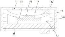
图3为本发明实施例的气动开关装置的剖面结构示意图;3 is a schematic cross-sectional structure diagram of a pneumatic switch device according to an embodiment of the present invention;
图4为本发明实施例的气动开关装置仰视面的结构示意图。FIG. 4 is a schematic structural diagram of a bottom view of a pneumatic switch device according to an embodiment of the present invention.
附图标注说明:Description of the attached drawings:
10、壳体;11、第二气孔;12、第一空间;13、第二空间;10. Shell; 11. Second air hole; 12. First space; 13. Second space;
20、电极板;21、第一气孔;20. Electrode plate; 21. First air hole;
30、第一磁吸导电组件;31、正极磁吸端子;32、负极磁吸端子;30. The first magnetically attracting conductive component; 31. The positive magnetically attracting terminal; 32. The negative magnetically attracting terminal;
40、气动形变构件;41、环状基座;42、形变部;421、插接孔;40. Pneumatic deformation member; 41. Ring-shaped base; 42. Deformation part; 421. Insertion hole;
50、第二磁吸导电组件;51、磁吸片;52、插接块;50. The second magnetically attractive conductive component; 51. The magnetic suction sheet; 52. The plug-in block;
60、气动开关装置;60. Pneumatic switch device;
70、芯片板;70. Chip board;
80、供电模块;80. Power supply module;
90、雾化模块。90. Atomization module.
具体实施方式Detailed ways
以下结合附图对本发明的具体实施方式进行详细说明。应当理解的是,此处所描述的具体实施方式仅用于说明和解释本发明,并不用于限制本发明。The specific embodiments of the present invention will be described in detail below with reference to the accompanying drawings. It should be understood that the specific embodiments described herein are only used to illustrate and explain the present invention, but not to limit the present invention.
本实施例公开一种电子烟,电子烟可以是一次性电子烟或者可重复注油使用的电子烟。电子烟包括控制系统,控制系统用以控制电子烟整体的工作过程。This embodiment discloses an electronic cigarette, which can be a disposable electronic cigarette or an electronic cigarette that can be refilled with oil. The electronic cigarette includes a control system, and the control system is used to control the overall working process of the electronic cigarette.
请结合图1,控制系统包括气动开关装置、雾化模块90、控制模块以及供电模块80。供电模块80、雾化模块90以及气动开关装置分别与控制模块导电连接。其中,控制模块可以包括芯片板70,芯片板70可以是市面上的电子烟常用的芯片板70,在此不对芯片板70的具体型号做出限定。气动开关装置可通过导线与芯片板70导电连接。Please refer to FIG. 1 , the control system includes a pneumatic switch device, an
雾化模块90可以包括雾化芯,雾化芯包括发热件,发热件可以是发热丝或陶瓷发热管或其他加热构件,发热件的导电引脚通过导线与芯片板70导电连接,或者发热件的导电引脚直接与芯片板70导电连接;电子烟油仓内的烟油通过导油棉引导至发热件上,以便由雾化芯雾化烟油。The
供电模块80用以向雾化模块90、控制模块以及气动开关装置供电;具体的,供电模块80可以包括可充电重复使用的电池,电池的两极通过导线与芯片板70连接,电池的通过芯片板70向雾化模块90以及气动开关装置供电。The
在一应用场景中,气动开关装置设在电子烟的气流流动轨迹上,用户吸用电子烟时,电子烟内产生气流流动,气流促发气动开关装置的工作状态发生变化,芯片板70根据气动开关装置的工作状态变化来控制雾化模块90开始雾化烟油或停止雾化烟油。In one application scenario, the pneumatic switch device is arranged on the airflow trajectory of the electronic cigarette. When the user inhales the electronic cigarette, an air flow is generated in the electronic cigarette, and the airflow causes the working state of the pneumatic switch device to change. The working state of the switch device is changed to control the
在现有技术中,电子烟的气动开关一般为电容式咪头,电容式咪头包括间隔且相对设置的电极板20和导电薄膜,用户吸用电子烟时,气流进入电子烟内,并且带动导电薄膜,使导电薄膜变形,这样导致导电薄膜与电极板20之间的距离发生变化,从而引起等效电容变化,电容式咪头开关将该电容变化信号反馈给电子烟的控制板,当电容变化量达到一定程度时,控制板控制电子烟的雾化器开始雾化烟油。由于导电薄膜的形变量容易受到外界因素影响,例如,温度较高时,导电薄膜容易发生形变,这样会导致电容式咪头开关的工作状态不稳定,即使较小的气流也会导致导电薄膜形变,从而导致电子烟的雾化器在电子烟不使用时容易自动启动,这现象在发热件阻值较小的情况出现概率较高,特别是0.7欧姆阻值以下的发热件,其产生的热量较大,导致电子烟内温度较高,导电薄膜更加容易发生变形。除了温度影响导电薄膜变形量以外,在电容式咪头组装过程中,其导电薄膜也容易受到触碰而发生变形,这样会导致电容式咪头在组装完成后,其导电薄膜的形状已经发生改变,这样会影响后续电容式咪头的工作灵敏度,进而影响电容式咪头工作稳定性。综上所述,现有技术的电容式咪头主要通过其导电薄膜的形变量大小来改变工作状态,由于导电薄膜的形变量容易受到外界因素干扰,这样导致电容式咪头容易出现工作状态不稳定的现象。In the prior art, the pneumatic switch of the electronic cigarette is generally a capacitive microphone head. The capacitive microphone head includes
为了解决上述问题,本实施例采用了以下方案:In order to solve the above problems, this embodiment adopts the following solutions:
请结合图1和图2,,在本实施例中,气动开关装置包括壳体10以及间隔地设于壳体10的电极板20和气动形变构件40。电极板20设有工作电路60,工作电路60包括第一磁吸导电组件30;气动形变构件40包括与电极板20相对设置且可由负压驱动而远离电极板20的形变部42;形变部42设有第二磁吸导电组件50,第二磁吸导电组件50磁吸于第一磁吸导电组件30以使工作电路60通路;借由形变部42远离电极板20的过程驱使第一磁吸导电组件30与第二磁吸导电组件50分离,从而使工作电路60断路。Referring to FIG. 1 and FIG. 2 , in this embodiment, the pneumatic switch device includes a
与现有技术相比,本实施例的形变部42只起到驱使第二磁吸导电组件50从第一磁吸导电组件30分离的作用,形变部42的形变量大小在一定范围内并不会影响气动开关装置的工作状态,即使形变部42在一定程度上发生形变,只要第二磁吸导电组件50依然磁吸于第一磁吸导电组件30,则气动开关装置的工作状态就不会改变,因而提高了气动开关装置的工作状态较为稳定。Compared with the prior art, the
在本实施例中,采用以下方案来实现负压驱动形变部42:In this embodiment, the following scheme is adopted to realize the negative pressure driving deformation part 42:
请结合图2-图4,在本实施中,壳体10为筒状结构,例如圆柱筒、棱柱筒等,气动形变构件40设于壳体10内,以将壳体10内部分隔出沿壳体10轴向排列的第一空间12和第二空间13;形变部42位于第一空间12和第二空间13之间,借由第一空间12和第二空间13的气压差形成的负压来驱使形变部42远离电极板20。具体的,在气动形变构件40的阻隔下,第一空间12和第二空间13处于空气隔离的状态,第一空间12的空气和第二空间13的空气不能够通过气动形变构件40来实现相互流通,用户在吸用电子烟时,第二空间13的部分空气被气流带出,因而第二空间13的气压相较于第一空间12的气压较低,这样即可产生负压,利用气压挤压形变部42,使形变部42朝向第二空间13移动。Referring to FIGS. 2 to 4 , in this embodiment, the
进一步的,壳体10的一端部敞开而另一端部闭合。电极板20设于壳体10敞开的端部,具体的,电极板20设于壳体10敞开的端部内,电极板20的边缘轮廓形状与壳体10敞开的端部的端口形状相适配,当电极板20设于壳体10敞开的端部内时,电极板20的周向侧壁抵接壳体10敞开的端部,从而封闭该端部,由于电极板20设于壳体10内,这样可以降低电极板20受触碰而掉落的概率,另外还可以使壳体10的外观更整洁。第一空间12位于电极板20和气动形变构件40之间,为了使第一空间12内的空气与外界空气流通,电极板20开设有两个可供空气流通的第一气孔21,当然,在其他实施例中,第一气孔21的数量可以是一个或多个。第二空间13位于壳体10闭合端部的端壁与气动形变构件40之间,为了使第二空间13与外界空气流通,壳体10闭合的端部的端壁设有第二气孔11,具体的,第二气孔11的配置数量为多个,所有第二气孔11散布在壳体10闭合的端部的端壁上。Further, one end of the
接下来对本实施例的气动形变构件40的机构作进一步阐述。Next, the mechanism of the
气动形变构件40包括环状基座41,环状基座41的形状以及尺寸均与壳体10的内部相适配,当环状基座41设于壳体10内部时,环状基座41的外周侧壁抵接壳体10内壁,优选的,环状基座41可以为硅胶座或其他弹性较好的软性材质基座,环状基座41与壳体10内部过盈配合,由于环状基座41具备一定的弹性,这样可以使环状基座41与壳体10内壁抵接较为紧密,这样一方面可以提高气密性,另一方面可以提高环状基座41较为牢固地限定在壳体10内部。形变部42为沿环状基座41径向延展且边缘连接环状基座41的形变层,具体的,形变层为硅胶膜,形变层与环状基座41一体成型,这样可以使本实施例的气动形变构件40结构较为简单,且便于制造。The
接下来对本实施例的第一磁吸导电组件30和第二磁吸导电组件50的结构以及安装方式作进一步阐述。Next, the structures and installation methods of the first magnetically attracting
在本实施例中,第一磁吸导电组件30包括可磁吸于第二磁吸导电组件50的正极磁吸端子31和负极磁吸端子32,正极磁吸端子31和负极磁吸端子32可借由第二磁吸导电组件50实现导电连接。具体的,正极磁吸端子31和负极磁吸端子32均呈为半月状,正极磁吸端子31和负极磁吸端子32对称且间隔地设在电极板20朝向形变部42的侧面上,其中,正极磁吸端子31和负极磁吸端子32均为可导电的磁铁,例如钕铁硼磁铁、钐钴磁铁、铝镍钴磁铁、铁铬钴磁铁等。在其他实施例中,正极磁吸端子31可以由磁铁和一导电件组成,磁铁用以磁吸第二磁吸导电组件50,导电件用以与第二磁吸导电组件50抵接且导电连接,负极磁吸端子32的结构亦如此,当然,在另一实施例中,正极磁吸端子31和负极磁吸端子32的两者之一设置有磁铁来磁吸第二磁吸导电组件50即可。In this embodiment, the first magnetically attractive
进一步的,在本实施例中,正极磁吸端子31和负极磁吸端子32均与电极板20上的工作电路60导电连接,当正极磁吸端子31和负极磁吸端子32磁吸于第二磁吸导电组件50时,工作电路60通路,当正极磁吸端子31和负极磁吸端子32与第二磁吸导电组件50分离时,工作电路60断路。工作电路60通过导线与控制模块的芯片板70导电连接,当工作电路60通路时,工作电路60有电流通过,并且芯片板70收到到工作电路60有电流通过的对应信号,这时,芯片板70停止向雾化芯的发热件输送电流,这样即可使发热件停止加热,此时电子烟处于停止工作状态。当吸用电子烟时,流经电子烟内部的气流使第一空间12和第二空间13之间的存在气压差,从而通过负压驱动形变部42远离电极板20,形变部42带动第二磁吸导电组件50从正极磁吸端子31和负极磁吸端子32上分离,这时,工作电路60断路,工作电路60没有电流通过,这时,控制模块的芯片板70收到工作电路60没有电流通过的对应信号,芯片板70控制发热件开始加热烟油。Further, in this embodiment, the positive
在前述方案中,由于正极磁吸端子31和负极磁吸端子32均采用磁吸的方式来与第二磁吸导电组件50连接,因而,其连接牢固程度较为可靠,在不使用电子烟时,外界的气流难以带动形变部42,从而防止形变部42带动第二磁吸导电组件50从正极磁吸端子31和负极磁吸端子32上分离,依此方式来提高气动开关装置的工作状态稳定性,进而降低出现电子烟在不使用时其加热件自动加热烟油现象的概率。In the aforementioned solution, since both the positive
接下来对本实施例的第二磁吸导电组件50的结构以及安装方式作进一步阐述。Next, the structure and installation method of the second magnetically attractive and
在本实施例中,第二磁吸导电组件50包括可导电的磁吸片51,磁吸片51为可导电的磁铁,例如钕铁硼磁铁、钐钴磁铁、铝镍钴磁铁、铁铬钴磁铁等;磁吸片51的背面凸伸出一插接块52;形变层设有插接孔421,优选的,插接孔421设于形变层的中间部位;插接块52自形变层朝向电极板20的一侧插设于插接孔421,依此方式将磁吸片51来装配在形变层上,装配过程简单快捷。其中,由于磁吸片51的重力以及其与第一磁吸导电组件30的磁吸力拉扯形变层,这样会使形变层产生一定的形变,因而,形变层呈现出如图中所示的凹陷状。In this embodiment, the second magnetic attraction and
在其他实施例中,插接块52呈沿磁吸片51轴向延伸的柱状结构,例如圆柱结构、棱柱结构等,插接块52的侧壁开设有环绕插接块52轴线的环形槽;形变层开设有可供插接块52插设的插接孔421;在插接块52插设于插接孔421时,插接孔421的边缘位于环形槽内,在环形槽的限位下,插接块52不会轻易脱离插接孔421,从而提高了磁吸片51与形变层的连接可靠性。In other embodiments, the plug-in
只要不违背本发明创造的思想,对本发明的各种不同实施例进行任意组合,均应当视为本发明公开的内容;在本发明的技术构思范围内,对技术方案进行多种简单的变型及不同实施例进行的不违背本发明创造的思想的任意组合,均应在本发明的保护范围之内。Any combination of various embodiments of the present invention shall be regarded as the contents disclosed in the present invention as long as it does not violate the idea of the present invention; within the scope of the technical concept of the present invention, various simple modifications and Any combination of different embodiments that do not violate the idea of the present invention should fall within the protection scope of the present invention.
Claims (10)
Priority Applications (1)
| Application Number | Priority Date | Filing Date | Title |
|---|---|---|---|
| CN202210542866.XA CN114732162B (en) | 2022-05-18 | 2022-05-18 | Pneumatic switch device, control system and electronic cigarette |
Applications Claiming Priority (1)
| Application Number | Priority Date | Filing Date | Title |
|---|---|---|---|
| CN202210542866.XA CN114732162B (en) | 2022-05-18 | 2022-05-18 | Pneumatic switch device, control system and electronic cigarette |
Publications (2)
| Publication Number | Publication Date |
|---|---|
| CN114732162A true CN114732162A (en) | 2022-07-12 |
| CN114732162B CN114732162B (en) | 2025-05-30 |
Family
ID=82287658
Family Applications (1)
| Application Number | Title | Priority Date | Filing Date |
|---|---|---|---|
| CN202210542866.XA Active CN114732162B (en) | 2022-05-18 | 2022-05-18 | Pneumatic switch device, control system and electronic cigarette |
Country Status (1)
| Country | Link |
|---|---|
| CN (1) | CN114732162B (en) |
Cited By (1)
| Publication number | Priority date | Publication date | Assignee | Title |
|---|---|---|---|---|
| CN119908528A (en) * | 2025-04-01 | 2025-05-02 | 深圳市东一思创电子有限公司 | Pneumatic magnetic sensor device and electronic atomizer based on anti-false touch |
Citations (8)
| Publication number | Priority date | Publication date | Assignee | Title |
|---|---|---|---|---|
| CN203760374U (en) * | 2013-12-04 | 2014-08-06 | 佛山市顺德区奇林电气有限公司 | Novel magnetic conductive pressure switch |
| CN203799956U (en) * | 2014-03-21 | 2014-08-27 | 昂纳自动化技术(深圳)有限公司 | Capacitive pneumatic switch |
| CN106153127A (en) * | 2015-03-30 | 2016-11-23 | 纳米新能源(唐山)有限责任公司 | Electronic cigarette pneumatic transmitter, airflow treatment device and electronic cigarette |
| CN209185758U (en) * | 2018-10-19 | 2019-08-02 | 歌尔科技有限公司 | Airflow sensor switch, vaporizer and electronic cigarette |
| CN111602850A (en) * | 2019-05-31 | 2020-09-01 | 钟术光 | Aerosol generating or aerosolization system or electronic cigarette and device thereof |
| CN111602858A (en) * | 2019-05-16 | 2020-09-01 | 深圳市艾维普思科技有限公司 | Pneumatic switch of electronic cigarette, power supply device of electronic cigarette and electronic cigarette |
| CN214677586U (en) * | 2021-03-31 | 2021-11-12 | 深圳市克莱鹏科技有限公司 | Electronic cigarette with integrated electromagnetic induction switch |
| WO2021240136A1 (en) * | 2020-05-29 | 2021-12-02 | Nicoventures Trading Limited | Aerosol provision systems |
-
2022
- 2022-05-18 CN CN202210542866.XA patent/CN114732162B/en active Active
Patent Citations (8)
| Publication number | Priority date | Publication date | Assignee | Title |
|---|---|---|---|---|
| CN203760374U (en) * | 2013-12-04 | 2014-08-06 | 佛山市顺德区奇林电气有限公司 | Novel magnetic conductive pressure switch |
| CN203799956U (en) * | 2014-03-21 | 2014-08-27 | 昂纳自动化技术(深圳)有限公司 | Capacitive pneumatic switch |
| CN106153127A (en) * | 2015-03-30 | 2016-11-23 | 纳米新能源(唐山)有限责任公司 | Electronic cigarette pneumatic transmitter, airflow treatment device and electronic cigarette |
| CN209185758U (en) * | 2018-10-19 | 2019-08-02 | 歌尔科技有限公司 | Airflow sensor switch, vaporizer and electronic cigarette |
| CN111602858A (en) * | 2019-05-16 | 2020-09-01 | 深圳市艾维普思科技有限公司 | Pneumatic switch of electronic cigarette, power supply device of electronic cigarette and electronic cigarette |
| CN111602850A (en) * | 2019-05-31 | 2020-09-01 | 钟术光 | Aerosol generating or aerosolization system or electronic cigarette and device thereof |
| WO2021240136A1 (en) * | 2020-05-29 | 2021-12-02 | Nicoventures Trading Limited | Aerosol provision systems |
| CN214677586U (en) * | 2021-03-31 | 2021-11-12 | 深圳市克莱鹏科技有限公司 | Electronic cigarette with integrated electromagnetic induction switch |
Cited By (2)
| Publication number | Priority date | Publication date | Assignee | Title |
|---|---|---|---|---|
| CN119908528A (en) * | 2025-04-01 | 2025-05-02 | 深圳市东一思创电子有限公司 | Pneumatic magnetic sensor device and electronic atomizer based on anti-false touch |
| CN119908528B (en) * | 2025-04-01 | 2025-06-06 | 深圳市东一思创电子有限公司 | Pneumatic magnetic sensing device based on anti-false touch and electronic atomizer |
Also Published As
| Publication number | Publication date |
|---|---|
| CN114732162B (en) | 2025-05-30 |
Similar Documents
| Publication | Publication Date | Title |
|---|---|---|
| CN209546930U (en) | Atomizing head, atomizer and electronic cigarette | |
| JP2015500647A (en) | Rechargeable electronic cigarette | |
| CN207969654U (en) | Electronic cigarette and its atomizer | |
| CN113768196A (en) | Electronic atomization device and heating assembly thereof | |
| CN215603176U (en) | Electronic atomization device, battery assembly and atomizer | |
| CN114732162A (en) | Pneumatic switching devices, control systems and electronic cigarettes | |
| EP3892137A1 (en) | Electronic cigarette and atomizing device therefor | |
| EP4079174A1 (en) | Electronic cigarette | |
| CN213756678U (en) | Atomizer | |
| CN112021661A (en) | Magnetic induction switch structure applied to induction starting during smoking of electronic cigarette | |
| CN113907433A (en) | Atomizer and aerosol generating device | |
| CN213215337U (en) | Electronic cigarette | |
| CN110693089B (en) | Electronic cigarette components and electronic cigarettes | |
| CN220423122U (en) | Atomizer and electronic atomization device | |
| CN112914165A (en) | Split type electromagnetic induction switch device for electronic cigarette and electronic cigarette | |
| CN109998176B (en) | Electronic cigarette and electronic cigarette set with side disassembly and assembly of cigarette cartridge | |
| CN219741877U (en) | Atomizer capable of reducing self-starting of airflow sensor | |
| CN217906340U (en) | Atomizer, tobacco rod and electronic cigarette | |
| CN216796486U (en) | Atomizer and aerosol generating device | |
| CN212117063U (en) | Connection structure and aerosol-generating device | |
| CN214677585U (en) | Split type electromagnetic induction switch device for electronic cigarette and electronic cigarette | |
| CN207784275U (en) | Electronic cigarette | |
| CN211379631U (en) | Electronic cigarette | |
| CN218551332U (en) | Ceramic electrode, atomizer and electronic atomization device | |
| CN220607338U (en) | Electronic cigarette |
Legal Events
| Date | Code | Title | Description |
|---|---|---|---|
| PB01 | Publication | ||
| PB01 | Publication | ||
| SE01 | Entry into force of request for substantive examination | ||
| SE01 | Entry into force of request for substantive examination | ||
| GR01 | Patent grant | ||
| GR01 | Patent grant | ||
| TR01 | Transfer of patent right | ||
| TR01 | Transfer of patent right |
Effective date of registration: 20250909 Address after: 523000 Room 201, building 1, No. 5, Xiaonan industrial Second Road, Humen Town, Dongguan City, Guangdong Province Patentee after: Houshan Electronics (Dongguan) Co.,Ltd. Country or region after: China Address before: No.98 Chaodong Road, Chashan Town, Dongguan City, Guangdong Province 523000 Patentee before: Dongguan Changhan Technology Co.,Ltd. Country or region before: China |