Disclosure of Invention
It is an object of the present invention to eliminate the above-mentioned disadvantages of the hitherto known powder inhalers and to provide a powder inhaler with improved electronic detection of the drug administration.
In particular, it is an object of the present invention to provide a powder inhaler assembly provided with an electronic module capable of detecting movements of mechanical parts of the powder inhaler in order to infer drug administration in a safe and reliable manner.
It is also an object of the present invention to provide an electronic module capable of reading the movements of such mechanical parts of a powder inhaler without the need for the related structural modifications of existing powder inhalers, such as those disclosed in WO 2004/012801 or WO2016/000983 of the same applicant.
At least one of the above objects is substantially achieved by an assembly, an electronic module and a powder inhaler according to the appended claims and/or one or more of the following aspects.
Aspects of the invention are disclosed below.
According to a first independent aspect, a powder inhaler assembly comprises:
a powder inhaler, comprising:
a container for storing a powdered medicament;
a suction nozzle and a suction channel connected to the suction nozzle;
a metering device having a dosing recess; wherein the metering device is movable relative to the container and the inhalation channel between an idle state in which the dosing recess is in communication with the opening of the container for filling with a dose of powdered medicament and a triggered state in which the dosing recess is in communication with the inhalation channel for enabling inhalation of the dose of powdered medicament contained in the dosing recess through the mouthpiece.
The powder inhaler assembly further comprises:
an electronic module attached or attachable to the powder inhaler and comprising:
a non-contact sensor, optionally an optical proximity sensor, is positioned and configured to sense a position of at least a portion of the metering device, thereby at least detecting when the metering device is in a triggered state.
In a second independent aspect, an electronic module is attached or attachable to a powder inhaler. The powder inhaler includes:
a container for storing a powdered medicament;
a suction nozzle and a suction channel connected to the suction nozzle;
a metering device having a dosing recess; wherein the metering device is movable relative to the container and the inhalation channel between an idle state in which the dosing recess is in communication with the opening of the container for filling with a dose of powdered medicament and an activated state in which the dosing recess is in communication with the inhalation channel for enabling inhalation of the dose of powdered medicament contained in the dosing recess through the mouthpiece.
The electronic module includes:
a non-contact sensor positioned and configured to sense a position of at least a portion of the metering device, thereby at least detecting when the metering device is in a triggered state; wherein the non-contact sensor is an optical proximity sensor.
In a third independent aspect, a powder inhaler comprises:
a container for storing a powdered medicament;
a suction nozzle and a suction channel connected to the suction nozzle;
a metering device having a dosing recess; wherein the metering device is movable relative to the container and the inhalation channel between an idle state in which the dosing recess is in communication with the opening of the container for filling with a dose of powdered medicament and a triggered state in which the dosing recess is in communication with the inhalation channel for enabling inhalation of the dose of powdered medicament contained in the dosing recess through the mouthpiece;
a housing having a corresponding window; wherein the metering device and optionally the container and the suction channel are accommodated in the housing; wherein the metering device is at least partially visible through the window;
wherein the powder inhaler is configured to be attached to an electronic module comprising an optical proximity sensor;
wherein, when the electronic module is attached to the powder inhaler, the window of the housing faces the window of the housing of the electronic module such that the optical proximity sensor faces at least a portion of the metering device to sense a position of the at least a portion of the metering device to at least detect when the metering device is in a triggered state.
The applicant has verified that the present invention allows to deduce that a dose of medicament is dispensed in a safe and reliable manner by reading the configuration, position and actuation of the mechanical metering device of the powder inhaler by a non-contact sensor. The powder inhaler incorporates a breath-actuated mechanism that is triggered when the inspiratory flow exceeds the minimum level required to move the balance of the mechanism, thereby releasing the metered dose from the dosing recess. The actuation is achieved by releasing the spring member (i.e. the coupling member) which will then move the transparent plastic part (called dose protector) forward, thereby exposing the formulation to the inhalation channel within the mouthpiece. The attached electronics module is configured to detect at least a portion of such triggering of the mechanism, thereby inferring release of the metered dose.
The applicant has verified that the present invention allows such tests to be carried out without relevant structural modifications to existing powder inhalers, such as those disclosed in WO 2004/012801 or WO 2016/000983. In fact, there is no direct access to the internal volume of the powder inhaler.
In one aspect, the electronic module is removably attached to the powder inhaler, optionally by a clip-on coupling. Coupling and decoupling are both simple and fast.
In one aspect, the electronic module, once separated from the powder inhaler, can be reused with another powder inhaler. Once the medication in the old inhaler is exhausted, the same electronic module can be used with another new powder inhaler.
In one aspect, the container is filled or configured to be filled with an amount of powder medicament corresponding to a plurality of doses (optionally 100-200 doses).
In one aspect, the non-contact sensor is a proximity sensor. A proximity sensor is a sensor that can detect the presence of a nearby object without any physical contact. Proximity sensors emit an electromagnetic field or beam of electromagnetic radiation and look for changes in the field or return signal. Examples of proximity sensors are capacitive sensors, inductive sensors, optical or photoelectric sensors.
In one aspect, the proximity sensor is an optical proximity sensor.
In one aspect, the optical proximity sensor operates in the near infrared spectrum.
In one aspect, an optical proximity sensor detects changes in reflected electromagnetic waves (optionally light) due to movement of at least a portion of a metrology device.
In one aspect, the powder inhaler comprises a housing, optionally a plastic housing, and the electronic module comprises a housing, optionally a plastic housing.
In one aspect, the housing is removably attachable to the shell, optionally by clipping the shell to the shell or clipping the shell to the shell.
In one aspect, the container, the inhalation passage and the metering device are housed in a housing.
In one aspect, the housing has a corresponding window and the shell has a corresponding window.
In one aspect, when the electronic module is attached to the powder inhaler, the window of the housing faces the window of the housing such that the optical proximity sensor faces at least a portion of the metering device.
In one aspect, an optical proximity sensor is placed in the housing.
In one aspect, the window of the housing and the window of the case are optically transparent windows. The window is transparent in the relevant electromagnetic spectrum for the optical proximity sensor.
There are no relevant modifications to existing inhalers (e.g. those disclosed in WO 2004/012801 or WO 2016/000983) other than the small optically transparent window forming part of the inhaler housing. This window is positioned directly below the portion of the mechanism that is triggered by the inhalation of the user.
In one aspect, an optical proximity sensor includes an emitter that emits light, optionally in the near infrared spectrum, and an optical receiver having a photosensitive portion; wherein the output signal of the optical receiver is dependent on the electromagnetic wave, optionally light, reflected by the at least part of the metrology device.
In one aspect, the emitter is an LED (light emitting diode) or VCSEL (vertical cavity surface emitting laser).
In one aspect, the electronic module comprises an electronic control unit, optionally a microprocessor, operatively connected to the non-contact sensor.
In one aspect, an optical proximity sensor or electronic control unit includes a lock-in amplifier configured to remove optical noise, in particular to remove contributions from external light.
In one aspect, the shape and/or size of the window of the housing and/or the window of the case is configured to change the field of view (optical mask) of the optical proximity sensor in order to improve the position of the at least a portion of the detection metrology device.
In one aspect, a pinhole sensor cover is interposed between the optical proximity sensor and the at least a portion of the metrology device to change a field of view (optical mask) of the optical proximity sensor to improve detecting a position of the at least a portion of the metrology device.
In one aspect, at least one lens is interposed between the optical proximity sensor and the at least a portion of the metrology device to better redirect and/or re-image the emitted and/or reflected light.
In one aspect, the pinhole sensor cover and/or the at least one lens are part of the electronic module and/or the powder inhaler.
In one aspect, an electronic module includes a Printed Circuit Board (PCB).
In one aspect, an electronic module includes a memory.
In one aspect, the electronic module comprises a communication interface, optionally a wireless communication interface, optionally a bluetooth communication interface.
In one aspect, the communication interface is configured to connect the electronic module to an external device, such as a computer, smartphone, tablet, or the like. All the operating parameters and data of the powder inhaler detected by the electronic module can be transmitted to the external device.
In one aspect, the electronic module includes at least a battery to power the contactless sensor, the electronic control unit, and the communication interface.
In one aspect, the contactless sensor, the electronic control unit, the communication interface, the memory, and the battery are mounted on a printed circuit board.
In one aspect, the electronic control unit is disposed in the housing.
In one aspect, an electronic control unit is configured to perform tasks including at least the following:
-reading the output signal from the contactless sensor at regular intervals;
-optionally filtering and optionally normalizing the output;
-comparing the output with a threshold value and discriminating whether the metering device is in a triggered state.
In one aspect, reading the output signals from the non-contact sensors is performed at a rate greater than 10Hz, optionally greater than 100Hz, optionally 25Hz (with regular intervals less than 100ms, optionally less than 10ms, optionally 40 ms).
In one aspect, the optical assembly of the optical proximity sensor is only active for a fraction of a millisecond (optionally between 100-.
In one aspect, a signal processing algorithm is implemented within the electronic control unit to filter the output.
In one aspect, the signal processing is performed at least in part by a non-contact sensor.
In one aspect, optionally filtering the output by a signal processing algorithm comprises:
-running a median filter on the plurality of samples, wherein the median filter output selects elements after sorting the samples in ascending order;
-subtracting the previous median filter output from the current median filter output.
In one aspect, a metrology apparatus comprises: a shuttle having a dosing recess. In one aspect, the shuttle is movable between a filling position corresponding to an idle state of the metering device, in which the dosing recess is aligned with the opening of the container for filling the dose of powdered medicament, and an inhalation position corresponding at least to a triggered state of the metering device, in which the dosing recess is aligned with the inhalation passage.
In one aspect, the shuttle is slidably movable between a fill position and a suction position.
In one aspect, a metrology apparatus comprises: a protective member provided between the shuttle and the suction passage.
In one aspect, the protection member is movable between a closed position in which the protection member covers the administration groove of the shuttle when the shuttle is in the inhalation position, thereby preventing the powdered medicine contained in the administration groove from entering the inhalation channel, and an open position in which the protection member does not cover the administration groove, thereby exposing the administration groove to the inhalation channel, thereby enabling inhalation of the dose of powdered medicine contained in the administration groove.
In one aspect, the protective member is disposed on a shuttle that is slidably movable between a closed position and an open position.
In one aspect, the non-contact sensor is positioned and configured to sense at least a position of the shuttle and/or the protective member.
In one aspect, in the triggered state, the shuttle is in the intake position and the protective member is in the open position.
In one aspect, the metering device is movable to a standby state with respect to the container and the suction channel, wherein the shuttle is in the suction position and the protective member is in the closed position.
In one aspect, the contactless sensor is positioned and configured to sense a transition between a standby state and a trigger state.
In one aspect, the powder inhaler comprises an inhalation or breath actuated mechanism coupled to the protective member such that if the protective member is in the closed position, the inhalation actuated mechanism moves the protective member to the open position if the inhalation suction created by the user exceeds a predetermined value.
In one aspect, the inhalation-actuated mechanism comprises an inhalation-actuated member, optionally a flap, movable between a first position and a second position; the suction-actuating member is coupled to the protective member such that if the suction force exceeds a predetermined value, the suction-actuating member moves from the first position to the second position, thereby moving the protective member from the closed position to the open position.
In one aspect, the non-contact sensor is positioned and configured to sense a position of at least a portion of the inhalation-actuated mechanism.
In one aspect, an optical proximity sensor detects changes in reflected electromagnetic waves (optionally light) due to movement of at least a portion of a suction actuated mechanism.
In one aspect, the inhalation-actuated mechanism includes a coupling member that couples the inhalation-actuated member to the protective member.
In one aspect, the inhalation-actuated mechanism comprises at least one resilient element, optionally arranged on the coupling member.
In one aspect, the resilient element is arranged such that when the lid is closed and the shuttle is in the filling position, the resilient element retains the suction actuated member in its first position.
In one aspect, when the shuttle is pushed forward to the suction position by opening the cap, the resilient element releases the suction-activated member to allow the suction-activated member to move from its first position to its second position due to the suction force exceeding a predetermined value.
In one aspect, the coupling member includes an extension that engages an opening formed in the protective member.
In one aspect, the extension of the coupling member is movably arranged in a longitudinal opening formed in the shuttle along a longitudinal direction of the shuttle such that the extension of the coupling member is freely movable in the longitudinal opening of the shuttle from its initial position to its end position, while movement of the shuttle from the suction position to the filling position causes the extension of the coupling member to abut against an edge of the longitudinal opening, thereby moving the coupling member back to its initial position.
In one aspect, the non-contact sensor is positioned and configured to sense a position of at least a portion of the coupling member (optionally an extension of the coupling member).
In one aspect, the non-contact sensor is positioned and configured to sense a position of at least a portion of the metering device and/or at least a portion of the suction actuated mechanism.
In one aspect, the optical proximity sensor detects a change in the reflected electromagnetic wave (optionally light) due to movement of the shuttle and/or the protective member and/or the coupling member (optionally an extension of the coupling member).
In one aspect, the protective member has a surface that reflects light in a specular manner, and the shuttle has a surface that diffusely reflects light.
In one aspect, the coupling member has a surface that diffusely reflects light.
In one aspect, the protective member has a smooth surface finish that reflects light in a specular manner (specular reflection), while the other two components (shuttle and coupling member) reflect light more in a diffuse manner (also referred to as diffuse reflection).
In one aspect, the shuttle and/or the protective member and/or the coupling member have at least one marker detectable by the optical proximity sensor.
In one aspect, the marking is part of or an accessory coupled to the shuttle and/or the protection member and/or the coupling member.
In one aspect, the indicia is diffusely reflective or specularly reflective.
In one aspect, the indicia is diffusely reflective indicia disposed on a specularly reflective surface (e.g., a surface of a protective member or shuttle).
In one aspect, the indicia are specular reflective indicia placed on a diffuse reflective surface (e.g., a surface of the coupling member).
In one aspect, the non-contact sensor senses a transition in the trigger state when the light is primarily reflected by the protective member.
In one aspect, the output signal of the optical receiver reaches a maximum value when the light is mainly reflected by the protective member.
In one aspect, the protective member faces the non-contact sensor when the protective member is in the open position.
In one aspect, the total light received by the optical proximity sensor is dominated by the combination of light reflected from all three parts (the guard member, the coupling member and the shuttle) and will be at its maximum when the primary reflection source is a dose protector. This occurs when the inhalation-actuated mechanism of the powder inhaler is triggered due to the positioning of the optical proximity sensor.
In one aspect, a powder inhaler includes a housing and a cover rotatably coupled to the housing.
In one aspect, the electronic module is attached or attachable to a portion of the powder inhaler opposite the cover.
In one aspect, the cover is movable between its closed position covering the mouthpiece and its open position exposing the mouthpiece.
In one aspect, the electronic module includes a lid opening switch.
In one aspect, the lid opening switch is operatively connected to the electronic control unit.
In one aspect, opening of the lid beyond a range of rotational movement of the lid from the closed position of the lid causes the shuttle to move from the fill position to the suction position.
In one aspect, opening of the lid beyond a range of rotational movement of the lid from the closed position of the lid triggers a lid open switch, which causes activation of the non-contact sensor.
In one aspect, the range of rotational movement is approximately 80 degrees.
In one aspect, closing the cap moves the shuttle from the suction position to the fill position.
In one aspect, closing the lid releases the lid-opening switch, which causes deactivation of the non-contact sensor.
In one aspect, the non-contact sensor (and detection of the state of the metering device) is only active when the cover is opened beyond the range of rotational movement.
In one aspect, the lid opening switch comprises a mechanical detector switch and a spring-loaded mechanical part, optionally shaped as an arm.
In one aspect, the spring-loaded mechanical part is movable between a rest position in which it does not activate the mechanical detector switch when the lid is in the closed position and an operative position in which it depresses the mechanical detector switch when the lid is in the open position.
In one aspect, the spring is configured to move the spring-loaded mechanical part toward the rest position when the lid is in the closed position.
In one aspect, the electronic module includes an attachment detection switch that interacts with the powder inhaler when the electronic module is attached to the powder inhaler.
In one aspect, the attachment detection switch is a mechanical detection switch.
In one aspect, the attachment detection switch is operatively connected to the electronic control unit.
In one aspect, attaching the electronic module to the powder inhaler triggers an attachment detection switch, which causes activation of a lid opening switch.
In one aspect, detaching the electronic module from the powder inhaler releases the attachment detection switch, which causes deactivation of the lid opening switch.
In one aspect, the closed or open state of the cover is monitored only when the electronic module is attached.
In one aspect, the electronic module uses two mechanical switches to determine a) when it is attached to the inhaler, and b) when the cover of the inhaler is open and thus actuation of the internal mechanism can occur.
In one aspect, the electronic module is configured to distinguish between three states:
an idle state, in which the electronic module is attached to the powder inhaler, the attachment detection switch is triggered, the lid is closed and the lid opening switch is released and no inhalation takes place,
a standby state in which the lid is open, the lid opening switch is triggered and the metering device can be triggered,
-a triggered state, in which the inhalation flow has released the protective member and a metered dose can be dispensed.
In one aspect, the electronic control unit is configured to store in the memory and/or to send data related to an event of the powder inhaler, such as triggering of the metering device and/or attachment/detachment of the electronic module to/from the powder inhaler and/or opening/closing of the lid, to the external device via the communication interface.
In one aspect, the electronic control unit is configured to first store the data in the memory and then transmit the data to the external device after a time delay.
In one aspect, the electronic control unit is configured to transmit the data to an external device on demand. The data can only be stored in the electronic control unit as long as a connection to an external device is not available. Therefore, the electronic control unit can work normally and save data without external equipment.
Detailed Description
Referring to the drawings, fig. 1 and 2 show a powder inhaler assembly 1 according to the present invention. The powder inhaler assembly 1 comprises a powder inhaler 2 and an electronic module 3. The powder inhaler 2 may be substantially identical to the powder inhaler disclosed in document WO 2004/012801 or document WO2016/000983 of the same applicant. Therefore, only the main part and the difference from WO 2004/012801 or WO2016/000983 will be described in detail in the following description.
Powder inhaler
The powder inhaler 2 shown in fig. 1 comprises a housing 4 and a cover 5 pivotably or rotatably coupled to the housing 4. As can be seen from fig. 2, the lid 5 can be opened to expose the mouthpiece 6, through which the user can inhale the powdered medicament through the mouthpiece 6. At the upper front side of the mouthpiece 6, a slot 7 allowing air to enter is formed in the housing 4.
The powder inhaler 2 comprises a container 8 for storing a powdered medicament, an inhalation channel 9 connected to the mouthpiece 6 and a metering device 10. The suction channel 9 has a first opening connected to the suction nozzle and a second opening opposite to the first opening. As shown in fig. 5, 7 and 9, all of these elements are housed within the housing 4.
The container 8 is filled or configured to be filled with an amount of powder medicament corresponding to a plurality of doses (e.g. up to 100-.
The metering device 10 is movable relative to the container 8 and relative to the inhalation channel 9 between an idle state, in which the dosing recess 11 communicates with the opening 12 of the container 8 for filling with a dose of powdered medicament, and an activated state, in which the dosing recess 11 communicates with the inhalation channel 9 to enable inhalation of the dose of powdered medicament contained in the dosing recess 11 through the mouthpiece 6.
The metering device 10 comprises a shuttle 13, the shuttle 13 having a dosing recess 11 formed on an upper surface thereof like a cup-shaped recess. The shuttle 13 is slidably movable between a fill position (fig. 5) and a suction position (fig. 7 and 9). The filling position corresponds to an idle state of the metering device 10 (fig. 5), in which the dosing recess is aligned with the opening 12 of the container 8 in order to be filled with the dose of powdered medicament. The inhalation position corresponds to an armed state (fig. 7) and a triggered state (fig. 9) of the metering device 10, which will be described in detail later, in which the dosing recess 11 is aligned with the inhalation channel 9.
The shuttle 13 is mechanically coupled to the lid 5 such that opening of the lid 5 moves the shuttle 13 from the filling position to the suction position beyond the range of rotational movement of the lid from its closed position. Closure of the cap 5 causes the shuttle 13 to move from the suction position back to the filling position. Fig. 5 shows the cover 5 in the closed position and the shuttle 13 in the filling position. Fig. 7 and 9 show the cover 5 in the open position and the shuttle 13 in the suction position. For example, the range of rotational movement that causes the shuttle to slide from the fill position to the suction position is eighty degrees.
The metering device 10 further comprises a protective member 14 provided between the shuttle 13 and the suction channel 9. The protective member 14 is a transparent or translucent plate disposed between the second opening of the suction passage 9 and the shuttle 13. The protective member 14 has a smooth surface finish that reflects light in a specular manner (mirror-like reflection).
The protective member 14 is parallel with respect to the shuttle 13 and is slidably movable on the shuttle 13 between a closed position and an open position. In the closed position, the protective member 14 is moved back towards the second opening of the suction channel 9 and towards the container 8. In the closed position, the rear part of the protective member 14 may at least partially close the second opening of the suction channel 9. In the open position, the protective member 14 is moved forward towards the wall of the housing 4. In the open position, the rear part of the protective member 14 keeps the second opening of the suction channel 9 open.
When the shuttle 13 is in the filling position, the protective member 14 is in the closed position. When the shuttle 13 is in the suction position, the protective member 14 is movable between a closed position and an open position. Thus, the metering device 10 is configured to adopt the three different states described above (idle, standby, triggered), and these states are determined by the positions of the shuttle 13 and the protective member 14, as disclosed in table 1 below.
TABLE 1
| Status of a metering device
|
Position of shuttle
|
Position of the protective member
|
Drawing (A)
|
| Free up
|
Filling in
|
Closure is provided
|
5 and 6
|
| Ready for use
|
Inhalation
|
Closure is provided
|
7 and 8
|
| Triggering
|
Inhalation
| Open | |
|
9 and 10 |
In the idle state of fig. 5 and 6, the shuttle 13 is in the filling position and the protection member 14 is in the closed position. The protective member 14 does not cover the dosing recess 11. The dosing recess 11 communicates with an opening 12 of the container 8 for receiving a dose of medicament.
In the standby state of fig. 7 and 8, the shuttle 13 is in the suction position and the protective member 14 is in the closed position. The protective member 14 covers the administration recess 11. The protection member 14 prevents the powdered medicine contained in the administration groove 11 from entering the inhalation channel 9 and from being lost in case of rotation or movement of the inhaler in an inclined position before inhalation manipulation or if the user blows air to the mouthpiece.
In the trigger state of fig. 9 and 10, the shuttle 13 is in the suction position and the protective member 14 is in the open position. The protection member 14 does not cover the administration recess 11 so that the administration recess 11 is exposed to the inhalation passage 9, thereby enabling the user to inhale the dose of powdered medicine contained in the administration recess 11.
The powder inhaler 2 comprises a breath or inhalation actuated mechanism 15 coupled to the protective member 14. The suction-activated mechanism 15 comprises a suction-activated member 16 shaped like a flap, a coupling member 17 and an elastic element 18 arranged on the coupling member 17 (see fig. 11, 12 and 13). Another elastic element, not shown in the drawings, may be mounted on the coupling member 17 on the opposite side with respect to the elastic element 18 (as in WO 2016/000983). The flap 16 is coupled to the protective member 14 by a coupling member 17 such that if there is a suction attraction force exceeding a predetermined value, the flap 16 moves from the first position to the second position, thereby moving the protective member 14 from the closed position to the open position. The tabs 16 are placed within the housing 4 adjacent the slots 7. In the first position (fig. 5), the vanes 16 separate the slot 7 from the suction channel 9 and are located in the main airflow path. The flap 16 provides resistance if the user blows into the device and gives positive feedback. In the second position (fig. 9), the flap 16 is rotated relative to the first position to open the slot 7 and allow air to flow through the slot 7 into the suction channel 9 and out of the suction nozzle 6.
The elastic element 18 is arranged such that said elastic element 18 holds the flap 16 in its first position. When the shuttle 13 is pushed forward by opening the cap 5, the resilient element 18 is compressed and loaded and the reset force exerted on the flap 16 is released, so that if there is a sufficiently high suction force in the suction channel 9, the flap 16 can pivot or rotate from a first position to a second position, the second position pivoting downwards with respect to the first position. The other elastic element applies a suitable force to the coupling member 17 which is released during inhalation. The downward movement of the flap 16 during inhalation releases part of the force exerted by the further resilient element on the coupling member 17, while the closing of the lid 5 tensions the further resilient element.
With reference to fig. 11 to 13, the flaps 16 are hinged to the casing 4 so as to rotate between a first position and a second position about respective rotation axes X-X substantially perpendicular to the main axis Z-Z of the suction channel 9 (fig. 5, 7 and 9). The coupling member 17 is also hinged to the casing 4 so as to rotate between respective first and second positions about respective rotation axes Y-Y substantially perpendicular to the main axis Z-Z of the suction channel 9 and parallel to the rotation axis X-X.
The coupling member 17 comprises an arm 19 projecting towards the tab 16 and engaging with the tab 16 such that (with reference to figures 5, 7, 9, 11, 12 and 13) a counterclockwise rotation of the tab 16 from the first position to the second position causes a clockwise rotation of the coupling member 17 from its respective first position towards its respective second position.
The coupling member 17 comprises an extension 20 engaging an opening 21 formed in the protection member 14 in order to move the protection member 14 from the closed position to the open position and vice versa when the coupling member 17 is moved from its respective first position to its respective second position.
The extension 20 of the coupling member 17 is also movably arranged in a longitudinal opening 22, which longitudinal opening 22 is formed in the shuttle 13 in the longitudinal direction of the shuttle 13, such that said extension 20 can move freely in the longitudinal opening 22, while the movement of the shuttle 13 from the suction position to the filling position causes the extension 20 of the coupling member 17 to abut against the edge of the longitudinal opening 22, thereby moving the coupling member 20 back to its initial first position.
The housing 4 has an optically transparent window 23 positioned adjacent the metering device 10 such that the metering device 10 is at least partially visible from outside the housing 4 through the window 23. In particular, the shuttle 13, the protective member 14 and the distal end of the extension 20 are visible through the window 23. The protective member 14 has a smooth surface finish that reflects light in a specular manner (mirror-like reflection), while the shuttle 13 and the extension portion 20 reflect light more in a diffuse reflection manner (diffuse reflection). All the components of the powder inhaler 2 may be made of a plastic material.
Electronic module
The electronic module 3 is configured to be removably attached to the powder inhaler 2 such that once the old inhaler runs out of medicament, the same electronic module 3 can be used with another new powder inhaler 2. In the embodiment shown in the figures, the electronic module 3 is attached or attachable to a portion of the powder inhaler 2 opposite the cover 5.
The electronic module 3 comprises a plastic housing 24, which plastic housing 24 is removably attachable to the housing 4 of the powder inhaler by means of a clip-on coupling. The non-limiting embodiment of the housing 24 of the electronic module 3 shown in the figures comprises a rigid clip 25 and a flexible clip 26 shaped to couple with corresponding grooves of the housing 4 of the powder inhaler 2.
The housing 24 has an upper face configured to face a lower face of the powder inhaler 2 having the optically transparent window 23 when the electronic module 3 is attached to the powder inhaler 2. Furthermore, the upper face of the electronic module 3 is provided with a corresponding optically transparent window 27, and the window 23 of the housing 4 faces the window 27 of the casing 24 when the electronic module 3 is attached to the powder inhaler 2.
A Printed Circuit Board (PCB)28 is housed within the housing 24. A Printed Circuit Board (PCB)28 carries a microprocessor, a wireless communication interface (e.g., bluetooth), a memory, which are electrically connected to each other. The communication interface is configured to connect the electronic module to an external device, such as a computer, a smartphone, a tablet computer, or the like. All operating parameters and data of the powder inhaler 2 detected by the electronic module 3 can be stored in a memory and/or transmitted to an external device.
The non-contact sensor 29 is mounted on a Printed Circuit Board (PCB)28 and is operatively connected to the microprocessor. The contactless sensor 29 shown in the figures is an optical proximity sensor and comprises a side-by-side transmitter and receiver. The emitter emits light, for example in the near infrared spectrum, while the receiver is an optical receiver having a photosensitive part. The emitter may be an LED (light emitting diode) or a VCSEL (vertical cavity surface emitting laser). The position of the optical proximity sensor 29 on the Printed Circuit Board (PCB)28 and the position of the Printed Circuit Board (PCB)28 in the housing 24 are such that the optical proximity sensor 29 is placed in the housing 24 and faces the optically transparent window 27 of said housing 24.
The emitted light and the reflected light of the optical proximity sensor 29 pass through an optically transparent window 27 of the housing 24. When the electronic module 3 is attached to the powder inhaler 2, the optical proximity sensor 29 faces the end of the shuttle 13, the protective member 14, and the extension 20. The output signal of the optical receiver depends on the amount of light reflected by the part. The optical proximity sensor 29 is positioned and configured to sense the position of at least a portion of the metrology device 10 so as to at least detect when the metrology device 10 is in a trigger state. In particular, the optical proximity sensor 29 is positioned and configured to sense the position of the shuttle 13, the protective member 14, and the extension 20 of the coupling member 17.
To ensure correct optical detection of the metering device (to better detect signal changes due to movement of the metering device 10), the shape and/or size of the window 23 of the housing 4 of the powder inhaler 2 and/or the window 27 of the plastic housing 24 of the electronic module 3 may be configured to change the original field of view (optical mask) of the optical proximity sensor 29.
The electronic module 3 further comprises an attachment detection switch 30, the attachment detection switch 30 interacting with the powder inhaler 2 when the electronic module 3 is attached to the powder inhaler 2. The attachment detection switch 30 is a mechanical detection switch mounted on a Printed Circuit Board (PCB)28, operatively connected to the microprocessor and comprising pins 31 (fig. 3, 4, 14 and 15) protruding from the upper face of the housing 24 through corresponding apertures to mechanically interact with the powder inhaler 2 when the electronic module 3 is attached to the powder inhaler 2.
The electronic module 3 further comprises a lid opening switch 32 operatively connected to the microprocessor. The lid open switch 32 comprises (fig. 4, 14 and 15) a mechanical detector switch 33 mounted on the Printed Circuit Board (PCB)28 and operatively connected to the microprocessor and a spring loaded mechanical part 34 shaped like an arm. A portion of the arm 34 is placed outside the housing 24 of the electronic module 3 to mechanically interact with the lid 5 of the powder inhaler 2 when the lid 5 is opened beyond the range of rotational movement of the lid 5 from the closed position. When the lid 5 is closed, the arm 34 is in its rest position in which it does not activate the mechanical detector switch 33. When the lid 5 is opened beyond the range of rotational movement, the arm 34 is in its working position depressing the mechanical detector switch 33. The spring is configured to move the spring-loaded arm 34 towards the rest position when the lid 5 is again in the closed position.
Attaching the electronic module 3 to the powder inhaler 2 triggers the attachment detection switch 30, which causes activation of the lid open switch 32. The closed or open state of the cover 5 is monitored only when the electronic module 3 is attached. Opening of the lid 5 beyond the rotational range of movement of the lid (e.g., eighty degrees) triggers the lid open switch 32, which causes activation of the optical proximity sensor 29. Closing of the lid 5 releases the lid opening switch 32, which causes deactivation of the optical proximity sensor 29. Detaching the electronic module 3 from the powder inhaler 2 releases the attachment detection switch 30, which causes deactivation of the cover opening switch 32.
The electronic module 3 uses the attachment detection switch 30 and the cover opening switch 32 to determine a) when the electronic module 3 is attached to the powder inhaler 2, and b) when the cover 5 of the powder inhaler is opened and thus actuation of the internal mechanism may occur.
The electronic module 3 further comprises a battery 35, the battery 35 being mounted on the Printed Circuit Board (PCB)28 and configured to power electronic components such as the optical proximity sensor 29, the microprocessor, the communication interface, the memory, the attachment detection switch 30 and the lid opening switch 32.
Fig. 5 and 6 show the attachment of the electronic module 3 to the powder inhaler 2 to form the powder inhaler assembly 1 with the metering device 10 in an idle state with the lid 5 closed. In the idle state, the attachment detection switch 30 is triggered, the lid opening switch 32 is in the active state and the optical proximity sensor 29 is not activated. The emitter of the optical proximity sensor 29 does not emit light.
Fig. 7 and 8 show the powder inhaler assembly with the metering device 10 in an armed state with the cover 5 open. In the standby state, the cover opening switch 32 is triggered and the optical proximity sensor 29 is in the active state. The emitter emits light toward the shuttle 13, the protective member 14, and the distal end of the extension 20. The light is reflected (reflected in a scattered manner) by the shuttle 13, the protective member 14, and the distal end of the extension 20 and captured by the optical receiver. The microprocessor reads the output signal from the optical receiver at regular intervals, for example at a rate of 25Hz (every 40 ms). The optical receiver is only active for a fraction of a millisecond (e.g. 125 mus) and can be considered to take "snapshots" of the current position of the metrology device at regular intervals.
Inhalation by the user causes the metering device 10 to enter the trigger state of fig. 9 and 10, in which the emitted light hits the protective member 14 and is reflected predominantly by the protective member 14 (which reflects the light in a specular manner) and is then captured by the optical receiver. Once the inhalation-actuated mechanism 15 is triggered, it takes approximately 4ms for the metering device 10 to move from its standby state to its triggered state. This transition is detected by the optical proximity sensor 29, which concludes that the inhalation actuated mechanism 15 is triggered when light is mainly reflected by the protective member 14.
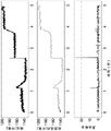
An example time series output from the optical proximity sensor 29 during triggering of the internal mechanism of the inhaler is shown in the top graph of figure 16. The optical proximity sensor 29 count (baseline reading) from around 1140 rises abruptly around 2.5s to above 1160, producing a signal level difference (contrast) of over 20. Due to the mechanical forces generated by the manual handling of the powder inhaler assembly and moving the nozzle cover 5 directly linked to the position of the shuttle 13, changes in the output of the sensor can also be observed in the figure at 1.2s and 3.8 s.
In order to distinguish these signals from the signals caused by the state transitions of the metering device 10 and the suction-actuated mechanism 15, signal processing algorithms are implemented within the microprocessor. This algorithm can be considered a type of "edge detector" because it is tuned to respond to a rapid positive signal increase caused by the transitional movement of the extension 20 of the coupling member 17 and the protective member 14 when the powder inhaler 2 is triggered to release a metered dose.
The algorithm performs the following tasks:
-running a median filter on the last seven samples, wherein the median filter output selects the fourth element after sorting the samples in ascending order;
-subtracting the previous median filter output from the current median filter output; this requires a previously valid median filter output to produce a value;
-comparing the value obtained above with a threshold value, and determining "triggered" if the value is greater than the threshold value, and determining "not triggered" otherwise.
Fig. 16 shows the filtered signal as a function of received reflected light (middle graph) and the output signal of the algorithm over time (lower graph). As shown in the lower graph of fig. 16, the triggering of the mechanism 15 and metering device 10 to inhale actuation at approximately 2.5s on the graph results in a sharp spike in the output of the algorithm above 20 counts, which is detected as a successful actuation.
The above described behaviour means that if the electronic module 3 is correctly attached to the powder inhaler 2 and the position of the internal mechanism (mainly the shuttle 13, the extension 20 and the protective member 14) is actively monitored so that it can capture the rapid transition that occurs when the inspiratory flow triggers the release of the drug, then the electronic module 3 can conclude that the metered dose of the drug formulation was successfully released.
The electronic module 3 may be provided with an indicator 36, such as an LED indicator, operatively connected to the Printed Circuit Board (PCB)28 and positioned on the housing 24 for viewing by a user. These indicators may provide information about the status of the powder inhaler 2. For example, the indicator may signal whether the electronic module 3 is correctly attached to the powder inhaler 2 and/or successfully releases the metered dose of medicament and/or whether the electronic module 3 is wirelessly connected to an external device and/or whether the lid 5 is open or closed.
In some embodiments, not shown, to improve the optical detection of the moving parts and configurations of the metrology device 10, the shuttle 13 and/or the protective member 14 and/or the coupling member 17 have at least one diffusely reflective mark or specularly reflective mark that is readily detectable by the optical proximity sensor 29. For example, a diffuse reflection mark may be attached to the specular reflection surface of the protective member 14 in a manner facing the optical proximity sensor 29.
In some other embodiments not shown, the position of the optical proximity sensor 29 relative to the metrology device 10 may be different from that shown in fig. 5-10, such that one or more detected parts of the metrology device 10 may also be different. Referring to fig. 6, 8 or 10, the optical proximity sensor 29 may be placed a little further to the left of the Printed Circuit Board (PCB) 28. In one embodiment, when the metering device 10 is in the standby state, the emitted light hits the transparent protective member 14 and is primarily reflected by the transparent protective member 14 (which reflects light in a specular manner), and when the metering device 10 is in the trigger state, the emitted light hits the diffusely reflective indicia of the protective member 14 and is primarily reflected thereby. In one embodiment, when the metering device 10 is in the standby state, the emitted light hits the transparent protective member 14 and is mainly reflected by the transparent protective member 14 (which reflects light in a specular manner), and when the metering device 10 is in the trigger state, the emitted light hits the coupling member 17 and is mainly reflected by the coupling member 17 (which reflects light in a diffuse manner). In one embodiment, when the metering device 10 is in the standby state, none of the emitted light hits, and when the metering device 10 is in the activated state, the emitted light hits and is primarily reflected by the diffusely reflective indicia of the protective member 14.
In some other embodiments, not shown, a pinhole sensor cover (cover provided with a micro-aperture) and/or at least one lens (not shown) may be interposed between the optical proximity sensor 29 and the at least one portion of the metrology device 10. The pinhole sensor cover and/or the lens may be located in the plastic housing 24 of the electronic module 3 or in the housing 4 of the powder inhaler 2. These elements may be useful to better detect signal changes due to movement of the metrology device 10.
The pinhole sensor cover is used to alter the original field of view (optical mask) of the optical proximity sensor 29 (in addition to or in place of the shape and/or size of the window 23 of the housing 4 and/or the window 27 of the plastic housing 24).
Lenses are used to redirect and/or re-image the emitted and/or reflected light. The emitted light may be better focused on the target portion of the metrology device 10. The reflected light can be better re-imaged on the light receiver.
The optical proximity sensor 29 or electronic control unit of other embodiments may include a lock-in amplifier configured to remove noise, particularly noise due to the contribution of light signals (e.g., ambient light) from outside the housing. Lock-in amplifiers are known per se and are a type of amplifier that can extract a signal with a known carrier from a noisy environment.