Detailed Description
In addition to the foregoing problem that a certain task on the device a cannot be actively selected on the device B, through the relay function, the device B only pushes the task currently being performed by the device a to the user, and the user cannot continue to process the task that has been currently closed on the device a through the device B, that is, the scalability of the relay function is poor, which also affects the convenience of the user. Therefore, the embodiment of the application provides an interaction method for cross-device task processing, so as to improve convenience of a user in cross-device task processing.
Referring to fig. 1, fig. 1 is a schematic diagram illustrating an architecture of a multi-device system according to an embodiment of the present disclosure. The system may include at least two electronic devices. For example, in fig. 1, the multi-device system includes a device 101, a device 102, and a device 103.
The electronic device in the embodiment of the present application includes but is not limited to: a mobile phone (mobile phone), a tablet computer (Pad), a personal computer, a Virtual Reality (VR) terminal device, an Augmented Reality (AR) terminal device, a wearable device, a television, a vehicle-mounted terminal device, and the like. For example, in the example shown in fig. 1, device 101 is a cell phone, device 102 is a tablet computer, and device 103 is a television.
The electronic equipment in the embodiment of the application is provided with an input and output device so as to receive an operation instruction input by a user through operation and display information to the user. The input and output device may be a variety of devices that are independent, for example, the input device may be a keyboard, a mouse, etc., and the output device may be a display screen, etc. The input and output device may also be integrated in a device, such as a touch screen display. The form of the input/output device is not limited in the present application.
The input output device may display a User Interface (UI) for interaction with a user. The user interface is a medium interface for interaction and information exchange between an application program or an operating system and a user, and realizes conversion between an internal form of information and a form acceptable to the user. Generally, a user interface of an application is source code written in a specific computer language such as java (java) and extensible markup language (XML), and the interface source code is parsed and rendered on a terminal device, and finally presented as content that can be recognized by a user, such as a control such as a picture, a text, a button, and the like. Controls, also called widgets, are basic elements of user interfaces, and typically have a toolbar (toolbar), menu bar (menu bar), text box (text box), button (button), scroll bar (scrollbar), picture, and text. The properties and contents of the controls in the user interface are defined by tags or nodes, such as XML defining the controls contained by the interface by nodes < Textview >, < ImgView >, < VideoView >, and the like. A node is applied to a control or attribute in the user interface, and the node is displayed as content visible to the user after being analyzed and rendered. In addition, many applications, such as hybrid applications (hybrid applications), typically include web pages in their user interfaces. A web page, also called a page, can be understood as a special control embedded in the user interface of an application, the web page is source code written in a specific computer language, such as hypertext markup language (HTML), Cascading Style Sheets (CSS), java script (JavaScript, JS), etc., and the web page source code can be loaded and displayed as content recognizable to a user by a browser or a web page display component similar to a browser function. The specific content contained in the web page is also defined by tags or nodes in the source code of the web page, such as HTML, which defines elements and attributes of the web page by < p >, < img >, < video >, < canvas >.
A commonly used presentation form of the user interface is a Graphical User Interface (GUI), which refers to a user interface related to the operation of the electronic device and displayed in a graphical manner. It may be an interface element such as a window, control, etc. displayed in the display screen of the electronic device, where the control may include a visual interface element such as an icon, button, menu, tab, text box, dialog box, status bar, navigation bar, Widget, etc.
Referring now to an exemplary electronic device 100 provided in embodiments of the present application, device 101, device 102, or device 103 of fig. 1 may be electronic devices that employ the same or similar structure. Fig. 2A is a schematic structural diagram of an exemplary electronic device in the present application.
The electronic device 100 may include a processor 110, an external memory interface 120, an internal memory 121, a Universal Serial Bus (USB) interface 130, a charging management module 140, a power management module 141, a battery 142, an antenna 1, an antenna 2, a mobile communication module 150, a wireless communication module 160, an audio module 170, a speaker 170A, a receiver 170B, a microphone 170C, an earphone interface 170D, a sensor module 180, a key 190, a motor 191, an indicator 192, a camera 193, a display screen 194, a Subscriber Identification Module (SIM) card interface 195, and the like. The sensor module 180 may include a pressure sensor 180A, a gyroscope sensor 180B, an air pressure sensor 180C, a magnetic sensor 180D, an acceleration sensor 180E, a distance sensor 180F, a proximity light sensor 180G, a fingerprint sensor 180H, a temperature sensor 180J, a touch sensor 180K, an ambient light sensor 180L, a bone conduction sensor 180M, and the like.
It is to be understood that the illustrated structure of the present application does not constitute a specific limitation to the electronic device 100. In other embodiments of the present application, electronic device 100 may include more or fewer components than shown, or some components may be combined, some components may be split, or a different arrangement of components. The illustrated components may be implemented in hardware, software, or a combination of software and hardware.
Processor 110 may include one or more processing units, such as: the processor 110 may include an Application Processor (AP), a modem processor, a Graphics Processing Unit (GPU), an Image Signal Processor (ISP), a controller, a memory, a video codec, a Digital Signal Processor (DSP), a baseband processor, and/or a neural-Network Processing Unit (NPU), etc. The different processing units may be separate devices or may be integrated into one or more processors. In some embodiments, the electronic device 100 may also include one or more processors 110.
Wherein the controller may be a neural center and a command center of the electronic device 100. The controller can generate an operation control signal according to the instruction operation code and the time sequence signal to complete the control of detecting the instruction and the like.
A memory may also be provided in processor 110 for storing instructions and data. In some embodiments, the memory in the processor 110 is a cache memory. The memory may hold instructions or data that have just been used or recycled by the processor 110. If the processor 110 needs to use the instruction or data again, it can be called directly from the memory. Avoiding repeated accesses reduces the latency of the processor 110, thereby increasing the efficiency of the electronic device 100.
In some embodiments, processor 110 may include one or more interfaces. The interface may include an integrated circuit (I2C) interface, an integrated circuit built-in audio (I2S) interface, a Pulse Code Modulation (PCM) interface, a universal asynchronous receiver/transmitter (UART) interface, a mobile industry processor interface (mobile industry processor interface, MIPI), a general-purpose-input/output (GPIO) interface, a Subscriber Identity Module (SIM) interface, a bus or Universal Serial Bus (USB) interface, and the like.
The I2C interface is a bi-directional synchronous serial bus that includes a serial data line (SDA) and a Serial Clock Line (SCL). In some embodiments, processor 110 may include multiple sets of I2C buses. The processor 110 may be coupled to the touch sensor 180K, the charger, the flash, the camera 193, etc. through different I2C bus interfaces, respectively. For example: the processor 110 may be coupled to the touch sensor 180K via an I2C interface, such that the processor 110 and the touch sensor 180K communicate via an I2C bus interface to implement the touch functionality of the electronic device 100.
The I2S interface may be used for audio communication. In some embodiments, processor 110 may include multiple sets of I2S buses. The processor 110 may be coupled to the audio module 170 via an I2S bus to enable communication between the processor 110 and the audio module 170. In some embodiments, the audio module 170 may communicate audio signals to the wireless communication module 160 via the I2S interface, enabling answering of calls via a bluetooth headset.
The PCM interface may also be used for audio communication, sampling, quantizing and encoding analog signals. In some embodiments, the audio module 170 and the wireless communication module 160 may be coupled by a PCM bus interface. In some embodiments, the audio module 170 may also transmit audio signals to the wireless communication module 160 through the PCM interface, so as to implement a function of answering a call through a bluetooth headset. Both the I2S interface and the PCM interface may be used for audio communication.
The UART interface is a universal serial data bus used for asynchronous communications. The bus may be a bidirectional communication bus. It converts the data to be transmitted between serial communication and parallel communication. In some embodiments, a UART interface is generally used to connect the processor 110 with the wireless communication module 160. For example: the processor 110 communicates with a bluetooth module in the wireless communication module 160 through a UART interface to implement a bluetooth function. In some embodiments, the audio module 170 may transmit the audio signal to the wireless communication module 160 through a UART interface, so as to realize the function of playing music through a bluetooth headset.
MIPI interfaces may be used to connect processor 110 with peripheral devices such as display screen 194, camera 193, and the like. The MIPI interface includes a Camera Serial Interface (CSI), a Display Serial Interface (DSI), and the like. In some embodiments, processor 110 and camera 193 communicate through a CSI interface to implement the capture functionality of electronic device 100. The processor 110 and the display screen 194 communicate through the DSI interface to implement the display function of the electronic device 100.
The GPIO interface may be configured by software. The GPIO interface may be configured as a control signal and may also be configured as a data signal. In some embodiments, a GPIO interface may be used to connect the processor 110 with the camera 193, the display 194, the wireless communication module 160, the audio module 170, the sensor module 180, and the like. The GPIO interface may also be configured as an I2C interface, an I2S interface, a UART interface, a MIPI interface, and the like.
The USB interface 130 is an interface conforming to the USB standard specification, and may specifically be a Mini USB interface, a Micro USB interface, a USB Type C interface, or the like. The USB interface 130 may be used to connect a charger to charge the electronic device 100, and may also be used to transmit data between the electronic device 100 and a peripheral device. And the method can also be used for connecting a headset and playing audio through the headset. The interface may also be used to connect other electronic devices, such as AR devices and the like.
It should be understood that the interface connection relationship between the modules illustrated in the present application is only an exemplary illustration, and does not constitute a limitation on the structure of the electronic device 100. In other embodiments, the electronic device 100 may also adopt different interface connection manners or a combination of multiple interface connection manners in the above embodiments.
The charging management module 140 is configured to receive charging input from a charger. The charger may be a wireless charger or a wired charger. In some wired charging embodiments, the charging management module 140 may receive charging input from a wired charger via the USB interface 130. In some wireless charging embodiments, the charging management module 140 may receive a wireless charging input through a wireless charging coil of the electronic device 100. The charging management module 140 may also supply power to the electronic device through the power management module 141 while charging the battery 142.
The power management module 141 is used to connect the battery 142, the charging management module 140 and the processor 110. The power management module 141 receives input from the battery 142 and/or the charge management module 140 and provides power to the processor 110, the internal memory 121, the external memory, the display 194, the camera 193, the wireless communication module 160, and the like. The power management module 141 may also be used to monitor parameters such as battery capacity, battery cycle count, battery state of health (leakage, impedance), etc. In some other embodiments, the power management module 141 may also be disposed in the processor 110. In other embodiments, the power management module 141 and the charging management module 140 may be disposed in the same device.
The wireless communication function of the electronic device 100 may be implemented by the antenna 1, the antenna 2, the mobile communication module 150, the wireless communication module 160, a modem processor, a baseband processor, and the like.
The antennas 1 and 2 are used for transmitting and receiving electromagnetic wave signals. Each antenna in the electronic device 100 may be used to cover a single or multiple communication bands. Different antennas can also be multiplexed to improve the utilization of the antennas. For example: the antenna 1 may be multiplexed as a diversity antenna of a wireless local area network. In other embodiments, the antenna may be used in conjunction with a tuning switch.
The mobile communication module 150 may provide a solution including 2G/3G/4G/5G wireless communication applied to the electronic device 100. The mobile communication module 150 may include at least one filter, a switch, a power amplifier, a Low Noise Amplifier (LNA), and the like. The mobile communication module 150 may receive the electromagnetic wave from the antenna 1, filter, amplify, etc. the received electromagnetic wave, and transmit the electromagnetic wave to the modem processor for demodulation. The mobile communication module 150 may also amplify the signal modulated by the modem processor, and convert the signal into electromagnetic wave through the antenna 1 to radiate the electromagnetic wave. In some embodiments, at least some of the functional modules of the mobile communication module 150 may be disposed in the processor 110. In some embodiments, at least some of the functional modules of the mobile communication module 150 may be disposed in the same device as at least some of the modules of the processor 110.
The modem processor may include a modulator and a demodulator. The modulator is used for modulating a low-frequency baseband signal to be transmitted into a medium-high frequency signal. The demodulator is used for demodulating the received electromagnetic wave signal into a low-frequency baseband signal. The demodulator then passes the demodulated low frequency baseband signal to a baseband processor for processing. The low frequency baseband signal is processed by the baseband processor and then transferred to the application processor. The application processor outputs a sound signal through an audio device (not limited to the speaker 170A, the receiver 170B, etc.) or displays an image or video through the display screen 194. In some embodiments, the modem processor may be a stand-alone device. In other embodiments, the modem processor may be provided in the same device as the mobile communication module 150 or other functional modules, independent of the processor 110.
The wireless communication module 160 may provide a solution for wireless communication applied to the electronic device 100, including Wireless Local Area Networks (WLANs) (e.g., wireless fidelity (Wi-Fi) networks), bluetooth (bluetooth, BT), Global Navigation Satellite System (GNSS), Frequency Modulation (FM), Near Field Communication (NFC), Infrared (IR), and the like. The wireless communication module 160 may be one or more devices integrating at least one communication processing module. The wireless communication module 160 receives electromagnetic waves via the antenna 2, performs frequency modulation and filtering processing on electromagnetic wave signals, and transmits the processed signals to the processor 110. The wireless communication module 160 may also receive a signal to be transmitted from the processor 110, perform frequency modulation and amplification on the signal, and convert the signal into electromagnetic waves through the antenna 2 to radiate the electromagnetic waves.
In some embodiments, antenna 1 of electronic device 100 is coupled to mobile communication module 150 and antenna 2 is coupled to wireless communication module 160 so that electronic device 100 can communicate with networks and other devices through wireless communication techniques. The wireless communication technology may include global system for mobile communications (GSM), General Packet Radio Service (GPRS), code division multiple access (code division multiple access, CDMA), Wideband Code Division Multiple Access (WCDMA), time-division code division multiple access (time-division code division multiple access, TD-SCDMA), Long Term Evolution (LTE), LTE, BT, GNSS, WLAN, NFC, FM, and/or IR technologies, etc. The GNSS may include a Global Positioning System (GPS), a global navigation satellite system (GLONASS), a beidou navigation satellite system (BDS), a quasi-zenith satellite system (QZSS), and/or a Satellite Based Augmentation System (SBAS).
In some embodiments, the solution for wireless communication provided by the mobile communication module 150 may enable the electronic device to communicate with a device in a network (e.g., a cloud server), and the solution for WLAN wireless communication provided by the wireless communication module 160 may also enable the electronic device to communicate with a device in a network (e.g., a cloud server). Therefore, the electronic equipment can perform data transmission with the cloud server.
The electronic device 100 may implement display functions through the display screen 194, and the application processor, etc. The display screen 194 is used to display controls, information, images, and the like. The display screen 194 includes a display panel. The display panel may adopt a Liquid Crystal Display (LCD), an organic light-emitting diode (OLED), an active-matrix organic light-emitting diode (active-matrix organic light-emitting diode, AMOLED), a flexible light-emitting diode (FLED), a miniature, a Micro-oeld, a quantum dot light-emitting diode (QLED), and the like.
The electronic device 100 may implement a shooting function through the ISP, the camera 193, the video codec, the GPU, the display 194, the application processor, and the like.
The ISP is used to process the data fed back by the camera 193. For example, when a photo is taken, the shutter is opened, light is transmitted to the camera photosensitive element through the lens, the optical signal is converted into an electrical signal, and the camera photosensitive element transmits the electrical signal to the ISP for processing and converting into an image visible to naked eyes. The ISP can also carry out algorithm optimization on the noise, brightness and skin color of the image. The ISP can also optimize parameters such as exposure, color temperature and the like of a shooting scene. In some embodiments, the ISP may be provided in camera 193.
The camera 193 is used to capture still images or video. The object generates an optical image through the lens and projects the optical image to the photosensitive element. The photosensitive element may be a Charge Coupled Device (CCD) or a complementary metal-oxide-semiconductor (CMOS) phototransistor. The light sensing element converts the optical signal into an electrical signal, which is then passed to the ISP where it is converted into a digital image signal. And the ISP outputs the digital image signal to the DSP for processing. The DSP converts the digital image signal into an image signal in a standard RGB, YUV and other formats. In some embodiments, electronic device 100 may include 1 or N cameras 193, N being a positive integer greater than 1.
The digital signal processor is used for processing digital signals, and can process digital image signals and other digital signals. For example, when the electronic device 100 selects a frequency bin, the digital signal processor is used to perform fourier transform or the like on the frequency bin energy.
Video codecs are used to compress or decompress digital video. The electronic device 100 may support one or more video codecs. In this way, the electronic device 100 may play or record video in a variety of encoding formats, such as: moving Picture Experts Group (MPEG) -1, MPEG-2, MPEG-3, MPEG-4, and the like.
The NPU is a neural-network (NN) computing processor that processes input information quickly by using a biological neural network structure, for example, by using a transfer mode between neurons of a human brain, and can also learn by itself continuously. Applications such as intelligent recognition of the electronic device 100 can be realized through the NPU, for example: image recognition, face recognition, speech recognition, text understanding, and the like.
The external memory interface 120 may be used to connect an external memory card, such as a Micro SD card, to extend the memory capability of the electronic device 100. The external memory card communicates with the processor 110 through the external memory interface 120 to implement a data storage function. For example, data such as music, photos, videos, and the like are stored in the external memory card.
Internal memory 121 may be used to store one or more computer programs, including instructions. The processor 110 may execute the above-mentioned instructions stored in the internal memory 121, so as to enable the electronic device 100 to perform a message display method provided in some embodiments of the present application, and various functional applications, data processing, and the like. The internal memory 121 may include a program storage area and a data storage area. Wherein, the storage program area can store an operating system; the storage area may also store one or more application programs (e.g., gallery, contacts, etc.), etc. The storage data area may store data created during use of the electronic device 100. In addition, the internal memory 121 may include a high-speed random access memory, and may further include a nonvolatile memory, such as at least one magnetic disk storage device, a flash memory device, a universal flash memory (UFS), and the like.
The electronic device 100 may implement audio functions via the audio module 170, the speaker 170A, the receiver 170B, the microphone 170C, the headphone interface 170D, and the application processor. Such as music playing, recording, etc.
The audio module 170 is used to convert digital audio information into an analog audio signal output and also to convert an analog audio input into a digital audio signal. The audio module 170 may also be used to encode and decode audio signals. In some embodiments, the audio module 170 may be disposed in the processor 110, or some functional modules of the audio module 170 may be disposed in the processor 110.
The speaker 170A, also called a "horn", is used to convert the audio electrical signal into an acoustic signal. The electronic apparatus 100 can listen to music through the speaker 170A or listen to a handsfree call.
The receiver 170B, also called "earpiece", is used to convert the electrical audio signal into an acoustic signal. When the electronic apparatus 100 receives a call or voice information, it can receive voice by placing the receiver 170B close to the ear of the person.
The microphone 170C, also referred to as a "microphone," is used to convert sound signals into electrical signals. When making a call or transmitting voice information, the user can input a voice signal to the microphone 170C by speaking the user's mouth near the microphone 170C. The electronic device 100 may be provided with at least one microphone 170C. In other embodiments, the electronic device 100 may be provided with two microphones 170C to achieve a noise reduction function in addition to collecting sound signals. In other embodiments, the electronic device 100 may further include three, four or more microphones 170C to collect sound signals, reduce noise, identify sound sources, perform directional recording, and so on.
The headphone interface 170D is used to connect a wired headphone. The headset interface 170D may be the USB interface 130, or may be a 3.5mm open mobile electronic device platform (OMTP) standard interface, a cellular telecommunications industry association (cellular telecommunications industry association of the USA, CTIA) standard interface.
The pressure sensor 180A is used for sensing a pressure signal, and converting the pressure signal into an electrical signal. In some embodiments, the pressure sensor 180A may be disposed on the display screen 194. The pressure sensor 180A can be of a wide variety, such as a resistive pressure sensor, an inductive pressure sensor, a capacitive pressure sensor, and the like. The capacitive pressure sensor may be a sensor comprising at least two parallel plates having an electrically conductive material. When a force acts on the pressure sensor 180A, the capacitance between the electrodes changes. The electronic device 100 determines the strength of the pressure from the change in capacitance. When a touch operation is applied to the display screen 194, the electronic apparatus 100 detects the intensity of the touch operation according to the pressure sensor 180A. The electronic apparatus 100 may also calculate the touched position from the detection signal of the pressure sensor 180A. In some embodiments, the touch operations that are applied to the same touch position but different touch operation intensities may correspond to different operation instructions. For example: and when the touch operation with the touch operation intensity smaller than the first pressure threshold value acts on the short message application icon, executing an instruction for viewing the short message. And when the touch operation with the touch operation intensity larger than or equal to the first pressure threshold value acts on the short message application icon, executing an instruction of newly building the short message.
The gyro sensor 180B may be used to determine the motion attitude of the electronic device 100. In some embodiments, the angular velocity of electronic device 100 about three axes (i.e., the x, y, and z axes) may be determined by gyroscope sensor 180B. The gyro sensor 180B may be used for photographing anti-shake. For example, when the shutter is pressed, the gyro sensor 180B detects a shake angle of the electronic device 100, calculates a distance to be compensated for by the lens module according to the shake angle, and allows the lens to counteract the shake of the electronic device 100 through a reverse movement, thereby achieving anti-shake. The gyroscope sensor 180B may also be used for navigation, somatosensory gaming scenes.
The air pressure sensor 180C is used to measure air pressure. In some embodiments, electronic device 100 calculates altitude, aiding in positioning and navigation, from barometric pressure values measured by barometric pressure sensor 180C.
The magnetic sensor 180D includes a hall sensor. The electronic device 100 may detect the opening and closing of the flip holster using the magnetic sensor 180D. In some embodiments, when the electronic device 100 is a flip, the electronic device 100 may detect the opening and closing of the flip according to the magnetic sensor 180D. And then according to the opening and closing state of the leather sheath or the opening and closing state of the flip cover, the automatic unlocking of the flip cover is set.
The acceleration sensor 180E may detect the magnitude of acceleration of the electronic device 100 in various directions (typically three axes). The magnitude and direction of gravity can be detected when the electronic device 100 is stationary. The method can also be used for identifying the posture of the electronic equipment, and is applied to horizontal and vertical screen switching, pedometers and the like.
A distance sensor 180F for measuring a distance. The electronic device 100 may measure the distance by infrared or laser. In some embodiments, taking a picture of a scene, electronic device 100 may utilize range sensor 180F to range for fast focus.
The proximity light sensor 180G may include, for example, a Light Emitting Diode (LED) and a light detector, such as a photodiode. The light emitting diode may be an infrared light emitting diode. The electronic device 100 emits infrared light to the outside through the light emitting diode. The electronic device 100 detects infrared reflected light from nearby objects using a photodiode. When sufficient reflected light is detected, it can be determined that there is an object near the electronic device 100. When insufficient reflected light is detected, the electronic device 100 may determine that there are no objects near the electronic device 100. The electronic device 100 can utilize the proximity light sensor 180G to detect that the user holds the electronic device 100 close to the ear for talking, so as to automatically turn off the screen to achieve the purpose of saving power. The proximity light sensor 180G may also be used in a holster mode, a pocket mode automatically unlocks and locks the screen.
The ambient light sensor 180L is used to sense the ambient light level. Electronic device 100 may adaptively adjust the brightness of display screen 194 based on the perceived ambient light level. The ambient light sensor 180L may also be used to automatically adjust the white balance when taking a picture. The ambient light sensor 180L may also cooperate with the proximity light sensor 180G to detect whether the electronic device 100 is in a pocket to prevent accidental touches.
The fingerprint sensor 180H is used to collect a fingerprint. The electronic device 100 can utilize the collected fingerprint characteristics to unlock the fingerprint, access the application lock, photograph the fingerprint, answer an incoming call with the fingerprint, and so on.
The temperature sensor 180J is used to detect temperature. In some embodiments, electronic device 100 implements a temperature processing strategy using the temperature detected by temperature sensor 180J. For example, when the temperature reported by the temperature sensor 180J exceeds a threshold, the electronic device 100 performs a reduction in performance of a processor located near the temperature sensor 180J, so as to reduce power consumption and implement thermal protection. In other embodiments, the electronic device 100 heats the battery 142 when the temperature is below another threshold to avoid the low temperature causing the electronic device 100 to shut down abnormally. In other embodiments, when the temperature is lower than a further threshold, the electronic device 100 performs boosting on the output voltage of the battery 142 to avoid abnormal shutdown due to low temperature.
Touch sensor 180K, may also be referred to as a touch panel or touch sensitive surface. The touch sensor 180K may be disposed on the display screen 194, and the touch sensor 180K and the display screen 194 form a touch screen, which is also called a "touch screen". The touch sensor 180K is used to detect a touch operation applied thereto or nearby. The touch sensor can communicate the detected touch operation to the application processor to determine the touch event type. Visual output associated with the touch operation may be provided through the display screen 194. In other embodiments, the touch sensor 180K may be disposed on a surface of the electronic device 100, different from the position of the display screen 194.
The bone conduction sensor 180M can acquire a vibration signal. In some embodiments, the bone conduction sensor 180M may acquire a vibration signal of the human vocal part vibrating the bone mass. The bone conduction sensor 180M may also contact the human pulse to receive the blood pressure pulsation signal. In some embodiments, the bone conduction sensor 180M may also be disposed in a headset, integrated into a bone conduction headset. The audio module 170 may analyze a voice signal based on the vibration signal of the bone mass vibrated by the sound part acquired by the bone conduction sensor 180M, so as to implement a voice function. The application processor can analyze heart rate information based on the blood pressure beating signal acquired by the bone conduction sensor 180M, so as to realize the heart rate detection function.
The keys 190 include a power-on key, a volume key, and the like. The keys 190 may be mechanical keys. Or may be touch keys. The electronic apparatus 100 may receive a key input, and generate a key signal input related to user setting and function control of the electronic apparatus 100.
The motor 191 may generate a vibration cue. The motor 191 may be used for incoming call vibration cues, as well as for touch vibration feedback. For example, touch operations applied to different applications (e.g., photographing, audio playing, etc.) may correspond to different vibration feedback effects. The motor 191 may also respond to different vibration feedback effects for touch operations applied to different areas of the display screen 194. Different application scenes (such as time reminding, receiving information, alarm clock, game and the like) can also correspond to different vibration feedback effects. The touch vibration feedback effect may also support customization.
Indicator 192 may be an indicator light that may be used to indicate a state of charge, a change in charge, or a message, missed call, notification, etc.
The SIM card interface 195 is used to connect a SIM card. The SIM card can be brought into and out of contact with the electronic apparatus 100 by being inserted into the SIM card interface 195 or being pulled out of the SIM card interface 195. The electronic device 100 may support 1 or N SIM card interfaces, N being a positive integer greater than 1. The SIM card interface 195 may support a Nano SIM card, a Micro SIM card, a SIM card, etc. Multiple cards can be inserted into the same SIM card interface 195 at the same time. The types of the plurality of cards can be the same or different. The SIM card interface 195 may also be compatible with different types of SIM cards. The SIM card interface 195 may also be compatible with external memory cards. The electronic device 100 interacts with the network through the SIM card to implement functions such as communication and data communication. In some embodiments, the electronic device 100 employs esims, namely: an embedded SIM card. The eSIM card can be embedded in the electronic device 100 and cannot be separated from the electronic device 100.
In the exemplary electronic apparatus 100 shown in fig. 2A, the display screen 194, the touch sensor 180K, the key 190, and the like may serve as input and output devices. The electronic device 100 may display various user interfaces, such as a multitasking management interface, an interface for other applications, and the like, described in various embodiments below, via the display screen 194. The electronic apparatus 100 may detect a user operation, such as clicking, dragging, sliding up or down, etc., in each user interface through the touch sensor 180K, thereby receiving an operation instruction input by the user. The electronic device 100 may detect a user operation through the key 190, such as a long press, a continuous press, and the like, and receive an operation instruction input by the user.
The software system of the electronic device 100 may employ a layered architecture, an event-driven architecture, a micro-core architecture, a micro-service architecture, or a cloud architecture. The application takes an Android system with a layered architecture as an example to exemplarily illustrate a software structure of the electronic device 100. Fig. 2B is a block diagram of a software structure of the electronic device 100 according to the present application.
The layered architecture divides the software into several layers, each layer having a clear role and division of labor. The layers communicate with each other through a software interface. In some embodiments, the Android system is divided into four layers, an application layer, an application framework layer, an Android runtime (Android runtime) and system library, and a kernel layer from top to bottom.
The application layer may include a series of application packages. As shown in fig. 2B, the application package may include applications such as camera, gallery, talk, navigation, bluetooth, music, video, short message, etc.
The application framework layer provides an Application Programming Interface (API) and a programming framework for the application program of the application layer. The application framework layer includes a number of predefined functions. As shown in FIG. 2B, the application framework layers may include a window manager, content provider, view system, phone manager, resource manager, notification manager, and the like.
The window manager is used for managing window programs. The window manager can obtain the size of the display screen, judge whether a status bar exists, lock the screen, intercept the screen and the like.
The content provider is used to store and retrieve data and make it accessible to applications. The data may include video, images, audio, calls made and received, browsing history and bookmarks, phone books, etc.
The view system includes visual controls such as controls to display text, controls to display pictures, and the like. The view system may be used to build applications. The display interface may be composed of one or more views. For example, the display interface including the short message notification icon may include a view for displaying text and a view for displaying pictures.
The phone manager is used to provide communication functions of the electronic device 100. Such as management of call status (including on, off, etc.).
The resource manager provides various resources for the application, such as localized strings, icons, pictures, layout files, video files, and the like.
The notification manager enables the application to display notification information in the status bar, can be used to convey notification-type messages, can disappear automatically after a short dwell, and does not require user interaction. Such as a notification manager used to notify download completion, message alerts, etc. The notification manager may also be a notification that appears in the form of a chart or scroll bar text at the top status bar of the system, such as a notification of a background running application, or a notification that appears on the screen in the form of a dialog window. For example, prompting text information in the status bar, sounding a prompt tone, vibrating the electronic device, flashing an indicator light, etc.
The Android Runtime comprises a core library and a virtual machine. The Android runtime is responsible for scheduling and managing an Android system.
The core library comprises two parts: one part is a function which needs to be called by java language, and the other part is a core library of android.
The application layer and the application framework layer run in a virtual machine. And executing java files of the application program layer and the application program framework layer into a binary file by the virtual machine. The virtual machine is used for performing the functions of object life cycle management, stack management, thread management, safety and exception management, garbage collection and the like.
The system library may include a plurality of functional modules. For example: surface managers (surface managers), media libraries (media libraries), three-dimensional graphics processing libraries (e.g., OpenGL ES), 2D graphics engines (e.g., SGL), and the like.
The surface manager is used to manage the display subsystem and provide a fusion of the 2D and 3D layers for multiple applications.
The media library supports a variety of commonly used audio, video format playback and recording, and still image files, among others. The media library may support a variety of audio-video encoding formats, such as: MPEG4, H.264, MP3, AAC, AMR, JPG, PNG, etc.
The three-dimensional graphic processing library is used for realizing three-dimensional graphic drawing, image rendering, synthesis, layer processing and the like.
The 2D graphics engine is a drawing engine for 2D drawing.
The kernel layer is a layer between hardware and software. The inner core layer at least comprises a display driver, a camera driver, an audio driver and a sensor driver.
In the system, at least one electronic device may acquire task history records of other electronic devices in the system, so as to execute the interaction method of the present application.
In one implementation manner, at least one electronic device in the system establishes communication connection with other electronic devices respectively so as to acquire task history records of the other electronic devices.
In another implementation, the system may further include a server. The server can be a cloud server, a common server and the like, and the application does not limit the server. In this implementation manner, all the electronic devices in the system are in communication connection with the server, and synchronize their respective task histories to the server, so that any one of the electronic devices in the system can obtain the task histories of the other electronic devices through the server. For example, in the example shown in fig. 1, the device 101, the device 102, and the device 103 are respectively connected to the cloud server 104 in a communication manner, and synchronize their respective task histories to the cloud server 104.
Optionally, when the system further includes a server, the plurality of electronic devices may synchronize their respective task histories to the server by logging in to the same user account, so that the plurality of electronic devices logging in to the same user account can obtain their task histories from the server. The user account in the embodiment of the present application may be a character string that distinguishes identities of different users, such as a mailbox address, a cloud service account, and the like.
In order to facilitate understanding of the technical solution of the present application, several concepts involved in the embodiments of the present application, including tasks, task history records, task records, cross-device task processing, and the like, are briefly described below.
Applications are run in electronic devices for specific purposes, these running applications are also referred to as tasks. For example, if a user opens a browser in the electronic device to browse a web page, the running browser may be considered a task. For another example, if a user opens a video player in an electronic device to play a video, the running video player may be considered a task. It should be noted that the tasks in the embodiment of the present application may include tasks running in the foreground of the electronic device, and may also include tasks running in the background. These tasks may be viewing tasks, such as browsing a web page, playing a video file, etc., or editing tasks, such as editing a presentation document, a table, etc., and the application is not limited to the type of task.
The task history record includes one or more task records, each of which may record one or more tasks running on the electronic device. The user can look up the task history record of the electronic equipment on the user interface of the electronic equipment, so that the user can know the task running in the foreground or the background of the electronic equipment.
It should be noted that, if a task is executed at different time points, only the latest state of the task, that is, the state of the time point closest to the current time point, is recorded in the corresponding task record. When a task is closed, the task history record corresponding to the task is usually not kept.
For example, a user first opens a web page a in a browser of an electronic device. At this time, the task history record includes a task record corresponding to the browser, in which the state of the browser, that is, the web page a, is recorded. The user then turns on the video player again and the browser is placed to run in the background. At this time, the task history record includes two task records, one is a task record corresponding to the browser, in which a state of the browser, i.e., a web page a, is recorded, and the other is a task record corresponding to the video player, in which a state of the video player is recorded. The user then closes the video player and opens a web page B in the browser. At this time, the task history record includes a task record corresponding to the browser, the recorded state of the browser is updated to the web page B, and the task record corresponding to the video player is not retained.
It should also be noted that a task record may correspond to one or more tasks. When a task runs in the foreground or the background, a corresponding task record exists in the task history record. When a plurality of tasks enter a split screen mode and run in a foreground or a background in a split screen mode, a task record corresponding to the plurality of tasks exists in the task history record. When the plurality of tasks exit the split-screen mode, the task records corresponding to the plurality of tasks are not included in the task history record any more, but only the plurality of task records corresponding to the plurality of tasks respectively are included.
The cross-device task processing mainly refers to continuously processing a task on one electronic device (hereinafter also referred to as a target device) and another electronic device (hereinafter also referred to as a source device), that is, running a task originally running on the source device on the target device. For example, a web page opened on the source device, a video played, a document edited, or processing data transmitted from the source device, etc. may continue to run on the target device.
When one or more electronic devices in the multi-device system can acquire the task history records of other electronic devices, any one of the electronic devices can execute the interaction method for cross-device task processing provided by the application. For convenience of description, in the present application, an electronic device that executes the interaction method in the system, that is, an electronic device that a user is currently operating is referred to as a first electronic device, and other electronic devices in the system except the first electronic device are referred to as second electronic devices.
By executing the interaction method, the first electronic device can enable a user to view task history records of the first electronic device and the second electronic device on the first electronic device, and can actively select one or more tasks to realize cross-device task processing, so that the method is very convenient and fast, and can provide simple, direct and easy-to-use interaction experience for the user.
Referring to fig. 3, fig. 3 is a flowchart of an interaction method for cross-device task processing according to the present application. The interaction method in the embodiment of the present application is described below with reference to fig. 3. The interaction method is performed by the first electronic device and may include the following steps S501 to S503.
S501: the first electronic device displays a multitask management interface.
The multitask management interface comprises N equipment labels and at least one task record, the N equipment labels correspond to the N pieces of electronic equipment respectively, and N is a positive integer larger than 1.
Optionally, in an implementation manner, the first electronic device may receive a first operation of a user, and the first electronic device displays the multitask management interface in response to the first operation. The first operation is mainly used for enabling the first electronic device to display a multitask management interface. The first operation may be any operation set in advance, may be set by a user, or may be set by a system of the first electronic device, which is not limited in the present application.
S502: the first electronic device receives sharing operation of a user on a first task record in the multitask management interface.
The first task record is any one of task records of a source device, and the source device is any one of the N electronic devices.
In order to facilitate the overview of the interaction method of the present application, the concepts of the source device and the target device are introduced in the embodiments of the present application. A source device refers to an electronic device where a task that a user desires to process across devices is originally located. The target device refers to an electronic device that continues to run a task on the source device while implementing cross-device task processing.
It should be noted that, when the aforementioned N electronic devices include a first electronic device and at least one second electronic device, the source device may be any one of the first electronic device and the second electronic device, and the target device may also be any one of the first electronic device and the second electronic device, but the source device and the target device must be two different electronic devices.
The sharing operation is mainly used for enabling the target device to display the task corresponding to the first task record. The sharing operation may be any operation set in advance, may be set by a user, and may also be set by a system of the first electronic device, which is not limited in this application. According to the difference of the target devices and the difference of the display modes of the target devices, the sharing operation may include a plurality of different implementation forms, such as the subsequent second operation, the subsequent third operation, the subsequent fourth operation, the subsequent fifth operation, the subsequent sixth operation, the subsequent seventh operation, and the like. This will be further explained in the following examples.
S503: and the first electronic equipment responds to the sharing operation, so that the target equipment displays at least one task corresponding to the first task record.
As mentioned above, the target device is any one of the N electronic devices, and the target device is different from the source device.
According to different situations of whether the target device is the first electronic device, the first electronic device can realize different functions by executing the interaction method of the application, including: sharing a task on one second electronic device to the first electronic device; the task on the first electronic device is shared with a certain second electronic device, or the task on the certain second electronic device is shared with another second electronic device. The interaction method in the present application will be described below with respect to these two functions.
In the following embodiments, the interaction method of cross-device task processing according to the present application will be described by taking the device 101 as a device currently operated by a user, that is, a first electronic device, and taking the devices 102 and 103 as second electronic devices. The input/output device of the apparatus 101 is a touch display screen, and different user interfaces may be displayed on the touch display screen, and may also receive user operations.
Example one
In this embodiment, the target device is a first electronic device, and the source device is any one of second electronic devices.
Firstly, first electronic equipment receives first operation of a user; and the first electronic equipment responds to the first operation and displays a multitask management interface.
The user performs a first operation on any one of the user interfaces displayed on the display screen of the device 101. For example, the first operation may be sliding upwards from the bottom of the user interface, or sliding downwards from the top of the user interface, and the like, and the embodiment of the present application is not limited to a specific form of the first operation. The device 101 displays a multitask management interface in response to the first operation.
For example, referring to fig. 4A, fig. 4A is a first exemplary diagram of a user interface displayed by the device 101 before the first operation. As seen in fig. 4A, the user interface 201 displays a Web page "Web page a" in the browser of the device 101, and then the user slides up from the bottom of the user interface 201. After receiving the operation instruction 1, the device 101 displays the multitask management interface 290.
The multitask management interface is used for displaying N device labels corresponding to the N electronic devices respectively, wherein N is a positive integer larger than 1.
For the sake of convenience of distinction, in this embodiment, the device tag corresponding to the first electronic device (i.e., the device 101) is referred to as a first tag, and the device tag corresponding to the second electronic device (i.e., the device 102, the device 103, etc.) is referred to as a second tag. As described in step S501, the N electronic devices may not include the first electronic device, only include a plurality of second electronic devices, or include the first electronic device and at least one second electronic device. When the N pieces of electronic equipment only comprise a plurality of pieces of second electronic equipment, the equipment tags displayed in the multitask management interface are all second tags. When the N electronic devices include a first electronic device and at least one second electronic device, the device tags displayed in the multitask management interface include a first tag and a second tag. Since the purpose of this embodiment is to share one or more tasks in the task history of the second electronic device with the first electronic device, in this embodiment, the achievement of this purpose is not affected no matter whether the first tag is displayed in the multitask management interface or not.
Referring to fig. 4B, fig. 4B is a first exemplary schematic diagram of a multitask management interface of the device 101 according to the embodiment of the present application. In the example shown in fig. 4B, a first label "My phone" for device 101, a second label "Tablet" for device 102, and a second label "TV" for device 103 are displayed in the multitasking management interface 290.
The device label in the embodiment of the present application may be in the form of capsule-shaped icons and characters, for example, as shown in fig. 4B, or may be in other forms, which is not limited in the present application.
The user can change the selected device label by selecting the device label on the multitask management interface. It should be noted that, on the multitasking management interface, the states of the device tags can be distinguished through different display forms, that is, selected or unselected. In this way, the user can be made to intuitively observe the state of the device tag. The present application is not intended to be limited to the particular forms disclosed.
For example, in the example of fig. 4B, the background color of the first label "My phone" corresponding to device 101 is darker than the background color of the second label "Tablet" corresponding to device 102 and the background color of the second label "TV" corresponding to device 103, thereby indicating that the first label "My phone" has been selected, and the second labels "Tablet" and "TV" have not been selected.
The multitask management interface is further used for displaying at least one task record in the task history records of the electronic equipment corresponding to the selected equipment label.
For example, in the example of fig. 4B, since the device corresponding to the currently selected first tab "My phone" in the multitasking management interface is the device 101, the multitasking management interface also displays a task history of the device 101, including a Web page "Web page a" or the like opened in a browser on the device 101.
When the user operates on the multitask management interface to change the selected equipment label, the task history record displayed on the multitask management interface is correspondingly changed.
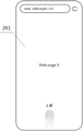
For example, please refer to fig. 4C, where fig. 4C is a second exemplary diagram of a multitask management interface of the device 101 in the embodiment of the present application. When the user clicks the second tab "Tablet" corresponding to the selected device 102 on the multitask management interface, the multitask management interface correspondingly displays the task history of the device 102, for example, a webpage "Web B" opened in a browser on the device 102.
Each task record in the task history records can be displayed in the form of a task card, and can also be displayed in other forms. For convenience of explanation, in the present embodiment and the following embodiments, the form of a task card is taken as an example, and examples thereof include a task card 2921 "Web page a" in fig. 4B, and a task card 2921 "Web page B" in fig. 4C.
Optionally, the user interface when the electronic device moves back a task from the foreground to the background may be saved in the task record corresponding to the task in the form of a thumbnail. Then, when the thumbnail needs to be displayed, the first electronic device can put the thumbnail in the corresponding task card to be displayed to the user for the user to view.
Because the task history of the electronic device corresponding to the selected device tag may include a plurality of task records, and the display screen cannot display all the task records at one time, the user can view other task records in the task history through specific operations.
For example, in the examples of fig. 4B and 4C, the user may view other task cards by sliding left and right.
Optionally, in the multitask management interface, an application label corresponding to the task record can be displayed nearby the task record to indicate an application program corresponding to the task record.
For example, in the example of FIG. 4B, a corresponding application tab 2922 is also displayed above the task card 2921 "Web page A" to indicate that the application to which the task card corresponds is a "browser".
The device label and the task history record can be displayed in the same area of the multitask management interface or different areas.
Alternatively, the multitasking management interface may comprise two zones, a first zone and a second zone. The first area is used for displaying the equipment labels, and the second area is used for displaying the task history records of the equipment corresponding to the selected equipment labels.
For example, in the example of FIG. 4B, the multitasking management interface 290 includes a first area 291 and a second area 292, the first area 291 displays three device tabs, and the second area 292 displays a task history of the device 101, including a webpage "Web Page A" opened in a browser, etc.
It should be noted that, in the multitasking management interface of the various embodiments of the present application, the first region may be above the second region, as shown in the examples of fig. 4B and 4C, or may be below the second region or at other positions. In addition, in addition to the first area and the second area, if necessary, other areas may be included in the multitasking management interface, which is not limited in this application.
Optionally, when the user inputs the first operation on the device 101 to enter the multitask management interface, the device tag corresponding to the device 101 may be selected by default in the multitask management interface, or the device tag selected by the user when exiting the multitask management interface before the user is selected by default, which is not limited in the present application. The implementation manner selected by default may be configured by the system of the device 101, or may be set by the user, which is not limited in this application.
For example, in the device 101, if the first label "My phone" corresponding to the device 101 is selected by default, each time the user enters the multitask management interface 290 of the device 101, the selected device label in the first area 291 is "My phone", and the task history of the device 101 is displayed in the second area 292, as shown in fig. 4B. Thus, when the user wants to implement the cross-device task processing, the user needs to first select the device tag of one or several of the other devices, such as the device 102 and the device 103, and then continue the subsequent operation.
For another example, in the device 101, if the device tab selected by the previous user when exiting the multitasking management interface 290 is selected by default, when the multitasking management interface 290 is currently entered, the selected device tab in the first area 291 should be the same as the device tab selected when the multitasking management interface 290 was last exited. For example, when the user previously entered the multitasking management interface 290 on the device 101, the second tag "Tablet" corresponding to the device 102 is selected, and then the multitasking management interface 290 is exited. Then, the next time the user performs the first operation on the device 101 to enter the multitasking management interface 290, the selected device tag is displayed as the second tag "Tablet", and the displayed task history is the task history of the device 102 corresponding to the "Tablet", as shown in fig. 4C. Thus, the next time the user still wishes to process the task in the device 102 across devices, the selected device tag is changed from the first tag "My phone" to the second tag "Tablet" without having to click on the selected second tag "Tablet".
Then, the first electronic equipment receives sharing operation of the user on the first task record; and the first electronic equipment responds to the sharing operation, so that the target equipment displays at least one task corresponding to the first task record.
The first task record in the embodiment of the present application is a task record corresponding to a task that a user desires to process across devices, and may be any one of task history records of a source device. In this embodiment, the source device is any one of the second electronic devices, and thus, the first task record may be any one of task records in a task history record of any one of the second electronic devices.
After determining the task record corresponding to the task expected to be processed across the devices, namely the first task record, the user can perform sharing operation on the task record, so that the first electronic device displays at least one task corresponding to the first task record.
The first electronic device displays at least one task corresponding to the first task record, and can have a plurality of different display modes. Correspondingly, the user may adopt different sharing operations, so that the first electronic device may recognize in which manner the user desires to display according to the difference of the sharing operations.
In one implementation, the user may perform a second operation on the first task record. And the first electronic equipment responds to the second operation and displays at least one task corresponding to the first task record.
The second operation may be any operation that is set in advance, for example, a click, and the embodiment of the present application does not limit a specific form of the second operation. The second operation may be a single operation or a combination of operations, and the present application is not limited thereto.
For example, in the example of fig. 4C, the user desires to share a task corresponding to the task card 2921 "Web page B" in the device 102 with the device 101 and browse on the device 101. Then the user can click on the task card 2921 "Web page B" in the second area 292 of FIG. 4C. Fig. 4D is a first exemplary schematic diagram of a user interface displayed by the device 101 after the second operation in the embodiment of the present application. In the example of fig. 4C and 4D, the device 101 displays the user interface 202, i.e., the Web page "Web page B" in the device 102, on the display screen of the device 101 in response to the second operation. In this way, the user can continue browsing the web page in device 102 on device 101, thereby enabling a single task to be processed across devices.
It should be noted that, when the first task record corresponds to a single task record, the first electronic device displays, in response to the second operation, the single task corresponding to the first task record, as shown in fig. 4D; and when the first task record corresponds to a plurality of related tasks, the first electronic equipment responds to the second operation and displays the plurality of related tasks corresponding to the first task record in a split screen mode. In the present application, a plurality of tasks that run in a split screen form in the source device are referred to as related tasks. One task record may correspond to one task, or a plurality of related tasks.
Fig. 4E is a third exemplary schematic diagram of a multitasking management interface of the device 101 in the embodiment of the present application, and fig. 4F is a second exemplary schematic diagram of a user interface displayed by the device 101 after the second operation in the embodiment of the present application. In FIG. 4E, a task card 2921 is displayed in the second region 292, where the task card 2921 indicates that one of the task records in the task history of the device 102 includes two related tasks "chat software" and "video player" displayed in a split-screen fashion. The user performs a second operation on the task card 2921, namely clicking on the task card 2921. The device 101 displays the user interface 203 on the display screen of the device 101 in response to the second operation, displaying the tasks "chat software" and "video player" in the device 102 in a split screen form, as shown in fig. 4F. In this way, the user can continue to view the chat software and watch videos on the device 101 in a split screen fashion, thereby enabling multiple tasks to be handled across devices.
It should be noted that, although a plurality of related tasks are displayed in a split screen manner, the split screen display manner of the plurality of related tasks in the first electronic device may be the same as or different from the split screen display manner in the second electronic device, and the present application does not limit this. For example, in the example shown in fig. 4E and 4F, the related tasks "chat software" and "video player" are displayed in the device 102 in a left-right split screen manner, and in the device 101 in a top-down split screen manner.
In another display mode, the user may perform a sixth operation on the first task record and the device tag corresponding to any one of the second electronic devices. And the first electronic equipment responds to the sixth operation, displays the task running in the foreground in the first electronic equipment in a split screen mode, and records at least one corresponding task by the first task.
The sixth operation may be any operation set in advance, and the specific form of the sixth operation is not limited in the embodiment of the present application. The sixth operation may be a single operation, or may be an operation combination composed of a plurality of operations, for example, long press + drag, and the like, which is not limited in this application. Generally, to avoid confusion, the sixth operation and the aforementioned second operation should be set as different operations.
For example, fig. 4G is a second exemplary schematic diagram of a user interface displayed by the device 101 before the first operation, fig. 4H is a fourth exemplary schematic diagram of a multitask management interface of the device 101 in the embodiment of the present application, and fig. 4I is a third exemplary schematic diagram of a user interface displayed by the device 101 after the sixth operation in the embodiment of the present application.
As can be seen from fig. 4G, the user interface 207 shows a task that is running in the foreground of the device 101, i.e. the Web page "Web page E" that is open in the browser. The user performs a first operation on the user interface 207, such as sliding up from the bottom of the user interface 207. The device 101 displays the multitasking management interface 290 in response to the first operation. The user clicks in the first area 291 to select the second icon "Tablet", and the task history of the device 102 corresponding to "Tablet" is displayed in the second area 202, as shown in fig. 4H. In second region 292, the user may slide left and right to view other task cards 2921 to select a task that is desired to continue processing by the target device.
Assuming that the user wants to share the task of "Web page B" in the device 102 with the device 101 and display the task of "Web page E" currently browsed in the device 101 in a split-screen manner, the user performs a sixth operation in the multitask management interface 290 of the device 101, for example, long-pressing the task card "Web page B" and then dragging the task card "Web page B" to the device tag "My phone" corresponding to the device 101 in the first area 291. In response to the sixth operation, the device 101 shares the task of the Web page "Web page B" in the device 102 with the device 101, and displays the Web page "Web page B" and the Web page E "in the device 101 in the split-screen form, as shown in the user interface 208 in fig. 4I. In this way, the user can continue browsing the Web page "Web page B" in the device 102 on the device 101, thereby implementing a cross-device processing task, while also browsing the Web page "Web page E" currently being browsed in the device 101.
By executing the sixth operation on the multitask management interface of the first electronic device, any task of any second electronic device can record at least one corresponding task and a task currently running in the foreground of the first electronic device, and the task is displayed in a split-screen mode.
In yet another display mode, the user may perform a fourth operation on the file in the first task record. The first electronic device receives the file in the first task record in response to the fourth operation. In addition, if an application program which can open the file is installed in the first electronic device, the first electronic device displays the file.
The fourth operation may be any operation set in advance, such as dragging, and the specific form of the fourth operation is not limited in the embodiment of the present application. The fourth operation may be one operation or an operation combination including a plurality of operations, for example, long press + drag, and the like, which is not limited in this application. The fourth operation and the aforementioned sixth operation may be set as different operations, or may be set as the same operation, which is not limited in this application.
It should be understood that, in the present application, although the task history of the second electronic device can be viewed on the multitask management interface of the first electronic device, in order to make the target device (in this embodiment, the first electronic device) execute the tasks corresponding to the task records in the task history, the target device needs to acquire data required for executing the tasks from the source device (in this embodiment, the second electronic device).
Because the data volume of the data required for running the tasks is often much larger than the data volume required for displaying the task records corresponding to the tasks, the target device can acquire the data required for running the tasks after the sharing operation of the user. The target device may obtain data of the task processed across the devices in various ways, which is not limited in this application.
In one implementation, when both the target device and the source device are communicatively connected to the server, the source device may send data of a task that needs to be processed across the devices to the server, and the target device may obtain the data from the server.
For example, in the multi-device system shown in fig. 1, the device 101, the device 102, and the device 103 are each communicatively connected to the cloud server 104. The device 101, the device 102, and the device 103 are indirectly connected to each other through the cloud server 104. After receiving the second operation, the device 101 may send a request to the cloud server 104, requesting the cloud server 104 to send data of a task that needs to be processed across devices, such as the aforementioned data of the Web page "Web page B" in the device 102, to the device 101. Upon receiving the data, the device 101 may display the task that needs to be processed across the devices, as shown in the user interface 202 of FIG. 4D.
In another implementation, when the target device and the source device are connected by near field communication, the source device may directly send data of a task that needs to be processed across the devices to the target device.
For example, the device 101 and the device 102 implement a direct communication connection through a near field communication manner, such as bluetooth, a Wi-Fi controller (Wi-Fi Director), a screen projection based on a MirrorCast protocol after direct connection, and the like. After the device 101 receives the second operation, a request may be directly sent to the device 102, requesting the device 102 to send data of a task that needs to be processed across devices, such as data of the aforementioned Web page "Web page B" in the device 102, to the device 101. Upon receiving the data, the device 101 may display the task that needs to be processed across the devices, as shown in the user interface 202 of FIG. 4D.
Optionally, in an implementation manner of the interaction method of this embodiment, the method includes the following steps:
the first electronic equipment displays a multitask management interface; the multitask management interface comprises a first label corresponding to the first electronic device, a second label corresponding to the second electronic device and at least one task record of the second electronic device;
the first electronic device receives click operation of a user on a first task record of the second electronic device in the at least one task record, wherein the first task record corresponds to a first task operated by the second electronic device;
responding to the clicking operation of the first task record, and acquiring data required by running the first task by the first electronic equipment;
the first electronic device performs the first task.
By adopting the implementation mode, the user clicks the first task record on the multitask management interface of the first electronic device, so that the first electronic device can display the first task originally running on a certain second electronic device, and the cross-device processing of the first task is conveniently realized.
Optionally, in another implementation manner of the interaction method of this embodiment, the method includes the following steps:
the first electronic equipment displays a multitask management interface; the multitask management interface comprises a first label corresponding to the first electronic device, a second label corresponding to the second electronic device and at least one task record of the first electronic device;
the first electronic device receives an operation that a user drags a first task record of the first electronic device to the second label in the at least one task record, wherein the first task record corresponds to a first task operated by the first electronic device;
in response to the operation of dragging the first task record to the second label, the first electronic device causes the second electronic device to display the first task.
By adopting the implementation mode, the user drags the first task record to the second label on the multitask management interface of the first electronic equipment, so that the second electronic equipment corresponding to the second label can display the first task originally running on the first electronic equipment, and the cross-equipment processing of the first task is conveniently realized.
It should be noted that the first task in this application refers to one or more tasks corresponding to the first task record. As previously described, the first task record is a task record corresponding to a task that the user desires to process across devices, and may be any one of the task history records of the source device, based on which the first task may be any one or more tasks in the source device.
Upon entering the multitasking management interface on the first electronic device, a user may select one or more device tags. When a user selects a plurality of equipment tags, the task history records of the plurality of pieces of electronic equipment are displayed in the multitask management interface, so that the task history records of the plurality of pieces of equipment can be globally checked. The plurality of task histories may be displayed in a plurality of ways, two of which are described below.
In one implementation of displaying task histories of multiple electronic devices, the multitask management interface may display the task histories of the multiple electronic devices according to different application programs. When one or more same application programs are installed in the selected electronic devices, the task records in the task history records of the electronic devices can be classified and displayed according to the application programs, namely the task records in the task history records of the electronic devices are aggregated according to the application dimensions.
Optionally, an application label corresponding to the application program may be further displayed on the multitask management interface, so as to indicate the application program for classification.
Optionally, a device tag to which the task belongs corresponding to the task record may be displayed on the multitask management interface, so as to indicate from which electronic device the task record comes.
By the mode, a user can check the task records on the electronic equipment according to the dimension of the application program, and when the user checks the tasks opened by the same application program on different equipment, the progress of the tasks in the different equipment can be compared very conveniently, so that the efficiency of checking and determining the tasks needing to be processed across the equipment by the user is improved.
For example, please refer to fig. 4J to 4L, fig. 4J is a fifth exemplary schematic diagram of a multitask management interface of the device 101 in the embodiment of the present application, fig. 4K is an expanded schematic diagram of the multitask management interface of fig. 4J, and fig. 4L is a fourth exemplary schematic diagram of a user interface displayed by the device 101 after the second operation in the embodiment of the present application. In the multitasking management interface 290 of fig. 4J, the device tag "My phone" corresponding to the device 101, the device tag "Tablet" corresponding to the device 102, and the device tag "TV" corresponding to the device 102 are all selected. The same browser is installed on each of the device 101, the device 102, and the device 103. Assume that the task history records of the device 101, the device 102, and the device 103 each record a task in a browser. Then, in the multitasking management interface, task cards 2921 from tasks in browsers for three different electronic devices may be stacked together for presentation to the user. Above these stacked task cards 2921, corresponding application tabs 2922 may be displayed. When the user clicks on the stacked task cards 2921, the task cards 2921 are unfolded, wherein each task card 2921 corresponds to a task on one electronic device, as shown in FIG. 4K. A task affiliated device tag 2923 may also be used on each task card 2921 to indicate from which electronic device the task record came, as shown in FIGS. 4J and 4K.
After the user has determined a task that is intended to be processed across devices, the user can click on the task card for that task. For example, the user clicks on the task card 2921 "Web page C" in FIG. 4K. After the device 101 receives the clicking operation, a user interface 204 is displayed on the display screen of the device 101, as shown in fig. 4L. In this way, the user can continue browsing the Web page "Web page C" in the device 103 on the device 101, thereby realizing the cross-device processing task.
It should be noted that tasks that originally run on the device 101, for example, the Web page "Web page a" in fig. 4K, may run in the background of the device 101, and if the user clicks the task cards corresponding to these tasks, for example, the task card "Web page a" in fig. 4K, then the tasks corresponding to these task cards are displayed on the display screen of the device 101, that is, the tasks running in the background of the device 101 are switched to the foreground.
In another implementation of displaying task histories of multiple electronic devices, the multitask management interface may display task records in the task histories of the multiple devices in chronological order of the tasks.
The time for sorting may be set according to different requirements, and is not limited in this application. For example, in one implementation, a time point when a task is switched from a foreground to a background may be determined as a time taken by the task when the task is sequenced; the task running in the foreground can adopt the current time point in the sorting as the time used for sorting. For another example, in another implementation, the time when the user last performed an operation on one task may be determined as the time taken by the task when the task was sequenced.
Optionally, in addition to the application tag and the device tag to which the task belongs, the multitask management interface may also display a time tag for indicating time information such as a time point or a time interval when the corresponding task runs on the original electronic device. The time information indicated by the time tag may be the same as or different from the time used for sorting. For example, the ranking may use a time point accurate to seconds, and the time information indicated by the time tag may be an interval of time accurate to days.
In this way, a user can view task records on multiple electronic devices in chronological order, thereby conveniently determining tasks that need to be processed across the devices.
For example, fig. 4M is a sixth exemplary schematic diagram of a multitasking management interface of the device 101 in the embodiment of the present application. In the first area 291 of the multitask management interface 290, the device tag "My phone" corresponding to the device 101, the device tag "Tablet" corresponding to the device 102, and the device tag "TV" corresponding to the device 102 are all selected. In the second area 292, all the task cards in the task history of the device 101, the device 102, and the device 103 are displayed in chronological order, arranged from near to far. One side of each task card 2921 may display a corresponding application label 2922 and a task belonging device label 2923. In addition, a time stamp 2924, such as "Today", "Yesterday", and the like in fig. 4M, may also be displayed in the second region 292. The user can slide up and down in the second area 292 selecting a task that is desired to be processed across devices. After determining the task that wants to be processed across the devices, the user can click on the task card of the task, i.e., perform a second operation on the task card. For example, the user clicked on task card 2921 "Web page B" in FIG. 4M. The device 101 displays the user interface for the task on the display screen of the device 101 in response to the second operation, which may be referred to as the user interface 202 of fig. 4D. In this way, the user can continue browsing the web page in device 102 on device 101, thereby performing cross-device processing tasks.
It should be noted that, in the embodiment of the present application, specific styles and relative positions of the task card 2921, the application tag 2922, the device tag 2923 to which the task belongs, the time tag 2924, and the like in the multitasking management interface may take any possible forms, and the present application does not limit this.
In yet another implementation, the aforementioned display by application dimension and display by time sequence may also be combined. In this display mode, for a plurality of task records from different electronic devices aggregated together according to the application dimension, the time of one of the tasks may be used as the time adopted for displaying in time sequence according to a preset rule. For example, the time closest to the current time point in the sorting among the times of the plurality of tasks may be taken as the time of a set of task records displayed in a stack.
For example, fig. 4N is a seventh exemplary schematic diagram of a multitasking management interface of the device 101 in the embodiment of the present application. The example of fig. 4N is similar to fig. 4M in that both select the device tag "My phone" for device 101, the device tag "Tablet" for device 102, and the device tag "TV" for device 102, and display the task records in chronological order. The difference between the two examples is that in the example of fig. 4N, since the same browser is installed on each of the device 101, the device 102, and the device 103, and the tasks in one browser are recorded in the task histories of the device 101, the device 102, and the device 103, task cards 2921 about browsers from three different electronic devices need to be stacked together in the second area 292 to be displayed to the user. Since the time when the user last operates the Web page a is later than the time when the user last operates the Web pages B and C, the time when the user last operates the Web page a is determined as the time adopted by the three stacked task cards in sorting. Based on this, the effect displayed in the second region 292 is as shown in fig. 4N.
Optionally, with the multitask management interface in the embodiment of the application, a privacy setting operation may be further performed on the device tag on the first electronic device, so that some or all of the second electronic devices cannot display the task history of the first electronic device, so as to meet a temporary privacy requirement of the first electronic device.
In one implementation manner, by performing an eighth operation on one or more second tags, the task history of the first electronic device cannot be displayed by the second electronic device corresponding to the second tag on which the eighth operation is performed.
The eighth operation may be any operation set in advance, for example, long press, and the specific form of the eighth operation is not limited in the embodiment of the present application. Generally, since the user also needs to operate the device tag when selecting or deselecting the second tag, in order to avoid confusion, the operation of selecting or deselecting the second tag and the eighth operation may be set to different operations.
For example, fig. 4O is an eighth exemplary schematic diagram of a multitasking management interface of the device 101 in the embodiment of the present application, and fig. 4P is a ninth exemplary schematic diagram of the multitasking management interface in the embodiment of the present application. In the first area 291 of the multitask management interface 290 in fig. 4O, the device tag "My phone" corresponding to the device 101 is selected, and therefore, the task history of the device 101, for example, the Web page "Web page a" or the like is displayed in the second area 292. The user may also enter a multitasking management interface of device 102 on device 102, which is similar to the multitasking management interface of device 101 and will not be described here again. The task history of the device 101, the device 103, and the device 102 can be viewed from the multitasking management interface of the device 102. If the user performs an eighth operation, for example, a long press, on the second tab "Tablet" in the first area 291 of the multitasking management interface 290 of the device 101, the second tab "Tablet" displays a hidden icon as shown in fig. 4P. At this point, the task history of device 101 will no longer be viewable on the multitask management interface of device 102.
In this way, when the device 101 and the device 102 are currently used by different users, the user of the device 101 can temporarily perform privacy setting by performing the eighth operation, so as to prevent the current user of the device 102 from viewing the task history of the device 101. When privacy settings are not needed, the user may also press long in the first area 291 of the multitasking management interface 290 of the device 101 to cancel the privacy settings. In this way, the multitasking management interface of device 102 may again view the task history of device 101.
In another implementation manner, by performing the ninth operation on the first tag, all the second electronic devices cannot display the task history of the first electronic device.
The ninth operation may be any operation set in advance, such as long press, and the specific form of the ninth operation is not limited in the embodiment of the present application. Generally, since the user also needs to operate the device tag when selecting or deselecting the first tag, in order to avoid confusion, the operation of selecting or deselecting the first tag and the ninth operation may be set to different operations. The ninth operation and the eighth operation may be set to the same operation or may be set to different operations, which is not limited in the present application.
For example, fig. 4Q is a tenth exemplary schematic diagram of a multitasking management interface of the device 101 in the embodiment of the present application; fig. 4R is an eleventh exemplary schematic diagram of a multitasking management interface of the device 101 in the embodiment of the present application. If the user performs a ninth operation, for example, a long press, on the first tab "My phone" in the first area 291 of the multitasking management interface 290 of the device 101, as shown in fig. 4Q, the first tab "My phone" displays a hidden icon, as shown in fig. 4R. At this time, the task history of the device 101 cannot be viewed any more on the multitask management interface of other devices in the system except the device 101, for example, the device 102, the device 103, and the like.
In this way, the user of the device 101 can perform the ninth operation to temporarily perform privacy setting, so as to prevent the current user of the second electronic device, such as the device 102, from viewing the task history of the device 101. When the privacy setting is not required, the user may also press the first electronic device for a long time in the first area 291 of the multitasking management interface 290 of the device 101 to cancel the privacy setting. In this way, a second electronic device, such as device 102, device 103, etc., can again view the task history of device 101.
Example two
In this embodiment, the target device is any one of the second electronic devices, and the source device may be the first electronic device or any one of the second electronic devices different from the target device.
Firstly, first electronic equipment receives first operation of a user; and the first electronic equipment responds to the first operation and displays a multitask management interface.
For the first operation and the multitask management interface, reference may be made to the description related to the first embodiment, and details are not described herein again.
Then, the first electronic equipment receives sharing operation of the user on the first task record; and the first electronic equipment responds to the sharing operation, so that the target equipment displays at least one task corresponding to the first task record.
In this embodiment, since the source device may be a first electronic device or any second electronic device different from the target device, the first task record is any task record in the task history record of the first electronic device or any second electronic device different from the target device.
After determining the task record corresponding to the task expected to be processed across the devices, namely the first task record, the user can perform sharing operation on the task record, so that the first electronic device displays at least one task corresponding to the first task record.
When displaying at least one task corresponding to the first task record, a second electronic device serving as a target device may have a plurality of different display modes. Correspondingly, the user may adopt different sharing operations, so that the first electronic device may recognize, according to the difference in the sharing operations, which manner the user desires the second electronic device to display.
In one implementation, the user may perform a third operation on the first task record and a device tag corresponding to any one of the second electronic devices. And the first electronic equipment responds to the third operation, and the second electronic equipment aimed at by the third operation is enabled to display at least one task corresponding to the first task record.
The third operation may be any operation set in advance, such as dragging, and the like, and the embodiment of the present application does not limit a specific form of the third operation. The third operation may be one operation, or may be an operation combination composed of a plurality of operations, for example, long press + drag, and the like, which is not limited in this application. To avoid confusion, the third operation and the second operation in the first embodiment may be set to different operations.
For example, please refer to fig. 5A to 5C, fig. 5A is a third exemplary schematic diagram of a user interface displayed by the device 101 before the first operation, fig. 5B is a twelfth exemplary schematic diagram of a multitask management interface of the device 101 in the embodiment of the present application, and fig. 5C is a first exemplary schematic diagram of a user interface displayed by the device 103 after the third operation in the embodiment of the present application.
As can be seen in FIG. 5A, the user interface 205 shows a page "Movie A" in the video application of the device 101. The user performs a first operation on the user interface 205, such as sliding up from the bottom of the user interface 205. After the device 101 receives the first operation, the multitask management interface 290 is displayed in response to the first operation, as shown in fig. 5B. Similar to the multitasking management interface of the first embodiment, the multitasking management interface 290 also comprises a first region 291 and a second region 292. Since the device corresponding to the currently selected first label "My phone" in the first area 291 is the device 101, the task history of the device 101, i.e., the task card 2921 and the like, are displayed in the second area 292. In the second area 292, the user can slide left and right to view other task cards 2921 to select a task that is intended to be processed by the first electronic device or other second electronic devices.
Assuming that the user wants to share the task of "Movie B" in the device 102 to the device 103, the user performs a third operation in the multitasking management interface 290 of the device 101, for example, long-pressing the task card of "Movie B" and then dragging it to the device label "TV" corresponding to the device 103 in the first area 291. The device 101 receives the third operation, and in response to the third operation, shares the task of video "Movie B" in the video application to the device 103. The device 103 then displays the user interface 301 for the task, as shown in FIG. 5C. In this way, the user can continue to view the video in device 101 on device 103, thereby enabling cross-device processing tasks.
For another example, fig. 5D is a thirteenth exemplary schematic diagram of the multitasking management interface of the device 101 in the embodiment of the present application, and fig. 5E is a second exemplary schematic diagram of the user interface displayed by the device 103 after the third operation in the embodiment of the present application.
The user performs a first operation on any of the user interfaces on the display screen of the device 101 and enters the multitasking management interface 290, such as shown in FIG. 5B. Then, the user selects one or more device tags in the first area 291, for example, in the example shown in fig. 5D, the device tag selected by the user is the second tag "Tablet", and then the task history of the device 102, that is, the task card 2921 and the like, are displayed in the second area 292. In second area 292, the user can slide left and right to view other task cards 2921 to select a task that the first electronic device or other second electronic devices would like to continue processing.
Assuming that the user wants to share two related tasks in the device 102, namely, the Web page "Web D" and the video player, with the device 103, the user performs a third operation in the multitask management interface 290 of the device 101, for example, long-pressing the task card 2921 of the two related tasks, and then dragging the task card to the device tag "TV" corresponding to the device 103 in the first area 291. The device 101 receives the third operation and, in response to the third operation, shares the two related tasks to the device 103. The device 103 then displays the user interface 302 for the task, as shown in FIG. 5E. In this way, the user can continue to browse the Web page "Web page D" in the device 102 on the device 103 in a split-screen manner and view video, thereby achieving a cross-device processing task.
It should be noted that, when the first task record corresponds to a plurality of tasks, in some cases, the target device may only support a part of the running tasks. In this case, the target device may not display tasks that are not supported by the target device, display only a plurality of tasks supported by the target device in a split screen form, or display one task supported by the target device separately.
For example, the above-described apparatus 103 has a video player installed thereon, and does not have a browser installed thereon. At this time, if the user performs a third operation in the multitask management interface 290 shown in fig. 5D, for example, long-presses the task card 2921 of the two related tasks, and then drags the task card to the device tag "TV" corresponding to the device 103 in the first area 291, even if the device 103 acquires data of the running Web page "Web page D", the user interface of the running Web page "Web page D" cannot be displayed because the device does not have a browser installed and does not support the running Web page "Web page D". In this case, the device 103 displays the user interface of the video player alone.
In another display mode, the user may perform a seventh operation on the first task record and the device tag corresponding to any one of the second electronic devices. And the first electronic equipment responds to the seventh operation, so that the second electronic equipment aimed at by the seventh operation displays the task running in the foreground in the second electronic equipment in a split screen mode, and the first task records at least one corresponding task.
The seventh operation may be any operation set in advance, and the embodiment of the present application does not limit a specific form of the seventh operation. The seventh operation may be one operation, or may be an operation combination formed by a plurality of operations, for example, double click + drag, and the like, which is not limited in this application. Generally, to avoid confusion, the seventh operation and the aforementioned third operation should be set to different operations. The seventh operation may be set to the same operation or a different operation from the sixth operation in the first embodiment, and the present application is not limited to this.
In the present application, operations such as the sixth operation and the seventh operation may be collectively referred to as a screen division operation. The split screen operation may be an operation for the first task record and a device tag corresponding to the target device. And the split screen operation is used for enabling the target equipment to display at least one task corresponding to the first task record in a split screen mode and the task running in the foreground of the target equipment.
In another display mode, the user may perform a fifth operation on the file in the first task record and the device tag corresponding to any one of the second electronic devices. The first electronic device responds to the fifth operation, and the second electronic device to which the fifth operation aims is made to receive the file in the first task record. In addition, if an application program capable of opening the file is installed in the second electronic device to which the fifth operation is directed, the second electronic device may also be caused to display the file.
When there are a plurality of second electronic devices in the multi-device system, there are a plurality of possibilities for the target device in the present embodiment. Based on this, by performing the above-described fifth operation, the first electronic device can determine which second electronic device the target device the user desires to select through the received fifth operation.
Referring to fig. 5F to 5H, fig. 5F is a fourth exemplary schematic diagram of a user interface displayed by the device 101 before the first operation, fig. 5G is a fourteenth exemplary schematic diagram of a multitask management interface in the embodiment of the present application, and fig. 5H is a first exemplary schematic diagram of a user interface displayed by the device 102 after the fifth operation in the embodiment of the present application.
As seen in FIG. 5F, user interface 206 shows the file manager interface of device 101. The user performs a first operation on the user interface 206, such as sliding up from the bottom of the user interface 206. After the device 101 receives the first operation, the multitask management interface 290 is displayed in response to the first operation, as shown in fig. 5G. Since the device corresponding to the currently selected first label "My phone" in the first area 291 is the device 101, the task history of the device 101, that is, the task card 2921 and the like are displayed in the second area 292. In the second area 292, the user may slide left and right to view other task cards 2921. The user may select data in a task from task cards 2921 and transmit it to the appropriate other device for continued processing.
Assuming that the user wants to share the file "11. xls" in the file manager interface in the task history of the device 101 to the device 102, the user performs a fifth operation in the multitask management interface 290 of the device 101, such as pressing the "11. xls" in the file manager task card for a long time, to select the file, and then drags it to the device tag "Tablet" corresponding to the device 102 in the first area 291. The device 101 receives the fifth operation and, in response, transfers the "11. xls" file in the file manager interface to the device 102. If an application that can open the file is installed on the device 102, the file "11. xls" is opened directly, and a user interface 401 for opening the file is displayed, as shown in fig. 5H. In this way, the user can continue to process the "11. xls" file on the device 102, thereby accomplishing a cross-device processing task. If no application is currently installed on the device 102 that can open the "11. xls" file, the file is received by the device 102 and stored in the device 102, waiting for subsequent operation by the user.
In the present application, such operations as the fourth operation and the fifth operation may be collectively referred to as a transmission operation. The transfer operation may be an operation for the first task record and a device tag corresponding to the target device. The transfer operation is to cause the target device to receive a file in the first task record for which the transfer operation is directed.
By executing the method in this embodiment, the first electronic device may share the task or the file in the task on the first electronic device or on one second electronic device to another second electronic device, so that the user may select a more appropriate second electronic device to process the task or the file in the task.
It should be noted that, in the first embodiment, a method for displaying multiple task records, a method for setting privacy, a method for displaying a single or multiple related tasks corresponding to a first task record, a method for acquiring, by a target device, data required for running a task from a source device, and the like, may also be applied to this embodiment.
EXAMPLE III
The foregoing embodiments have introduced various aspects of the interaction method provided in the present application from the perspective of the hardware structure, software architecture, and steps executed by each piece of hardware and software of the electronic device. Those skilled in the art should readily appreciate that the interaction method in the present application can be implemented not only in the form of hardware or computer software, but also in the form of a combination of hardware and computer software, in combination with the steps described in the foregoing embodiments. Whether a function is implemented in any form depends upon the particular application and design constraints imposed on the implementation.
The embodiment provides an electronic device. In one implementation, the electronic device may be partitioned into functional modules. In the case of dividing each functional module according to each function, fig. 6 shows a schematic structural diagram of an implementation manner of the electronic device in the present application. The electronic device 500 comprises at least one input output module 501 and at least one processing module 502; wherein,
at least one input-output module 501 is configured to: displaying a multi-task management interface; receiving sharing operation of a user on a first task record in the multitask management interface; the multitask management interface comprises N equipment labels and at least one task record, wherein the N equipment labels correspond to the N pieces of electronic equipment respectively, and N is a positive integer greater than 1; the first task record is any one of task records of source equipment, and the source equipment is any one of the N pieces of electronic equipment;
the at least one processing module 502 is configured to: responding to the sharing operation, and enabling the target equipment to display at least one task corresponding to the first task record; the target device is any one of the N pieces of electronic devices, and the target device is different from the source device.
Optionally, the at least one processing module 502 is further configured to: and responding to a second operation of the user on the first task record, and displaying at least one task corresponding to the first task record.
Optionally, the N pieces of electronic equipment include at least one piece of second electronic equipment. The at least one processing module 502 is further configured to: responding to a third operation of a user on the first task record and a device label corresponding to any second electronic device, and enabling the second electronic device aimed at by the third operation to display at least one task corresponding to the first task record.
Optionally, the at least one processing module 502 is further configured to: when the first task record corresponds to at least two related tasks, responding to the sharing operation, and enabling the target device to display the at least two related tasks in a split screen mode; wherein the related task is a task displayed in a split screen manner in the source device.
Optionally, the at least one processing module 502 is further configured to: responding to the split screen operation of the first task record and the device label corresponding to the target device by a user, and enabling the target device to display at least one task corresponding to the first task record and a task running in the foreground of the target device in a split screen mode.
Optionally, the at least one processing module 502 is further configured to: and responding to the transmission operation of the user on the file in the first task record and the device label corresponding to the target device, and enabling the target device to receive the file.
Optionally, the at least one input/output module 501 is further configured to: receiving a first operation of a user; and responding to the first operation, and displaying the multitask management interface.
Optionally, the at least one input/output module 501 is further configured to: and receiving the selection operation of the user on the equipment label, and displaying at least one task record of the electronic equipment corresponding to the selected equipment label.
Optionally, when more than one selected device tag in the multitasking management interface is provided, and at least one same application program is installed in the electronic device corresponding to each selected device tag, the multitasking management interface is configured to: and according to the at least one same application program, displaying the task records of the electronic equipment corresponding to the selected equipment labels in a classified manner.
Optionally, when more than one selected device tab in the multitasking management interface is selected, the multitasking management interface is used for: and displaying the task records of the electronic equipment corresponding to the selected equipment labels according to the time sequence.
Optionally, the N device tags include: the electronic device comprises a first label corresponding to the first electronic device and at least one second label corresponding to the second electronic device.
Optionally, the at least one processing module 502 is further configured to: responding to an eighth operation of a user on at least one second label, and enabling the second electronic equipment corresponding to the second label aimed by the eighth operation not to display a task record of the first electronic equipment.
Optionally, the at least one processing module 502 is further configured to: and responding to a ninth operation of the user on the first label, and enabling all the second electronic devices not to display the task record of the first electronic device.
It is understood that the division of the functional modules of the electronic device in the present embodiment is illustrative, and is only a logical division, and in actual implementation, another division may be adopted. For example, the functions of the input/output module 501 may be implemented by being integrated into a touch display screen, and the functions of the processing module 502 may be implemented by being integrated into a processor.
In another implementation manner of the electronic device, the functional entities running independently may be integrated into one hardware entity. Fig. 7 shows a schematic structural diagram of another implementation of the electronic device in the present application. Fig. 7 is a diagram illustrating an electronic device according to the present application from the perspective of a separate functional entity. The electronic device 600 may include at least one input output means 601, at least one memory 602, and at least one processor 603.
The at least one input/output module 601 is used for receiving operations of a user and presenting information to the user. In practical applications, the input/output device 601 may include one or more of a touch display screen, an input keyboard, a display screen, a holographic projection device, a virtual reality device, and the like.
The at least one memory 602 stores one or more computer programs or instructions. The memory 602 may include volatile memory (volatile memory), such as Random Access Memory (RAM); non-volatile memory (non-volatile memory) such as flash memory (flash memory), hard disk (HDD) or solid-state drive (SSD); the memory 602 may also comprise a combination of memories of the kind described above. The memory 602 may have stored therein computer-executable programs or instructions. Illustratively, the memory 602 may be the same as the internal memory 121.
The processor 603 can implement functions of the electronic device or data processing by executing instructions stored in the memory 602. For example, the processor 603 causes the electronic device 600 to implement some or all of the steps of any of the aforementioned interaction methods by executing programs or instructions stored in the memory 602.
The processor 603 may include one or more processing units, such as: the processor 603 may include an Application Processor (AP), a modem processor, a Graphics Processor (GPU), an Image Signal Processor (ISP), a controller, a video codec, a Digital Signal Processor (DSP), a baseband processor, and/or a neural-Network Processor (NPU), among others. The different processing units may be separate devices or may be integrated into one or more processors. The processor 603 may further include a hardware chip. The hardware chip may be an application-specific integrated circuit (ASIC), a Programmable Logic Device (PLD), or a combination thereof. The PLD may be a Complex Programmable Logic Device (CPLD), a field-programmable gate array (FPGA), a General Array Logic (GAL), or any combination thereof. Illustratively, the processor 603 may be the same as the processor 110.
The present embodiments also provide a computer-readable storage medium. The computer-readable storage medium is used for storing a computer program or instructions, which when run on an electronic device, causes the electronic device to perform part or all of the steps of any one of the methods performed by the first electronic device in the foregoing embodiment or embodiment two.
The readable storage medium may be a magnetic disk, an optical disk, a DVD, a USB, a Read Only Memory (ROM), a Random Access Memory (RAM), etc., and the specific form of the storage medium is not limited in this application.
The methods of the above-described embodiments may be implemented in whole or in part by software, hardware, firmware, or any combination thereof. When implemented in software, may be implemented in whole or in part in the form of a computer program product. The computer program product includes one or more computer instructions. When the computer program instructions are loaded and executed on a computer, the procedures or functions described in accordance with the present application are generated, in whole or in part. The computer may be a general purpose computer, a special purpose computer, a network of computers, or other programmable device. The computer instructions may be stored in a computer readable storage medium or transmitted from one computer readable storage medium to another, for example, from one website site, computer, server, or data center to another website site, computer, server, or data center via wired (e.g., coaxial cable, fiber optic, Digital Subscriber Line (DSL)) or wireless (e.g., infrared, wireless, microwave) means. The computer-readable storage medium can be any available medium that can be accessed by a computer or a data storage device, such as a server, a data center, etc., that incorporates one or more of the available media. The usable medium may be a magnetic medium (e.g., a floppy disk, a hard disk, a magnetic tape), an optical medium (e.g., a DVD), or a semiconductor medium (e.g., a Solid State Disk (SSD)), among others.
It should be understood that, in the various embodiments of the present application, the execution sequence of each step should be determined by its function and inherent logic, and the size of the sequence number of each step does not mean the execution sequence, and does not limit the implementation process of the embodiments.
The term "plurality" in this specification means two or more unless otherwise specified. In the embodiments of the present application, the words "first", "second", and the like are used to distinguish the same items or similar items having substantially the same functions and actions. Those skilled in the art will appreciate that the terms "first," "second," etc. do not denote any order or quantity, nor do the terms "first," "second," etc. denote any order or importance.
It should also be understood that the implementations in the various embodiments of the present description may be combined with each other as long as they are not logically contradictory. Like parts of the various embodiments are referred to one another. In particular, for the embodiments of the electronic device, the computer-readable storage medium and the computer program product, since they are substantially similar to the method embodiments, the description is relatively simple, and for the relevant points, reference may be made to the description in the method embodiments. The above embodiments do not limit the scope of the present application.