CN114668337A - A double-roller sweeping device - Google Patents
A double-roller sweeping device Download PDFInfo
- Publication number
- CN114668337A CN114668337A CN202011555246.7A CN202011555246A CN114668337A CN 114668337 A CN114668337 A CN 114668337A CN 202011555246 A CN202011555246 A CN 202011555246A CN 114668337 A CN114668337 A CN 114668337A
- Authority
- CN
- China
- Prior art keywords
- cleaning
- garbage bin
- cleaning roller
- roller
- garbage
- Prior art date
- Legal status (The legal status is an assumption and is not a legal conclusion. Google has not performed a legal analysis and makes no representation as to the accuracy of the status listed.)
- Pending
Links
- 238000010408 sweeping Methods 0.000 title claims abstract description 47
- 238000004140 cleaning Methods 0.000 claims abstract description 354
- 239000010813 municipal solid waste Substances 0.000 claims abstract description 165
- 238000007790 scraping Methods 0.000 claims abstract description 44
- 230000005540 biological transmission Effects 0.000 claims abstract description 35
- XLYOFNOQVPJJNP-UHFFFAOYSA-N water Substances O XLYOFNOQVPJJNP-UHFFFAOYSA-N 0.000 claims description 108
- 239000010865 sewage Substances 0.000 claims description 31
- 238000007789 sealing Methods 0.000 claims description 17
- 238000001914 filtration Methods 0.000 claims description 3
- 241001417527 Pempheridae Species 0.000 claims 1
- 238000004806 packaging method and process Methods 0.000 claims 1
- 230000009286 beneficial effect Effects 0.000 abstract description 4
- 230000007613 environmental effect Effects 0.000 abstract description 2
- 238000010586 diagram Methods 0.000 description 24
- 230000000694 effects Effects 0.000 description 16
- 238000010438 heat treatment Methods 0.000 description 10
- 238000009434 installation Methods 0.000 description 8
- 238000000034 method Methods 0.000 description 7
- XEEYBQQBJWHFJM-UHFFFAOYSA-N Iron Chemical compound [Fe] XEEYBQQBJWHFJM-UHFFFAOYSA-N 0.000 description 4
- 238000000429 assembly Methods 0.000 description 4
- 230000000712 assembly Effects 0.000 description 4
- 229920001971 elastomer Polymers 0.000 description 4
- 239000005060 rubber Substances 0.000 description 4
- VYPSYNLAJGMNEJ-UHFFFAOYSA-N Silicium dioxide Chemical compound O=[Si]=O VYPSYNLAJGMNEJ-UHFFFAOYSA-N 0.000 description 3
- 238000003825 pressing Methods 0.000 description 3
- 238000000926 separation method Methods 0.000 description 3
- 239000000741 silica gel Substances 0.000 description 3
- 229910002027 silica gel Inorganic materials 0.000 description 3
- 230000006978 adaptation Effects 0.000 description 2
- 239000011449 brick Substances 0.000 description 2
- 230000003139 buffering effect Effects 0.000 description 2
- 238000011109 contamination Methods 0.000 description 2
- 230000007812 deficiency Effects 0.000 description 2
- 238000002474 experimental method Methods 0.000 description 2
- 239000000284 extract Substances 0.000 description 2
- 238000007667 floating Methods 0.000 description 2
- 229910052742 iron Inorganic materials 0.000 description 2
- 229920001296 polysiloxane Polymers 0.000 description 2
- 244000007853 Sarothamnus scoparius Species 0.000 description 1
- 230000001133 acceleration Effects 0.000 description 1
- 230000001154 acute effect Effects 0.000 description 1
- 230000000903 blocking effect Effects 0.000 description 1
- 238000005485 electric heating Methods 0.000 description 1
- 238000001125 extrusion Methods 0.000 description 1
- 239000004744 fabric Substances 0.000 description 1
- 239000003365 glass fiber Substances 0.000 description 1
- 230000009191 jumping Effects 0.000 description 1
- 239000000463 material Substances 0.000 description 1
- 238000003032 molecular docking Methods 0.000 description 1
- 239000002245 particle Substances 0.000 description 1
- 239000004033 plastic Substances 0.000 description 1
- 238000005086 pumping Methods 0.000 description 1
- 239000010802 sludge Substances 0.000 description 1
- 230000003068 static effect Effects 0.000 description 1
- 238000004659 sterilization and disinfection Methods 0.000 description 1
- 229920002725 thermoplastic elastomer Polymers 0.000 description 1
- 239000002699 waste material Substances 0.000 description 1
- 238000009736 wetting Methods 0.000 description 1
Images


Classifications
-
- A—HUMAN NECESSITIES
- A47—FURNITURE; DOMESTIC ARTICLES OR APPLIANCES; COFFEE MILLS; SPICE MILLS; SUCTION CLEANERS IN GENERAL
- A47L—DOMESTIC WASHING OR CLEANING; SUCTION CLEANERS IN GENERAL
- A47L11/00—Machines for cleaning floors, carpets, furniture, walls, or wall coverings
- A47L11/24—Floor-sweeping machines, motor-driven
-
- A—HUMAN NECESSITIES
- A47—FURNITURE; DOMESTIC ARTICLES OR APPLIANCES; COFFEE MILLS; SPICE MILLS; SUCTION CLEANERS IN GENERAL
- A47L—DOMESTIC WASHING OR CLEANING; SUCTION CLEANERS IN GENERAL
- A47L11/00—Machines for cleaning floors, carpets, furniture, walls, or wall coverings
- A47L11/40—Parts or details of machines not provided for in groups A47L11/02 - A47L11/38, or not restricted to one of these groups, e.g. handles, arrangements of switches, skirts, buffers, levers
- A47L11/4013—Contaminants collecting devices, i.e. hoppers, tanks or the like
- A47L11/4016—Contaminants collecting devices, i.e. hoppers, tanks or the like specially adapted for collecting fluids
-
- A—HUMAN NECESSITIES
- A47—FURNITURE; DOMESTIC ARTICLES OR APPLIANCES; COFFEE MILLS; SPICE MILLS; SUCTION CLEANERS IN GENERAL
- A47L—DOMESTIC WASHING OR CLEANING; SUCTION CLEANERS IN GENERAL
- A47L11/00—Machines for cleaning floors, carpets, furniture, walls, or wall coverings
- A47L11/40—Parts or details of machines not provided for in groups A47L11/02 - A47L11/38, or not restricted to one of these groups, e.g. handles, arrangements of switches, skirts, buffers, levers
- A47L11/4027—Filtering or separating contaminants or debris
-
- A—HUMAN NECESSITIES
- A47—FURNITURE; DOMESTIC ARTICLES OR APPLIANCES; COFFEE MILLS; SPICE MILLS; SUCTION CLEANERS IN GENERAL
- A47L—DOMESTIC WASHING OR CLEANING; SUCTION CLEANERS IN GENERAL
- A47L11/00—Machines for cleaning floors, carpets, furniture, walls, or wall coverings
- A47L11/40—Parts or details of machines not provided for in groups A47L11/02 - A47L11/38, or not restricted to one of these groups, e.g. handles, arrangements of switches, skirts, buffers, levers
- A47L11/4036—Parts or details of the surface treating tools
- A47L11/4041—Roll shaped surface treating tools
-
- A—HUMAN NECESSITIES
- A47—FURNITURE; DOMESTIC ARTICLES OR APPLIANCES; COFFEE MILLS; SPICE MILLS; SUCTION CLEANERS IN GENERAL
- A47L—DOMESTIC WASHING OR CLEANING; SUCTION CLEANERS IN GENERAL
- A47L2201/00—Robotic cleaning machines, i.e. with automatic control of the travelling movement or the cleaning operation
Landscapes
- Cleaning In General (AREA)
Abstract
本发明公开了一种双辊扫地设备,涉及环境清洁设备技术领域。它包括清扫组件、为清扫组件提供动力的动力及传动单元、垃圾仓、用于封装垃圾仓、动力及传动单元和清扫组件的机壳、以及与机壳转动连接的清扫组件;清扫组件包括两个清洁辊,两个清洁辊旋转方向相反,每个清洁辊均具有周向分布的清洁翅片;两个清洁辊与工作面三者之间形成的进污区域的大小与工作环境适配;垃圾仓入口与清扫组件的出污区域盛接配合;两个清洁辊在工作状态下,至少有一个清洁辊的清洁翅片在工作面上形成的有效刮距具有连续性。本发明的有益效果是:可清扫较大的垃圾,同时能够对沾湿或存水地面进行清扫,无卡顿,清扫体验更佳。

The invention discloses a double-roller sweeping device, which relates to the technical field of environmental cleaning devices. It includes a sweeping assembly, a power and transmission unit for powering the sweeping assembly, a garbage bin, a casing for encapsulating the garbage bin, the power and transmission unit and the sweeping assembly, and a sweeping assembly rotatably connected with the casing; the sweeping assembly includes two There are two cleaning rollers, the rotation directions of the two cleaning rollers are opposite, and each cleaning roller has cleaning fins distributed in the circumferential direction; the size of the dirt intake area formed between the two cleaning rollers and the working surface is suitable for the working environment; The entrance of the garbage bin is in contact with the pollution discharge area of the cleaning assembly; when the two cleaning rollers are in working state, the effective scraping distance formed by the cleaning fins of at least one cleaning roller on the working surface is continuous. The beneficial effects of the present invention are as follows: it can clean larger garbage, and at the same time, it can clean the wet or water-storing ground, without jamming, and the cleaning experience is better.
Description
技术领域technical field
本发明涉及环境清洁设备技术领域。The present invention relates to the technical field of environmental cleaning equipment.
背景技术Background technique
无论是在居家生活还是工作中,经常需要对所处的环境进行清洁,而其中扫地是最为频繁的。现有一般清扫设备包括扫帚簸箕的组合,或者水平圆周转动的毛刷进行扫地(比如扫地机器人)等,现有清扫设备的垃圾进口的底端均需要紧贴地面,才能有效的将垃圾扫进垃圾盒内,即需要铲片与地面贴合,但是铲片的存在,存在多种问题或不足,比如铲片下端容易携带、压住脏东西等;铲片尖端一定会具有厚度,与地面衔接之间会形成高度差,形成缝隙残留垃圾,无法将全部小颗粒垃圾清扫到垃圾盒内;一般地面铺砖等结构,地砖之间会存在缝隙,铲片在经过时,容易出现卡顿、卡地板缝等,同时造成垃圾残留等问题,比如手推的一体清扫设备,突然卡在砖缝时,卡顿感造成非常不佳的使用体验,同时容易略过小部分地面,清扫不到位;一般一体清扫设备能够清扫的垃圾体积相对较小;毛刷之间容易夹杂头发等,影响扫地使用,一体清扫设备上的毛刷自身不便于清理,也不便于清理毛发等;竖向转动的毛刷对地面的覆盖可能不全面,容易出现遗漏;传统清扫设备不易拾取收集地面的脏水,若沾湿之后,则不便于继续进行扫地,容易形成污泥残留等,一般扫地设备可能需借助吸尘器负压模块拾取垃圾,噪音大、耗能大,拾取效果差,同时不便于对沾湿的垃圾或混有水的垃圾进行吸取。Whether it is in home life or work, it is often necessary to clean the environment, and sweeping is the most frequent. Existing general cleaning equipment includes a combination of brooms and dustpans, or a horizontal circular rotating brush for sweeping (such as a sweeping robot), etc. The bottom end of the garbage inlet of the existing cleaning equipment needs to be close to the ground in order to effectively sweep the garbage into the ground. In the garbage box, the shovel blade needs to be attached to the ground, but the existence of the shovel blade has many problems or deficiencies, such as the lower end of the shovel blade is easy to carry, presses the dirt, etc.; the tip of the shovel blade must have a thickness to connect with the ground There will be a height difference between them, and there will be residual garbage in the gaps, so it is impossible to clean all the small particles of garbage into the garbage box; generally, there will be gaps between the floor tiles in the structure of laying bricks on the ground. Floor seams, etc., also cause problems such as garbage residue. For example, when the hand-push integrated cleaning equipment suddenly gets stuck in the brick seam, the stuck feeling causes a very poor user experience, and at the same time, it is easy to skip a small part of the ground and the cleaning is not in place; generally The volume of garbage that can be cleaned by the integrated cleaning equipment is relatively small; hair, etc. are easily mixed between the brushes, which affects the use of sweeping. The coverage of the ground may be incomplete and omissions may occur; traditional cleaning equipment is not easy to pick up and collect the dirty water on the ground. If it gets wet, it is inconvenient to continue sweeping, and it is easy to form sludge residues, etc. Generally, sweeping equipment may need to use a vacuum cleaner to help. The pressure module picks up garbage, which is noisy, consumes a lot of energy, and has a poor picking effect.
发明内容SUMMARY OF THE INVENTION
本发明所要解决的技术问题,是针对上述存在的技术不足,提供一种双辊扫地设备。可清扫较大的垃圾,同时能够对沾湿或存水地面进行清扫,无卡顿,清扫体验更佳。The technical problem to be solved by the present invention is to provide a double-roller sweeping device for the above-mentioned technical deficiencies. It can clean larger garbage, and at the same time, it can clean the wet or water-storing ground, without jamming, and the cleaning experience is better.
本发明采用的技术方案是:提供一种双辊扫地设备,包括清扫组件、为清扫组件提供动力的动力及传动单元、垃圾仓、用于封装垃圾仓、动力及传动单元和清扫组件的机壳、以及与机壳转动连接的操纵杆;清扫组件包括两个清洁辊,两个清洁辊旋转方向相反,每个清洁辊均具有周向分布的清洁翅片;两个清洁辊各自的清洁翅片与工作面三者之间形成的进污区域的大小与工作环境适配;垃圾仓入口与清扫组件的出污区域盛接配合;两个清洁辊在工作状态下,至少有一个清洁辊的清洁翅片在工作面上形成的有效刮距具有连续性。The technical scheme adopted in the present invention is: to provide a double-roller sweeping equipment, including a cleaning component, a power and transmission unit for providing power for the cleaning component, a garbage bin, a casing for encapsulating the garbage bin, the power and transmission unit, and the cleaning component , and a joystick rotatably connected with the casing; the cleaning assembly includes two cleaning rollers, the two cleaning rollers rotate in opposite directions, and each cleaning roller has circumferentially distributed cleaning fins; the cleaning fins of the two cleaning rollers are respectively The size of the dirt inlet area formed between the three working surfaces is adapted to the working environment; the entrance of the garbage bin is in contact with the dirt outlet area of the cleaning assembly; when the two cleaning rollers are in working state, at least one cleaning roller is required to clean The effective scraping distance formed by the fins on the working surface is continuous.
进一步优化本技术方案,一种双辊扫地设备的所述清扫组件安装于机壳前部,前侧的清洁辊直径大于后侧的清洁辊直径,前侧的清洁辊为大清洁辊,后侧的清洁辊为小清洁辊。The technical solution is further optimized. The cleaning component of a double-roller sweeping device is installed at the front of the casing. The diameter of the cleaning roller on the front side is larger than the diameter of the cleaning roller on the rear side. The cleaning roller on the front side is a large cleaning roller. The cleaning roller is a small cleaning roller.
进一步优化本技术方案,一种双辊扫地设备的清扫组件配合设置有刮污装置;所述的刮污装置包括用于刮除小清洁辊上脏污的下刮板,下刮板的刮污端清洁小清洁辊,垃圾仓入口与下刮板的脏污脱落端盛接配合。To further optimize this technical solution, a cleaning component of a double-roller sweeping equipment is equipped with a dirt scraping device; the dirt scraping device includes a lower scraper for scraping the dirt on the small cleaning roller, and the scraping of the lower scraper Small cleaning roller for end cleaning, the inlet of the garbage bin is matched with the dirty falling end of the lower scraper.
进一步优化本技术方案,一种双辊扫地设备的垃圾仓内的底部安装有初级过滤网;初级过滤网与垃圾仓内底端之间的空间为储水空间。To further optimize the technical solution, a primary filter screen is installed at the bottom of the garbage bin of a double-roller sweeping device; the space between the primary filter screen and the bottom end of the garbage bin is a water storage space.
进一步优化本技术方案,一种双辊扫地设备的还包括集水装置;集水装置包括抽水泵和污水箱;抽水泵抽取储水空间内的水;抽水泵的出水端通过送水管污水箱连通。To further optimize the technical solution, a double-roller sweeping device further includes a water collecting device; the water collecting device includes a suction pump and a sewage tank; the suction pump extracts water in the water storage space; the water outlet of the suction pump is connected to the sewage tank through a water supply pipe .
进一步优化本技术方案,一种双辊扫地设备的垃圾仓和机壳为一体结构,垃圾仓的排污端配合安装有封门。To further optimize the technical solution, the garbage bin and the casing of the double-roller sweeping equipment are integrated into a structure, and a sealing door is installed at the sewage discharge end of the garbage bin.
进一步优化本技术方案,一种双辊扫地设备的封门通过磁吸与垃圾仓排污端密封连接。To further optimize the technical solution, the sealing door of the double-roller sweeping equipment is sealed and connected to the sewage discharge end of the garbage bin through magnetic suction.
进一步优化本技术方案,一种双辊扫地设备的垃圾仓为抽屉,抽屉与机壳滑动连接。To further optimize the technical solution, a garbage bin of a double-roller sweeping device is a drawer, and the drawer is slidably connected to the casing.
进一步优化本技术方案,一种双辊扫地设备的垃圾仓靠近小清洁辊的端部设置有防滴板,防滴板下端与小清洁辊盛接配合。To further optimize the technical solution, a double-roller sweeping device has an anti-drip plate at the end of the garbage bin close to the small cleaning roller, and the lower end of the anti-drip plate is in contact with the small cleaning roller.
进一步优化本技术方案,一种双辊扫地设备的清洁辊为向中部运输的螺旋状,清洁翅片从两侧向中部螺旋。To further optimize the technical solution, the cleaning roller of a double-roller sweeping device is spirally transported to the middle, and the cleaning fins are spiraled from both sides to the middle.
本发明有益效果在于:The beneficial effects of the present invention are:
1、清洁辊沿水平的轴线转动,清扫垃圾时,采用刮地的形式,动作为下压然后贴地携带最后拾取,能够清扫相对较大体积的垃圾,垃圾不易被击飞,清扫更佳干净;两个清洁辊的配合使用,可去除传统清扫工具中铲片的存在,即消除了铲片的负面影响,无卡顿卡地缝的感觉,没有因与地面高度差而形成的垃圾残留,也避免了铲片底端压住垃圾的问题,但是拾取垃圾的效果更好,同时能够较好的拾取地面的水和垃圾,沾水后仍可进行清扫工作,能实现刮地收水功能,具有一部分拖地功能,可实现湿扫,刮地收水功能进一步提高了清扫体验,可清扫部分有水的区域,而不影响继续扫地,垃圾仓可盛接扫上来的垃圾和水;1. The cleaning roller rotates along the horizontal axis. When cleaning the garbage, it adopts the form of scraping the ground. The action is to press down and then carry it on the ground for final pick-up. It can clean relatively large volume of garbage, and the garbage is not easy to be knocked off, and the cleaning is better and clean. ;The use of the two cleaning rollers can remove the existence of the blade in the traditional cleaning tool, that is to say, the negative influence of the blade is eliminated, there is no feeling of jamming, and there is no garbage residue formed by the height difference with the ground. It also avoids the problem that the bottom end of the shovel is pressing the garbage, but the effect of picking up garbage is better, and at the same time, it can better pick up the water and garbage on the ground. It has a part of the mopping function, which can realize wet sweeping, and the function of scraping and collecting water further improves the cleaning experience, and can clean some areas with water without affecting the continued sweeping, and the garbage bin can hold the garbage and water swept up;
清洁辊为具有清洁翅片的结构,有利于清洁翅片与地面接触部分的自洁,有利于清扫较大体积的垃圾,对清扫垃圾的适应性较高,同时采用刮地的形式进行清扫,遗漏少,清扫更加干净,能更好的适应前后两个方向上的扫地使用,清洁翅片的设置有利于平衡连续有效刮地和阻力磨损的矛盾,有利于平衡清洁翅片自洁效果和自洁阻力的矛盾,有利于平衡有效刮地和可进垃圾大小的矛盾,有利于平衡有效刮地和连续实现刮地的阻力大小矛盾,有利于减少垃圾和脏水在地面拖拉的时间和距离;The cleaning roller has a structure with cleaning fins, which is conducive to the self-cleaning of the contact part between the cleaning fins and the ground, and is conducive to cleaning large-volume garbage, and has high adaptability to cleaning garbage. Less omissions, cleaner cleaning, and better adaptability to sweeping in both front and rear directions. The setting of cleaning fins is conducive to balancing the contradiction between continuous and effective scraping and resistance wear, and is conducive to balancing the self-cleaning effect and self-cleaning effect of cleaning fins. The contradiction of cleaning resistance is conducive to balancing the contradiction between effective scraping and the size of the garbage that can be entered, and is conducive to balancing the contradiction between effective scraping and continuous scraping, and is conducive to reducing the time and distance of garbage and dirty water dragging on the ground;
2、两个清洁辊的配合使用,同侧安装且逆向转动,两个清洁辊直径不同时,形成的抛物角度有利于垃圾和水的收集。2. When two cleaning rollers are used together, they are installed on the same side and rotate in the opposite direction. When the diameters of the two cleaning rollers are different, the formed parabolic angle is conducive to the collection of garbage and water.
3、初级过滤网的设置,可提高清扫少量水的体验,地面沾湿或撒有较少的水时,可通过清扫组件将垃圾和水扫入垃圾仓,脏水进入初级过滤网下侧的出水空间,在轻微晃动时,可减少储水空间内水的晃动量,减少外溢,同时设置抽水泵,便于收集脏水,有利于减小垃圾仓内所需存水空间,提高清扫收水的体验,同时设置污水箱,使收水更便捷。3. The setting of the primary filter can improve the experience of cleaning a small amount of water. When the ground is wet or sprinkled with less water, the garbage and water can be swept into the garbage bin through the cleaning component, and the dirty water can enter the lower side of the primary filter. When the water outlet space is slightly shaken, it can reduce the amount of water shaking in the water storage space and reduce overflow. At the same time, a pump is installed to facilitate the collection of dirty water, which is beneficial to reduce the required water storage space in the garbage bin and improve the cleaning and water collection efficiency. Experience, and set up a sewage tank at the same time to make water collection more convenient.
4、刮污装置可有效提高清洁翅片和所携带的垃圾、脏水的分离效率,减少甚至避免垃圾和脏水继续跟随清洁辊转动,减少掉落在地面造成残留。4. The scraping device can effectively improve the separation efficiency of the cleaning fins and the carried garbage and dirty water, reduce or even prevent the garbage and dirty water from continuing to rotate with the cleaning roller, and reduce the residue caused by falling on the ground.
5、垃圾仓与机壳一体且配合设置封门时,打开方便,结构一体性好。5. When the garbage bin is integrated with the casing and the sealing door is set together, it is easy to open and has good structural integrity.
6、垃圾仓为抽屉结构时,盛接垃圾和污水,抽出倾倒垃圾和污水更加方便;6. When the garbage bin is a drawer structure, it is more convenient to receive garbage and sewage, and to extract and dump garbage and sewage;
7、清洁辊为螺旋状,在与下刮板接触时,每条清洁翅片远轴端与下刮板端部初始接触时为点接触,且连续,起到缓冲接触的作用,降低撞击噪音,相对于清洁翅片沿轴向方向时(清洁翅片远轴端与下刮板端部初始接触时为线接触,撞击更大),螺旋状有利于降低清洁翅片与下刮板之间的敲击噪音以及清洁翅片脱离下刮板时的震动噪音;7. The cleaning roller is helical. When it is in contact with the lower scraper, the distal end of each cleaning fin is in point contact with the end of the lower scraper at the initial contact, and it is continuous, which plays the role of buffering contact and reduces impact noise. , Compared with the cleaning fin in the axial direction (the initial contact between the distal end of the cleaning fin and the end of the lower scraper is line contact, and the impact is greater), the spiral shape is conducive to reducing the gap between the cleaning fin and the lower scraper The knocking noise and the vibration noise when the cleaning fins are separated from the lower scraper;
附图说明Description of drawings
图1为本发明的清扫原理示意图;Fig. 1 is the cleaning principle schematic diagram of the present invention;
图2为本发明的一个清扫组件结构示意图;2 is a schematic structural diagram of a cleaning assembly of the present invention;
图3为本发明的一种动力及传动单元结构示意图;3 is a schematic structural diagram of a power and transmission unit of the present invention;
图4为本发明的另一种动力及传动单元结构示意图;4 is a schematic structural diagram of another power and transmission unit of the present invention;
图5为本发明的防滴板结构示意图;Fig. 5 is the structural schematic diagram of the anti-drip plate of the present invention;
图6为本发明的防滴板横向设置示意图;6 is a schematic diagram of the lateral arrangement of the drip-proof plate of the present invention;
图7为本发明的上刮板和下刮板使用结构示意图;;7 is a schematic diagram of the use structure of the upper scraper and the lower scraper of the present invention;
图8-图9为本发明的封门结构示意图;Fig. 8-Fig. 9 is the door sealing structure schematic diagram of the present invention;
图10-图11为本发明的抽屉结构示意图;10-11 are schematic diagrams of the drawer structure of the present invention;
图12为本发明的集水装置和接水槽结构示意图;12 is a schematic structural diagram of the water collecting device and the water receiving tank of the present invention;
图13-图14为本发明的充电片组和电池盒结构示意图;13-14 are schematic diagrams of the structure of the charging tablet group and the battery box of the present invention;
图15为本发明的紫外线灯结构示意图;15 is a schematic structural diagram of the ultraviolet lamp of the present invention;
图16为本发明的加热丝安装位置示意图;16 is a schematic diagram of the installation position of the heating wire of the present invention;
图17为本发明机壳中部设置清扫组件结构示意图;17 is a schematic structural diagram of a cleaning assembly arranged in the middle of the casing of the present invention;
图18为本发明的两个清扫组件结构示意图18 is a schematic structural diagram of two cleaning assemblies of the present invention
图19为本发明的清洁辊另一个结构示意图;Fig. 19 is another structural schematic diagram of the cleaning roller of the present invention;
图20为本发明的清洁辊快装结构示意图;20 is a schematic diagram of the quick-installation structure of the cleaning roller of the present invention;
图21为本发明的较佳实施例1平面结构示意图;21 is a schematic plan view of the preferred embodiment 1 of the present invention;
图22为本发明的清洁辊单向螺旋结构示意图;Figure 22 is a schematic diagram of the one-way spiral structure of the cleaning roller of the present invention;
图23为本发明的清洁辊的直辊结构和螺旋辊结构示意图;23 is a schematic diagram of the straight roller structure and the spiral roller structure of the cleaning roller of the present invention;
图24为本发明的运输辊结构示意图;Figure 24 is a schematic diagram of the structure of the transport roller of the present invention;
图25为本发明的运输辊的框架结构示意图;Figure 25 is a schematic diagram of the frame structure of the transport roller of the present invention;
图26为本发明的污水箱位置设置示意图;Figure 26 is a schematic diagram of the location setting of the sewage tank of the present invention;
图27为本发明的机壳前端结构示意图;27 is a schematic diagram of the front end structure of the casing of the present invention;
图28为本发明的较佳实施例大型设备结构示意图;28 is a schematic structural diagram of a large-scale equipment according to a preferred embodiment of the present invention;
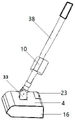
图中,1、清洁辊;1a、大清洁辊;1b、小清洁辊;2、清洁翅片;3、垃圾仓;4、机壳;5、防滴板;6、初级过滤网;7、储水空间;8、动力舱;9、驱动电机;10、电池盒;11、主链轮;12、链条;13、第一链轮;14、第二链轮;15、传动腔;16、腔盖;17、抽水泵;18、吸水管;19、送水管;20、车轮;21、紫外线灯;22、充电片组;23、舱盖;24、下刮板;25、上刮板;26、封门;27、永磁铁;28、铁片;29、抽屉;30、硅胶柱;31、接水槽;32、加热丝;33、轴架;34、刷毛;35、污水箱;36、负压风机;37、导向管;38、操纵杆;39、框架;40、支撑轴;41、插槽;42、运输辊;43、进污区域。In the figure, 1, cleaning roller; 1a, large cleaning roller; 1b, small cleaning roller; 2, cleaning fins; 3, garbage bin; 4, casing; 5, anti-drip plate; 6, primary filter; 7, Water storage space; 8. Power cabin; 9. Drive motor; 10. Battery box; 11. Main sprocket; 12. Chain; 13. First sprocket; 14. Second sprocket; 15. Transmission cavity; 16. Cavity cover; 17, water pump; 18, suction pipe; 19, water supply pipe; 20, wheel; 21, ultraviolet lamp; 22, charging sheet group; 23, hatch cover; 24, lower scraper; 25, upper scraper; 26, door sealing; 27, permanent magnet; 28, iron sheet; 29, drawer; 30, silica gel column; 31, sink; 32, heating wire; 33, axle frame; 34, bristles; 35, sewage tank; 36, negative Compressor; 37, guide pipe; 38, joystick; 39, frame; 40, support shaft; 41, slot; 42, transport roller; 43, dirt inlet area.
具体实施方式Detailed ways
下面结合附图和具体实施方式对本发明作进一步详细的说明。The present invention will be described in further detail below with reference to the accompanying drawings and specific embodiments.
如图1-28所示,一种双辊扫地设备,包括清扫组件、为清扫组件提供动力的动力及传动单元、垃圾仓3、用于封装垃圾仓3、动力及传动单元和清扫组件的机壳4、以及与机壳4转动连接的操纵杆38;清扫组件包括两个清洁辊1,两个清洁辊1旋转方向相反,每个清洁辊1均具有周向分布的清洁翅片2;两个清洁辊1各自的清洁翅片2与工作面三者之间形成的进污区域43的大小与工作环境适配;垃圾仓3入口与清扫组件的出污区域盛接配合;两个清洁辊1在工作状态下,至少有一个清洁辊1的清洁翅片2在工作面上形成的有效刮距具有连续性。所述清扫组件安装于机壳4前部,前侧的清洁辊1直径大于后侧的清洁辊1直径,前侧的清洁辊1为大清洁辊1a,后侧的清洁辊1为小清洁辊1b。清扫组件配合设置有刮污装置;所述的刮污装置包括用于刮除小清洁辊1b上脏污的下刮板24,下刮板24的刮污端清洁小清洁辊1b,垃圾仓3入口与下刮板24的脏污脱落端盛接配合。垃圾仓3内的底部安装有初级过滤网6;初级过滤网6与垃圾仓3内底端之间的空间为储水空间7。还包括集水装置;集水装置包括抽水泵17和污水箱35;抽水泵17抽取储水空间7内的水;抽水泵17的出水端通过送水管19污水箱35连通。垃圾仓3和机壳4为一体结构,垃圾仓3的排污端配合安装有封门26。封门26通过磁吸与垃圾仓3排污端密封连接。垃圾仓3为抽屉29,抽屉29与机壳4滑动连接。垃圾仓3靠近小清洁辊1b的端部设置有防滴板5,防滴板5下端与小清洁辊1b盛接配合。清洁辊1为向中部运输的螺旋状,清洁翅片2从两侧向中部螺旋。As shown in Figure 1-28, a double-roller sweeping equipment includes a sweeping assembly, a power and transmission unit for powering the sweeping assembly, a
本发明在使用时,根据实际使用需求进行取舍,可进行多种组合方式使用,并不限制于本说明书所述的实施例顺序或组合。机壳4可根据实际使用选择设置适配的形状,本领域技术人员可以实现。驱动电机9、抽水泵17、紫外线灯21等,所需电能均可由电池连接供给。所使用的逆时针或顺时针方向描述,以从机壳4左侧观察为准,传动腔15所在方位为左侧(并不限制传动腔15在左侧,仅用于举例描述)。所使用的前后左右等方向描述,以及所述实施例,均为便于描述理解,并不应限制本发明的保护范围。When the present invention is used, it can be selected according to actual use requirements, and can be used in various combinations, and is not limited to the order or combination of the embodiments described in this specification. The
附图1,主要原理解释,以具有清洁翅片2的清洁辊1为例(图示中大清洁辊1a位于小清洁辊1b前方),两个清洁辊1并排相接安装在机壳4前侧,地面等需要清洁的平面即为工作面,清扫组件的进污端即两个清洁辊1进垃圾的一侧,一般为与地面接触的一侧,出污区域为出垃圾的一侧,即两个清洁辊1脱离互相接触的一侧,两个清洁辊1与工作面三者之间形成的类似三角的区域为进污区域43。主要实现扫地功能,同时具有一定的拖地收水能力,提高了清扫体验,此处特意强调该性质。两个清洁辊1逆向转动,在中间接触的位置,运动方向向上方,形成向上运动的对夹。扫垃圾时,触碰到地面垃圾后,清洁翅片2可发生弯曲或压缩,刮地清洁,并最终携带垃圾,向前侧移动主要依靠从前侧的清洁辊1进垃圾,前侧为主要垃圾进口,由于机壳4底端离地一定的高度,则小于该高度的小垃圾可从机壳4底端通过,则在向后侧移动时,小垃圾可从后侧的清洁辊1进入到清扫组件中;同时具有拖地收水功能,地面有水时,在圆周转动过程中,在拖地行进方向指向的那一侧,清洁翅片2首先开始触地时与地面形成锐角则刮地效果较好,此时不易出现跳动、卡顿等问题,因此,逆时针转动的清洁辊1,向后方移动刮地效果好,顺时针转动的清洁辊1,向前方移动刮地效果好。且在单个清洁翅片2从触地开始到转动离开地面之间,存在有效刮距(不同硬度、不同形状、不同长度的清洁翅片2或其他类型的清洁辊1,所形成的有效刮距不同,可通过实验等方式测算,以测定清洁翅片2密度或角度间隔等),有效刮距即刮地效果较好(刮地干净)的区间,刮地效果较好还需要保证连续有效的刮地,即清洁辊1的清洁翅片2的有效刮距存在连续性(可重叠),保证刮地刮干净的连续性,避免出现未刮干净或未刮到的条状水痕残留印记。1, the main principle is explained, taking the cleaning roller 1 with
实施例一,附图2,包括一个清扫组件,且清扫组件安装在机壳4前部,垃圾仓3位于后部,清扫组件包括两个清洁辊1,且前侧清洁辊1直径大于后侧清洁辊1直径,依靠两个清洁辊1拾取垃圾和脏水。Embodiment 1, Figure 2, includes a cleaning assembly, and the cleaning assembly is installed at the front of the
如图3所示,动力及传动单元包括传动装置、驱动电机9、电池,传动装置包括与驱动电机9输出端连接的主链轮11,大清洁辊1a端部配合连接的第一链轮13、小清洁辊1b端部配合连接的第二链轮14,主链轮11通过链条12与第一链轮13和第二链轮14传动,且大清洁辊1a和小清洁辊1b逆向转动。机壳4左侧可设置传动腔15,并配合安装腔盖16,传动装置设置在传动腔15内,传动腔15配合安装腔盖16(传动装置可为一个独立组件,配合安装在机壳4上)。传动装置除所述链条12链轮传动外,还可以是双面皮带轮传动、纯齿轮传动、皮带轮皮带传动配合齿轮传动、链条12链轮配合齿轮传动、蜗轮蜗杆传动等。本实施例中,驱动电机9可安装在动力舱8内,动力舱8可位于垃圾仓3后部上端(动力舱8位置不限于垃圾仓3后部上端,可设置在垃圾仓3或机壳4内适合的位置,比如垃圾仓3前部上端靠近清扫组件位置,或者垃圾仓3部下端)。附图4,驱动电机9也可设置在机壳4的左侧或右侧,驱动电机9输出端直接与单个清洁辊1连接传动,依靠常规的动力传动设备带动同组另一个清洁辊1逆向转动;驱动电机9还可安装在机壳4内部的左侧,驱动电机9套接配合设置在清洁辊1的轴心位置,位于清洁辊1内部,驱动电机9的输出端与清洁辊1连接,节省左右方向空间占位,当需要向外侧输出动力时,比如带动另一个清洁辊1转动,可设置双轴驱动电机9,驱动电机9输出端的一端与套接设置的清洁辊1连接,另一端可与传动装置连接带动另一个清洁辊1转动,其他实施例也适用此种驱动电机9安装方式。动力及传动单元也可不依靠电能实现,比如通过使用者推动机壳4行进时,车轮20的转动形成动力,然后经过传动装置带动清扫组件转动,且两个清洁辊1逆向转动。As shown in Figure 3, the power and transmission unit includes a transmission device, a drive motor 9, and a battery. The transmission device includes a
两个清洁辊1均安装在机壳4前部,且一前一后安装,在二者的中间位置,二者的清洁翅片2相互挤压,形成交错挤压区域,二者下侧均接触地面且与地面挤压,大清洁辊1a逆时针转动,小清洁辊1b顺时针转动,均由动力及传动单元提供动力带动转动,依靠链条12同时进行传动,第一链轮13在链条12的内侧,第二链轮14在外侧,分别与链条12啮合传动,则两个清洁辊1转向相反。在向前推动和向后拉动的过程中,均可同时实现扫和拖的功能,扫地功能依靠两个清洁辊1夹取实现,拖地收水功能,在前进时,主要依靠后侧顺时针转动的清洁辊1实现,在向后时,主要依靠前侧逆时针转动的清洁辊1实现,借助水在地面的润湿等,将地面沾附垃圾从地面上清除下来(此处特意强调,可清除一般性沾附的垃圾,比如泥土等,对于胶粘垃圾等清理效果差,不在拖地扫地功能清除效果考虑内)。对于垃圾和水的拾取功能,依靠两个清洁辊1的携带和夹取,清洁辊1的清洁翅片2在转动过程中可利用表面携带一些垃圾和脏水,二者中间(即交错挤压区域)的下部存在三角区域(清扫组件中可通过调节设置清洁辊1参数,调节三角区域大小,比如二者的直径以及中心距、二者进污端与工作面下压接触程度),圆周转动的清洁翅片2无法触及的地方,对于一些较小的垃圾,无法同时受到两个清洁辊1的挤压夹取,此时主要依靠两种情况进行拾取,一是转动的清洁翅片2自身具有一定的携带力,垃圾和水会贴在清洁翅片2上,二是在持续转动的清洁翅片2拨动下,垃圾和水会被击飞或发生翘头等,使其能够被抬升夹取,尤其是清洁翅片2从地面上刮过后,脱离地面的瞬间,清洁翅片2末端产生一定的弹射加速效果,清洁翅片2的末端为远离轴心的一端,同理,垃圾和水在两个清洁辊1之间不断击飞传递,两个清洁辊1之间互不接触,也能实现清扫拾取垃圾和水的功能。清扫组件中可通过调节设置两个清洁辊1参数,调节进污区域43大小,比如二者的直径以及中心距、二者进污端与工作面下压接触程度以及转轴距地高度等参数,使进污区域43的大小适配所对应的工作环境,比如当主要拾取的垃圾或废弃物体积较大时(比如说类似于乒乓球类的垃圾拾取),则进污区域43的大小要与之适配,更好的实现夹取,避免进污区域43太小,待拾取物无法进入,或者进污区域43太大,待拾取物不容易被夹取或击飞拾取。适配时,并非要求形状必须相同,且可考虑清洁辊1为胶辊时,清洁翅片2具有变形能力,实际可夹取物品可略大于静态下所展示的进污区域43大小,同时考虑两个清洁辊1的中心距,具体参数的选择和进污区域43大小的适配可根据实验测定。The two cleaning rollers 1 are installed on the front of the
清洁辊1携带垃圾或水后,在机壳4内又实现分离,实现清洁辊1的自清洁,可依靠旋转的离心力以及两个清洁翅片2挤压转动时最后对物体的弹性抛出动作,两个清洁辊1在中间相互挤压,在经过挤压阶段后,清洁翅片2会有弹性释放以及前后两侧的清洁翅片2对物体产生的推力合力,均有助于抛出物体实现分离,两个清洁辊1不同的直径大小,不同的中心距,则交错挤压区域不同,最后的抛物角度也不同,后侧的清洁辊1直径小于前侧的清洁辊1时,抛物角度指向后上方,也造成了后侧的清洁辊1在上侧区域承载运输更多的垃圾和水(此处即为下述的可去除上刮板25结构的原因之一,可精简结构并降低阻力)。垃圾仓3盛接垃圾和水,垃圾仓3的前端可接近或压入小清洁辊1b的后侧,减少垃圾和水跟随清洁辊1继续转动。After the cleaning roller 1 carries garbage or water, it is separated again in the
附图5,本实施例还可增加防滴板5,防滴板5设置在小清洁辊1b后方,防滴板5主要盛接小清洁辊1b后侧甩出的水滴且未被垃圾仓3盛接收集的部分,或者从垃圾仓3前端漫出来的水滴,防滴板5的增加可进一步提高小清洁辊1b后侧不滴水不残留的效果。如图6所示,防滴板5可倾斜设置,防滴板5可安装在机壳4上,也可安装在垃圾仓3前部。防滴板5下端与小清洁辊1b的清洁翅片2末端可接触也可不接触,以水滴能够被清洁翅片2带走为准。当防滴板5与清洁翅片2末端接触时,防滴板5上盛接的少量水滴,能够再次被清洁翅片2末端携带且不掉落即可,或者再次被清洁翅片2扫拖弹射至有效刮距内或者其前侧的清洁翅片2上也可,防滴板5也可水平设置且与小清洁辊1b接触,如图6所示。5 , in this embodiment, an anti-drip plate 5 can also be added. The anti-drip plate 5 is arranged behind the
附图7,本实施例中,清洁辊1上分离出垃圾和水,还可依靠刮污装置,即增加下刮板24,和小清洁辊1b的清洁翅片2相切接触或压迫,进行硬性的刮离,同时清洁翅片2撞击在下刮板24的刮污端,可触发清洁翅片2末端的抖动或弹射,有助于从清洁翅片2上分离出垃圾和水,最后垃圾和水从下刮板24的脱落端掉入到垃圾仓3内,垃圾仓3前端可盛接小清洁辊1b甩出的水滴以及下刮板24脱落端流下的脏污。同理,机壳4内还可增加安装上刮板25,上刮板25用于清洁大清洁辊1a,,上刮板24和下刮板25均可作为刮污装置。7, in this embodiment, the garbage and water are separated from the cleaning roller 1, which can also be carried out by means of a scraping device, that is, adding a
上刮板25和下刮板24分别安装在机壳4内前部的上下两侧,分别对大清洁辊1a和小清洁辊1b实现清洁辊1的自清洁,可根据实际自清洁效果,选择性安装上刮板25和下刮板24,选择调节上刮板25或下刮板24二者分别和清洁翅片2关系为配合间距、或切线位置接触或压迫接触,压迫接触的程度即在清洁辊1转动的圆周体中,上刮板25或下刮板24所压入的最大深度(比如在清扫较大垃圾的使用环境中,下刮板24刮污端可与小清洁辊1b的清洁翅片2末端具有一定的间距,减少二者的撞击和摩擦,同时又能阻挡分离出较大的垃圾,垃圾大小的判断需考虑整体的形状)。自清洁的目的在于分离出垃圾和脏水后,清洁翅片2被刮除脏污的部分能够较为干净,然后与地面接触则可极少携带脏水,且基本不携带垃圾,保证其能够持续长时间扫地使用。本实施例中,上刮板25可竖直设置并且位于大清洁辊1a后侧竖向相切位置,下刮板24可从小清洁辊1b上方偏后位置压入小清洁辊1b2毫米左右。The
本实施例中还可增加初级过滤网6,与垃圾仓3底部形成储水空间7,提高刮地收水的体验,此时储水空间7即可为接水装置。In this embodiment, a
附图8-图9,本实施例中,垃圾仓3可与机壳4一体设置,垃圾仓3后端开口且安装封门26。垃圾仓3后端的开口转动安装封门26,垃圾仓3后端开口的下侧可设置永磁铁27,封门26下侧对应设置铁片28,通过磁吸关闭封门26且具有密封效果,可通过胶圈等提高密闭性,便于垃圾仓3存储较多垃圾,同时便于垃圾仓3竖立起来后,开口朝下,打开封门26倾倒垃圾。封门26也可依靠扭簧或者门栓或者卡接等形式配合垃圾仓3出口端。8-9, in this embodiment, the
实施例二,附图10,区别于实施例一种封门26结构,本实施例中垃圾仓3也可为抽屉29结构,抽屉29式的垃圾仓3与机壳4滑动连接,当需要倒垃圾时,将抽屉29取出倾倒即可,抽屉29内底部可设置初级过滤网6实现初级过滤。同时可推出,将抽屉29设置在垃圾仓3右侧的结构,附图11,抽屉29的结构设置需要考虑是否设置动力舱8等,对于动力舱8等占位需要进行避让,同时,可在抽屉29上设置硅胶柱30等,硅胶柱30固定于抽屉29上侧,位于动力舱8前侧,可拦截抛向动力舱8外侧壁的垃圾,抽屉29取出时对动力舱8外表面进行清洁。当设置抽屉29结构时,上刮板25或下刮板24也可与抽屉29为一体结构,抽屉29与机壳4采用卡接等对接定位稳定的连接结构。The second embodiment, Fig. 10, is different from the structure of the
实施例三,附图12,在实施例一的基础上,考虑提高刮水收水的实用性,还可增加抽水泵17,提高集水功能,设置抽水泵17,并安装在动力舱8右侧(抽水泵17也可为潜水泵结构,进水端直接安装在储水空间7内),从储水空间7吸水,增加污水箱35,可将脏水收集泵入污水箱35,污水箱35可挂设或插接在操纵杆38上,同时污水箱35与送水管19插接连通,当地面上水较多时,污水箱35满后,可拆卸迅速倒出。送水管19可从操纵杆38内部设置,从操纵杆38侧壁伸出,直接与污水箱35插接连通,便于从污水箱35上侧高位进水,送水管19也可与污水箱35下端插接连通,依靠密封胶圈以及单向阀式的插接连通结构即可。
本实施例还可在机壳4前端设置接水槽31,用于盛接大清洁辊1a向机壳4甩出的水,避免在集水时从前侧滴水,考虑水量较少,则可只设置接水槽31,也可在机壳4侧壁设置引流槽,将接水槽31内的水引向垃圾仓3。In this embodiment, a water receiving groove 31 can also be provided at the front end of the
本实施例中,附图13-图14,电池以及电池的充电接口的设置,电池可安装于电池盒10内,电池盒10可安装于操纵杆38上,充电接口为充电片组22,可设置于机壳4侧壁或者操纵杆38上,或者设置于电池盒10上,接口形式为现有常规技术手段。电池还可为柱状结构,操纵杆38内部中空,将电池设置于操纵杆38内部。除采用电池供电外,还可以利用外界电源进行供电。In this embodiment, Figures 13 to 14 show the setting of the battery and the charging interface of the battery. The battery can be installed in the
操纵杆38上端可设置操纵手柄,操纵手柄上可设置控制开关,控制开关用于开启驱动电机9或抽水泵17。The upper end of the
本实施例中,附图15,可增加垃圾仓3底端的紫外线灯21,可起到一定的杀菌消毒作用。紫外线灯21可单独控制,或者同步于驱动电机9工作。In this embodiment, as shown in FIG. 15 , an
本实施例中,附图16,可增加加热丝32的设置,加热丝32可与电池相连,当清洁辊1上缠绕头发丝或线圈等时,控制加热丝32通电升温,将头发丝或线圈等烧断,则可有利于在持续的转动过程中将扫入垃圾仓3内。加热丝32可固定设置在机壳4内与清洁翅片2接触或接近的位置。比如机壳4前侧设置单个清扫组件时,机壳4内前部设置一条电热丝,接近前侧清洁辊1的清洁翅片2而不接触,垃圾仓3前端下部可设置电热丝,接近后侧清洁辊1的清洁翅片2而不接触,避免弹射或敲击损坏,沿左右方向设置分布,覆盖清洁辊1轴向长度,通过热量烤断头发丝、毛线等。鉴于头发丝等对轴端及轴承等影响较大,可将加热丝32设置在主轴轴端与轴承连接的位置。电热丝也可依靠外界电源供电,比如在充电时可启动电热丝,可单独设置电热丝的开关,减少对电池电量的使用。In this embodiment, as shown in FIG. 16 , the setting of the
实施例四,附图17,可包括一个清扫组件,且清扫组件安装在机壳4中部,清扫组件包括两个清洁辊1,两个清洁辊1直径相同,清扫组件的前后两侧均可为垃圾仓3。此时清扫组件抛物角度向上,可设置“V”字形的导向板,将垃圾和水引导至两侧的垃圾仓3。同理,通过适当形状的导向板设置,两个直径相同的清洁辊1设置在机壳4前端,一个垃圾仓3在后,导向板将垃圾导向后侧,也可实现。
两个清洁辊1均安装在机壳4前部,且前侧清洁辊1直径大于后侧清洁辊1直径,使用体验较佳。对于将两个清洁辊1安装在机壳4中间位置,或者两个清洁辊1分别安装在机壳4前后两侧等安装形式,以及清洁辊1直径大小配合关系,均可根据描述的工作原理和需求等进行适配,为可知的变形。The two cleaning rollers 1 are installed at the front of the
本实施例其他设置可参考其他实施例,根据位置和实际需求适配。For other settings in this embodiment, refer to other embodiments, and adapt according to the location and actual needs.
实施例五,附图18,上述实施例中包括一个清扫组件,可前后对称设置两个清扫组件,每个清扫组件包括两个清洁辊1,两个清扫组件分别安装在垃圾仓3的前后两侧,前后两个清扫组件对称设置,前侧的清扫组件中,前侧的清洁辊1逆时针转动,后侧的清扫组件顺时针转动。清扫组件转动安装于机壳4上。垃圾仓3前后两侧均为进口,靠近垃圾仓3进口的清洁辊1的直径小于另一个清洁辊1的直径,使抛物角度直接指向垃圾仓3。至于安装数量更多的清扫组件,可根据本文描述进行相关设置。Embodiment 5, Fig. 18, the above-mentioned embodiment includes one cleaning assembly, two cleaning assemblies can be arranged symmetrically in the front and rear, each cleaning assembly includes two cleaning rollers 1, and the two cleaning assemblies are installed on the front and rear of the
动力及传动单元的驱动电机9可设置在垃圾仓3上部,通过传动装置进行动力传递,具体传动方式包括但不限于齿轮传递、链条12传递,使每个清扫组件出污端均向垃圾仓3方向卷入;The drive motor 9 of the power and transmission unit can be arranged on the upper part of the
综上。清洁辊1材质可为硅胶、橡胶、热塑性弹性体等,易干易清洁。清洁辊1为具有清洁翅片2的结构,也可为其他结构,比如附图19,清洁辊1具有清洁翅片2和刷毛34,刷毛34可为硅胶、橡胶、玻璃纤维、塑料等材质。同时,小清洁辊1b还可选用常规的布辊,配合大清洁辊1a使用。To sum up. The cleaning roller 1 can be made of silicone, rubber, thermoplastic elastomer, etc., which is easy to dry and clean. The cleaning roller 1 has a structure with cleaning
附图20,清洁辊1与机壳4左右两侧转动连接,可采用插接快装结构进行安装。清洁辊1的主轴右端轴心位置设置插孔,机壳4右侧壁设置定轴孔,定轴孔内插接或螺旋连接固定一个支撑轴40,支撑抽左部与主轴的插孔插接且转动配合;主轴左端与链轮插接连接且同步转动,可依靠交错插接的形式或者键槽、花键等形式实现插接连接,便于安装。20, the cleaning roller 1 is connected with the left and right sides of the
具有清洁翅片2的清洁辊1可一体成型,也可采用插接等形式,将清洁翅片2插装至清洁辊1上。清洁翅片2的竖向截面可为弧形或直线型等,清洁翅片2较长,且在一定硬度范围内可弯曲形变,在主轴抖动和上下浮动较小的情况下即可清扫较大的垃圾,同时有效刮地区间较大,便于实现有效刮地的连续性(若清洁翅片2较短,则可采用主轴抖动或者上下浮动的形式提高可收集垃圾体积大小,但是会造成结构复杂易损的问题)。清洁翅片2可沿清洁辊1圆周方向均匀分布,便于实现有效刮地的连续性。The cleaning roller 1 with the
较佳实施例1:单个清扫组件安装在机壳4前侧,清扫组件包括两个清洁辊1即可,附图21所示,可不设置初级过滤网6以及上刮板25。Preferred Embodiment 1: A single cleaning component is installed on the front side of the
附图22、附图23所示,清洁辊1可为整体螺旋状,单向螺旋(图22)或者从两端向中部螺旋(图23B所示)。清洁辊1为向中部运输的螺旋状时,转动时螺旋状具有运输性,以后侧清洁辊1为例,从两端向中部螺旋(一侧螺旋方向为顺时针,另一侧为逆时针,向中部引导,在中部可为连接形态),在顺时针转动时,对工作面上的水具有运输作用,且向中部运输,避免脏水流向两端外侧,同时仍能产生刮水和拾水的功能,水最终仍被拾取到垃圾仓3内。本实施例中,清扫组件中,前侧可选用直辊(如图23A所示),即清洁翅片2与轴向方向平行,后侧可选用向中部运输的螺旋辊(如图23B所示),即清洁翅片2从两侧向中部螺旋,向中部运输。相对于直辊,螺旋状的清洁辊1配合直板形的下刮板24,即可起到缓冲接触的作用,降低噪音。从螺旋转动与下刮板24的接触形式,可推得,清洁辊1采用直辊时,下刮板24采用螺旋线形或端部倾斜等,也可起到缓冲接触的作用。As shown in FIG. 22 and FIG. 23 , the cleaning roller 1 can be a whole helical shape, a one-way helical (FIG. 22) or a helical from both ends to the middle (FIG. 23B). When the cleaning roller 1 is in a spiral shape that is transported to the middle, the spiral shape has transportability when it rotates. Take the rear cleaning roller 1 as an example, spiral from both ends to the middle (one side is clockwise, the other side is counterclockwise, Guide to the middle, and can be connected in the middle), when it rotates clockwise, it has a transport effect on the water on the working surface, and it is transported to the middle to prevent dirty water from flowing to the outside of both ends, while still producing wipes and water pickups function, the water is eventually picked up into the
下刮板24可从上侧压迫小清洁辊1b两毫米左右。The
附图24,增加一个运输辊42用于运输垃圾,运输辊42可为清洁辊1结构,两个清洁辊1和一个运输辊42成三角分布,运输辊42在小清洁辊1b上侧,运输辊42可对大清洁辊1a进行清洁(二者也可不接触),同时与小清洁辊1b逆向转动,实现运输功能,将垃圾向后侧抛,运输辊42可与小清洁辊1b接触,也可与下刮板24上侧接触,以便于向后方运输垃圾。运输辊42为清洁辊1结构时,运输辊42的清洁翅片2可为两个,也可为一个翅片,也可为其他结构,比如毛刷结构等,或者为框架39结构,附图,中部为空,或者只有一半的框架39,左右两端分别与机壳4转动连接,减少对垃圾的阻挡;24, a
可以通过小清洁辊1b的倒转实现下刮板24挂垃圾的清理,大清洁辊1a可同步于小清洁辊1b倒转。The cleaning of the rubbish hanging on the
较佳实施例2:带有集水功能的方案:附图12,在较佳实施例1的基础上,增加设置防滴板5、初级过滤网6、收水水路、抽水泵17和污水箱35等,操纵杆38利用轴架33进行连接,送水管19可从操纵杆38内部穿过,并从侧壁伸出,可与污水箱35插接连通,污水箱35顶端可设置排气排水口。控制开关可设置为两个,分别控制驱动电机9进行扫地功能,有较多水时,控制抽水泵17进行抽水。附图26,还可以将动力舱8设置在垃圾仓3上侧中部,污水箱35设置在垃圾仓3上部后端,位于动力舱8后侧。Preferred Embodiment 2: Scheme with water collection function: Figure 12, on the basis of preferred embodiment 1, additionally set up anti-drip plate 5,
附图27,本实施例中,不设置接水槽31,使机壳4前端位于大清洁辊1a上侧,且不与大清洁辊1a的清洁翅片2接触,机壳4前端可与大清洁辊1a最前端相距三毫米左右。若地面上存在水,且大清洁辊1a将少量水甩向上方的机壳4后,水顺机壳4向下滑并从机壳4前端聚集,随后滴落时可落在大清洁辊1a上。不与清洁辊1接触,有利于清洁辊1倒转。27, in this embodiment, the water receiving groove 31 is not provided, so that the front end of the
较佳实施例3:以大型设备为例,附图28,进行区域清扫。携带较大的垃圾仓3,垃圾仓3可配合设置负压系统,清扫组件拾取垃圾后,利用负压系统收集垃圾,或者是运输装置运输垃圾,以更好的利用较高的垃圾仓3。Preferred Embodiment 3: Take large equipment as an example, as shown in Figure 28, to perform area cleaning. Carry a
垃圾仓3上端安装负压风机36,负压风机36的抽风端与垃圾仓3内部连通,垃圾仓3的进污端与清扫组件的出污端对接,可由导向管37进行连接,导向管37下端进口与清扫组件出污区域对接,导向管37上端延伸至垃圾仓3内上部,直接由负压形成运输垃圾的动力。A
Claims (10)
Priority Applications (1)
| Application Number | Priority Date | Filing Date | Title |
|---|---|---|---|
| CN202011555246.7A CN114668337A (en) | 2020-12-24 | 2020-12-24 | A double-roller sweeping device |
Applications Claiming Priority (1)
| Application Number | Priority Date | Filing Date | Title |
|---|---|---|---|
| CN202011555246.7A CN114668337A (en) | 2020-12-24 | 2020-12-24 | A double-roller sweeping device |
Publications (1)
| Publication Number | Publication Date |
|---|---|
| CN114668337A true CN114668337A (en) | 2022-06-28 |
Family
ID=82070965
Family Applications (1)
| Application Number | Title | Priority Date | Filing Date |
|---|---|---|---|
| CN202011555246.7A Pending CN114668337A (en) | 2020-12-24 | 2020-12-24 | A double-roller sweeping device |
Country Status (1)
| Country | Link |
|---|---|
| CN (1) | CN114668337A (en) |
Cited By (2)
| Publication number | Priority date | Publication date | Assignee | Title |
|---|---|---|---|---|
| CN115137268A (en) * | 2022-08-04 | 2022-10-04 | 深圳市杉川机器人有限公司 | Cleaning assembly and cleaning device |
| CN117722058A (en) * | 2023-12-19 | 2024-03-19 | 四川旅发环保科技有限公司 | A self-cleaning toilet |
Citations (8)
| Publication number | Priority date | Publication date | Assignee | Title |
|---|---|---|---|---|
| EP0595007A1 (en) * | 1992-10-24 | 1994-05-04 | Alfred Kärcher GmbH & Co. | Floor cleaning device |
| JP2002233485A (en) * | 2001-02-09 | 2002-08-20 | Casle Kk | Hand-push type cleaner |
| JP2006346293A (en) * | 2005-06-17 | 2006-12-28 | Kao Corp | Cleaning tool |
| CN201404161Y (en) * | 2009-03-20 | 2010-02-17 | 杨阳 | A floor cleaning machine |
| DE102014102812A1 (en) * | 2014-03-04 | 2015-09-10 | Alfred Kärcher Gmbh & Co. Kg | Sweeper and method for operating a sweeper |
| CN205391068U (en) * | 2016-01-19 | 2016-07-27 | 郑子繁 | Washing recovery unit of clean machinery |
| CN111466841A (en) * | 2020-04-30 | 2020-07-31 | 江苏美的清洁电器股份有限公司 | Roller device and cleaning equipment |
| CN211299790U (en) * | 2019-09-27 | 2020-08-21 | 深圳市银星智能科技股份有限公司 | Separation storage device and cleaning robot |
-
2020
- 2020-12-24 CN CN202011555246.7A patent/CN114668337A/en active Pending
Patent Citations (8)
| Publication number | Priority date | Publication date | Assignee | Title |
|---|---|---|---|---|
| EP0595007A1 (en) * | 1992-10-24 | 1994-05-04 | Alfred Kärcher GmbH & Co. | Floor cleaning device |
| JP2002233485A (en) * | 2001-02-09 | 2002-08-20 | Casle Kk | Hand-push type cleaner |
| JP2006346293A (en) * | 2005-06-17 | 2006-12-28 | Kao Corp | Cleaning tool |
| CN201404161Y (en) * | 2009-03-20 | 2010-02-17 | 杨阳 | A floor cleaning machine |
| DE102014102812A1 (en) * | 2014-03-04 | 2015-09-10 | Alfred Kärcher Gmbh & Co. Kg | Sweeper and method for operating a sweeper |
| CN205391068U (en) * | 2016-01-19 | 2016-07-27 | 郑子繁 | Washing recovery unit of clean machinery |
| CN211299790U (en) * | 2019-09-27 | 2020-08-21 | 深圳市银星智能科技股份有限公司 | Separation storage device and cleaning robot |
| CN111466841A (en) * | 2020-04-30 | 2020-07-31 | 江苏美的清洁电器股份有限公司 | Roller device and cleaning equipment |
Cited By (2)
| Publication number | Priority date | Publication date | Assignee | Title |
|---|---|---|---|---|
| CN115137268A (en) * | 2022-08-04 | 2022-10-04 | 深圳市杉川机器人有限公司 | Cleaning assembly and cleaning device |
| CN117722058A (en) * | 2023-12-19 | 2024-03-19 | 四川旅发环保科技有限公司 | A self-cleaning toilet |
Similar Documents
| Publication | Publication Date | Title |
|---|---|---|
| RU2573967C2 (en) | Vacuum cleaner | |
| CN112006614B (en) | An integrated station for intelligent cleaning robots | |
| CN100446710C (en) | Surface cleaning apparatus | |
| CN111938526B (en) | Integrated station of sweeping and dragging robot | |
| CN111973072A (en) | Sweeping and mopping cleaning robot's integrated station | |
| CN111920349B (en) | Integrated station of drag-and-suction robot | |
| CN110338716A (en) | Sweeping robot and its cleaning device | |
| CN112545394A (en) | Control method of cleaning robot system | |
| CN109907704A (en) | Hand-held type is dragged and is swept structure | |
| CN107007213A (en) | A kind of roller floor cleaning machine that self can be cleaned | |
| CN112535440B (en) | Cleaning robot with cleaning seat | |
| CN111973091B (en) | An integrated station for intelligent sweeping and mopping robots | |
| CN108742355B (en) | Indoor ground intelligent cleaning robot | |
| CN114668336A (en) | Sweeping and mopping integrated robot with two cleaning rollers and flushing base | |
| CN114668337A (en) | A double-roller sweeping device | |
| CN209172185U (en) | A kind of sliding door door track dust cleaning plant | |
| CN112806925A (en) | Clean power device and cleaning machine thereof | |
| CN217161964U (en) | Cleaning brush mechanism and cleaning equipment | |
| CN102715874A (en) | Floor cleaner | |
| CN1620983A (en) | Floor sweeping machine | |
| CN219089114U (en) | Floor brush structure and cleaning equipment | |
| CN100522038C (en) | Device for cleaning the ground | |
| CN2673276Y (en) | Indoor floor automatic sweeping machine | |
| CN215424444U (en) | Clean power device and cleaning machine thereof | |
| CN214433997U (en) | Integrated station and cleaning robot system thereof |
Legal Events
| Date | Code | Title | Description |
|---|---|---|---|
| PB01 | Publication | ||
| PB01 | Publication | ||
| SE01 | Entry into force of request for substantive examination | ||
| SE01 | Entry into force of request for substantive examination | ||
| RJ01 | Rejection of invention patent application after publication | ||
| RJ01 | Rejection of invention patent application after publication |
Application publication date: 20220628 |