CN114554646A - Bidirectional light source with signal line control - Google Patents
Bidirectional light source with signal line control Download PDFInfo
- Publication number
- CN114554646A CN114554646A CN202210291342.8A CN202210291342A CN114554646A CN 114554646 A CN114554646 A CN 114554646A CN 202210291342 A CN202210291342 A CN 202210291342A CN 114554646 A CN114554646 A CN 114554646A
- Authority
- CN
- China
- Prior art keywords
- signal
- module
- port
- signal line
- reverse current
- Prior art date
- Legal status (The legal status is an assumption and is not a legal conclusion. Google has not performed a legal analysis and makes no representation as to the accuracy of the status listed.)
- Pending
Links
- 230000002457 bidirectional effect Effects 0.000 title abstract description 7
- 230000000903 blocking effect Effects 0.000 claims description 25
- 230000002265 prevention Effects 0.000 claims description 11
- 230000003595 spectral effect Effects 0.000 abstract description 4
- 238000001228 spectrum Methods 0.000 description 6
- 230000000694 effects Effects 0.000 description 5
- 238000000034 method Methods 0.000 description 3
- 238000005034 decoration Methods 0.000 description 2
- 238000004519 manufacturing process Methods 0.000 description 2
- 239000011324 bead Substances 0.000 description 1
- 239000000969 carrier Substances 0.000 description 1
- 238000010586 diagram Methods 0.000 description 1
- 238000005516 engineering process Methods 0.000 description 1
- 238000005286 illumination Methods 0.000 description 1
- 238000004806 packaging method and process Methods 0.000 description 1
- 239000000843 powder Substances 0.000 description 1
Images


Classifications
-
- H—ELECTRICITY
- H05—ELECTRIC TECHNIQUES NOT OTHERWISE PROVIDED FOR
- H05B—ELECTRIC HEATING; ELECTRIC LIGHT SOURCES NOT OTHERWISE PROVIDED FOR; CIRCUIT ARRANGEMENTS FOR ELECTRIC LIGHT SOURCES, IN GENERAL
- H05B45/00—Circuit arrangements for operating light-emitting diodes [LED]
- H05B45/30—Driver circuits
-
- H—ELECTRICITY
- H05—ELECTRIC TECHNIQUES NOT OTHERWISE PROVIDED FOR
- H05B—ELECTRIC HEATING; ELECTRIC LIGHT SOURCES NOT OTHERWISE PROVIDED FOR; CIRCUIT ARRANGEMENTS FOR ELECTRIC LIGHT SOURCES, IN GENERAL
- H05B45/00—Circuit arrangements for operating light-emitting diodes [LED]
- H05B45/20—Controlling the colour of the light
-
- H—ELECTRICITY
- H05—ELECTRIC TECHNIQUES NOT OTHERWISE PROVIDED FOR
- H05B—ELECTRIC HEATING; ELECTRIC LIGHT SOURCES NOT OTHERWISE PROVIDED FOR; CIRCUIT ARRANGEMENTS FOR ELECTRIC LIGHT SOURCES, IN GENERAL
- H05B45/00—Circuit arrangements for operating light-emitting diodes [LED]
- H05B45/30—Driver circuits
- H05B45/32—Pulse-control circuits
-
- Y—GENERAL TAGGING OF NEW TECHNOLOGICAL DEVELOPMENTS; GENERAL TAGGING OF CROSS-SECTIONAL TECHNOLOGIES SPANNING OVER SEVERAL SECTIONS OF THE IPC; TECHNICAL SUBJECTS COVERED BY FORMER USPC CROSS-REFERENCE ART COLLECTIONS [XRACs] AND DIGESTS
- Y02—TECHNOLOGIES OR APPLICATIONS FOR MITIGATION OR ADAPTATION AGAINST CLIMATE CHANGE
- Y02B—CLIMATE CHANGE MITIGATION TECHNOLOGIES RELATED TO BUILDINGS, e.g. HOUSING, HOUSE APPLIANCES OR RELATED END-USER APPLICATIONS
- Y02B20/00—Energy efficient lighting technologies, e.g. halogen lamps or gas discharge lamps
- Y02B20/40—Control techniques providing energy savings, e.g. smart controller or presence detection
Landscapes
- Circuit Arrangement For Electric Light Sources In General (AREA)
- Led Devices (AREA)
Abstract
The invention discloses a bidirectional light source with signal line control, which comprises a signal line control light-emitting module and a reverse light-emitting module, wherein the signal line control light-emitting module and the reverse light-emitting module are connected in parallel to a first port of a power line and a second port of the power line of a light source; the signal line control light-emitting module comprises an LED color lamp group and an LED driver for driving the LED color lamp group according to a signal line signal; when the potential of the first port of the power line is higher than that of the second port of the power line, the LED driver drives the LED colored lamp group according to the signal line signal; and when the potential of the first port of the power line is lower than that of the second port of the power line, the reverse light-emitting module works. The invention solves the problem that the full-color control product cannot pass reverse current through signal line cascade, and the warm white system is added on the basis of RGB full-color control through the warm white system LED driven by the reverse current, and further a wider high-precision spectral range is obtained through duty ratio mixing of the warm white system and the RGB full-color system.
Description
Technical Field
The invention relates to the field of LED decorative lighting, in particular to a bidirectional light source with signal line control.
Background
The full-color control products are realized through signal line cascade in the market, are applied to scenes such as outdoor display in a large scale, and have already started to enter the household decoration and illumination market through the update of production technology at present. For example, chinese patent publication No. CN200983690 discloses a color control system with parallel LEDs, and for example, chinese patent publication No. CN214094084U discloses a point-control color LED string and a lamp.
The home decoration lighting market requires, on the one hand, color control effects and, on the other hand, also warm white series effects. At present, the common method is that a signal wire is cascaded to realize that a special control channel is added to a full-color control chip, and a four-channel control method comprising a warm white LED control channel is formed on the basis of three RGB control channels. According to the method, the warm white LED is manufactured by the blue LED point fluorescent powder during lamp bead packaging, so that the color temperature of the warm white LED is easy to deviate.
At present, the current of a signal wire cascade connection is unidirectional when a full-color control product is realized, the current can only flow from one fixed end to the other end, the reverse current is not allowed, the LED of the other color system can not be driven by the reverse current to realize the large-range spectrum effect, and particularly, the increase of warm white color is realized by allowing the reverse current on the basis of RGB.
Disclosure of Invention
The invention aims to provide a bidirectional light source with signal line control, which is characterized in that a warm white LED driven by reverse current is added with a warm white system on the basis of RGB full-color control, and further, the warm white LED and the RGB full-color LED are mixed in duty ratio to obtain wider high-precision spectral range.
A bi-directional light source with signal line control, the light source comprising:
the signal line control light-emitting module and the reverse light-emitting module are connected in parallel to a first power line port and a second power line port of the light source;
the signal line control light-emitting module comprises an LED color lamp group and an LED driver for driving the LED color lamp group according to a signal line signal;
when the electric potential of the first port of the power line is higher than that of the second port of the power line, the LED driver drives the LED color lamp group according to the signal line signal; and when the potential of the first port of the power line is lower than that of the second port of the power line, the reverse light-emitting module works.
The signal line control light-emitting module and the reverse light-emitting module can be packaged together, welded together through other carriers, and connected together through a plurality of lengths of wires. The reverse light-emitting module can be a single light-emitting diode, can also be a plurality of light-emitting diodes, and can also be a light-emitting module comprising a control module.
The LED driver includes: the reverse current blocking module and the signal decoding control module are connected with the signal processing module;
the input end of the reverse current blocking module is connected with the first port of the power line, the output end of the reverse current blocking module is connected with the power supply end of the signal decoding control module, and the signal decoding control module drives the LED color lamp set according to the signal of the signal line. It should be understood that the working current of a part of the circuits of the signal decoding control module may pass through the reverse current blocking module, or the working current of the whole circuits of the signal decoding control module may pass through the reverse current blocking module.
When the electric potential of the first port of the power line is higher than that of the second port of the power line, the signal decoding control module drives the LED color lamp group according to a signal of the signal line.
The signal line signal may be active in a high pulse, active in a low pulse, or active in a combination of a high pulse and a low pulse. Preferably, the time period T is given1A high pulse of (d) represents a logic 0, given a duration T2A high pulse of (a) represents a logic 1. As another embodiment, the duration T is given3Represents a logic 0 for a given duration T4A low pulse of (a) indicates a logic 1. Preferably, a logic 0 or a logic 1 may be represented by a combination of a high pulse of different given duration and a low pulse of different given duration. In another embodiment, the signal line signal may be a frequency-modulated signal of a voltage or a current.
Preferably, the signal line signal has a high pulse length of 0.5us and a low pulse length of 2.0us representing a logic 0, and a low pulse length of 0.5us and a high pulse length of 2.0us representing a logic 1.
The input end of the reverse current blocking module is connected with the first port of the power line, the output end of the reverse current blocking module is connected with the power supply end of the signal decoding control module, the ground of the signal decoding control module is connected with the level of the second port of the power line, and the signal decoding control module drives the LED color lamp set.
Preferably, the LED color lamp sets may be connected in common anode, the cathodes of the LEDs in the LED color lamp sets are respectively connected to the output of the signal decoding control module, the common anode of the LED color lamp sets may be connected to the output of the reverse current blocking module, and the common anode of the LED color lamp sets may also be connected to the input of the reverse current blocking module. In another embodiment, the LED color lamp sets may be connected with a common cathode, anodes of the LEDs in the LED color lamp sets are respectively connected with the output of the signal decoding control module, and the common cathode of the LED color lamp sets is connected with the second port of the power line.
The reverse current prevention module can be a single device or formed by combining a plurality of devices. The reverse current blocking means may be a resistor through which the reverse current is limited to a range of less than 500 ma.
Preferably, the reverse current blocking module is a unidirectional conductive module, the reverse current blocking module is turned on when the potential of the input end of the reverse current blocking module is higher than the potential of the output end of the reverse current blocking module, and the reverse current blocking module is turned off when the potential of the input end of the reverse current blocking module is lower than the potential of the output end of the reverse current blocking module.
Preferably, the unidirectional conductive module is a diode, an anode of the diode is connected with the first port of the power line, and a cathode of the diode is connected with the power supply end of the signal decoding control module; or the unidirectional conducting element is an equivalent diode formed by an NPN triode, a collector and a base of the NPN triode are connected and then connected with the first port of the power line, and an emitter is connected with the power supply end of the signal decoding control module; or the unidirectional conductive element is an equivalent diode formed by a PNP triode, a collector and a base of the PNP triode are connected and then connected with the power supply end of the signal decoding control module, and an emitter is connected with the first port of the power line.
Preferably, the reverse current prevention module and the signal decoding control module are integrated in the same integrated circuit; the integrated circuit is integrated in the same integrated circuit, so that the device cost can be reduced, and the production cost of products can be reduced. As another embodiment, the reverse current blocking module and the signal decoding control module are implemented by different independent modules, and may be implemented by a single chip or module.
Preferably, the reverse light emitting module is composed of a plurality of LEDs. Further, the number of the LEDs may be 1, or may be more than 1. The LEDs can be in a parallel structure, can be connected in parallel and then in series, and can also be connected in series and then in parallel. Preferably, the reverse light emitting module may be warm white.
It should be understood that the reverse light emitting module can be operated in a constant state operation mode, a controlled variable state operation mode, or a light emitting module with a wide spectrum range controlled by a signal line.
Preferably, the LED driver includes a signal output port, and the signal decoding control module decodes the received control signal of the LED driver from the signal line and outputs a remaining signal from the signal output port.
Preferably, the LED driver receives a data packet with N-bit logic codes from the signal line, wherein M-bit logic codes are used for controlling the LED color lamp set, and the remaining (M-N) -bit logic codes are output by the signal output port. It should be understood that N bits refer to several bits, and the corresponding value may be selected according to a desired application scenario or product. It should be appreciated that the LED driver may encode the data packets received from the signal line in a different manner than the LED driver output.
Preferably, the LED color lamp set comprises three primary color LEDs of red, green and blue.
The invention controls the light-emitting module and the reverse light-emitting module through the signal line, and a wide color spectrum effect is obtained through combination. Compared with the prior art, the light source provided by the invention can obtain a spectrum range by bidirectional power supply, driving the LED colored lamp set by a signal line signal through forward current, and then increasing another spectrum range in a reverse direction, so that a warm white system with high-precision color temperature can be obtained on the premise of not increasing the cost of the signal line control light-emitting module.
Drawings
FIG. 1 is a bi-directional light source with signal line control;
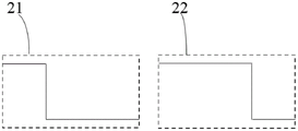
FIG. 2 is a schematic diagram of a signal line with a logic 0 and a logic 1;
fig. 3 shows ingress packets and egress packets.
Detailed Description
The invention will be described in further detail below with reference to the figures and specific embodiments.
As shown in fig. 1, a bidirectional light source 1 with signal line control of the present embodiment includes:
the signal line control light-emitting module 11 and the reverse light-emitting module 12 are connected in parallel at a first power line port 13 and a second power line port 14 of the light source;
the signal line control light-emitting module 11 comprises an LED colored lamp group 111 and an LED driver 112 for driving the LED colored lamp group 111 according to the signal of the signal line 15;
when the potential of the first power line port 13 is higher than that of the second power line port 14, the LED driver 112 drives the LED colored lamp group 111 according to the signal of the signal line 15; when the power line first port 13 is lower in potential than the power line second port 14, the reverse light-emitting module 12 operates.
The LED driver 112 includes: a reverse current prevention module 1121, a signal decoding control module 1122;
the input end of the reverse current blocking module 1121 is connected to the first port 13 of the power line, the output end of the reverse current blocking module 1121 is connected to the signal decoding control module 1122, and the signal decoding control module 1122 drives the LED color lamp set 111 according to the signal of the signal line 15.
The LED driver 112 of the present embodiment includes a signal output port 16, and the signal decoding control module 1122 decodes the received control signal of the LED driver from the signal line 15 and outputs the remaining signal from the output port 16.
The LED colored light set 111 of the present embodiment is connected by a common anode, the LED colored light set 111 includes a red LED 1111, a green LED 1112, and a blue LED 1113, cathodes of the red LED 1111, the green LED 1112, and the blue LED 1113 are respectively connected to the output of the electrical signal decoding control module 1122, and common anodes of the red LED 1111, the green LED 1112, and the blue LED 1113 are connected to an output terminal of the reverse current blocking module 1121.
In this embodiment, the reverse current blocking module 1121 is a diode, an anode of the diode is connected to the first port 13 of the power line, and a cathode of the diode is connected to the signal decoding control module 1122.
In the embodiment, as shown in fig. 2, the signal line 15 has a high pulse length of 0.5us and a low pulse length of 2.0us representing a logical 0(21), and a low pulse length of 0.5us and a high pulse length of 2.0us representing a logical 1 (22).
As shown in fig. 3, in the present embodiment, the LED driver 112 receives the 48-bit logically encoded input data packet 31 from the signal line 15, wherein the 24-bit logically encoded is used for controlling the LED color lamp set 111, and the remaining 24-bit logically encoded is output as the output data packet 32 from the signal output port 16. It should be understood that the number of data bits received by the LED driver 112 may be dynamically varied, and the corresponding value may be selected according to the desired application scenario or product.
The invention controls the light-emitting module and the reverse light-emitting module through the signal line, and a wide color spectrum effect is obtained by combination. Compared with the prior art, the light source of the invention can obtain a warm white system with high-precision color temperature by supplying power bidirectionally, driving the LED colored lamp set by a forward current and a signal line signal to obtain a spectral range and increasing another spectral range reversely on the premise of not increasing the cost of the signal line control light-emitting module.
Claims (8)
1. A bi-directional light source with signal line control, said light source comprising:
the signal line control light-emitting module and the reverse light-emitting module are connected in parallel to a first power line port and a second power line port of the light source;
the signal line control light-emitting module comprises an LED color lamp group and an LED driver for driving the LED color lamp group according to a signal line signal;
when the electric potential of the first port of the power line is higher than that of the second port of the power line, the LED driver drives the LED color lamp group according to the signal line signal; and when the potential of the first port of the power line is lower than that of the second port of the power line, the reverse light-emitting module works.
2. The bi-directional light source with signal line control of claim 1, wherein said LED driver comprises,
the reverse current blocking module and the signal decoding control module are connected with the signal processing module;
the input end of the reverse current blocking module is connected with the first port of the power line, the output end of the reverse current blocking module is connected with the power supply end of the signal decoding control module, and the signal decoding control module drives the LED color lamp set according to the signal of the signal line.
3. The bi-directional light source with signal line control of claim 2, wherein said reverse current prevention module is a unidirectional conducting module, said reverse current prevention module being turned on when an input terminal of said reverse current prevention module is at a higher potential than an output terminal of said reverse current prevention module, said reverse current prevention module being turned off when an input terminal of said reverse current prevention module is at a lower potential than an output terminal of said reverse current prevention module.
4. The bi-directional light source with signal line control of claim 3, wherein said unidirectional conducting module is a diode, said diode having an anode connected to said power line first port and a cathode connected to said signal decoding control module power supply terminal; or the unidirectional conducting element is an equivalent diode formed by an NPN triode, a collector and a base of the NPN triode are connected and then connected with the first port of the power line, and an emitter is connected with the power supply end of the signal decoding control module; or the unidirectional conductive element is an equivalent diode formed by a PNP triode, a collector and a base of the PNP triode are connected and then connected with the power supply end of the signal decoding control module, and an emitter is connected with the first port of the power line.
5. The bi-directional light source with signal line control of claim 4, wherein said reverse current prevention module and said signal decode control module are integrated in the same integrated circuit.
6. The bi-directional light source with signal line control of claim 5, wherein said reverse light emitting module is a warm white LED.
7. The bi-directional light source with signal line control of claim 6, wherein said LED driver includes a signal output port, said signal decoding control module decoding a control signal received from said signal line and outputting a remaining signal from said signal output port.
8. The bi-directional light source with signal line control of claim 7, wherein said set of LED color lamps comprises red, green and blue tricolor light emitting diodes.
Priority Applications (2)
| Application Number | Priority Date | Filing Date | Title |
|---|---|---|---|
| CN202210291342.8A CN114554646A (en) | 2022-03-23 | 2022-03-23 | Bidirectional light source with signal line control |
| PCT/CN2023/078067 WO2023179301A1 (en) | 2022-03-23 | 2023-02-24 | Bidirectional light source with signal line control |
Applications Claiming Priority (1)
| Application Number | Priority Date | Filing Date | Title |
|---|---|---|---|
| CN202210291342.8A CN114554646A (en) | 2022-03-23 | 2022-03-23 | Bidirectional light source with signal line control |
Publications (1)
| Publication Number | Publication Date |
|---|---|
| CN114554646A true CN114554646A (en) | 2022-05-27 |
Family
ID=81665006
Family Applications (1)
| Application Number | Title | Priority Date | Filing Date |
|---|---|---|---|
| CN202210291342.8A Pending CN114554646A (en) | 2022-03-23 | 2022-03-23 | Bidirectional light source with signal line control |
Country Status (2)
| Country | Link |
|---|---|
| CN (1) | CN114554646A (en) |
| WO (1) | WO2023179301A1 (en) |
Cited By (2)
| Publication number | Priority date | Publication date | Assignee | Title |
|---|---|---|---|---|
| CN114867150A (en) * | 2022-05-30 | 2022-08-05 | 杭州昀芯光电科技有限公司 | Series-parallel power line pulse signal triggering operation bidirectional colored lamp |
| WO2023179301A1 (en) * | 2022-03-23 | 2023-09-28 | 杭州昀芯光电科技有限公司 | Bidirectional light source with signal line control |
Family Cites Families (6)
| Publication number | Priority date | Publication date | Assignee | Title |
|---|---|---|---|---|
| TWM342713U (en) * | 2007-10-19 | 2008-10-11 | Prodisc Technology Inc | Light-emitting device capable of adjusting color temperature and its control circuit structure |
| WO2019219518A1 (en) * | 2018-05-15 | 2019-11-21 | Signify Holding B.V. | A lighting circuit and control method |
| CN208478372U (en) * | 2018-06-15 | 2019-02-05 | 永林电子有限公司 | A kind of multi-functional all-colour LED of built-in IC |
| CN212848092U (en) * | 2020-09-19 | 2021-03-30 | 深圳市君辰装饰设计工程有限公司 | Multifunctional intelligent switch structure for interior decoration |
| CN215061369U (en) * | 2021-06-09 | 2021-12-07 | 中山市光圣半导体科技有限公司 | a polychromatic light source |
| CN114554646A (en) * | 2022-03-23 | 2022-05-27 | 杭州昀芯光电科技有限公司 | Bidirectional light source with signal line control |
-
2022
- 2022-03-23 CN CN202210291342.8A patent/CN114554646A/en active Pending
-
2023
- 2023-02-24 WO PCT/CN2023/078067 patent/WO2023179301A1/en unknown
Cited By (3)
| Publication number | Priority date | Publication date | Assignee | Title |
|---|---|---|---|---|
| WO2023179301A1 (en) * | 2022-03-23 | 2023-09-28 | 杭州昀芯光电科技有限公司 | Bidirectional light source with signal line control |
| CN114867150A (en) * | 2022-05-30 | 2022-08-05 | 杭州昀芯光电科技有限公司 | Series-parallel power line pulse signal triggering operation bidirectional colored lamp |
| WO2023231658A1 (en) * | 2022-05-30 | 2023-12-07 | 杭州昀芯光电科技有限公司 | Bidirectional colored lamp having serial-parallel power line pulse signal-triggered operations |
Also Published As
| Publication number | Publication date |
|---|---|
| WO2023179301A1 (en) | 2023-09-28 |
Similar Documents
| Publication | Publication Date | Title |
|---|---|---|
| WO2023179301A1 (en) | Bidirectional light source with signal line control | |
| CN110784962B (en) | Cascaded lighting system and lighting method | |
| CN110415641A (en) | A two-wire cascaded LED drive circuit | |
| CN104869692A (en) | Light emitting device driving module | |
| US20250089135A1 (en) | Bidirectional colorful light triggered by power-line pulse signals connected in series and parallel | |
| WO2023124889A1 (en) | Bidirectional light-emitting power line pulse signal trigger light source, lamp string and control device | |
| CN212183780U (en) | Drive circuit and lamp | |
| CN219802629U (en) | Constant-voltage lamp strip multipath dimming circuit and lighting lamp | |
| CN1731907B (en) | Flexible lamp strip embedded with serial drive control chip | |
| CN211047308U (en) | Circuit system of multi-path PWM signal sharing driving module | |
| CA3160081A1 (en) | Lighting device and method for adjusting light attribute of the same | |
| CN217389051U (en) | Bidirectional light source with signal line control | |
| CN110730536B (en) | Colour lamp device controlled by power line edge signal | |
| JP6411261B2 (en) | LED drive circuit | |
| CN217283470U (en) | Bidirectional luminous power line pulse signal trigger lamp bead | |
| CN215268790U (en) | Infrared remote control LED lamp capable of being used in combined mode | |
| CN111586916B (en) | A LED lamp | |
| CN212137960U (en) | an LED light | |
| US10455673B1 (en) | Light string with a non-extinguishing function and an independent LED blinking function | |
| CN217428405U (en) | Bidirectional luminous power line pulse signal trigger light source, lamp string and control device thereof | |
| CN116486734A (en) | LED driving circuit, LED driving method and display device | |
| US10925136B2 (en) | Lighting apparatus, driving circuit and driving method thereof | |
| CN113068286A (en) | A combination of infrared remote control LED lamps | |
| CN216531853U (en) | Lighting circuit and lamp comprising same | |
| CN210274618U (en) | PWM dimming circuit |
Legal Events
| Date | Code | Title | Description |
|---|---|---|---|
| PB01 | Publication | ||
| PB01 | Publication | ||
| SE01 | Entry into force of request for substantive examination | ||
| SE01 | Entry into force of request for substantive examination |