CN114517707A - Liquid CO for spontaneous combustion of coal and gas disaster in underground coal mine2Comprehensive prevention and control mode - Google Patents
Liquid CO for spontaneous combustion of coal and gas disaster in underground coal mine2Comprehensive prevention and control mode Download PDFInfo
- Publication number
- CN114517707A CN114517707A CN202210227470.6A CN202210227470A CN114517707A CN 114517707 A CN114517707 A CN 114517707A CN 202210227470 A CN202210227470 A CN 202210227470A CN 114517707 A CN114517707 A CN 114517707A
- Authority
- CN
- China
- Prior art keywords
- liquid
- coal
- storage tank
- conveying
- pipeline
- Prior art date
- Legal status (The legal status is an assumption and is not a legal conclusion. Google has not performed a legal analysis and makes no representation as to the accuracy of the status listed.)
- Pending
Links
- 239000007788 liquid Substances 0.000 title claims abstract description 253
- 239000003245 coal Substances 0.000 title claims abstract description 74
- 230000002265 prevention Effects 0.000 title claims abstract description 26
- 230000002269 spontaneous effect Effects 0.000 title claims abstract description 24
- 238000002485 combustion reaction Methods 0.000 title claims abstract description 22
- 238000005065 mining Methods 0.000 claims abstract description 34
- 238000010586 diagram Methods 0.000 claims abstract description 15
- 238000009412 basement excavation Methods 0.000 claims abstract description 7
- 238000009423 ventilation Methods 0.000 claims abstract description 7
- 238000003860 storage Methods 0.000 claims description 69
- 239000007924 injection Substances 0.000 claims description 27
- 238000002347 injection Methods 0.000 claims description 27
- 238000006073 displacement reaction Methods 0.000 claims description 19
- 229910001039 duplex stainless steel Inorganic materials 0.000 claims description 13
- 238000009434 installation Methods 0.000 claims description 13
- 239000007791 liquid phase Substances 0.000 claims description 13
- 239000012071 phase Substances 0.000 claims description 11
- 230000001105 regulatory effect Effects 0.000 claims description 8
- 230000032258 transport Effects 0.000 claims description 8
- 238000005553 drilling Methods 0.000 claims description 2
- 230000002093 peripheral effect Effects 0.000 claims 1
- 229910001220 stainless steel Inorganic materials 0.000 claims 1
- 239000010935 stainless steel Substances 0.000 claims 1
- 238000000034 method Methods 0.000 abstract description 8
- 230000003487 anti-permeability effect Effects 0.000 abstract description 6
- 239000007789 gas Substances 0.000 description 27
- 239000006200 vaporizer Substances 0.000 description 10
- 238000005422 blasting Methods 0.000 description 3
- 238000005516 engineering process Methods 0.000 description 3
- 238000004519 manufacturing process Methods 0.000 description 3
- 230000035699 permeability Effects 0.000 description 3
- IJGRMHOSHXDMSA-UHFFFAOYSA-N Atomic nitrogen Chemical compound N#N IJGRMHOSHXDMSA-UHFFFAOYSA-N 0.000 description 2
- 230000002159 abnormal effect Effects 0.000 description 2
- 229910001566 austenite Inorganic materials 0.000 description 2
- 230000000694 effects Effects 0.000 description 2
- 238000000605 extraction Methods 0.000 description 2
- VNWKTOKETHGBQD-UHFFFAOYSA-N methane Chemical compound C VNWKTOKETHGBQD-UHFFFAOYSA-N 0.000 description 2
- 239000001301 oxygen Substances 0.000 description 2
- 229910052760 oxygen Inorganic materials 0.000 description 2
- 239000011435 rock Substances 0.000 description 2
- 229910000859 α-Fe Inorganic materials 0.000 description 2
- 229910000831 Steel Inorganic materials 0.000 description 1
- QVGXLLKOCUKJST-UHFFFAOYSA-N atomic oxygen Chemical compound [O] QVGXLLKOCUKJST-UHFFFAOYSA-N 0.000 description 1
- 230000009286 beneficial effect Effects 0.000 description 1
- 230000033228 biological regulation Effects 0.000 description 1
- 239000000084 colloidal system Substances 0.000 description 1
- 230000001276 controlling effect Effects 0.000 description 1
- 238000007796 conventional method Methods 0.000 description 1
- 230000006866 deterioration Effects 0.000 description 1
- 230000009977 dual effect Effects 0.000 description 1
- 230000002708 enhancing effect Effects 0.000 description 1
- 239000006260 foam Substances 0.000 description 1
- 238000013467 fragmentation Methods 0.000 description 1
- 238000006062 fragmentation reaction Methods 0.000 description 1
- 238000002309 gasification Methods 0.000 description 1
- 238000005338 heat storage Methods 0.000 description 1
- 238000011065 in-situ storage Methods 0.000 description 1
- 238000009776 industrial production Methods 0.000 description 1
- 239000011261 inert gas Substances 0.000 description 1
- 238000009413 insulation Methods 0.000 description 1
- 239000000463 material Substances 0.000 description 1
- 238000003541 multi-stage reaction Methods 0.000 description 1
- 229910052757 nitrogen Inorganic materials 0.000 description 1
- 229920000642 polymer Polymers 0.000 description 1
- 238000010926 purge Methods 0.000 description 1
- 230000035939 shock Effects 0.000 description 1
- 239000010959 steel Substances 0.000 description 1
- 230000001629 suppression Effects 0.000 description 1
- 239000002912 waste gas Substances 0.000 description 1
Images


Classifications
-
- E—FIXED CONSTRUCTIONS
- E21—EARTH OR ROCK DRILLING; MINING
- E21F—SAFETY DEVICES, TRANSPORT, FILLING-UP, RESCUE, VENTILATION, OR DRAINING IN OR OF MINES OR TUNNELS
- E21F5/00—Means or methods for preventing, binding, depositing, or removing dust; Preventing explosions or fires
- E21F5/08—Rock dusting of mines; Depositing other protective substances
-
- Y—GENERAL TAGGING OF NEW TECHNOLOGICAL DEVELOPMENTS; GENERAL TAGGING OF CROSS-SECTIONAL TECHNOLOGIES SPANNING OVER SEVERAL SECTIONS OF THE IPC; TECHNICAL SUBJECTS COVERED BY FORMER USPC CROSS-REFERENCE ART COLLECTIONS [XRACs] AND DIGESTS
- Y02—TECHNOLOGIES OR APPLICATIONS FOR MITIGATION OR ADAPTATION AGAINST CLIMATE CHANGE
- Y02P—CLIMATE CHANGE MITIGATION TECHNOLOGIES IN THE PRODUCTION OR PROCESSING OF GOODS
- Y02P90/00—Enabling technologies with a potential contribution to greenhouse gas [GHG] emissions mitigation
- Y02P90/70—Combining sequestration of CO2 and exploitation of hydrocarbons by injecting CO2 or carbonated water in oil wells
Landscapes
- Engineering & Computer Science (AREA)
- Mining & Mineral Resources (AREA)
- Life Sciences & Earth Sciences (AREA)
- General Life Sciences & Earth Sciences (AREA)
- Geochemistry & Mineralogy (AREA)
- Geology (AREA)
- Physical Or Chemical Processes And Apparatus (AREA)
Abstract
本发明公开的煤矿井下煤自燃与瓦斯灾害液态CO2综合防治模式,根据矿井采掘工程平面图、通风系统图和井上下对照图确定液态CO2长距离输送系统布置方式,将液态CO2通过输送管网引至所需防火采空区、煤层增透工作面外,另外也可通过管路将液态CO2引至其它采区。本发明方法采用一种介质(液态CO2)实现了两种灾害的有效防控,突破了先前两种灾害单独防控的传统模式,缩短了CO2运输时间,提高了两种灾害的防治效率。

In the comprehensive prevention and control mode of liquid CO 2 for spontaneous combustion of coal and gas disasters in coal mines disclosed by the invention, the arrangement of the long-distance transportation system for liquid CO 2 is determined according to the mine excavation project plan, the ventilation system diagram and the comparison diagram of the upper and lower mines, and the liquid CO 2 is passed through the conveying pipe. The net is led to the required fire-proof goaf and the coal seam anti-permeability working face, and the liquid CO 2 can also be led to other mining areas through pipelines. The method of the invention adopts one medium (liquid CO 2 ) to realize the effective prevention and control of the two disasters, breaks through the previous traditional mode of separate prevention and control of the two disasters, shortens the transportation time of CO 2 , and improves the prevention and control efficiency of the two disasters .
Description
技术领域technical field
本发明属于煤矿安全技术领域,具体涉及一种煤矿井下煤自燃与瓦斯灾害液态CO2综合防治模式。The invention belongs to the technical field of coal mine safety, and in particular relates to a liquid CO 2 comprehensive prevention and control mode for coal spontaneous combustion and gas disasters in underground coal mines.
背景技术Background technique
随着矿井开采深度的不断延伸和开采条件的不断恶化,尤其是进入深部开采阶段,将面临高地应力、高瓦斯、高地温和低透气性“三高一低”现象的综合影响。高地应力使得煤岩破碎量大,在巷道煤岩壁形成大量的漏风裂隙与通道为自然发火提供了供氧,蓄热条件;高地温有利于煤氧复合反应的进行,缩短了煤的自然发火期;煤层瓦斯含量大、压力高和低透气性,致使原始煤层瓦斯抽采困难,采掘工作面容易形成瓦斯异常涌出,瓦斯超限和煤与瓦斯突出现象频发。综上所述,深部开采将面临瓦斯与煤自燃双重威胁。With the continuous extension of the mining depth of the mine and the continuous deterioration of the mining conditions, especially in the deep mining stage, it will face the comprehensive effects of the "three highs and one low" phenomena of high ground stress, high gas, high ground temperature and low permeability. High in-situ stress makes the coal and rock fragmentation large, and a large number of air leakage cracks and channels are formed on the coal-rock wall of the roadway, which provides oxygen supply and heat storage conditions for spontaneous ignition; high ground temperature is conducive to the progress of coal-oxygen composite reaction and shortens the spontaneous ignition of coal. The coal seam gas content is large, the pressure is high and the permeability is low, which makes the original coal seam gas extraction difficult, and the mining face is prone to abnormal gas gushing, gas exceeding the limit, and coal and gas outbursts occur frequently. To sum up, deep mining will face dual threats of gas and coal spontaneous combustion.
为破解煤自燃与低透煤层瓦斯灾害,国内外科研院所先后研发了众多煤自燃防治和煤层增透强化瓦斯抽采技术。煤自燃防治技术主要包括注氮、注液态CO2、高分子胶体、三相泡沫等;煤层增透强化瓦斯抽采技术包括水力压裂、水力割缝、气压脉冲致裂、液态CO2相变爆破、定向聚能爆破、高压电脉冲可控冲击波爆破、注CO2/N2驱替等技术。In order to solve coal spontaneous combustion and low permeability coal seam gas disasters, domestic and foreign scientific research institutes have successively developed a number of coal spontaneous combustion prevention and coal seam enhancement gas drainage technologies. Coal spontaneous combustion prevention and control technologies mainly include nitrogen injection, liquid CO 2 injection, polymer colloid, three - phase foam, etc. Blasting, directional blasting, high-voltage electric pulse controllable shock wave blasting, CO 2 /N 2 flooding and other technologies.
综上所述:液态CO2作为惰性气体兼具防治井下煤自燃灾害和强化煤层瓦斯抽采增产煤层气的效果,现已在全国诸多矿区得到了广泛应用。不少矿井已将液态CO2作为一种常规的防灭火和驱气增产CH4技术手段。但目前各大矿区液态CO2储罐使用规格仍以2.0m3为主,运输方式以轨道车载和无轨胶轮车车载为主,需不断通过井下运输系统将新充装的液态CO2运至井下进行更换,无法一次性满足需要,过程繁琐且便利性不足,耗费人力物力。另外,CO2作为工业生产中常见废气,产量较大,而且价格低廉。To sum up, as an inert gas, liquid CO 2 has the effects of preventing and controlling the spontaneous combustion of coal underground and enhancing the extraction of coal seam gas to increase the production of coal bed methane. It has been widely used in many mining areas across the country. Many mines have used liquid CO 2 as a conventional technique for fire suppression and gas purging to increase CH 4 production. However, at present, the liquid CO 2 storage tanks in major mining areas are still mainly used in the size of 2.0m 3 , and the transportation methods are mainly rail vehicles and trackless rubber-tired vehicles. It is necessary to continuously transport the newly filled liquid CO 2 to the Underground replacement cannot meet the needs at one time, the process is cumbersome and inconvenient, and it consumes manpower and material resources. In addition, as a common waste gas in industrial production, CO 2 has a large output and low price.
因此,本发明提出了一种煤矿井下煤自燃与瓦斯灾害液态CO2综合防治新模式。该模式的实施不仅有利于井下煤自燃和瓦斯灾害的防治,也为封闭采空区CO2驱替瓦斯、采空区CO2封存提供了新思路。Therefore, the present invention proposes a new mode of comprehensive prevention and control of coal spontaneous combustion and gas disaster in coal mines with liquid CO 2 . The implementation of this model is not only conducive to the prevention and control of coal spontaneous combustion and gas disasters, but also provides a new idea for CO 2 displacement of gas in closed goaf and CO 2 storage in goaf.
发明内容SUMMARY OF THE INVENTION
本发明的目的是提供一种煤矿井下煤自燃与瓦斯灾害液态CO2综合防治模式,以实现液态CO2对两大灾害的综合防治。The purpose of the present invention is to provide a liquid CO 2 comprehensive prevention and control mode of coal spontaneous combustion and gas disasters in coal mines, so as to realize the comprehensive prevention and control of the two major disasters by liquid CO 2 .
本发明所采用的技术方案是,煤矿井下煤自燃与瓦斯灾害液态CO2综合防治模式,根据矿井采掘工程平面图、通风系统图和井上下对照图确定液态 CO2长距离输送系统最佳布置方式,将液态CO2通过输送管网引至防火采空区、煤层增透工作面外,另外也可通过管路将液态CO2引至其它采区。 The technical scheme adopted in the present invention is that the coal mine underground coal spontaneous combustion and gas disaster liquid CO The liquid CO 2 is led to the fire-proof goaf and the coal seam anti-permeability working face through the pipeline network. In addition, the liquid CO 2 can also be led to other mining areas through the pipeline.
本发明的特征还在于,The present invention is also characterized in that,
具体按照以下步骤实施:Specifically, follow the steps below:
步骤1.根据矿井采掘工程平面图、通风系统图和井上下对照图确定液态CO2长距离输送系统布置方式,确保液态CO2输送管路处于回风巷道内:①如果所需采区或者工作面距离煤矿回风井距离较近,长距离液态CO2输送管路可在回风立井内布置;②如果所需采区或者工作面距离矿井回风立井距离较远,则通过从地面向所需位置打设竖井来完成液态CO2输送管路的安装;Step 1. Determine the layout of the liquid CO 2 long-distance conveying system according to the mine excavation project plan, ventilation system diagram, and the upper and lower comparison diagrams of the mine, and ensure that the liquid CO 2 conveying pipeline is in the return air tunnel: ① If the required mining area or working face The distance from the return air shaft of the coal mine is relatively short, and the long-distance liquid CO 2 transportation pipeline can be arranged in the return air shaft; ② If the required mining area or working face is far away from the mine return air shaft, it is necessary to pass from the ground to the required air shaft. Set up shafts at the location to complete the installation of the liquid CO 2 delivery pipeline;
步骤2.在步骤1中确定好的竖井打设位置或者回风井口选择位置施工液态CO2储罐安装基础,在液态CO2储罐安装基础上安装多个液态CO2储罐、1台液态CO2增压泵和1台空温式液态CO2气化器,多个液态CO2储罐的气相出口均通过管道与液态CO2增压泵的气相出口连通;多个液态CO2储罐的液相出口均通过管道与液态CO2增压泵的液相入口及空温式液态CO2气化器进口连通;液态CO2增压泵的出口及空温式液态CO2气化器的出口均通过输送管网将液态CO2引至井下所需位置;
步骤3.除了将液态CO2通过输送管网引至所需防火采空区、煤层增透工作面外,另外也可通过管路将液态CO2引至其它采区;
步骤4.输送管网包括有双相不锈钢液态CO2输送管路、若干个液态CO2输送支管、工作面回风顺槽液态CO2驱替输送管、采空区液态CO2压注管路;若干个液态CO2输送支管均与双相不锈钢液态CO2输送管路连通,其中一个液态CO2输送支管设置在采煤工作面回风巷内,该液态CO2输送支管的一侧上连接有若干个工作面回风顺槽液态CO2驱替输送管,该液态CO2输送支管的另一侧上连接有若干个采空区液态CO2压注管路;通过若干个采空区液态 CO2压注管路及若干个工作面回风顺槽液态CO2驱替输送管向工作面和防火采空区持续均匀压注液态CO2;将其余的液态CO2输送支管设置在周边巷道;Step 4. The conveying pipeline network includes duplex stainless steel liquid CO 2 conveying pipelines, several liquid CO 2 conveying branch pipes, liquid CO 2 displacement conveying pipes along the working face return air tank, and goaf liquid CO 2 injection pipelines ; Several liquid CO 2 conveying branch pipes are connected with the duplex stainless steel liquid CO 2 conveying pipeline, and one liquid CO 2 conveying branch pipe is arranged in the return air lane of the coal mining face, and one side of the liquid CO 2 conveying branch pipe is connected There are several liquid CO 2 displacement conveying pipes in the return air of the working face along the tank, and several goaf liquid CO 2 injection pipelines are connected to the other side of the liquid CO 2 branch pipe; The CO 2 injection pipeline and several working face return air flow down the trough liquid CO 2 displacement conveying pipes continuously and uniformly inject liquid CO 2 to the working face and fire-proof goaf; the remaining liquid CO 2 conveying branch pipes are arranged in the surrounding roadways ;
步骤5.在硐室存放多个井下移动式液态CO2储罐作为井下液态CO2供应分站,当采区内其他工作面或采空区需液态CO2驱替或防火时,在液态 CO2供应分站完成移动式储罐充装,通过矿井现有运输系统运至液态CO2所需压注位置。
在防火所需采空区液态CO2压注管路末端安装自力式压力调节阀。Install a self-operated pressure regulating valve at the end of the liquid CO 2 injection pipeline in the goaf required for fire protection.
设置调节阀后压力≥0.8MPa,保证压注管网中CO2以液相进行为主。After setting the regulating valve, the pressure is greater than or equal to 0.8MPa to ensure that the CO2 in the pressure injection pipe network is mainly carried out in the liquid phase.
液态CO2储罐的容积为25m3或50m3。The liquid CO 2 storage tank has a volume of 25m 3 or 50m 3 .
液态CO2储罐的数量为两个。The number of liquid CO2 tanks is two.
井下移动式液态CO2储罐的容积为2.0m3。The volume of the underground mobile liquid CO 2 storage tank is 2.0 m 3 .
本发明的有益效果是:The beneficial effects of the present invention are:
本发明模式所涉及的主要装备主要包括地面部分和井下部分。地面部分主要包液态CO2储罐、液态CO2增压泵和空温式气化器,井下部分主要包括液态CO2充装站、移动液态CO2储罐、液态CO2增压泵,地面部分和井下部分通过双相不锈钢保温钢管相连接。日常生产中,定期通过液态CO2运输半挂槽车向地面卧式储罐中补充液态CO2,当矿井发生煤自燃隐患或者需要进行CO2驱替煤层CH4作业时,在井下充装站进行移动式储罐充装,并将其运至作业地点;当需要进行大面积采空区防火作业时,直接通过地面气化器向采空区灌注气态CO2;立式储罐充装频率根据实际情况进行确定。The main equipment involved in the mode of the present invention mainly includes the surface part and the downhole part. The ground part mainly includes liquid CO2 storage tank, liquid CO2 booster pump and air temperature gasifier, while the downhole part mainly includes liquid CO2 filling station, mobile liquid CO2 storage tank, liquid CO2 booster pump, surface The part and the downhole part are connected by a duplex stainless steel thermal insulation steel pipe. In daily production, liquid CO 2 is regularly replenished into the ground horizontal storage tank through the liquid CO 2 transport semi-trailer. When there is a hidden danger of coal spontaneous combustion in the mine or the CO 2 displacement coal seam CH 4 operation is required, the underground filling station is used. Filling the mobile storage tank and transporting it to the operation site; when a large-area goaf fire prevention operation is required, the gaseous CO 2 is directly injected into the goaf through the ground gasifier; the filling frequency of the vertical storage tank Determine according to the actual situation.
本发明模式提出的矿山两大灾害综合防治模式,采用一种介质(液态 CO2)实现了两种灾害的有效防控,突破了先前两种灾害单独防控的传统模式,缩短了CO2运输时间,提高了两种灾害的防治效率The comprehensive prevention and control mode of the two major disasters in mines proposed by the mode of the present invention adopts one medium (liquid CO 2 ) to realize the effective prevention and control of the two disasters, breaks through the previous traditional mode of separate prevention and control of the two disasters, and shortens the transportation of CO 2 time, improve the prevention and control efficiency of two kinds of disasters
附图说明Description of drawings
图1为本发明液态CO2长距离输送系统的布置示意图;Fig. 1 is the arrangement schematic diagram of the liquid CO2 long-distance conveying system of the present invention;
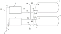
图2为本发明液态CO2储罐单元的结构示意图;Fig. 2 is the structural representation of the liquid CO2 storage tank unit of the present invention;
图3为本发明井下液态CO2供应分站的结构示意图。FIG. 3 is a schematic structural diagram of the downhole liquid CO 2 supply substation of the present invention.
图中,1.液态CO2储罐安装基础,2.液态CO2储罐,3.液态CO2储罐气相出口,4.液态CO2增压泵,5.空温式液态CO2气化器,6.液态CO2储罐液相入口,7.双相不锈钢液态CO2输送管路,8.工作面回风顺槽液态CO2驱替输送管,9.采空区液态CO2压注管路,10.煤矿主井,11.煤矿副井,12.防火采空区,13.采煤工作面回风巷,14.硐室,15.煤矿回风井,16.自力式压力调节阀,17.矿井开采水平,18.第一管道,19第二管道,20.第一阀门,21. 第二阀门,22.第三阀门,23.第三管道,24.第四管道,25.第四阀门,26.第五阀门,27.第六阀门,28.第五管道,29.第七阀门,30.第六管道,31.第七管道, 32.第八阀门,33.第九阀门,34.第十阀门,35.液态CO2输送支管,36.安全阀,37.第十一阀门,38.井下移动式液态CO2储罐。In the figure, 1. Installation foundation of liquid CO2 storage tank, 2. Liquid CO2 storage tank, 3. Gas phase outlet of liquid CO2 storage tank, 4. Liquid CO2 booster pump, 5. Air-temperature liquid CO2 gasification 6. Liquid phase inlet of liquid CO 2 storage tank, 7. Duplex stainless steel
具体实施方式Detailed ways
下面结合附图和具体实施方式对本发明进行详细说明。The present invention will be described in detail below with reference to the accompanying drawings and specific embodiments.
本发明提供煤矿井下煤自燃与瓦斯灾害液态CO2综合防治方法,如图 1-3所示,根据矿井采掘工程平面图、通风系统图和井上下对照图确定液态 CO2长距离输送系统最佳布置方式,将液态CO2通过输送管网引至所需防火采空区(12)、煤层增透工作面外,另外也可通过管路将液态CO2引至其它采区,具体按照以下步骤实施:The present invention provides a comprehensive prevention and control method for liquid CO 2 in coal spontaneous combustion and gas disasters in coal mines. As shown in Figures 1-3, the optimal arrangement of the long-distance transportation system for liquid CO 2 is determined according to the mine excavation project plan, ventilation system diagram and the comparison diagram of the upper and lower wells. method, the liquid CO 2 can be led to the required fire-proof goaf (12) and the coal seam anti-permeability working surface through the transportation pipe network, and the liquid CO 2 can also be led to other mining areas through the pipeline. The specific implementation is as follows. :
步骤1.根据矿井采掘工程平面图、通风系统图和井上下对照图确定液态CO2长距离输送系统布置方式,确保液态CO2输送管路处于回风巷道内:①如果所需采区或者工作面距离煤矿回风井15距离较近,长距离液态CO2输送管路可在回风立井内布置;②如果所需采区或者工作面距离矿井回风立井距离较远,则通过从地面向所需位置打设竖井来完成液态CO2输送管路的安装;Step 1. Determine the layout of the liquid CO 2 long-distance conveying system according to the mine excavation project plan, ventilation system diagram, and the upper and lower comparison diagrams of the mine, and ensure that the liquid CO 2 conveying pipeline is in the return air tunnel: ① If the required mining area or working face The distance from the coal mine
液态CO2长距离输送系统包括有液态CO2储罐单元及输送管网,液态 CO2储罐单元包括有液态CO2储罐安装基础1、多个液态CO2储罐2、1台液态CO2增压泵4、1台空温式液态CO2气化器5及若干个连接设备用的管道。The liquid CO 2 long-distance transportation system includes a liquid CO 2 storage tank unit and a pipeline network. The liquid CO 2 storage tank unit includes a liquid CO 2 storage tank installation base 1, multiple liquid CO 2 storage tanks 2, and a
步骤2.在步骤1中确定好的竖井打设位置或者回风井口选择位置施工液态CO2储罐安装基础,在液态CO2储罐安装基础上安装多个液态CO2储罐、1台液态CO2增压泵和1台空温式液态CO2气化器,多个液态CO2储罐的液态CO2储罐气相出口均通过管道与液态CO2增压泵的气相出口连通;多个液态CO2储罐的液态CO2储罐液相出口均通过管道与液态CO2增压泵的液相入口及空温式液态CO2气化器进口连通;液态CO2增压泵的出口及空温式液态CO2气化器的出口均通过输送管网将液态CO2引至井下所需位置;
步骤3.除了将液态CO2通过输送管网引至所需防火采空区12、煤层增透工作面外,另外也可通过管路将液态CO2引至其它采区;
步骤4.输送管网包括有双相不锈钢液态CO2输送管路7(铁素体与奥氏体各约占50%)、若干个液态CO2输送支管35,工作面回风顺槽液态CO2驱替输送管8、采空区液态CO2压注管路9;若干个液态CO2输送支管均与双相不锈钢液态CO2输送管路7连通,其中一个液态CO2输送支管设置在采煤工作面回风巷13内,该液态CO2输送支管的一侧上连接有若干个工作面回风顺槽液态CO2驱替输送管8,该液态CO2输送支管的另一侧上连接有若干个采空区液态CO2压注管路9;通过若干个采空区液态CO2压注管路9及若干个工作面回风顺槽液态CO2驱替输送管8向工作面和防火采空区12持续均匀压注液态CO2;将其余的液态CO2输送支管35设置在周边巷道;处的井下液态CO2供应分站液态CO2输送支管35上设置有安全阀36及第十一阀门37;Step 4. The conveying pipe network includes a duplex stainless steel liquid CO 2 conveying pipeline 7 (ferrite and austenite each account for about 50%), a number of liquid CO 2 conveying
步骤5.在硐室14存放多个井下移动式液态CO2储罐38作为井下液态 CO2供应分站,当采区内其他工作面或采空区需液态CO2驱替或防火时,在液态CO2供应分站完成移动式储罐充装,通过矿井现有运输系统运至液态CO2所需压注位置。
在防火所需采空区液态CO2压注管路9末端安装自力式压力调节阀16。A self-operated
设置调节阀后压力≥0.8MPa,保证压注管网中CO2以液相进行为主。After setting the regulating valve, the pressure is greater than or equal to 0.8MPa to ensure that the CO2 in the pressure injection pipe network is mainly carried out in the liquid phase.
液态CO2储罐2的容积为25m3或50m3。The liquid CO 2 storage tank 2 has a volume of 25 m 3 or 50 m 3 .
液态CO2储罐2的数量为两个。The number of liquid CO2 storage tanks 2 is two.
井下移动式液态CO2储罐38的容积为2.0m3。The volume of the downhole mobile liquid CO 2 storage tank 38 is 2.0 m 3 .
根据各矿井实际需要,当地面储罐液态CO22储存量低于10m3,及时通过液态CO2运输半挂槽车进行补充,并确定相应的补充频率和周期。According to the actual needs of each mine, when the storage capacity of
实施例Example
某矿主采煤层为高瓦斯易自燃煤层,具有煤矿主井10及煤矿副井11,矿井开采水平17如图1所示。煤层厚度较大,采用综采放顶煤开采方法。开采过程中瓦斯涌出量大、涌出异常,采后采空区丢煤量大,煤自燃威胁严重,拟采用液态CO2压注实现煤自燃和瓦斯威胁的综合防治。The main coal seam of a certain mine is a high-gas-prone coal seam, which has a
步骤1.根据矿井采掘工程平面图、通风系统图和井上下对照图确定液态CO2长距离输送系统布置方式:①如果所需采区或者工作面距离煤矿回风井15距离较近,长距离液态CO2输送管路可在回风立井内布置;②如果所需采区或者工作面距离矿井回风立井距离较远,则通过从地面向所需位置打设竖井来完成液态CO2输送管路的安装;Step 1. Determine the layout of the liquid CO 2 long-distance conveying system according to the mine excavation project plan, ventilation system diagram and the comparison diagram of the upper and lower wells of the mine: ① If the required mining area or working face is 15 minutes away from the coal mine return air shaft, the long-distance liquid CO The CO 2 conveying pipeline can be arranged in the return air shaft; ② If the required mining area or working face is far away from the mine return air shaft, the liquid CO 2 conveying pipeline can be completed by drilling a shaft from the ground to the required position installation;
液态CO2长距离输送系统包括有液态CO2储罐单元及输送管网,液态 CO2储罐单元包括有液态CO2储罐安装基础1、两个液态CO2储罐2、1台液态CO2增压泵4、1台空温式液态CO2气化器5及若干个连接设备用的管道。The liquid CO 2 long-distance transportation system includes a liquid CO 2 storage tank unit and a pipeline network. The liquid CO 2 storage tank unit includes a liquid CO 2 storage tank installation base 1, two liquid CO 2 storage tanks 2, and one
步骤2.在步骤1中确定好的竖井打设位置或者回风井口选择合适位置,施工液态CO2储罐安装基础1,在液态CO2储罐安装基础1上安装多个液态 CO2储罐2、1台液态CO2增压泵4和1台空温式液态CO2气化器5,多个液态CO2储罐2的液态CO2储罐气相出口3分别通过第一管道18及第二管道19与液态CO2增压泵4的气相出口连通,第一管道18上设置有第一阀门20,第二管道19上设置有第三阀门21及第三阀门22;两个液态CO2储罐2 的液态CO2储罐液相出口6分别通过第三管道23及第四管道24与液态CO2增压泵4的液相出口连接,第三管道23上设置有第四阀门25,第四管道24 上设置有第五阀门26及第六阀门27;第三管道23还通过第五管道28与空温式液态CO2气化器5进口连通,第五管道28上设置有第七阀门29;液态 CO2增压泵4的出口及空温式液态CO2气化器5的出口均通过输送管网将液态CO2引至井下所需位置;
输送管网包括有双相不锈钢液态CO2输送管路7、第六管道30及第七管道31,第六管道30与空温式液态CO2气化器5出口连接;第七管道31 与液态CO2增压泵4的出口连接;第六管道30上设置有第八阀门32,第七管道31上设置有第九阀门33,双相不锈钢液态CO2输送管路7上设置有第十阀门34;第六管道30及第七管道31均与双相不锈钢液态CO2输送管路7的一端连通;双相不锈钢液态CO2输送管路7的另一端与若干个液态CO2输送支管连通;The transportation pipeline network includes a duplex stainless steel liquid CO 2 transportation pipeline 7, a
步骤3.除了将液态CO2通过输送管网引至所需防火采空区12、煤层增透工作面外,另外也可通过管路将液态CO2引至其它采区;
步骤4.输送管网包括有双相不锈钢液态CO2输送管路7(铁素体与奥氏体各约占50%)、若干个液态CO2输送支管,工作面回风顺槽液态CO2驱替输送管8、采空区液态CO2压注管路9;若干个液态CO2输送支管均与双相不锈钢液态CO2输送管路7连通,其中一个液态CO2输送支管设置在采煤工作面回风巷13内,该液态CO2输送支管的一侧上连接有若干个工作面回风顺槽液态CO2驱替输送管8,该液态CO2输送支管的另一侧上连接有若干个采空区液态CO2压注管路9;通过若干个采空区液态CO2压注管路9及若干个工作面回风顺槽液态CO2驱替输送管8向工作面和防火采空区12持续均匀压注液态CO2;将其余的液态CO2输送支管设置在周边巷道;Step 4. The conveying pipe network includes a duplex stainless steel liquid CO 2 conveying pipeline 7 (ferrite and austenite each account for about 50%), several liquid CO 2 conveying branch pipes, and the working face return air flows along the tank for liquid CO 2 Displacement pipeline 8, goaf liquid CO 2 injection pipeline 9; several liquid CO 2 delivery branches are all connected with duplex stainless steel liquid CO 2 delivery pipeline 7, and one of the liquid CO 2 delivery branches is set in the coal mining area In the working face return air lane 13, one side of the liquid CO 2 conveying branch pipe is connected with a number of working face return air along the tank liquid CO 2 displacement conveying pipe 8, and the other side of the liquid CO 2 conveying branch pipe is connected with Several goaf liquid CO 2 pressure injection pipelines 9; through several goaf liquid CO 2 pressure injection pipelines 9 and several working face return air along the tank liquid CO 2 displacement pipeline 8 to the working face and fire prevention. The
步骤5.在硐室14存放多个井下移动式液态CO2储罐38作为井下液态 CO2供应分站,当采区内其他工作面或采空区需液态CO2驱替或防火时,在液态CO2供应分站完成移动式储罐充装,通过矿井现有运输系统运至液态 CO2所需压注位置。
在防火所需采空区液态CO2压注管路9末端安装自力式压力调节阀16。A self-operated
设置调节阀后压力≥0.8MPa,保证压注管网中CO2以液相进行为主。After setting the regulating valve, the pressure is greater than or equal to 0.8MPa to ensure that the CO2 in the pressure injection pipe network is mainly carried out in the liquid phase.
液态CO2储罐2的容积为50m3。The liquid CO 2 storage tank 2 has a volume of 50 m 3 .
液态CO2储罐2的数量为两个。The number of liquid CO2 storage tanks 2 is two.
井下移动式液态CO2储罐38的容积为2.0m3。The volume of the downhole mobile liquid CO 2 storage tank 38 is 2.0 m 3 .
Claims (7)
Priority Applications (1)
| Application Number | Priority Date | Filing Date | Title |
|---|---|---|---|
| CN202210227470.6A CN114517707A (en) | 2022-03-08 | 2022-03-08 | Liquid CO for spontaneous combustion of coal and gas disaster in underground coal mine2Comprehensive prevention and control mode |
Applications Claiming Priority (1)
| Application Number | Priority Date | Filing Date | Title |
|---|---|---|---|
| CN202210227470.6A CN114517707A (en) | 2022-03-08 | 2022-03-08 | Liquid CO for spontaneous combustion of coal and gas disaster in underground coal mine2Comprehensive prevention and control mode |
Publications (1)
| Publication Number | Publication Date |
|---|---|
| CN114517707A true CN114517707A (en) | 2022-05-20 |
Family
ID=81598968
Family Applications (1)
| Application Number | Title | Priority Date | Filing Date |
|---|---|---|---|
| CN202210227470.6A Pending CN114517707A (en) | 2022-03-08 | 2022-03-08 | Liquid CO for spontaneous combustion of coal and gas disaster in underground coal mine2Comprehensive prevention and control mode |
Country Status (1)
| Country | Link |
|---|---|
| CN (1) | CN114517707A (en) |
Cited By (3)
| Publication number | Priority date | Publication date | Assignee | Title |
|---|---|---|---|---|
| CN116639418A (en) * | 2023-05-31 | 2023-08-25 | 深圳市博德维环境技术股份有限公司 | A coal storage device and a long-term coal storage method based on liquid-gas phase transition |
| CN119435086A (en) * | 2024-12-02 | 2025-02-14 | 中国矿业大学 | Hidden fire source prevention device and method |
| CN120273782A (en) * | 2025-06-12 | 2025-07-08 | 中国矿业大学 | Mine CO2Direct capturing-geological utilization-mineralization sealing and storage integrated method |
Citations (7)
| Publication number | Priority date | Publication date | Assignee | Title |
|---|---|---|---|---|
| SE9503733D0 (en) * | 1995-10-24 | 1995-10-24 | Aga Ab | Methods and apparatus for cooling tools, workpieces or the like with condensed gas |
| KR20100068090A (en) * | 2008-12-12 | 2010-06-22 | 한국해양연구원 | Experimental facility for transport process in co2 marine geological storage |
| WO2016090937A1 (en) * | 2014-12-12 | 2016-06-16 | 中国矿业大学 | Method for efficiently treating spontaneous ignition of remaining coal in large area goaf of shallow-buried coal bed |
| CN107859530A (en) * | 2017-11-07 | 2018-03-30 | 中国矿业大学(北京) | A kind of ultra close distance coal seam exploitation gas controls method altogether with coal spontaneous combustion |
| CN108843369A (en) * | 2018-05-24 | 2018-11-20 | 山东科技大学 | A kind of mining liquid CO2The straight injection system in ground and method |
| CN210239733U (en) * | 2019-06-13 | 2020-04-03 | 国家能源投资集团有限责任公司 | Fire-fighting system in coal goaf |
| CN111810218A (en) * | 2020-06-16 | 2020-10-23 | 山东科技大学 | A kind of downhole liquid CO2 phase change dynamic multifunctional perfusion system and using method |
-
2022
- 2022-03-08 CN CN202210227470.6A patent/CN114517707A/en active Pending
Patent Citations (8)
| Publication number | Priority date | Publication date | Assignee | Title |
|---|---|---|---|---|
| SE9503733D0 (en) * | 1995-10-24 | 1995-10-24 | Aga Ab | Methods and apparatus for cooling tools, workpieces or the like with condensed gas |
| KR20100068090A (en) * | 2008-12-12 | 2010-06-22 | 한국해양연구원 | Experimental facility for transport process in co2 marine geological storage |
| WO2016090937A1 (en) * | 2014-12-12 | 2016-06-16 | 中国矿业大学 | Method for efficiently treating spontaneous ignition of remaining coal in large area goaf of shallow-buried coal bed |
| CN107859530A (en) * | 2017-11-07 | 2018-03-30 | 中国矿业大学(北京) | A kind of ultra close distance coal seam exploitation gas controls method altogether with coal spontaneous combustion |
| CN108843369A (en) * | 2018-05-24 | 2018-11-20 | 山东科技大学 | A kind of mining liquid CO2The straight injection system in ground and method |
| CN210239733U (en) * | 2019-06-13 | 2020-04-03 | 国家能源投资集团有限责任公司 | Fire-fighting system in coal goaf |
| CN111810218A (en) * | 2020-06-16 | 2020-10-23 | 山东科技大学 | A kind of downhole liquid CO2 phase change dynamic multifunctional perfusion system and using method |
| WO2021253593A1 (en) * | 2020-06-16 | 2021-12-23 | 山东科技大学 | Downhole liquid co2 phase transition-powered multi-functional filling system and usage method |
Non-Patent Citations (1)
| Title |
|---|
| 袁亮: "煤矿总工程师技术手册", 31 July 2010, 煤炭工业出版社, pages: 1763 - 1769 * |
Cited By (3)
| Publication number | Priority date | Publication date | Assignee | Title |
|---|---|---|---|---|
| CN116639418A (en) * | 2023-05-31 | 2023-08-25 | 深圳市博德维环境技术股份有限公司 | A coal storage device and a long-term coal storage method based on liquid-gas phase transition |
| CN119435086A (en) * | 2024-12-02 | 2025-02-14 | 中国矿业大学 | Hidden fire source prevention device and method |
| CN120273782A (en) * | 2025-06-12 | 2025-07-08 | 中国矿业大学 | Mine CO2Direct capturing-geological utilization-mineralization sealing and storage integrated method |
Similar Documents
| Publication | Publication Date | Title |
|---|---|---|
| CN114517707A (en) | Liquid CO for spontaneous combustion of coal and gas disaster in underground coal mine2Comprehensive prevention and control mode | |
| CN115199331B (en) | Carbon dioxide storage method based on deep goaf space in thick loose layers | |
| CN112943343B (en) | Efficient and rapid fire extinguishing method for ground drilling of different types of fires in coal mine goaf | |
| US12000626B2 (en) | Geothermal development system and the construction method thereof | |
| CN109488370B (en) | Underground limestone water exploration and drainage drilling construction method | |
| CN114876572A (en) | Underground gas storage and its site selection and reconstruction method | |
| CN110878697A (en) | Shield underwater receiving method next to urban main road in high-water-rich sandy gravel stratum | |
| CN113803104B (en) | Method for integrally arranging upper mining area buried pipe and downward drilling and extracting full-period gas | |
| CN107420126B (en) | Pressure equalizing circulation mine gas extraction system | |
| CN110030745A (en) | A kind of geothermal exploitation system and its construction method | |
| US20240301782A1 (en) | Method for remining residual coal pillar in residual mining area by collaboration of pillar-side backfilling and in-situ gasification | |
| CN114562404A (en) | A coal mine pumped storage power generation system and construction method | |
| CN110159245A (en) | Distribution note exhaust passage narrow strips coal underground gasifying furnace production system and method | |
| CN112012782B (en) | Advanced closed area gas prevention and control technology for air inlet and return roadway of fully mechanized caving face | |
| CN108952719B (en) | Method for coal loss in coal seam gasification re-mining under fully mechanized caving mining condition | |
| CN117108258A (en) | Accurate advanced gas treatment method for large area of underground thick coal seam of coal mine | |
| CN115573766B (en) | Integrated device and method for underground coal gasification and solid waste pyrolysis | |
| CN119572297B (en) | Carbon storage space construction method for negative carbon filling exploitation | |
| US20130061592A1 (en) | Process for Maximization and Optimization of Coal Energy | |
| CN212027764U (en) | Pre-control structure of an underground gasifier and gasifier | |
| CN100406676C (en) | Underground gasification production mine | |
| CN108775240A (en) | A kind of method of half-edge coal seam fluidization exploitation | |
| WO2021179684A1 (en) | Underground gasifier pre-control structure, gasifier, and gasification method | |
| CN117514351A (en) | A method of arranging hydrogen storage using abandoned mine coal pillars | |
| CN115961933A (en) | A comprehensive utilization method for underground in-situ transformation of oil-rich coal |
Legal Events
| Date | Code | Title | Description |
|---|---|---|---|
| PB01 | Publication | ||
| PB01 | Publication | ||
| SE01 | Entry into force of request for substantive examination | ||
| SE01 | Entry into force of request for substantive examination |