CN114504728A - A sensor for cardiac blood pump and cardiac blood pump - Google Patents
A sensor for cardiac blood pump and cardiac blood pump Download PDFInfo
- Publication number
- CN114504728A CN114504728A CN202011289526.8A CN202011289526A CN114504728A CN 114504728 A CN114504728 A CN 114504728A CN 202011289526 A CN202011289526 A CN 202011289526A CN 114504728 A CN114504728 A CN 114504728A
- Authority
- CN
- China
- Prior art keywords
- pressure sensing
- sensor
- blood pump
- optical signal
- blood
- Prior art date
- Legal status (The legal status is an assumption and is not a legal conclusion. Google has not performed a legal analysis and makes no representation as to the accuracy of the status listed.)
- Pending
Links
- 239000008280 blood Substances 0.000 title claims abstract description 94
- 210000004369 blood Anatomy 0.000 title claims abstract description 94
- 230000000747 cardiac effect Effects 0.000 title claims abstract description 26
- 230000003287 optical effect Effects 0.000 claims abstract description 60
- 230000003068 static effect Effects 0.000 claims abstract description 55
- 230000008054 signal transmission Effects 0.000 claims abstract description 47
- 239000012528 membrane Substances 0.000 claims abstract description 44
- 230000017531 blood circulation Effects 0.000 claims abstract description 15
- 239000003292 glue Substances 0.000 claims description 5
- 239000000463 material Substances 0.000 claims description 4
- 239000004642 Polyimide Substances 0.000 claims description 3
- 239000013307 optical fiber Substances 0.000 claims description 3
- 229920001721 polyimide Polymers 0.000 claims description 3
- 230000014759 maintenance of location Effects 0.000 abstract description 7
- 208000007536 Thrombosis Diseases 0.000 abstract description 6
- 230000015572 biosynthetic process Effects 0.000 abstract description 6
- 230000007774 longterm Effects 0.000 abstract description 3
- 238000005259 measurement Methods 0.000 abstract description 3
- 238000010586 diagram Methods 0.000 description 9
- 230000036772 blood pressure Effects 0.000 description 8
- 230000002861 ventricular Effects 0.000 description 8
- 230000005540 biological transmission Effects 0.000 description 4
- 238000000034 method Methods 0.000 description 4
- 238000013461 design Methods 0.000 description 3
- 210000005240 left ventricle Anatomy 0.000 description 3
- 210000001519 tissue Anatomy 0.000 description 3
- 206010019280 Heart failures Diseases 0.000 description 2
- 230000001746 atrial effect Effects 0.000 description 2
- 230000002706 hydrostatic effect Effects 0.000 description 2
- 210000005241 right ventricle Anatomy 0.000 description 2
- 238000011282 treatment Methods 0.000 description 2
- 230000004872 arterial blood pressure Effects 0.000 description 1
- 230000008081 blood perfusion Effects 0.000 description 1
- 239000000919 ceramic Substances 0.000 description 1
- 238000001514 detection method Methods 0.000 description 1
- 230000003205 diastolic effect Effects 0.000 description 1
- 208000037265 diseases, disorders, signs and symptoms Diseases 0.000 description 1
- 238000002651 drug therapy Methods 0.000 description 1
- 230000000694 effects Effects 0.000 description 1
- 238000005516 engineering process Methods 0.000 description 1
- 239000000835 fiber Substances 0.000 description 1
- 239000012530 fluid Substances 0.000 description 1
- 239000011521 glass Substances 0.000 description 1
- 210000005003 heart tissue Anatomy 0.000 description 1
- 238000002513 implantation Methods 0.000 description 1
- 238000009434 installation Methods 0.000 description 1
- CNQCVBJFEGMYDW-UHFFFAOYSA-N lawrencium atom Chemical compound [Lr] CNQCVBJFEGMYDW-UHFFFAOYSA-N 0.000 description 1
- 238000012986 modification Methods 0.000 description 1
- 230000004048 modification Effects 0.000 description 1
- 230000008092 positive effect Effects 0.000 description 1
- 238000012545 processing Methods 0.000 description 1
- 230000001681 protective effect Effects 0.000 description 1
- 230000002685 pulmonary effect Effects 0.000 description 1
- 238000005086 pumping Methods 0.000 description 1
- 238000006748 scratching Methods 0.000 description 1
- 230000002393 scratching effect Effects 0.000 description 1
- 230000035945 sensitivity Effects 0.000 description 1
- 208000011580 syndromic disease Diseases 0.000 description 1
- 238000004804 winding Methods 0.000 description 1
Images


Landscapes
- Measuring Pulse, Heart Rate, Blood Pressure Or Blood Flow (AREA)
- External Artificial Organs (AREA)
Abstract
本发明提供了一种用于心脏血泵的传感器及心脏血泵,传感器包括设置在心脏血泵输送套管上的静压感知端,所述静压感知端用于检测所述输送套管外侧流经血液的静压;所述静压感知端包括有压力感知膜芯片和光信号传输线,所述压力感知膜芯片具有与血液接触的压力感知面,所述压力感知面平行于所述输送套管的轴向,所述压力感知膜芯片获取垂直于血流流动方向上的静压信号并通过所述光信号传输线输送出去。本发明提供的传感器,压力感知面与血液流动方向平行,直接测量血液静压,无需在静压感知端设置血液滞留区来测量血液静压,从而避免形成血栓,保证在血液流动时也能测量血液静压,可用于短、长期心脏内血泵支持。
The present invention provides a sensor for a cardiac blood pump and a cardiac blood pump. The sensor includes a static pressure sensing end arranged on a conveying sleeve of the cardiac blood pump, and the static pressure sensing end is used to detect the outside of the conveying sleeve. Static pressure flowing through blood; the static pressure sensing end includes a pressure sensing membrane chip and an optical signal transmission line, the pressure sensing membrane chip has a pressure sensing surface in contact with blood, and the pressure sensing surface is parallel to the delivery sleeve The pressure sensing membrane chip acquires a static pressure signal perpendicular to the direction of blood flow and transmits it through the optical signal transmission line. In the sensor provided by the present invention, the pressure sensing surface is parallel to the blood flow direction, and the static pressure of the blood is directly measured without setting a blood retention area at the static pressure sensing end to measure the static pressure of the blood, thereby avoiding the formation of thrombus and ensuring that the measurement can be performed even when the blood is flowing. Blood static pressure, which can be used for short and long-term intracardiac blood pump support.
Description
技术领域technical field
本发明涉及医疗器械设计技术领域,具体涉及一种用于心脏血泵的传感器及心脏血泵。The invention relates to the technical field of medical device design, in particular to a sensor for a cardiac blood pump and a cardiac blood pump.
背景技术Background technique
心衰指由于心脏的收缩功能和(或)舒张功能发生障碍,不能将静脉回心血量充分排出心脏,导致静脉系统血液淤积,动脉系统血液灌注不足,从而引起心脏循环障碍症候群。目前心衰治疗的手段包括有药物治疗、手术换心脏、左心室辅助装置。其中左心室辅助装置即为通过心脏血泵对血液进行抽吸,促进心脏血液的流动,该方案具有治疗效果好,成本低等优点。Heart failure refers to the failure of the systolic and/or diastolic function of the heart to fully discharge the venous blood back to the heart, resulting in blood stasis in the venous system and insufficient blood perfusion in the arterial system, resulting in cardiac circulatory disorder syndrome. Current treatments for heart failure include drug therapy, surgical replacement of the heart, and left ventricular assist devices. Among them, the left ventricular assist device is to pump blood through a heart blood pump to promote the flow of heart blood. This solution has the advantages of good treatment effect and low cost.
对于目前的心脏内血泵,为了感知血管内压强,通常会采用压力传感器。专利(US9669142)提供了一种压力传感器,固定在血泵导管上,这种压力传感器为了测量出不受血液流速影响的血液静压,需要在传感器感知面的周围增加额外的“围墙”零件,从而营造一个血液滞留区域,从而来测量血液的静压;这种方案一方面结构复杂,另一方面时间长后容易在血液滞留区域内形成血栓。而且,该压力传感器中压力感知面与导管轴线正交,对装配工艺要求较高,装配麻烦。For the current intracardiac blood pump, in order to sense the intravascular pressure, a pressure sensor is usually used. The patent (US9669142) provides a pressure sensor, which is fixed on the blood pump catheter. In order to measure the static pressure of the blood that is not affected by the blood flow rate, the pressure sensor needs to add additional "wall" parts around the sensing surface of the sensor. Thereby, a blood retention area is created to measure the static pressure of blood; on the one hand, this solution has a complicated structure, and on the other hand, it is easy to form a thrombus in the blood retention area after a long time. In addition, the pressure sensing surface of the pressure sensor is orthogonal to the axis of the catheter, which requires a higher assembly process and is troublesome to assemble.
发明内容SUMMARY OF THE INVENTION
针对背景技术中的问题,本发明提供了一种用于心脏血泵的传感器,包括设置在心脏血泵输送套管上的静压感知端,所述静压感知端用于检测所述输送套管外侧流经血液的静压;所述静压感知端包括有压力感知膜芯片和光信号传输线,所述压力感知膜芯片具有与血液接触的压力感知面,所述压力感知面平行于所述输送套管的轴向,所述压力感知膜芯片获取垂直于血流流动方向上的静压信号并通过所述光信号传输线输送出去。In view of the problems in the background art, the present invention provides a sensor for a cardiac blood pump, comprising a static pressure sensing end arranged on a delivery sleeve of the cardiac blood pump, and the static pressure sensing end is used to detect the delivery sleeve The static pressure of the blood flowing through the outside of the tube; the static pressure sensing end includes a pressure sensing membrane chip and an optical signal transmission line, the pressure sensing membrane chip has a pressure sensing surface in contact with the blood, and the pressure sensing surface is parallel to the conveying In the axial direction of the sleeve, the pressure sensing membrane chip acquires a static pressure signal perpendicular to the direction of blood flow and transmits it through the optical signal transmission line.
在一些实施例中,所述压力感知膜芯片和所述光信号传输线均平行于所述输送套管的轴向设置,所述压力感知膜芯片和所述光信号传输线之间设置有用于将垂直光信号转换成水平光信号的路径元件。In some embodiments, both the pressure sensing film chip and the optical signal transmission line are arranged parallel to the axial direction of the delivery sleeve, and a vertical connection is arranged between the pressure sensing film chip and the optical signal transmission line. A path element that converts an optical signal into a horizontal optical signal.
在一些实施例中,所述路径元件采用直角反射棱镜,所述直角反射棱镜包括有相邻的第一直角面和第二直角面、连接所述第一直角面和第二直角面的斜面,所述第一直角面平行于所述压力感知膜芯片连接设置,所述第二直角面平行于所述光信号传输线远端端面并连接,所述斜面上设有反射膜。In some embodiments, the path element adopts a right-angle reflective prism, and the right-angle reflective prism includes adjacent first and second right-angle surfaces, and an inclined surface connecting the first and second right-angle surfaces, The first right-angle surface is connected and arranged parallel to the pressure sensing film chip, the second right-angle surface is parallel to and connected to the distal end surface of the optical signal transmission line, and a reflective film is provided on the inclined surface.
在一些实施例中,所述第二直角面与所述光信号传输线之间设置有自聚焦透镜。In some embodiments, a self-focusing lens is disposed between the second right-angle surface and the optical signal transmission line.
在一些实施例中,所述压力感知膜芯片垂直连接于所述光信号传输线的远端,所述光信号传输线远端的轴向垂直于所述输送套管的轴向。In some embodiments, the pressure sensing membrane chip is vertically connected to the distal end of the optical signal transmission line, and the axial direction of the distal end of the optical signal transmission line is perpendicular to the axial direction of the delivery sleeve.
在一些实施例中,还包括有护套,所述光信号传输线设置在所述护套内并沿其轴向延伸设置;所述压力感知膜芯片置于所述护套的远端构成所述静压感知端,所述护套上对应处设置有用于露出所述压力感知面与血液接触的开口。In some embodiments, a sheath is further included, and the optical signal transmission line is disposed in the sheath and extends along its axial direction; the pressure sensing membrane chip is disposed at the distal end of the sheath to constitute the At the static pressure sensing end, an opening for exposing the pressure sensing surface to be in contact with blood is provided at a corresponding position on the sheath.
在一些实施例中,所述压力感知膜芯片置于所述开口内,且所述压力感知面不超出所述套管结构的外壁面。In some embodiments, the pressure sensing membrane chip is placed in the opening, and the pressure sensing surface does not exceed the outer wall surface of the sleeve structure.
在一些实施例中,所述护套为套管结构,所述套管结构设置在所述输送套管的外壁面上或者内壁面上或者管壁内;In some embodiments, the sheath is a sleeve structure, and the sleeve structure is disposed on the outer wall surface or the inner wall surface or in the tube wall of the delivery sleeve;
或者,所述输送套管的管壁内开设通道构成所述护套。Alternatively, a channel is opened in the pipe wall of the delivery sleeve to form the sheath.
在一些实施例中,所述套管结构设置在所述输送套管的外壁面上;所述输送套管的外壁面上设置有凹槽,所述套管结构至少部分定位于所述凹槽内。In some embodiments, the sleeve structure is provided on the outer wall surface of the delivery sleeve; the outer wall surface of the delivery sleeve is provided with a groove, and the sleeve structure is at least partially positioned in the groove Inside.
在一些实施例中,所述套管结构通过生物相容性胶水粘接在所述凹槽内。In some embodiments, the sleeve structure is bonded in the groove by a biocompatible glue.
在一些实施例中,所述套管结构的材料采用聚酰亚胺。In some embodiments, the material of the sleeve structure is polyimide.
在一些实施例中,所述套管结构的直径不超过0.5mmIn some embodiments, the diameter of the sleeve structure does not exceed 0.5 mm
在一些实施例中,所述套管结构的末端呈圆弧状。In some embodiments, the end of the sleeve structure is arcuate.
在一些实施例中,所述光信号传输线采用光纤。In some embodiments, the optical signal transmission line employs optical fibers.
本发明还提供了一种心脏血泵,所述心脏血泵的输送套管上设置有至少一个压力传感器,所述压力传感器采用如上所述的传感器。The present invention also provides a cardiac blood pump, at least one pressure sensor is provided on the delivery sleeve of the cardiac blood pump, and the pressure sensor adopts the above-mentioned sensor.
本发明由于采用以上技术方案,使之与现有技术相比,具有以下的优点和积极效果:Compared with the prior art, the present invention has the following advantages and positive effects due to the adoption of the above technical solutions:
本发明提供的传感器压力感知面与血液流动方向平行,直接测量血液静压,无需在静压感知端设置血液滞留区来测量血液静压,从而避免形成血栓,保证在血液流动时也能测量血液静压,可用于短、长期心脏内血泵支持;而且不需要额外的“围墙”零件,结构简单,传感器系统直径尺寸更小,植入时对人体组织损伤更小;另外,压力感知面与输送套管的轴向平行设计,直接测量血液静压,不需要压力感知面与输送套管轴线正交,对装配工艺要求较低。The pressure sensing surface of the sensor provided by the invention is parallel to the blood flow direction, and the static pressure of the blood is directly measured without setting a blood retention area at the static pressure sensing end to measure the static pressure of the blood, thereby avoiding the formation of thrombus and ensuring that the blood can also be measured when the blood is flowing. Static pressure, can be used for short and long-term intracardiac blood pump support; and does not require additional "enclosure" parts, the structure is simple, the diameter of the sensor system is smaller, and the damage to human tissue is less when implanted; in addition, the pressure sensing surface and The axial-parallel design of the delivery cannula directly measures the static pressure of blood, and does not require the pressure sensing surface to be orthogonal to the axis of the delivery cannula, which requires less assembly technology.
附图说明Description of drawings
结合附图,通过下文的述详细说明,可更清楚地理解本发明的上述及其他特征和优点,其中:The above and other features and advantages of the present invention will be more clearly understood from the following detailed description in conjunction with the accompanying drawings, wherein:
图1为流体静压示意图;Fig. 1 is a schematic diagram of hydrostatic pressure;
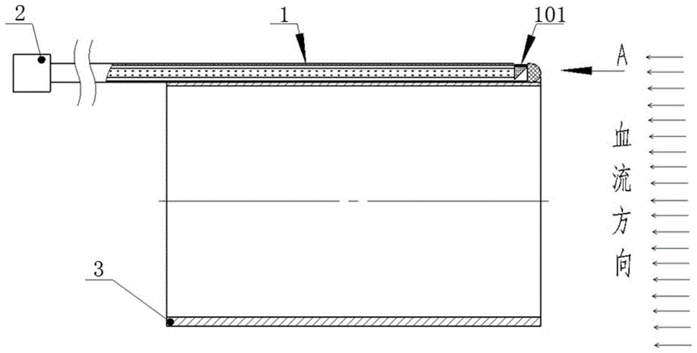
图2为本发明实施例1中用于心脏血泵的传感器的结构示意图;2 is a schematic structural diagram of a sensor for a cardiac blood pump in
图3为本发明实施例1中静压感知端的剖示意图;3 is a schematic cross-sectional view of a static pressure sensing end in
图4为本发明实施例1中直角反射棱镜的结构示意图;4 is a schematic structural diagram of a right-angle reflecting prism in
图5为图2中的A向示意图中径向密封件的结构示意图;5 is a schematic structural diagram of a radial seal in the A-direction schematic diagram in FIG. 2;
图6为本发明实施例2中用于心脏血泵的传感器的结构示意图;6 is a schematic structural diagram of a sensor for a cardiac blood pump in
图7为本发明实施例2中静压感知端的剖示意图;7 is a schematic cross-sectional view of a static pressure sensing end in
图8为图6中D处的放大示意图;Fig. 8 is the enlarged schematic diagram at D in Fig. 6;
图9为图6中的B向示意图;Fig. 9 is the schematic diagram of direction B in Fig. 6;
图10为图6中的C向示意图。FIG. 10 is a schematic diagram of the direction C in FIG. 6 .
具体实施方式Detailed ways
参见示出本发明实施例的附图,下文将更详细地描述本发明。然而,本发明可以以许多不同形式实现,并且不应解释为受在此提出之实施例的限制。相反,提出这些实施例是为了达成充分及完整公开,并且使本技术领域的技术人员完全了解本发明的范围。这些附图中,为清楚起见,可能放大了层及区域的尺寸及相对尺寸。The present invention will hereinafter be described in more detail with reference to the accompanying drawings, which illustrate embodiments of the invention. However, the present invention may be embodied in many different forms and should not be construed as limited by the embodiments set forth herein. Rather, these embodiments are presented so that this disclosure will be thorough and complete, and will fully convey the scope of the invention to those skilled in the art. In the drawings, the size and relative sizes of layers and regions may be exaggerated for clarity.
需要说明,本发明实施例中所有方向性指示(诸如上、下、左、右、前、后……)仅用于解释在某一特定姿态(如附图所示)下各部件之间的相对位置关系、运动情况等,如果该特定姿态发生改变时,则该方向性指示也相应地随之改变。It should be noted that all directional indications (such as up, down, left, right, front, back, etc.) in the embodiments of the present invention are only used to explain the relationship between various components under a certain posture (as shown in the accompanying drawings). The relative positional relationship, the movement situation, etc., if the specific posture changes, the directional indication also changes accordingly.
本发明提供了一种用于心脏血泵的传感器,包括设置在心脏血泵的输送套管上的静压感知端,静压感知端用于检测输送套管外侧流经血液的静压;静压感知端包括有压力感知膜芯片和光信号传输线,压力感知膜芯片具有与血液接触的压力感知面,压力感知面平行于输送套管的轴向,压力感知膜芯片获取垂直于血流流动方向上的静压信号并通过光信号传输线输送出去。The invention provides a sensor for a cardiac blood pump, comprising a static pressure sensing end arranged on a conveying sleeve of the cardiac blood pump, and the static pressure sensing end is used to detect the static pressure of the blood flowing through the outside of the conveying sleeve; The pressure sensing end includes a pressure sensing membrane chip and an optical signal transmission line. The pressure sensing membrane chip has a pressure sensing surface in contact with blood, the pressure sensing surface is parallel to the axial direction of the delivery sleeve, and the pressure sensing membrane chip captures the flow direction perpendicular to the blood flow. The static pressure signal is sent out through the optical signal transmission line.
其中,心脏血泵的输送套管的轴向沿着心脏内血液的流动方向,传感器随输送套管一起被送入到心脏内用于测量心脏内的血液的静压,静压能表征心脏血泵的工作性能(流量、主动脉压强、左心室压强、泵血功率),反映血泵是否处于正常工作状态,以便于后续对心脏血泵进行数据调整等操作。The axial direction of the delivery sleeve of the cardiac blood pump is along the flow direction of the blood in the heart, and the sensor is sent into the heart together with the delivery sleeve to measure the static pressure of the blood in the heart. The static pressure can represent the blood flow of the heart. The working performance of the pump (flow rate, aortic pressure, left ventricular pressure, and pumping power) reflects whether the blood pump is in a normal working state, so as to facilitate subsequent operations such as data adjustment of the cardiac blood pump.
本发明提供的传感器通过将与血液接触的压力感知面设置为平行于输送套管的轴向,即从而使得压力感知面平行于血液流动方向,从而使其直接可以测量出血液的静压(其中关于静压的解释如图1中所示,垂直于流体流动方向上的压力即为流体静压);压力感知膜芯片将获取的静压通过光信号传输线传递至后台控制器,后台控制器用于处理光纤信号并进行显示。本发明压力感知面与血液流动方向平行,直接测量血液静压,无需在静压感知端设置血液滞留区来测量血液静压,从而避免形成血栓,保证在血液流动时也能测量血液静压,可用于短、长期心脏内血泵支持;而且不需要额外的“围墙”零件,结构简单,传感器系统直径尺寸更小,植入时对人体组织损伤更小;另外,压力感知面与输送套管的轴向平行设计,直接测量血液静压,不需要压力感知面与输送套管轴线正交,对装配工艺要求较低。The sensor provided by the present invention can directly measure the static pressure of the blood by setting the pressure sensing surface in contact with the blood to be parallel to the axial direction of the delivery sleeve, that is, to make the pressure sensing surface parallel to the blood flow direction (wherein The explanation of static pressure is shown in Figure 1, the pressure perpendicular to the fluid flow direction is the hydrostatic pressure); the pressure sensing membrane chip transmits the acquired static pressure to the background controller through the optical signal transmission line, and the background controller is used for Process fiber optic signals and display them. The pressure sensing surface of the present invention is parallel to the blood flow direction, and the static blood pressure is directly measured without setting a blood retention area at the static pressure sensing end to measure the blood static pressure, thereby avoiding the formation of thrombus and ensuring that the blood static pressure can also be measured when the blood is flowing. It can be used for short and long-term intracardiac blood pump support; and does not require additional "enclosure" parts, the structure is simple, the diameter of the sensor system is smaller, and the damage to human tissue is less when implanted; in addition, the pressure sensing surface and delivery cannulae The axial-parallel design of the device can directly measure the static pressure of blood, and it does not need the pressure sensing surface to be orthogonal to the axis of the delivery sleeve, which requires less assembly process.
下面就具体实施例作进一步的说明:The specific embodiments are further described below:
实施例1Example 1
参照图2-5,在本实施例中传感器1包括有压力感知膜芯片101和光信号传输线102,压力感知膜芯片101和光信号传输线102均平行于输送套管3的轴向设置;光信号传输线102的近端连接后台控制器2,远端通过路径元件与压力感知膜芯片101连接,路径元件103用于将垂直光信号(垂直于压力感知膜芯片101方向上的光信号)转换成水平光信号(平行于光信号传输线102方向上的光信号)。2-5, in this embodiment, the
在本实施例中,优选的光信号传输线102采用光纤,当然在其他实施例中也可采用其他同等功能的光信号传输线,此处不做限制。In this embodiment, the optical
在本实施例中,压力感知膜芯片由压力感知膜和芯片组成,压力感知膜与芯片平行设置,且两者之间留有间隙使得两者之间形成标准腔长,压力感知膜与血液接触感知紧压,芯片与光信号传输线连接实现光信号的传输;压力感知膜受静压后,压力感知膜向芯片一侧内凹变形,压力感知膜和芯片之间的距离缩短,即腔长发生变化;从而使得光传输的形成发生变化,后台控制器可以获得静压前后的光传输形成,行程,后台控制器计算不同的光传输行程能与压力值一一对应,从而可获得静压值。In this embodiment, the pressure sensing membrane chip is composed of a pressure sensing membrane and a chip, the pressure sensing membrane and the chip are arranged in parallel, and there is a gap between them so that a standard cavity length is formed between them, and the pressure sensing membrane is in contact with blood When the pressure is sensed, the chip is connected with the optical signal transmission line to realize the transmission of the optical signal; after the pressure sensing film is subjected to static pressure, the pressure sensing film is concavely deformed to one side of the chip, and the distance between the pressure sensing film and the chip is shortened, that is, the cavity length occurs. Therefore, the formation of light transmission changes, and the background controller can obtain the formation and stroke of light transmission before and after the static pressure.
在本实施例中,压力感知膜采用生物相容性的陶瓷膜或玻璃膜等,此处不做限制,可根据具体情况进行调整。In this embodiment, the pressure sensing membrane adopts a biocompatible ceramic membrane or glass membrane, etc., which is not limited here, and can be adjusted according to specific conditions.
在本实施例中,路径元件采用直角反射棱镜103;具体的,参照图3-4,直角反射棱镜103包括有相邻的第一直角面1031和第二直角面1032、连接第一直角面1031和第二直角面1032的斜面1033;第一直角面1031平行于压力感知膜芯片101相对设置,且第一直角面1031与压力感知膜芯片101连接;第二直角面1032平行于光信号传输线102远端的端面相对设置,且第二直角面1032与光信号传输线102远端连接;斜面1033上设有反射膜,通过直角反射棱镜103的设置,光信号在反射膜的作用下弯折90°实现平行设置的光信号传输线102与压力感知膜芯片101之间的光信号的传输。In this embodiment, the path element adopts a right-
当然,其他实施例中路径元件的具体结构并不局限于以上所述,也可选择其他结构的棱镜或者光学元件,只要能够改变光信号传输方向即可,此处不做限制,可根据具体情况进行选择。Of course, the specific structures of the path elements in other embodiments are not limited to the above, and prisms or optical elements of other structures can also be selected, as long as the optical signal transmission direction can be changed, which is not limited here, and can be determined according to specific circumstances. to make a selection.
进一步的,第二直角面1032与光信号传输线102之间增加自聚焦透镜,用于增加光信号的灵敏度,从而有利于减少测量误差;当然在其他实施例中也可省略自聚焦透镜的设置,此处不做限制。Further, a self-focusing lens is added between the second right-
在本实施例中,传感器1还包括有护套,压力感知膜芯片101、路径元件和光信号传输线102均设置在护套内,起到保护作用;其中,光信号传输线102沿护套的轴向延伸设置,压力感知膜芯片101位于护套4的远端,从而使得护套4的远端构成静压感知端,护套上与压力感知膜芯片101对应处设置有用于露出压力感知面使其与血液接触的开口。In this embodiment, the
在本实施例中,护套为一套管结构4,套管结构4沿着输送套管3的轴向设置在输送套管3的外壁上,其近端延伸至后台控制器2,远端至静压感知端;当然在其他实施例中套管结构4也可设置在输送套管3的内壁上或壁内,此处不做限制。In this embodiment, the sheath is a
进一步的,套管结构4的远端侧壁上设置有开口,压力感知膜芯片101置于开口内,且保证压力感知膜芯片101的压力感知面不超出套管结构4的外壁面,从而防止在套管结构4随输送套管3植入心脏内的时候压力感知膜芯片101刮到心脏内组织;进一步优选的,压力感知膜芯片101的压力感知面与套管结构4的外壁面齐平,既避免刮伤组织,又可避免血液滞留形成血栓。Further, an opening is provided on the distal side wall of the
进一步的,输送套管3的外壁面上设置有凹槽301,套管结构4至少远端定位于凹槽301内,套管结构4通过生物相容性胶水粘接在凹槽301内实现固定,如图5中所示。本实施例通过凹槽301的设置从而保证套管结构远端的轴向平行于输送套管的3的轴向,进而保证静压感知面能够精准的平行于血液流动方向,从而保证检测的精准度;其中,套管结构4可以全部也可以部分通过凹槽301定位,只要保证套管结构4的远端(即静压感知端)位于凹槽302内实现精准定位即可,此处不做限制,可根据具体情况进行调整。当然,在其他实施例中套管结构4的定位结构并不局限于以上所述的凹槽结构,可根据具体情况进行调整,此处不做限制。Further, a
进一步的,套管结构4的材料优选采用聚酰亚胺,当然在其他实施例中套管结构也可选用其他材料,只要保证生物相容性、机械强度、加工性能即可,此处不做限制。Further, the material of the
进一步的,套管结构4的直径不超过0.5mm,在保证能够封装传感器的同时减少增加整个输送套管的尺寸,以便于输送套管的植入;其中,套管结构4直径的具体取值可根据具体情况进行调整,此处不做限制。Further, the diameter of the
进一步的,如图3中所示,套管结构4远端的末端呈光滑的圆弧状,以便于套管结构4随输送套管3顺利的植入到心脏内。Further, as shown in FIG. 3 , the distal end of the
本实施例提供的护套结构简单、便于安装,当然在其他实施例中护套的实现方案并不局限于以上所述,例如在输送套管3的管壁内开设通道来构成护套,此处不做限制。The sheath provided in this embodiment has a simple structure and is easy to install. Of course, in other embodiments, the implementation of the sheath is not limited to the above. For example, a channel is opened in the pipe wall of the
下面就本实施例提供的传感器的工作原理作进一步的说明:The working principle of the sensor provided in this embodiment is further described below:
传感器随输送套管植入到心脏内后,血液平行于输送套管的轴向流经输套管的外侧,此时平行于血液流动方向的压力感知膜芯片101可检测到血液的静压,然后通过光信号传输线102传输到后台控制器。After the sensor is implanted into the heart with the delivery cannula, the blood flows through the outside of the delivery cannula parallel to the axial direction of the delivery cannula. At this time, the pressure
实施例2Example 2
本实施例是在实施例1的基础上进行的调整。This embodiment is adjusted on the basis of
具体的,参照图6-10,在本实施例中传感器包括有套管结构4,套管结构4内设置有光信号传输线102和压力感知膜芯片101,光信号传输线102沿着套管结构4的轴向设置,光信号传输线102远端的末端端面具有开口,压力感知膜芯片101安装于开口内,且压力感知膜芯片101垂直于光信号传输线102轴向并与之连接。Specifically, referring to FIGS. 6-10 , in this embodiment, the sensor includes a
本实施例省略了路径元件的设置,使得压力感知膜芯片101与光信号传输线102垂直连接,直接实现光信号的传输。In this embodiment, the arrangement of the path element is omitted, so that the pressure
在本实施例中,套管结构4以缠绕的方式固定在输送套管3上,套管结构4的远端段呈90°圆弧形弯曲,使得套管结构4远端的末端端面平行于输送套管3的轴向,从而使得套管结构4远端端面上的压力感知膜芯片101平行于血液的流动方向,以保证测量到血液的静压。如图7-8中所示。In this embodiment, the
进一步的,输送套管3的外壁面上同样设置有凹槽,以便于套管结构固定在凹槽内实现定位安装;套管结构4远端处不设置有凹槽结构,套管结构4远端直接通过生物相容性胶水固定在输送套管3的外壁面上,且背向血液流动方向一侧的胶水呈流线型,如图10所示,这样设置是防止在套管结构4远端背向血液流动一侧形成血液滞留区,进而防止血栓的形成。Further, a groove is also provided on the outer wall surface of the
本实施例中传感器的其他结构均可参照实施例1中描述。Other structures of the sensor in this embodiment can be referred to as described in
实施例3Example 3
本实施例提供了一种心脏血泵,心脏血泵的输送套管上设置有至少一个压力传感器,压力传感器采用实施例1或实施例2中所述的传感器。This embodiment provides a cardiac blood pump, at least one pressure sensor is provided on the delivery sleeve of the cardiac blood pump, and the pressure sensor adopts the sensor described in
该心脏血泵适用于右心室辅助装置,也适用于左心室辅助装置;左心室辅助检测主动脉根部血压,对应右心室辅助检测右心房血压;左心室辅助检测左心室血压,对应右心室辅助检测肺动脉血压。The cardiac blood pump is suitable for both right ventricular assist devices and left ventricular assist devices; the left ventricle assists in detecting aortic root blood pressure, corresponding to the right ventricle assisting in detecting right atrial blood pressure; Pulmonary arterial blood pressure.
以左心室辅助为例,心脏血泵上至少设置一个压力传感器,优选一个压力传感器,且该压力传感器的静压感知端固定在心脏血泵近端套管外表面,用于检测主动脉根部血压;心脏血泵上也可设有两个压力传感器,第二个压力传感器的静压感知端固定在心脏内血泵远端套管的外表面,用于检测左心室血压。Taking left ventricular assist as an example, at least one pressure sensor, preferably one pressure sensor, is set on the cardiac blood pump, and the static pressure sensing end of the pressure sensor is fixed on the outer surface of the proximal cannula of the cardiac blood pump to detect the blood pressure at the aortic root. ; Two pressure sensors can also be provided on the cardiac blood pump, and the static pressure sensing end of the second pressure sensor is fixed on the outer surface of the distal sleeve of the intracardiac blood pump to detect left ventricular blood pressure.
心脏血泵上压力传感器的设置位置以及设置数量均可根据具体情况进行选择,此处不做限制。The setting position and setting quantity of the pressure sensor on the cardiac blood pump can be selected according to the specific situation, and there is no limitation here.
该发明以左心室辅助为例说明,也可以用于右心室辅助,左心室辅助检测主动脉根部血压,对应右心室辅助检测右心房血压;左心室辅助检测左心室血压,对应右心室辅助检测肺动脉血压。The invention takes the left ventricle assist as an example to illustrate, and can also be used for right ventricular assist, the left ventricle assists in detecting the blood pressure at the aortic root, and corresponds to the right ventricle to assist in detecting the right atrial blood pressure; blood pressure.
本技术领域的技术人员应理解,本发明可以以许多其他具体形式实现而不脱离其本身的精神或范围。尽管已描述了本发明的实施案例,应理解本发明不应限制为这些实施例,本技术领域的技术人员可如所附权利要求书界定的本发明的精神和范围之内作出变化和修改。It should be understood by those skilled in the art that the present invention may be embodied in many other specific forms without departing from its own spirit or scope. Although embodiments of the present invention have been described, it should be understood that the present invention should not be limited to these embodiments, but changes and modifications may be made by those skilled in the art within the spirit and scope of the present invention as defined by the appended claims.
Claims (15)
Priority Applications (1)
| Application Number | Priority Date | Filing Date | Title |
|---|---|---|---|
| CN202011289526.8A CN114504728A (en) | 2020-11-17 | 2020-11-17 | A sensor for cardiac blood pump and cardiac blood pump |
Applications Claiming Priority (1)
| Application Number | Priority Date | Filing Date | Title |
|---|---|---|---|
| CN202011289526.8A CN114504728A (en) | 2020-11-17 | 2020-11-17 | A sensor for cardiac blood pump and cardiac blood pump |
Publications (1)
| Publication Number | Publication Date |
|---|---|
| CN114504728A true CN114504728A (en) | 2022-05-17 |
Family
ID=81546512
Family Applications (1)
| Application Number | Title | Priority Date | Filing Date |
|---|---|---|---|
| CN202011289526.8A Pending CN114504728A (en) | 2020-11-17 | 2020-11-17 | A sensor for cardiac blood pump and cardiac blood pump |
Country Status (1)
| Country | Link |
|---|---|
| CN (1) | CN114504728A (en) |
Citations (11)
| Publication number | Priority date | Publication date | Assignee | Title |
|---|---|---|---|---|
| JPH11332838A (en) * | 1998-05-29 | 1999-12-07 | Matsushita Electric Works Ltd | Heartbeat sensor, human body detection sensor provided with the same, and human body abnormality detection sensor |
| US20080154141A1 (en) * | 2006-12-26 | 2008-06-26 | Cardiac Pacemakers, Inc. | Intravascular Flow Sensor |
| CN104349714A (en) * | 2012-05-14 | 2015-02-11 | 阿西斯特医疗系统有限公司 | Multiple transducer delivery apparatus and method |
| CN104768589A (en) * | 2012-09-05 | 2015-07-08 | 哈特威尔公司 | VAD integrated flow sensor |
| CN104906643A (en) * | 2015-06-03 | 2015-09-16 | 湖南人文科技学院 | Blood pumping device |
| CN105228514A (en) * | 2013-03-15 | 2016-01-06 | 阿维格公司 | Optical pressure sensor assembly |
| CN105769153A (en) * | 2016-02-19 | 2016-07-20 | 深圳北芯生命科技有限公司 | Intravascular Pressure Measurement Catheter |
| US20170348470A1 (en) * | 2016-06-06 | 2017-12-07 | Abiomed, Inc. | Blood pump assembly having a sensor and a sensor shield |
| US20180168469A1 (en) * | 2015-06-22 | 2018-06-21 | Berlin Heart Gmbh | Device and method for measuring pressure in a patient's heart |
| CN108601875A (en) * | 2016-02-11 | 2018-09-28 | 阿比奥梅德欧洲股份有限公司 | Blood pump system |
| US20180280601A1 (en) * | 2017-03-29 | 2018-10-04 | Tc1 Llc | Pressure sensing ventricular assist devices and methods of use |
-
2020
- 2020-11-17 CN CN202011289526.8A patent/CN114504728A/en active Pending
Patent Citations (12)
| Publication number | Priority date | Publication date | Assignee | Title |
|---|---|---|---|---|
| JPH11332838A (en) * | 1998-05-29 | 1999-12-07 | Matsushita Electric Works Ltd | Heartbeat sensor, human body detection sensor provided with the same, and human body abnormality detection sensor |
| US20080154141A1 (en) * | 2006-12-26 | 2008-06-26 | Cardiac Pacemakers, Inc. | Intravascular Flow Sensor |
| CN104349714A (en) * | 2012-05-14 | 2015-02-11 | 阿西斯特医疗系统有限公司 | Multiple transducer delivery apparatus and method |
| CN104768589A (en) * | 2012-09-05 | 2015-07-08 | 哈特威尔公司 | VAD integrated flow sensor |
| CN105228514A (en) * | 2013-03-15 | 2016-01-06 | 阿维格公司 | Optical pressure sensor assembly |
| CN104906643A (en) * | 2015-06-03 | 2015-09-16 | 湖南人文科技学院 | Blood pumping device |
| US20180168469A1 (en) * | 2015-06-22 | 2018-06-21 | Berlin Heart Gmbh | Device and method for measuring pressure in a patient's heart |
| CN108601875A (en) * | 2016-02-11 | 2018-09-28 | 阿比奥梅德欧洲股份有限公司 | Blood pump system |
| CN105769153A (en) * | 2016-02-19 | 2016-07-20 | 深圳北芯生命科技有限公司 | Intravascular Pressure Measurement Catheter |
| US20170348470A1 (en) * | 2016-06-06 | 2017-12-07 | Abiomed, Inc. | Blood pump assembly having a sensor and a sensor shield |
| US20190282744A1 (en) * | 2016-06-06 | 2019-09-19 | Abiomed, Inc. | Blood pump assembly having a sensor and a sensor shield |
| US20180280601A1 (en) * | 2017-03-29 | 2018-10-04 | Tc1 Llc | Pressure sensing ventricular assist devices and methods of use |
Similar Documents
| Publication | Publication Date | Title |
|---|---|---|
| EP1764124B1 (en) | Intra-aortic balloon catheter having a fiberoptic sensor | |
| US12268861B2 (en) | Blood pump assembly having a sensor and a sensor shield | |
| AU2013254646B2 (en) | Intravascular rotary blood pump | |
| US20020072679A1 (en) | Intra-aortic balloon catheter having a fiberoptic sensor | |
| ES2814347T3 (en) | Blood pump system | |
| CN113769260A (en) | A catheter pump, an auxiliary blood pumping system, and a control method and device for the catheter pump | |
| JPS62197730A (en) | Pressure transducer assembly for measuring fluid pressure | |
| CN105854159A (en) | Catheter with fiber optic pressure sensor for detecting pressure in body cavity | |
| CN116370818A (en) | Cardiac circulation assistance device and circulation assistance system | |
| JP6853337B2 (en) | Medical technical measuring device and measuring method | |
| WO2019109442A1 (en) | Pressure guide wire | |
| CN114504728A (en) | A sensor for cardiac blood pump and cardiac blood pump | |
| CN219071818U (en) | Catheter pump assembly based on external sensor | |
| CN113951854A (en) | An implantable pulmonary artery terminal pressure monitoring device | |
| CN112006670A (en) | Control system for composite venous catheter and real-time monitoring of central venous pressure | |
| CN215938784U (en) | Catheter pump system | |
| Hamel et al. | Temperature and pressure fiber-optic sensors applied to minimally invasive diagnostics and therapies | |
| CN220967886U (en) | Blood pumping device | |
| CN220025882U (en) | Left ventricle auxiliary device pump blood pipe and left ventricle auxiliary device | |
| CN118831245A (en) | Double-cavity cannula, forming method and right heart auxiliary device thereof | |
| CN222605225U (en) | Blood pumping device and blood pumping shell | |
| CN118001578A (en) | Ventricular assist device, positioning system and positioning method | |
| CN116328173A (en) | A monitoring catheter, monitoring system and method for assisting heart pumping | |
| EP4665217A1 (en) | Catheter with adhesion detection | |
| CN112512606A (en) | Cannula for vascular drainage |
Legal Events
| Date | Code | Title | Description |
|---|---|---|---|
| PB01 | Publication | ||
| PB01 | Publication | ||
| SE01 | Entry into force of request for substantive examination | ||
| SE01 | Entry into force of request for substantive examination |