[go: up one dir, main page]

CN114501721A - Load control system with visible light sensor - Google Patents

Load control system with visible light sensor Download PDF

Info

Publication number
CN114501721A
CN114501721A CN202210134611.XA CN202210134611A CN114501721A CN 114501721 A CN114501721 A CN 114501721A CN 202210134611 A CN202210134611 A CN 202210134611A CN 114501721 A CN114501721 A CN 114501721A
Authority
CN
China
Prior art keywords
lighting
visible light
image
light sensor
level
Prior art date
Legal status (The legal status is an assumption and is not a legal conclusion. Google has not performed a legal analysis and makes no representation as to the accuracy of the status listed.)
Granted
Application number
CN202210134611.XA
Other languages
Chinese (zh)
Other versions
CN114501721B (en
Inventor
罗兹·B·贝克
克雷格·爱伦·卡塞伊
加伦·埃德加·克诺德
布伦特·普罗茨曼
托马斯·M·希勒
詹姆斯·P·斯坦纳
Current Assignee (The listed assignees may be inaccurate. Google has not performed a legal analysis and makes no representation or warranty as to the accuracy of the list.)
Lutron Electronics Co Inc
Original Assignee
Lutron Electronics Co Inc
Priority date (The priority date is an assumption and is not a legal conclusion. Google has not performed a legal analysis and makes no representation as to the accuracy of the date listed.)
Filing date
Publication date
Application filed by Lutron Electronics Co Inc filed Critical Lutron Electronics Co Inc
Priority to CN202210134611.XA priority Critical patent/CN114501721B/en
Publication of CN114501721A publication Critical patent/CN114501721A/en
Application granted granted Critical
Publication of CN114501721B publication Critical patent/CN114501721B/en
Active legal-status Critical Current
Anticipated expiration legal-status Critical

Links

Images

Classifications

    • HELECTRICITY
    • H05ELECTRIC TECHNIQUES NOT OTHERWISE PROVIDED FOR
    • H05BELECTRIC HEATING; ELECTRIC LIGHT SOURCES NOT OTHERWISE PROVIDED FOR; CIRCUIT ARRANGEMENTS FOR ELECTRIC LIGHT SOURCES, IN GENERAL
    • H05B47/00Circuit arrangements for operating light sources in general, i.e. where the type of light source is not relevant
    • H05B47/10Controlling the light source
    • H05B47/105Controlling the light source in response to determined parameters
    • HELECTRICITY
    • H05ELECTRIC TECHNIQUES NOT OTHERWISE PROVIDED FOR
    • H05BELECTRIC HEATING; ELECTRIC LIGHT SOURCES NOT OTHERWISE PROVIDED FOR; CIRCUIT ARRANGEMENTS FOR ELECTRIC LIGHT SOURCES, IN GENERAL
    • H05B45/00Circuit arrangements for operating light-emitting diodes [LED]
    • H05B45/10Controlling the intensity of the light
    • H05B45/12Controlling the intensity of the light using optical feedback
    • GPHYSICS
    • G01MEASURING; TESTING
    • G01VGEOPHYSICS; GRAVITATIONAL MEASUREMENTS; DETECTING MASSES OR OBJECTS; TAGS
    • G01V8/00Prospecting or detecting by optical means
    • G01V8/10Detecting, e.g. by using light barriers
    • G01V8/20Detecting, e.g. by using light barriers using multiple transmitters or receivers
    • GPHYSICS
    • G05CONTROLLING; REGULATING
    • G05BCONTROL OR REGULATING SYSTEMS IN GENERAL; FUNCTIONAL ELEMENTS OF SUCH SYSTEMS; MONITORING OR TESTING ARRANGEMENTS FOR SUCH SYSTEMS OR ELEMENTS
    • G05B15/00Systems controlled by a computer
    • G05B15/02Systems controlled by a computer electric
    • GPHYSICS
    • G06COMPUTING OR CALCULATING; COUNTING
    • G06TIMAGE DATA PROCESSING OR GENERATION, IN GENERAL
    • G06T5/00Image enhancement or restoration
    • G06T5/20Image enhancement or restoration using local operators
    • GPHYSICS
    • G06COMPUTING OR CALCULATING; COUNTING
    • G06TIMAGE DATA PROCESSING OR GENERATION, IN GENERAL
    • G06T5/00Image enhancement or restoration
    • G06T5/50Image enhancement or restoration using two or more images, e.g. averaging or subtraction
    • GPHYSICS
    • G06COMPUTING OR CALCULATING; COUNTING
    • G06TIMAGE DATA PROCESSING OR GENERATION, IN GENERAL
    • G06T7/00Image analysis
    • G06T7/10Segmentation; Edge detection
    • G06T7/11Region-based segmentation
    • GPHYSICS
    • G06COMPUTING OR CALCULATING; COUNTING
    • G06TIMAGE DATA PROCESSING OR GENERATION, IN GENERAL
    • G06T7/00Image analysis
    • G06T7/20Analysis of motion
    • G06T7/246Analysis of motion using feature-based methods, e.g. the tracking of corners or segments
    • GPHYSICS
    • G06COMPUTING OR CALCULATING; COUNTING
    • G06VIMAGE OR VIDEO RECOGNITION OR UNDERSTANDING
    • G06V10/00Arrangements for image or video recognition or understanding
    • G06V10/10Image acquisition
    • GPHYSICS
    • G06COMPUTING OR CALCULATING; COUNTING
    • G06VIMAGE OR VIDEO RECOGNITION OR UNDERSTANDING
    • G06V10/00Arrangements for image or video recognition or understanding
    • G06V10/10Image acquisition
    • G06V10/12Details of acquisition arrangements; Constructional details thereof
    • G06V10/14Optical characteristics of the device performing the acquisition or on the illumination arrangements
    • G06V10/141Control of illumination
    • GPHYSICS
    • G06COMPUTING OR CALCULATING; COUNTING
    • G06VIMAGE OR VIDEO RECOGNITION OR UNDERSTANDING
    • G06V10/00Arrangements for image or video recognition or understanding
    • G06V10/20Image preprocessing
    • G06V10/22Image preprocessing by selection of a specific region containing or referencing a pattern; Locating or processing of specific regions to guide the detection or recognition
    • G06V10/235Image preprocessing by selection of a specific region containing or referencing a pattern; Locating or processing of specific regions to guide the detection or recognition based on user input or interaction
    • GPHYSICS
    • G06COMPUTING OR CALCULATING; COUNTING
    • G06VIMAGE OR VIDEO RECOGNITION OR UNDERSTANDING
    • G06V20/00Scenes; Scene-specific elements
    • G06V20/50Context or environment of the image
    • G06V20/52Surveillance or monitoring of activities, e.g. for recognising suspicious objects
    • HELECTRICITY
    • H04ELECTRIC COMMUNICATION TECHNIQUE
    • H04NPICTORIAL COMMUNICATION, e.g. TELEVISION
    • H04N1/00Scanning, transmission or reproduction of documents or the like, e.g. facsimile transmission; Details thereof
    • H04N1/40Picture signal circuits
    • H04N1/40012Conversion of colour to monochrome
    • HELECTRICITY
    • H04ELECTRIC COMMUNICATION TECHNIQUE
    • H04NPICTORIAL COMMUNICATION, e.g. TELEVISION
    • H04N23/00Cameras or camera modules comprising electronic image sensors; Control thereof
    • H04N23/60Control of cameras or camera modules
    • H04N23/62Control of parameters via user interfaces
    • HELECTRICITY
    • H04ELECTRIC COMMUNICATION TECHNIQUE
    • H04NPICTORIAL COMMUNICATION, e.g. TELEVISION
    • H04N23/00Cameras or camera modules comprising electronic image sensors; Control thereof
    • H04N23/60Control of cameras or camera modules
    • H04N23/66Remote control of cameras or camera parts, e.g. by remote control devices
    • H04N23/661Transmitting camera control signals through networks, e.g. control via the Internet
    • HELECTRICITY
    • H04ELECTRIC COMMUNICATION TECHNIQUE
    • H04NPICTORIAL COMMUNICATION, e.g. TELEVISION
    • H04N23/00Cameras or camera modules comprising electronic image sensors; Control thereof
    • H04N23/60Control of cameras or camera modules
    • H04N23/667Camera operation mode switching, e.g. between still and video, sport and normal or high- and low-resolution modes
    • HELECTRICITY
    • H04ELECTRIC COMMUNICATION TECHNIQUE
    • H04NPICTORIAL COMMUNICATION, e.g. TELEVISION
    • H04N23/00Cameras or camera modules comprising electronic image sensors; Control thereof
    • H04N23/70Circuitry for compensating brightness variation in the scene
    • H04N23/745Detection of flicker frequency or suppression of flicker wherein the flicker is caused by illumination, e.g. due to fluorescent tube illumination or pulsed LED illumination
    • HELECTRICITY
    • H04ELECTRIC COMMUNICATION TECHNIQUE
    • H04NPICTORIAL COMMUNICATION, e.g. TELEVISION
    • H04N23/00Cameras or camera modules comprising electronic image sensors; Control thereof
    • H04N23/70Circuitry for compensating brightness variation in the scene
    • H04N23/76Circuitry for compensating brightness variation in the scene by influencing the image signals
    • HELECTRICITY
    • H05ELECTRIC TECHNIQUES NOT OTHERWISE PROVIDED FOR
    • H05BELECTRIC HEATING; ELECTRIC LIGHT SOURCES NOT OTHERWISE PROVIDED FOR; CIRCUIT ARRANGEMENTS FOR ELECTRIC LIGHT SOURCES, IN GENERAL
    • H05B45/00Circuit arrangements for operating light-emitting diodes [LED]
    • H05B45/10Controlling the intensity of the light
    • HELECTRICITY
    • H05ELECTRIC TECHNIQUES NOT OTHERWISE PROVIDED FOR
    • H05BELECTRIC HEATING; ELECTRIC LIGHT SOURCES NOT OTHERWISE PROVIDED FOR; CIRCUIT ARRANGEMENTS FOR ELECTRIC LIGHT SOURCES, IN GENERAL
    • H05B45/00Circuit arrangements for operating light-emitting diodes [LED]
    • H05B45/20Controlling the colour of the light
    • H05B45/22Controlling the colour of the light using optical feedback
    • HELECTRICITY
    • H05ELECTRIC TECHNIQUES NOT OTHERWISE PROVIDED FOR
    • H05BELECTRIC HEATING; ELECTRIC LIGHT SOURCES NOT OTHERWISE PROVIDED FOR; CIRCUIT ARRANGEMENTS FOR ELECTRIC LIGHT SOURCES, IN GENERAL
    • H05B47/00Circuit arrangements for operating light sources in general, i.e. where the type of light source is not relevant
    • H05B47/10Controlling the light source
    • H05B47/105Controlling the light source in response to determined parameters
    • H05B47/11Controlling the light source in response to determined parameters by determining the brightness or colour temperature of ambient light
    • HELECTRICITY
    • H05ELECTRIC TECHNIQUES NOT OTHERWISE PROVIDED FOR
    • H05BELECTRIC HEATING; ELECTRIC LIGHT SOURCES NOT OTHERWISE PROVIDED FOR; CIRCUIT ARRANGEMENTS FOR ELECTRIC LIGHT SOURCES, IN GENERAL
    • H05B47/00Circuit arrangements for operating light sources in general, i.e. where the type of light source is not relevant
    • H05B47/10Controlling the light source
    • H05B47/105Controlling the light source in response to determined parameters
    • H05B47/115Controlling the light source in response to determined parameters by determining the presence or movement of objects or living beings
    • H05B47/125Controlling the light source in response to determined parameters by determining the presence or movement of objects or living beings by using cameras
    • HELECTRICITY
    • H05ELECTRIC TECHNIQUES NOT OTHERWISE PROVIDED FOR
    • H05BELECTRIC HEATING; ELECTRIC LIGHT SOURCES NOT OTHERWISE PROVIDED FOR; CIRCUIT ARRANGEMENTS FOR ELECTRIC LIGHT SOURCES, IN GENERAL
    • H05B47/00Circuit arrangements for operating light sources in general, i.e. where the type of light source is not relevant
    • H05B47/10Controlling the light source
    • H05B47/105Controlling the light source in response to determined parameters
    • H05B47/115Controlling the light source in response to determined parameters by determining the presence or movement of objects or living beings
    • H05B47/13Controlling the light source in response to determined parameters by determining the presence or movement of objects or living beings by using passive infrared detectors
    • HELECTRICITY
    • H05ELECTRIC TECHNIQUES NOT OTHERWISE PROVIDED FOR
    • H05BELECTRIC HEATING; ELECTRIC LIGHT SOURCES NOT OTHERWISE PROVIDED FOR; CIRCUIT ARRANGEMENTS FOR ELECTRIC LIGHT SOURCES, IN GENERAL
    • H05B47/00Circuit arrangements for operating light sources in general, i.e. where the type of light source is not relevant
    • H05B47/10Controlling the light source
    • H05B47/165Controlling the light source following a pre-assigned programmed sequence; Logic control [LC]
    • HELECTRICITY
    • H05ELECTRIC TECHNIQUES NOT OTHERWISE PROVIDED FOR
    • H05BELECTRIC HEATING; ELECTRIC LIGHT SOURCES NOT OTHERWISE PROVIDED FOR; CIRCUIT ARRANGEMENTS FOR ELECTRIC LIGHT SOURCES, IN GENERAL
    • H05B47/00Circuit arrangements for operating light sources in general, i.e. where the type of light source is not relevant
    • H05B47/10Controlling the light source
    • H05B47/175Controlling the light source by remote control
    • H05B47/19Controlling the light source by remote control via wireless transmission
    • FMECHANICAL ENGINEERING; LIGHTING; HEATING; WEAPONS; BLASTING
    • F24HEATING; RANGES; VENTILATING
    • F24FAIR-CONDITIONING; AIR-HUMIDIFICATION; VENTILATION; USE OF AIR CURRENTS FOR SCREENING
    • F24F11/00Control or safety arrangements
    • F24F11/50Control or safety arrangements characterised by user interfaces or communication
    • F24F11/56Remote control
    • FMECHANICAL ENGINEERING; LIGHTING; HEATING; WEAPONS; BLASTING
    • F24HEATING; RANGES; VENTILATING
    • F24FAIR-CONDITIONING; AIR-HUMIDIFICATION; VENTILATION; USE OF AIR CURRENTS FOR SCREENING
    • F24F11/00Control or safety arrangements
    • F24F11/88Electrical aspects, e.g. circuits
    • FMECHANICAL ENGINEERING; LIGHTING; HEATING; WEAPONS; BLASTING
    • F24HEATING; RANGES; VENTILATING
    • F24FAIR-CONDITIONING; AIR-HUMIDIFICATION; VENTILATION; USE OF AIR CURRENTS FOR SCREENING
    • F24F2110/00Control inputs relating to air properties
    • F24F2110/10Temperature
    • FMECHANICAL ENGINEERING; LIGHTING; HEATING; WEAPONS; BLASTING
    • F24HEATING; RANGES; VENTILATING
    • F24FAIR-CONDITIONING; AIR-HUMIDIFICATION; VENTILATION; USE OF AIR CURRENTS FOR SCREENING
    • F24F2120/00Control inputs relating to users or occupants
    • F24F2120/10Occupancy
    • FMECHANICAL ENGINEERING; LIGHTING; HEATING; WEAPONS; BLASTING
    • F24HEATING; RANGES; VENTILATING
    • F24FAIR-CONDITIONING; AIR-HUMIDIFICATION; VENTILATION; USE OF AIR CURRENTS FOR SCREENING
    • F24F2130/00Control inputs relating to environmental factors not covered by group F24F2110/00
    • F24F2130/30Artificial light
    • GPHYSICS
    • G06COMPUTING OR CALCULATING; COUNTING
    • G06TIMAGE DATA PROCESSING OR GENERATION, IN GENERAL
    • G06T2207/00Indexing scheme for image analysis or image enhancement
    • G06T2207/10Image acquisition modality
    • G06T2207/10004Still image; Photographic image
    • GPHYSICS
    • G06COMPUTING OR CALCULATING; COUNTING
    • G06TIMAGE DATA PROCESSING OR GENERATION, IN GENERAL
    • G06T2207/00Indexing scheme for image analysis or image enhancement
    • G06T2207/10Image acquisition modality
    • G06T2207/10016Video; Image sequence
    • GPHYSICS
    • G06COMPUTING OR CALCULATING; COUNTING
    • G06TIMAGE DATA PROCESSING OR GENERATION, IN GENERAL
    • G06T2207/00Indexing scheme for image analysis or image enhancement
    • G06T2207/10Image acquisition modality
    • G06T2207/10024Color image
    • GPHYSICS
    • G06COMPUTING OR CALCULATING; COUNTING
    • G06TIMAGE DATA PROCESSING OR GENERATION, IN GENERAL
    • G06T2207/00Indexing scheme for image analysis or image enhancement
    • G06T2207/10Image acquisition modality
    • G06T2207/10048Infrared image
    • GPHYSICS
    • G06COMPUTING OR CALCULATING; COUNTING
    • G06TIMAGE DATA PROCESSING OR GENERATION, IN GENERAL
    • G06T2207/00Indexing scheme for image analysis or image enhancement
    • G06T2207/20Special algorithmic details
    • G06T2207/20212Image combination
    • G06T2207/20224Image subtraction
    • GPHYSICS
    • G06COMPUTING OR CALCULATING; COUNTING
    • G06TIMAGE DATA PROCESSING OR GENERATION, IN GENERAL
    • G06T2207/00Indexing scheme for image analysis or image enhancement
    • G06T2207/30Subject of image; Context of image processing
    • G06T2207/30196Human being; Person
    • GPHYSICS
    • G06COMPUTING OR CALCULATING; COUNTING
    • G06TIMAGE DATA PROCESSING OR GENERATION, IN GENERAL
    • G06T2207/00Indexing scheme for image analysis or image enhancement
    • G06T2207/30Subject of image; Context of image processing
    • G06T2207/30232Surveillance
    • HELECTRICITY
    • H04ELECTRIC COMMUNICATION TECHNIQUE
    • H04NPICTORIAL COMMUNICATION, e.g. TELEVISION
    • H04N2201/00Indexing scheme relating to scanning, transmission or reproduction of documents or the like, and to details thereof
    • H04N2201/0077Types of the still picture apparatus
    • H04N2201/0084Digital still camera
    • HELECTRICITY
    • H04ELECTRIC COMMUNICATION TECHNIQUE
    • H04NPICTORIAL COMMUNICATION, e.g. TELEVISION
    • H04N7/00Television systems
    • H04N7/18Closed-circuit television [CCTV] systems, i.e. systems in which the video signal is not broadcast
    • H04N7/183Closed-circuit television [CCTV] systems, i.e. systems in which the video signal is not broadcast for receiving images from a single remote source
    • H04N7/185Closed-circuit television [CCTV] systems, i.e. systems in which the video signal is not broadcast for receiving images from a single remote source from a mobile camera, e.g. for remote control
    • YGENERAL TAGGING OF NEW TECHNOLOGICAL DEVELOPMENTS; GENERAL TAGGING OF CROSS-SECTIONAL TECHNOLOGIES SPANNING OVER SEVERAL SECTIONS OF THE IPC; TECHNICAL SUBJECTS COVERED BY FORMER USPC CROSS-REFERENCE ART COLLECTIONS [XRACs] AND DIGESTS
    • Y02TECHNOLOGIES OR APPLICATIONS FOR MITIGATION OR ADAPTATION AGAINST CLIMATE CHANGE
    • Y02BCLIMATE CHANGE MITIGATION TECHNOLOGIES RELATED TO BUILDINGS, e.g. HOUSING, HOUSE APPLIANCES OR RELATED END-USER APPLICATIONS
    • Y02B20/00Energy efficient lighting technologies, e.g. halogen lamps or gas discharge lamps
    • Y02B20/30Semiconductor lamps, e.g. solid state lamps [SSL] light emitting diodes [LED] or organic LED [OLED]
    • YGENERAL TAGGING OF NEW TECHNOLOGICAL DEVELOPMENTS; GENERAL TAGGING OF CROSS-SECTIONAL TECHNOLOGIES SPANNING OVER SEVERAL SECTIONS OF THE IPC; TECHNICAL SUBJECTS COVERED BY FORMER USPC CROSS-REFERENCE ART COLLECTIONS [XRACs] AND DIGESTS
    • Y02TECHNOLOGIES OR APPLICATIONS FOR MITIGATION OR ADAPTATION AGAINST CLIMATE CHANGE
    • Y02BCLIMATE CHANGE MITIGATION TECHNOLOGIES RELATED TO BUILDINGS, e.g. HOUSING, HOUSE APPLIANCES OR RELATED END-USER APPLICATIONS
    • Y02B20/00Energy efficient lighting technologies, e.g. halogen lamps or gas discharge lamps
    • Y02B20/40Control techniques providing energy savings, e.g. smart controller or presence detection

Landscapes

  • Engineering & Computer Science (AREA)
  • Multimedia (AREA)
  • Physics & Mathematics (AREA)
  • General Physics & Mathematics (AREA)
  • Theoretical Computer Science (AREA)
  • Signal Processing (AREA)
  • Computer Networks & Wireless Communication (AREA)
  • Computer Vision & Pattern Recognition (AREA)
  • Life Sciences & Earth Sciences (AREA)
  • General Life Sciences & Earth Sciences (AREA)
  • Geophysics (AREA)
  • Automation & Control Theory (AREA)
  • General Engineering & Computer Science (AREA)
  • Human Computer Interaction (AREA)
  • Circuit Arrangement For Electric Light Sources In General (AREA)
  • User Interface Of Digital Computer (AREA)
  • Optical Filters (AREA)

Abstract

本公开涉及具有可见光传感器的负载控制系统。可见光传感器可以被配置成使用空间的图像来感测空间的环境特性。可以以一个或多个模式控制可见光传感器,包括日光眩光传感器模式、采光传感器模式、颜色传感器模式和/或占用/空置传感器模式。在日光眩光传感器模式中,可见光传感器可以被配置成减少或消除空间内的眩光。在采光传感器模式和颜色传感器模式中,可见光传感器可以被配置成分别在空间内提供优选的光量和色温。在占用/空置传感器模式中,可见光传感器可以被配置成检测空间内的占用/空置状况,并根据空间的占用或空置,调节一个或多个控制设备。可见光传感器可以被配置成经由软件、可移动模块和/或特殊传感器来保护空间内的用户的隐私。

Figure 202210134611

The present disclosure relates to load control systems with visible light sensors. The visible light sensor may be configured to sense environmental characteristics of the space using an image of the space. The visible light sensor can be controlled in one or more modes, including a solar glare sensor mode, a daylight sensor mode, a color sensor mode, and/or an occupancy/vacancy sensor mode. In daylight glare sensor mode, the visible light sensor can be configured to reduce or eliminate glare in the space. In the daylight sensor mode and the color sensor mode, the visible light sensor can be configured to provide a preferred amount of light and color temperature in the space, respectively. In the occupancy/vacancy sensor mode, the visible light sensor may be configured to detect occupancy/vacancy conditions within the space and adjust one or more control devices based on the occupancy or vacancy of the space. Visible light sensors may be configured to protect the privacy of users within the space via software, removable modules, and/or special sensors.

Figure 202210134611

Description

具有可见光传感器的负载控制系统Load control system with visible light sensor

本申请是于2017年12月11日提交的、申请号为201780084945.8、发明名称为“具有可见光传感器的负载控制系统”的中国发明专利申请的分案申请。This application is a divisional application of a Chinese invention patent application filed on December 11, 2017, with the application number of 201780084945.8 and the invention name of "load control system with visible light sensor".

相关申请的交叉引用CROSS-REFERENCE TO RELATED APPLICATIONS

本申请要求于2016年12月9日提交的美国临时专利申请No.62/432,477的优先权。This application claims priority to US Provisional Patent Application No. 62/432,477, filed on December 9, 2016.

背景技术Background technique

例如,可以使用各种负载控制系统来配置用户环境诸如住宅或办公楼。照明控制系统可以被用来控制用户环境内提供人造光的照明负载。可以使用电动窗用品控制系统来控制提供给用户环境的自然光。HVAC系统可以被用来控制用户环境内的温度。For example, various load control systems may be used to configure user environments such as residential or office buildings. Lighting control systems can be used to control lighting loads that provide artificial light within a user's environment. A power window appliance control system can be used to control the amount of natural light provided to the user's environment. HVAC systems can be used to control the temperature within a user's environment.

每个负载控制系统可以包括各种控制设备,包括输入设备和负载控制设备。负载控制设备可以接收数字消息,其可以包括负载控制指令,用于控制来自一个或多个输入设备的电气负载。负载控制设备能够直接控制电气负载。输入设备能够经由负载控制设备间接地控制电气负载。Each load control system may include various control devices, including input devices and load control devices. The load control device may receive digital messages, which may include load control instructions, for controlling electrical loads from one or more input devices. The load control device can directly control the electrical load. The input device is capable of indirectly controlling the electrical load via the load control device.

负载控制设备的示例可以包括照明控制设备(例如,调光器开关、电子开关、镇流器或发光二极管(LED)驱动器)、电动窗用品、温度控制设备(例如,恒温器)、AC插入式负载控制设备等。输入设备的示例可以包括遥控设备、占用传感器、日光传感器、眩光传感器、色温传感器、温度传感器等。遥控设备可以接收用于执行负载控制的用户输入。占用传感器可以包括用于基于用户的移动来检测空间的占用/空置的红外(IR)传感器。日光传感器可以检测空间内接收到的日光水平。眩光传感器可以面向建筑物的外部(例如,在建筑物的窗或外部)定位以在考虑到眩光传感器时识别太阳的位置。色温传感器基于光的波长和/或频率来确定用户环境内的色温。温度传感器可以检测空间的当前温度。Examples of load control devices may include lighting control devices (eg, dimmer switches, electronic switches, ballasts, or light emitting diode (LED) drivers), power window appliances, temperature control devices (eg, thermostats), AC plug-in Load control equipment, etc. Examples of input devices may include remote control devices, occupancy sensors, daylight sensors, glare sensors, color temperature sensors, temperature sensors, and the like. The remote control device may receive user input for performing load control. The occupancy sensor may include an infrared (IR) sensor for detecting occupancy/vacancy of a space based on a user's movement. Daylight sensors detect the level of sunlight received in a space. The glare sensor may be positioned facing the exterior of the building (eg, at a window or exterior of the building) to identify the position of the sun when the glare sensor is taken into account. The color temperature sensor determines the color temperature within the user's environment based on the wavelength and/or frequency of the light. A temperature sensor can detect the current temperature of the space.

如本文所述,电流负载控制系统实现许多输入设备,包括多个不同的传感器。使用许多输入设备导致负载控制系统从多种不同设备获取读数,并且基于许多不同类型的输入来控制负载。As described herein, the current load control system implements many input devices, including a number of different sensors. The use of many input devices results in the load control system taking readings from many different devices and controlling the load based on many different types of inputs.

当前负载控制系统中的输入设备也可能对于在负载控制系统中执行其独立功能是低效的。例如,当前的负载控制系统可以从眩光传感器接收指示正在从太阳接收眩光的输入,但负载控制系统可以尝试使用预测受眩光影响的用户环境的部分的预测算法来减少或消除用户环境内的眩光量。尝试使用这些预测算法来减少或消除用户环境内的眩光量可能是不可靠的。Input devices in current load control systems may also be inefficient for performing their independent functions in the load control system. For example, current load control systems may receive input from a glare sensor indicating that glare is being received from the sun, but the load control system may attempt to reduce or eliminate the amount of glare within the user's environment using a predictive algorithm that predicts the portion of the user's environment that will be affected by glare . Attempts to use these predictive algorithms to reduce or eliminate the amount of glare within the user's environment may be unreliable.

负载控制系统中的日光传感器和色温传感器对于收集用于执行负载控制的准确信息也可能是低效的。日光传感器和色温传感器的当前使用依赖于检测光强度如何影响用户环境的传感器位置的精确度。可能期望有更准确的方法来确定用户环境内提供的光的实际强度和颜色如何影响环境内的用户。Daylight sensors and color temperature sensors in load control systems may also be inefficient for gathering accurate information for performing load control. The current use of daylight sensors and color temperature sensors relies on the accuracy of the sensor location for detecting how light intensity affects the user's environment. It may be desirable to have a more accurate method of determining how the actual intensity and color of light provided within a user's environment affects the user within the environment.

由于占用/空置传感器通常使用无源红外(PIR)技术来感测用户环境内人员的存在或不存在,所以占用/空置传感器可能由于缺少用户的移动无法检测到房间占用。占用/空置传感器使用人的热运动感测人的存在。空置传感器针对指定的超时时间段内没有人的热移动时确定用户环境内的空置情况。占用/空置传感器可以检测用户环境内用户的存在或不存在,但传感器可能无法提供准确的结果。例如,占用/空置传感器可以检测用户环境内的其他热源,并且不准确地确定热源是从人发出的。此外,占用/空置传感器不能识别在用户环境内不移动或正在进行微小移动的人。因此,可能需要以其他方式确定用户环境内的占用/空置。Since occupancy/vacancy sensors typically use passive infrared (PIR) technology to sense the presence or absence of persons within the user's environment, occupancy/vacancy sensors may fail to detect room occupancy due to lack of user movement. Occupancy/vacancy sensors sense the presence of a person using the person's thermal motion. The vacancy sensor determines vacancy within the user's environment when there is no thermal movement of people for a specified timeout period. Occupancy/vacancy sensors can detect the presence or absence of a user within the user's environment, but the sensor may not provide accurate results. For example, occupancy/vacancy sensors may detect other heat sources within the user's environment and inaccurately determine that the heat source is emanating from a person. Furthermore, occupancy/vacancy sensors cannot identify persons who are not moving or are making small movements within the user's environment. Therefore, occupancy/vacancy within the user environment may need to be determined in other ways.

由于复杂的负载控制系统通常包括用于收集关于负载控制环境的信息的许多不同类型的输入设备,因此在这样的系统中处理和传送信息会是低效的。另外,由于由许多输入设备收集的信息可能不准确,根据这样的信息控制负载也可能不准确。Since complex load control systems typically include many different types of input devices for collecting information about the load control environment, processing and communicating information in such systems can be inefficient. Additionally, since the information collected by many input devices may be inaccurate, controlling loads based on such information may also be inaccurate.

发明内容SUMMARY OF THE INVENTION

本公开涉及用于控制输送到一个或多个电气负载的电量的负载控制系统,更具体地涉及具有用于检测空间中的占用和/或空置状况的可见光传感器的负载控制系统。The present disclosure relates to load control systems for controlling the amount of electricity delivered to one or more electrical loads, and more particularly to load control systems having visible light sensors for detecting occupancy and/or vacancy conditions in a space.

如本文所述,用于感测空间的环境特性的传感器包括被配置成记录空间的图像的可见光感测电路以及响应于可见光感测电路的控制电路。控制电路可以被配置成响应于可见光感测电路来检测空间中的占用状况和空置状况中的至少一个,并且响应于可见光感测电路来测量空间中的光水平。As described herein, a sensor for sensing an environmental characteristic of a space includes a visible light sensing circuit configured to record an image of the space and a control circuit responsive to the visible light sensing circuit. The control circuit may be configured to detect at least one of an occupancy condition and an vacancy condition in the space in response to the visible light sensing circuit, and to measure a light level in the space in response to the visible light sensing circuit.

可见光传感器可以取决于可见光传感器正在操作的模式而不同地执行。例如,可见光传感器可以基于可见光传感器操作的模式来检测和/或调节空间内的环境特性。可见光传感器可以在特定模式下操作一段时间,和/或可见光传感器可以在相同或不同的时间段之后,从一种模式切换到另一种模式。可见光传感器可以操作的模式可以包括日光眩光传感器模式、采光传感器模式、色温传感器模式、占用/空置传感器模式等。The visible light sensor may perform differently depending on the mode in which the visible light sensor is operating. For example, a visible light sensor may detect and/or adjust environmental characteristics within a space based on the mode in which the visible light sensor operates. The visible light sensor may operate in a particular mode for a period of time, and/or the visible light sensor may switch from one mode to another after the same or a different period of time. The modes in which the visible light sensor may operate may include a solar glare sensor mode, a daylighting sensor mode, a color temperature sensor mode, an occupancy/vacancy sensor mode, and the like.

控制电路可以被配置成通过应用第一掩模以聚焦在图像的第一感兴趣区域来检测空间的第一环境特性,并且通过应用第二掩模以聚焦在图像的第二感兴趣区域来检测空间的第二环境特性。控制电路可以被配置成应用第一掩模以聚焦在图像的第一感兴趣区域,以检测空间中的占用状况和空置状况中的至少一个。控制电路可以被配置成应用第二掩模以聚焦在图像的第二感兴趣区域,以测量空间中的光水平。The control circuit may be configured to detect a first environmental characteristic of the space by applying a first mask to focus on a first region of interest in the image, and to detect by applying a second mask to focus on a second region of interest in the image The second environmental characteristic of the space. The control circuit may be configured to apply the first mask to focus on the first region of interest in the image to detect at least one of an occupancy condition and an vacancy condition in the space. The control circuit may be configured to apply the second mask to focus on the second region of interest in the image to measure the light level in space.

控制电路可以被配置成响应于图像,执行用于感测多个环境特性的多个顺序传感器事件。每个传感器事件可以由在该传感器事件期间要检测的多个环境特性之一和相应掩模来表征。控制电路可以被配置成通过将相应掩模应用于图像以聚焦在感兴趣区域来执行传感器事件中的一个以检测相应环境特性,并且使用用于感测相应环境特性的预定算法来处理在感兴趣区域中的图像的部分。The control circuit may be configured to execute a plurality of sequential sensor events for sensing a plurality of environmental characteristics in response to the image. Each sensor event may be characterized by one of a number of environmental characteristics and a corresponding mask to be detected during that sensor event. The control circuit may be configured to perform one of the sensor events to detect the corresponding environmental characteristic by applying the corresponding mask to the image to focus on the region of interest, and to process the corresponding environmental characteristic using a predetermined algorithm for sensing the corresponding environmental characteristic. part of the image in the area.

可见光传感器可以记录图像并且处理图像以确定空间内的至少一个对象的位置。基于空间内的至少一个对象的位置,可以响应于图像中识别的空间的环境特性,自动地配置传感器的操作。The visible light sensor can record images and process the images to determine the location of at least one object within the space. Based on the position of the at least one object within the space, the operation of the sensor may be automatically configured in response to the environmental characteristics of the space identified in the image.

可以自动配置数字掩模,用于识别图像的要处理的未掩蔽部分,以感测空间的环境特性。可以在空间的未掩蔽部分中检测移动和/或对象。可以配置不同的灵敏度水平以检测空间的未掩蔽部分中的移动。可以掩蔽透明对象以避免检测透过透明对象的移动。The digital mask can be automatically configured to identify unmasked portions of the image to be processed to sense environmental properties of the space. Movement and/or objects can be detected in unmasked parts of space. Different sensitivity levels can be configured to detect movement in unmasked parts of space. Transparent objects can be masked to avoid detection of movement through transparent objects.

可以在配置过程期间配置传感器的操作,或者在配置过程之后的操作期间动态地配置传感器的操作。动态配置可以响应于空间内的对象的位置的移动。The operation of the sensor may be configured during the configuration process or dynamically during operation following the configuration process. The dynamic configuration can be responsive to movement of the position of the object within the space.

传感器可以被自动地配置成在操作期间,使用传感器模式和至少一个控制参数来控制照明负载。传感器模式可以是采光传感器模式、日光眩光传感器模式、颜色传感器模式、占用/空置传感器模式或占用者计数模式中的至少一个。至少一个控制参数可以是光灵敏度、光增益或色温中的至少一个。The sensor may be automatically configured to control the lighting load during operation using the sensor mode and the at least one control parameter. The sensor mode may be at least one of a daylight sensor mode, a solar glare sensor mode, a color sensor mode, an occupancy/vacancy sensor mode, or an occupant count mode. The at least one control parameter may be at least one of light sensitivity, light gain, or color temperature.

可以基于空间的图像来执行区域的自动配置。可以自动地创建照明区以控制照明区中的照明设备。照明区可以是功能照明区或装饰照明区。例如,照明区可以是基于图像中的照明灯具相对于窗的识别的采光区。照明区可以包括图像内识别的装饰照明灯具。可以基于所识别的照明灯具的位置和/或空间的照明部分的位置来识别照明区。Automatic configuration of regions can be performed based on an image of the space. Lighting zones can be created automatically to control lighting devices in the lighting zone. Lighting zones can be functional lighting zones or decorative lighting zones. For example, the lighting zone may be a lighting zone based on the identification of the lighting fixture in the image relative to the window. The lighting zone may include decorative lighting fixtures identified within the image. Lighting zones may be identified based on the identified locations of the lighting fixtures and/or the locations of the illuminated portions of the space.

可见光传感器可以基于记录的图像,定义空间内感兴趣区域,并且在操作期间检测每个感兴趣区域中的环境特性。可见光传感器可以由用户配置,用于基于所检测的每个感兴趣区域的环境特性来执行负载控制。可以将空间的所记录的图像发送到网络设备,在该网络设备处可以接收用户指示,该用户指示指示在可见光传感器处定义的感兴趣区域。可以在网络设备处接收用户指示,其指示用于对感兴趣区域执行负载控制的控制策略和控制参数。Visible light sensors can define regions of interest in space based on recorded images and detect environmental properties in each region of interest during operation. The visible light sensor can be configured by the user to perform load control based on the detected environmental characteristics of each region of interest. The recorded image of the space can be sent to a network device where a user indication can be received indicating a region of interest defined at the visible light sensor. A user indication may be received at the network device indicating a control strategy and control parameters for performing load control on the region of interest.

可见光传感器可以自动识别图像内的对象,并且可以在网络设备的显示器上向用户指示自动识别的对象。可以在自动检测到之后向用户建议感兴趣区域。还可以向用户建议控制策略,以基于感兴趣区域中的环境特性来执行负载控制。感兴趣区域可以存储在配置模板中以便被复制并且应用于其他类似的空间以执行负载控制。The visible light sensor can automatically identify objects within the image, and the automatically identified objects can be indicated to the user on the display of the network device. Regions of interest may be suggested to the user after automatic detection. Control strategies can also be suggested to the user to perform load control based on environmental characteristics in the region of interest. Regions of interest can be stored in configuration templates to be replicated and applied to other similar spaces to perform load control.

可以向可见光传感器提供所选择的对象类型的用户指示,以在该空间内自动识别。可以通过可见光传感器在图像中自动识别对象并且将其与所选择的对象类型相关联。可以基于具有所选择的对象类型的所识别的对象来配置可见光传感器的操作。所选择的对象类型可以是房间特征、家具、任务表面或负载控制系统中的另一设备。A user indication of the selected object type may be provided to the visible light sensor for automatic identification within the space. Objects can be automatically identified in the image by the visible light sensor and associated with the selected object type. The operation of the visible light sensor may be configured based on the identified objects having the selected object type. The selected object type can be a room feature, furniture, task surface, or another device in the load control system.

可以通过用于识别图像中的对象的预定义对象识别器,在图像中标识对象。预定义对象识别器可以是在图像中识别的用于识别对象边界的移动设备。可以在移动设备位于对象上方达预定义时间段之后,在图像中识别对象,以识别空间内的对象。可以在预定义对象识别器追踪对象的边界之后,在图像中识别对象,以识别空间内的对象。Objects can be identified in an image by predefined object recognizers for identifying objects in the image. The predefined object recognizer may be a mobile device recognized in an image for recognizing object boundaries. The object may be identified in the image after the mobile device is positioned over the object for a predefined period of time to identify the object within the space. Objects can be identified in an image after a predefined object recognizer traces the boundaries of the object to identify objects within the space.

可以由可见光传感器记录的图像确定空间中的照明水平并且用于控制照明水平。可以检索空间的图像,并且可以使用图像中的像素的图像数据来计算照明水平。当计算照明水平时,可以排除高于或低于预定义阈值的图像的一部分。预定义阈值可以是预定义亮度阈值或预定义暗度阈值。预定义阈值可以基于图像的被排除部分的大小和/或对比度。图像的被排除部分可以是不期望用于确定照明水平的空间中的亮点或暗点。The images recorded by the visible light sensor can determine the lighting level in the space and be used to control the lighting level. An image of the space can be retrieved and the illumination level can be calculated using the image data of the pixels in the image. When calculating the illumination level, parts of the image that are above or below a predefined threshold can be excluded. The predefined threshold may be a predefined brightness threshold or a predefined darkness threshold. The predefined threshold may be based on the size and/or contrast of the excluded portion of the image. Excluded portions of the image may be bright or dark spots in the space that are not desired for determining the lighting level.

可以通过将图像转换为灰度图像并且移除灰度图像的高于或低于预定义阈值的部分来移除图像的被排除部分。在计算照明水平之前,可以回填图像的被移除部分。可以用与图像的被排除部分相邻的像素的代表性颜色(例如,平均颜色)来回填图像的被排除部分。Excluded portions of the image can be removed by converting the image to a grayscale image and removing portions of the grayscale image that are above or below a predefined threshold. The removed portion of the image can be backfilled before calculating the lighting level. The excluded portion of the image may be backfilled with a representative color (eg, an average color) of pixels adjacent to the excluded portion of the image.

可以将掩模应用于图像的被排除部分,使得在执行图像分析时不会聚焦图像的被排除部分。可以应用掩模以聚焦在不包括亮点或暗点的用户的任务表面的部分或其他感兴趣区域上。亮点或暗点可以表示不期望用于确定照明水平的任务表面或其他感兴趣区域上的对象。照明水平可以被发送到系统控制器,系统控制器可以响应于照明水平来控制一个或多个负载控制设备。A mask can be applied to excluded parts of the image so that the excluded parts of the image are not in focus when image analysis is performed. A mask can be applied to focus on portions of the user's task surface or other regions of interest that do not include bright or dark spots. Bright or dark spots can represent objects on a task surface or other area of interest that are not expected to be used to determine lighting levels. The lighting levels can be sent to a system controller, which can control one or more load control devices in response to the lighting levels.

可以通过使用基线图像贡献,在空间中识别图像的部分的照明水平。可以从包括空间中的环境光的图像确定基线图像贡献。图像的被排除部分可以被识别为基线贡献并且从所捕获的图像中移除以生成包括在移除基线贡献之后的差异的第二图像。基线贡献可以捕获来自至少一个照明负载的人造光的贡献。可以在移除基线贡献之后处理第二图像以确定空间中的照明水平。The illumination level of a portion of the image can be identified in space by using the baseline image contribution. Baseline image contributions can be determined from images that include ambient light in the space. The excluded portion of the image may be identified as a baseline contribution and removed from the captured image to generate a second image that includes the difference after removing the baseline contribution. The baseline contribution may capture the contribution of artificial light from at least one lighting load. The second image may be processed after removing the baseline contribution to determine the lighting level in the space.

可以当至少一个照明负载接通时由空间的至少一个夜间图像确定基线贡献。可以通过独立地接通每个照明负载并且评估照明负载对表面的部分或子区域或空间的其他部分的贡献来检测表面或空间的其他部分上的不同照明负载的基线贡献。夜间图像可以被用来最小化日光或其他环境光的存在。可以从捕获的图像中扣除夜间图像,以移除由所捕获的图像中接通的至少一个照明负载贡献的人造光强度的部分。The baseline contribution may be determined from at least one nighttime image of the space when at least one lighting load is on. The baseline contribution of different lighting loads on a surface or other portion of the space can be detected by turning on each lighting load independently and evaluating the lighting load's contribution to that portion or sub-region or other portion of the space. Nighttime images can be used to minimize the presence of daylight or other ambient light. The nighttime image may be subtracted from the captured image to remove the portion of the artificial light intensity contributed by at least one lighting load turned on in the captured image.

照明灯具可以由可见光传感器控制,以获得跨越空间表面上的预定义光分布。可以通过可见光传感器检索空间的图像。可以为该空间内的第一子区域和第二子区域确定照明水平。可以确定影响第一子区域和第二子区域的照明水平的第一照明灯具和第二照明灯具。可以确定第一照明灯具和第二照明灯具以分别对第一子区域和第二子区域的照明水平具有最大影响。Lighting fixtures can be controlled by visible light sensors to obtain a predefined light distribution across the surface of the space. Images of the space can be retrieved through visible light sensors. Lighting levels may be determined for the first sub-region and the second sub-region within the space. A first lighting fixture and a second lighting fixture that affect the lighting level of the first sub-region and the second sub-region can be determined. The first lighting fixture and the second lighting fixture may be determined to have the greatest impact on the lighting levels of the first sub-region and the second sub-region, respectively.

可以调节第一照明灯具和第二照明灯具以实现第一子区域中的第一目标光水平和第二子区域中的第二目标光水平。每个子区域的照明水平可能受到上限照明水平的限制,以不允许照明水平超过上限,并且不会下降到目标光水平以下。The first lighting fixture and the second lighting fixture can be adjusted to achieve a first target light level in the first sub-region and a second target light level in the second sub-region. The lighting level of each sub-zone may be limited by the upper lighting level, so as not to allow the lighting level to exceed the upper limit and not fall below the target light level.

在配置过程期间,在用于执行负载控制的操作之前,可以对影响任务表面的子区域或空间的其他部分的照明水平的多个照明灯具的每一个确定光贡献。可以从预定义光分布获得目标光水平。预定义光分布可以是均匀光分布,其中,目标光水平对于每个子区域是相同的,或者可以是目标光水平不同的梯度分布。During the configuration process, a light contribution may be determined for each of a plurality of lighting fixtures that affect lighting levels of sub-areas of a task surface or other portions of a space prior to operations for performing load control. The target light level can be obtained from a predefined light distribution. The predefined light distribution may be a uniform light distribution, where the target light level is the same for each sub-area, or may be a gradient distribution where the target light level is different.

附图说明Description of drawings

图1是具有可见光传感器的示例负载控制系统的图。1 is a diagram of an example load control system with a visible light sensor.

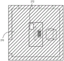
图2A-2G示出了可以由可见光传感器的相机记录的房间的示例图像。2A-2G illustrate example images of a room that may be recorded by a camera of a visible light sensor.

图3是示例可见光传感器的框图。3 is a block diagram of an example visible light sensor.

图4A和4B是用于基于由可见光传感器捕获的图像来控制负载控制设备的序列图。4A and 4B are sequence diagrams for controlling a load control device based on images captured by a visible light sensor.

图5示出了可以由可见光传感器执行的示例传感器事件过程的流程图。5 shows a flowchart of an example sensor event process that may be performed by a visible light sensor.

图6示出了可以由可见光传感器执行的示例占用/空置检测过程的流程图。6 shows a flow diagram of an example occupancy/vacancy detection process that may be performed by a visible light sensor.

图7示出了可以由可见光传感器执行的示例空置时间过程的流程图。7 shows a flowchart of an example idle time process that may be performed by a visible light sensor.

图8示出了用于生成和存储基线图像的示例基线配置过程的流程图。8 shows a flowchart of an example baseline configuration process for generating and storing baseline images.

图9A示出了用于确定由照明灯具发出的光对空间的子区域的影响的示例过程的流程图。9A shows a flowchart of an example process for determining the effect of light emitted by a lighting fixture on a sub-region of a space.

图9B-9E示出了应用了掩模的房间的示例夜间图像。9B-9E show example nighttime images of a room with a mask applied.

图10A示出了用于测量和控制任务区域或其他感兴趣区域上的照明水平的示例过程的流程图。10A shows a flowchart of an example process for measuring and controlling lighting levels on a task area or other area of interest.

图10B-10D示出了扣除和回填过程的示例图像。10B-10D show example images of the subtraction and backfill process.

图10E-10G示出了示例基线过程的示例图像。10E-10G show example images of example baseline procedures.

图11示出了用于测量和控制任务区域或其他感兴趣区域上的照明水平的另一示例过程的流程图。11 shows a flowchart of another example process for measuring and controlling lighting levels on a task area or other area of interest.

图12A和12B示出了用于控制照明灯具以在任务区域或其他感兴趣区域上提供均匀预定义光分布的示例过程的流程图。12A and 12B illustrate a flow diagram of an example process for controlling a lighting fixture to provide a uniform predefined light distribution over a task area or other area of interest.

图13示出了可以由可见光传感器和/或系统控制器执行的示例基线配置过程的流程图。13 shows a flowchart of an example baseline configuration process that may be performed by a visible light sensor and/or a system controller.

图14示出了用于基于图像控制相关色温(CTT)值的示例过程的流程图。14 shows a flowchart of an example process for controlling correlated color temperature (CTT) values based on an image.

图15示出了示例眩光检测和控制过程的流程图。15 shows a flowchart of an example glare detection and control process.

图16示出了另一示例眩光检测和控制过程的流程图。FIG. 16 shows a flowchart of another example glare detection and control process.

图17示出了可以被执行以配置可见光传感器和/或系统控制器以操作的示例配置过程的流程图。17 shows a flowchart of an example configuration process that may be performed to configure a visible light sensor and/or a system controller to operate.

图18示出了可以被执行以配置可见光传感器和/或系统控制器以操作的另一示例配置过程的流程图。18 illustrates a flowchart of another example configuration process that may be performed to configure a visible light sensor and/or a system controller for operation.

图19示出了可以被执行以自动地配置可见光传感器和/或系统控制器以操作的示例配置过程的流程图。19 shows a flowchart of an example configuration process that may be performed to automatically configure a visible light sensor and/or a system controller for operation.

图20示出了可以被执行以配置空间内的一个或多个区域的示例区域配置过程的流程图。20 shows a flowchart of an example region configuration process that may be performed to configure one or more regions within a space.

图21是示出示例网络设备的框图。21 is a block diagram illustrating an example network device.

图22是示出示例系统控制器的框图。22 is a block diagram illustrating an example system controller.

图23是示出示例控制目标设备的框图。FIG. 23 is a block diagram illustrating an example control target device.

具体实施方式Detailed ways

图1是用于控制从交流(AC)电源(未示出)输送到一个或多个电气负载的电量的示例负载控制系统100的简图。负载控制系统100可以被安装在建筑物的房间102中。负载控制系统100可以包括多个控制设备,该多个控制设备被配置成经由无线信号例如射频(RF)信号108彼此通信。替代地或附加地,负载控制系统100可以包括有线数字通信链路,其耦合到一个或多个控制设备,以提供负载控制设备之间的通信。负载控制系统100的控制设备可以包括多个控制源设备(例如,可操作用于响应于用户输入、占用/空置状况、测量的光强度的变化等来发送数字消息的输入设备)和多个控制目标设备(例如,可操作用于接收数字消息并且响应于所接收的数字消息来控制相应电气负载的负载控制设备)。负载控制系统100的单个控制设备可以操作为控制源和控制目标设备两者。1 is a schematic diagram of an example load control system 100 for controlling the amount of power delivered from an alternating current (AC) power source (not shown) to one or more electrical loads. The load control system 100 may be installed in a room 102 of a building. The load control system 100 may include a plurality of control devices configured to communicate with each other via wireless signals such as radio frequency (RF) signals 108 . Alternatively or additionally, the load control system 100 may include wired digital communication links coupled to one or more control devices to provide communication between the load control devices. The control devices of the load control system 100 may include a plurality of control source devices (eg, input devices operable to transmit digital messages in response to user input, occupancy/vacancy conditions, changes in measured light intensity, etc.) and a plurality of control A target device (eg, a load control device operable to receive digital messages and control respective electrical loads in response to the received digital messages). A single control device of the load control system 100 can operate as both a control source and a control target device.

控制源设备可以被配置成将数字消息直接发送到控制目标设备。另外,负载控制系统100可以包括系统控制器110(例如,中央处理器或负载控制器),该系统控制器110可操作用于将数字消息传送到控制设备(例如,控制源设备和/或控制目标设备)和从控制设备传送数字消息。例如,系统控制器110可以被配置成从控制源设备接收数字消息,并且响应于从控制源设备接收的数字消息,将数字消息发送到控制目标设备。控制源和控制目标设备以及系统控制器110可以被配置成使用诸如

Figure BDA0003503970120000101
协议的专有RF协议发送和接收RF信号108。替选地,可以使用诸如标准协议的不同的RF协议或不同的专有协议来发送RF信号108,标准协议例如是WIFI、ZIGBEE、Z-WAVE、KNX-RF、ENOCEAN RADIO协议之一。The control source device may be configured to send the digital message directly to the control target device. Additionally, the load control system 100 may include a system controller 110 (eg, a central processing unit or a load controller) operable to communicate digital messages to a control device (eg, a control source device and/or a control device) target device) and transmit digital messages from the control device. For example, the system controller 110 may be configured to receive a digital message from a control source device and transmit the digital message to a control target device in response to the digital message received from the control source device. The control source and control target devices and the system controller 110 may be configured to use devices such as
Figure BDA0003503970120000101
The protocol's proprietary RF protocol transmits and receives RF signals 108 . Alternatively, the RF signal 108 may be sent using a different RF protocol such as a standard protocol, eg one of WIFI, ZIGBEE, Z-WAVE, KNX-RF, ENOCEAN RADIO protocols, or a different proprietary protocol.

负载控制系统100可以包括一个或多个负载控制设备,例如,用于控制一个或多个照明灯具172、174、176、178的照明控制设备(例如,调光器开关、LED驱动器、镇流器等)。照明灯具172、174、176、178中的每一个可以包括照明负载(例如,发光二极管(LED)光源)和用于控制照明灯具的照明负载的相应照明控制设备(例如,LED驱动器)。The load control system 100 may include one or more load control devices, eg, lighting control devices (eg, dimmer switches, LED drivers, ballasts) for controlling one or more lighting fixtures 172 , 174 , 176 , 178 Wait). Each of the lighting fixtures 172, 174, 176, 178 may include a lighting load (eg, a light emitting diode (LED) light source) and a corresponding lighting control device (eg, an LED driver) for controlling the lighting load of the lighting fixture.

照明控制设备(例如,用于照明灯具172、174、176、178的LED驱动器)可以被配置成经由(例如,来自系统控制器110的)RF信号108无线地接收数字消息,并且响应于所接收的数字消息控制照明负载122。在2009年8月20日公开的、标题为COMMUNICATION SYSTEM FORA RADIO-FREQUENCY LOAD CONTROL SYSTEM的共同受让的美国专利申请公开No.2009/0206983中更详细地描述了可操作以发送和接收数字消息的照明控制设备的示例,其全部公开内容通过引用并入于此。Lighting control devices (eg, LED drivers for lighting fixtures 172, 174, 176, 178) may be configured to wirelessly receive digital messages via RF signals 108 (eg, from system controller 110), and respond to received digital messages The digital message controls the lighting load 122. A system operable to send and receive digital messages is described in more detail in commonly assigned US Patent Application Publication No. 2009/0206983, published August 20, 2009, and entitled COMMUNICATION SYSTEM FORA RADIO-FREQUENCY LOAD CONTROL SYSTEM. Examples of lighting control devices, the entire disclosures of which are incorporated herein by reference.

照明控制设备(例如,用于照明灯具172、174、176、178的LED驱动器)可以接收用于控制相应照明负载的色温的指令。在2014年10月23日公开的名为SYSTEMS AND METHODSFOR CONTROLLING COLOR TEMPERATURE的共同受让的美国专利申请公开No.2014/0312777中更详细地描述了配置成控制LED光源的色温的LED驱动器的示例,其全部公开内容通过引用并入于此。负载控制系统100可以进一步包括其他类型的远程定位的负载控制设备,诸如用于驱动荧光灯的电子调光镇流器。Lighting control devices (eg, LED drivers for lighting fixtures 172, 174, 176, 178) may receive instructions for controlling the color temperature of the respective lighting loads. An example of an LED driver configured to control the color temperature of an LED light source is described in more detail in commonly assigned US Patent Application Publication No. 2014/0312777, published October 23, 2014, entitled SYSTEMS AND METHODSFOR CONTROLLING COLOR TEMPERATURE, Its entire disclosure is incorporated herein by reference. The load control system 100 may further include other types of remotely located load control devices, such as electronic dimming ballasts for driving fluorescent lamps.

负载控制系统100可以包括用于控制插入式电气负载例如插入式照明负载(诸如落地灯142或台灯)和/或电器(诸如电视机或计算机监视器)的插入式负载控制设备140。例如,落地灯142可以被插入到插入式负载控制设备140中。插入式负载控制设备140可以被插入标准电气插座144中,并且因此可以串联耦合在AC电源和插入式照明负载之间。插入式负载控制设备140可以被配置成经由(例如,来自系统控制器110的)RF信号108接收数字消息,并且响应于所接收的数字消息来接通和断开或调节落地灯142的强度。The load control system 100 may include a plug-in load control device 140 for controlling plug-in electrical loads such as plug-in lighting loads (such as floor lamps 142 or desk lamps) and/or appliances (such as televisions or computer monitors). For example, a floor lamp 142 may be inserted into the plug-in load control device 140 . The plug-in load control device 140 can be plugged into a standard electrical outlet 144 and thus can be coupled in series between the AC power source and the plug-in lighting load. Plug-in load control device 140 may be configured to receive digital messages via RF signal 108 (eg, from system controller 110 ), and to turn on and off or adjust the intensity of floor lamps 142 in response to the received digital messages.

替代地或附加地,负载控制系统100可以包括用于控制插入到插座中的插入式电气负载的可控插座。负载控制系统100可以包括能够直接从系统控制器110接收无线信号108的一个或多个负载控制设备或电器,诸如扬声器146(例如,音频/视频或对讲系统的一部分),它能够产生可听见的声音,诸如警报、音乐、对讲功能等。Alternatively or additionally, the load control system 100 may include a controllable receptacle for controlling a plug-in electrical load inserted into the receptacle. Load control system 100 may include one or more load control devices or appliances capable of receiving wireless signals 108 directly from system controller 110, such as speakers 146 (eg, part of an audio/video or intercom system) capable of producing audible sound, such as alarms, music, intercom functions, etc.

负载控制系统100可以包括用于控制进入房间102的日光量的一个或多个日光控制设备,例如电动窗用品150,诸如电动蜂窝遮帘。每个电动窗用品150可以包括从顶轨154悬挂在相应窗104前方的窗用品织物152。每个电动窗用品150可以进一步包括位于顶轨154内部的电机驱动单元(未示出),用于升高和降低窗用品织物152以控制进入房间102的日光量。电动窗用品150的电机驱动单元可以被配置成经由(例如,来自系统控制器110的)RF信号108接收数字消息,并且响应于所接收的数字消息,调节相应的窗用品织物152的位置。负载控制系统100可以包括其他类型的日光控制设备,例如蜂窝遮帘、帐帘、罗马帘、百叶帘、波斯百叶窗、褶式百叶窗、张紧式卷帘系统、电致变色或智能窗和/或其他合适的日光控制设备。在2015年2月10日发布的名为MOTORIZED WINDOWTREATMENT的美国专利No.8,950,461和2014年10月16日公开的名为INTEGRATED ACCESSIBLE BATTERY COMPARTMENT FORMOTORIZED WINDOW TREATMENT的美国专利申请公开No.2014/0305602中更详细地描述了电池供电的电动窗用品的示例,其全部公开内容通过引用并入于此。The load control system 100 may include one or more daylight control devices for controlling the amount of daylight entering the room 102, such as a powered window appliance 150, such as a powered cellular shade. Each powered window covering 150 may include a window covering fabric 152 that hangs from a top rail 154 in front of the corresponding window 104 . Each powered window covering 150 may further include a motor drive unit (not shown) located inside the top rail 154 for raising and lowering the window covering fabric 152 to control the amount of sunlight entering the room 102 . The motor drive unit of the powered window covering 150 may be configured to receive digital messages via the RF signal 108 (eg, from the system controller 110 ) and adjust the position of the corresponding window covering fabric 152 in response to the received digital messages. The load control system 100 may include other types of daylight control devices such as cellular shades, drapery, Roman shades, venetian blinds, Persian blinds, pleated blinds, tensioned roller shutter systems, electrochromic or smart windows and/or Other suitable daylight control equipment. More details in US Patent No. 8,950,461, issued February 10, 2015, entitled MOTORIZED WINDOWTREATMENT, and US Patent Application Publication No. 2014/0305602, entitled INTEGRATED ACCESSIBLE BATTERY COMPARTMENT FORMOTORIZED WINDOW TREATMENT, published October 16, 2014 An example of a battery-operated power window appliance is described satisfactorily, the entire disclosure of which is incorporated herein by reference.

负载控制系统100可以包括一个或多个温度控制设备,例如,用于控制房间102中的室温的恒温器160。恒温器160可以经由控制链路(例如,模拟控制链路或有线数字通信链路)耦合到加热、通风和空调(HVAC)系统162。恒温器160可以被配置成与HVAC系统162的控制器无线地传送数字消息。恒温器160可以包括用于测量房间102的房间温度的温度传感器,并且可以控制HVAC系统162来将房间温度调节到设定点温度。负载控制系统100可以包括位于房间102中用于测量房间温度的一个或多个无线温度传感器(未示出)。HVAC系统162可以被配置成接通和断开压缩机以冷却房间102,并且响应于从恒温器160接收的控制信号,接通和断开加热房间的加热源。HVAC系统162可以被配置成响应于从恒温器160接收的控制信号来接通和断开HVAC系统的风扇。恒温器160和/或HVAC系统162可以被配置成控制一个或多个可控阻尼器来控制在房间102中的气流。恒温器160可以被配置成经由(例如,来自系统控制器110的)RF信号108接收数字消息,并且响应于所接收的数字消息来调节加热、通风和冷却。Load control system 100 may include one or more temperature control devices, such as thermostat 160 for controlling the room temperature in room 102 . Thermostat 160 may be coupled to heating, ventilation and air conditioning (HVAC) system 162 via a control link (eg, an analog control link or a wired digital communication link). Thermostat 160 may be configured to wirelessly communicate digital messages with a controller of HVAC system 162 . Thermostat 160 may include a temperature sensor for measuring the room temperature of room 102, and may control HVAC system 162 to regulate the room temperature to a set point temperature. Load control system 100 may include one or more wireless temperature sensors (not shown) located in room 102 for measuring room temperature. HVAC system 162 may be configured to turn compressors on and off to cool room 102 , and to turn on and off a heating source that heats the room in response to control signals received from thermostat 160 . The HVAC system 162 may be configured to turn the fans of the HVAC system on and off in response to control signals received from the thermostat 160 . Thermostat 160 and/or HVAC system 162 may be configured to control one or more controllable dampers to control airflow in room 102 . Thermostat 160 may be configured to receive digital messages via RF signal 108 (eg, from system controller 110 ), and to adjust heating, ventilation, and cooling in response to the received digital messages.

负载控制系统100可以包括一个或多个其他类型的负载控制设备,诸如:包括调光器电路和白炽灯或卤素灯的旋入式灯具;包括镇流器和紧凑型荧光灯的旋入式灯具;包括LED驱动器和LED光源的旋入式灯具;电气开关、可控断路器或用于接通和关闭电器的其他开关设备;可控电气插座或用于控制一个或多个插入式负载的可控电源板;用于控制诸如吊扇或排气风扇的电机负载的电机控制单元;用于控制投影屏幕的驱动单元;电动内部或外部百叶窗;空调;压缩机;电动底板加热器控制器;可变空气量控制器;新鲜空气进气控制器;通风控制器;为了与散热器和辐射加热系统一起使用的液压阀;湿度控制单元;加湿器;除湿器;热水器;锅炉控制器;池泵;冰箱;冰柜;电视机或计算机监视器;摄像机;音频系统或放大器;电梯;电源;发电机;充电器,诸如电动车辆充电器;替代能源控制器;和/或另一负载控制设备。The load control system 100 may include one or more other types of load control devices, such as: screw-in light fixtures including dimmer circuits and incandescent or halogen lamps; screw-in light fixtures including ballasts and compact fluorescent lamps; Screw-in luminaires including LED drivers and LED light sources; electrical switches, controllable circuit breakers or other switchgear for switching electrical appliances on and off; controllable electrical sockets or controllable electrical sockets for controlling one or more plug-in loads Power strips; motor control units for controlling motor loads such as ceiling fans or exhaust fans; drive units for controlling projection screens; electric interior or exterior blinds; air conditioners; compressors; electric floor heater controls; variable air volume controls; fresh air intake controls; ventilation controls; hydraulic valves for use with radiators and radiant heating systems; humidity control units; humidifiers; dehumidifiers; water heaters; boiler controls; pool pumps; refrigerators; A freezer; a television or computer monitor; a video camera; an audio system or amplifier; an elevator; a power source; a generator; a charger, such as an electric vehicle charger; an alternative energy controller; and/or another load control device.

负载控制系统100可以包括一个或多个输入设备,例如诸如遥控设备170和/或可见光传感器180。输入设备可以是固定的或可移动的输入设备。系统控制器110可以被配置成响应于从遥控设备170和/或可见光传感器180接收的数字消息,向负载控制设备(例如,照明灯具172、174、176、178、插入式负载控制设备140、电动窗用品150和/或恒温器160的照明控制设备)发送一个或多个数字消息。遥控设备170和/或可见光传感器180可以被配置成直接向照明灯具172、174、176、178的照明控制设备、插入式负载控制设备140、电动窗用品150和温度控制设备160发送数字消息。Load control system 100 may include one or more input devices, such as remote control device 170 and/or visible light sensor 180, for example. Input devices can be fixed or movable input devices. The system controller 110 may be configured to communicate to load control devices (eg, lighting fixtures 172 , 174 , 176 , 178 , plug-in load control devices 140 , electric The window treatments 150 and/or the lighting controls of the thermostat 160) send one or more digital messages. Remote control device 170 and/or visible light sensor 180 may be configured to send digital messages directly to lighting control devices, plug-in load control device 140 , power window appliance 150 , and temperature control device 160 of lighting fixtures 172 , 174 , 176 , 178 .

遥控设备170可以被配置成响应于遥控设备170的一个或多个按钮的致动,经由RF信号108向系统控制器110(例如,直接向系统控制器)发送数字消息。例如,遥控设备170可以是电池供电的。负载控制系统100可以包括其他类型的输入设备,诸如温度传感器、湿度传感器、辐射计、阴天传感器、阴影传感器、压力传感器、烟雾检测器、一氧化碳检测器、空气质量传感器、运动传感器、安全传感器、接近传感器、灯具传感器、隔断传感器、小键盘、多区域控制单元、滑块控制单元、动能或太阳能遥控器、钥匙链、蜂窝电话、智能电话、平板计算机、个人数字助理、个人计算机、膝上型计算机、时钟、视听控制器、安全设备、电力监视设备(例如,电力仪表、能量计、公用事业分表、公用事业费率计等)、中央控制发射器、住宅传感器、商业控制器、工业控制器和/或其任意组合。The remote control device 170 may be configured to transmit digital messages via the RF signal 108 to the system controller 110 (eg, directly to the system controller) in response to actuation of one or more buttons of the remote control device 170 . For example, the remote control device 170 may be battery powered. The load control system 100 may include other types of input devices, such as temperature sensors, humidity sensors, radiometers, cloudy sensors, shadow sensors, pressure sensors, smoke detectors, carbon monoxide detectors, air quality sensors, motion sensors, safety sensors, Proximity Sensors, Lighting Sensors, Partition Sensors, Keypads, Multi-Zone Control Units, Slider Control Units, Kinetic or Solar Remote Controls, Key Chains, Cell Phones, Smartphones, Tablets, Personal Digital Assistants, Personal Computers, Laptops Computers, clocks, audio visual controllers, security equipment, power monitoring equipment (e.g., power meters, energy meters, utility sub-meters, utility rate meters, etc.), central control transmitters, residential sensors, commercial controllers, industrial controls and/or any combination thereof.

系统控制器110可以耦合到网络,诸如无线或有线局域网(LAN),例如用于访问因特网。系统控制器110可以例如使用Wi-Fi技术无线连接到网络。系统控制器110可以经由网络通信总线(例如,以太网通信链路)耦合到网络。系统控制器110可以被配置成经由网络与例如诸如个人计算设备和/或可穿戴无线设备的移动设备190的一个或多个网络设备通信。移动设备190可以位于占用者192上,例如,可以附接到占用者的身体或衣服或可以由占用者手持。移动设备190可以由唯一标识移动设备190并且因此标识占用者192的唯一标识符(例如,存储在存储器中的序列号或地址)来表征。个人计算设备的示例可以包括智能电话(例如,

Figure BDA0003503970120000141
智能电话、
Figure BDA0003503970120000142
智能电话或
Figure BDA0003503970120000143
智能电话)、膝上型计算机和/或平板设备(例如,
Figure BDA0003503970120000144
手持计算设备)。可穿戴无线设备的示例可以包括活动追踪设备(诸如
Figure BDA0003503970120000145
设备、
Figure BDA0003503970120000146
设备和/或Sony
Figure BDA0003503970120000147
设备)、智能手表、智能服装(例如,
Figure BDA0003503970120000148
智能穿戴等)和/或智能眼镜(诸如Google
Figure BDA0003503970120000149
眼镜)。另外,系统控制器110可以被配置成经由网络与一个或多个其他控制系统(例如,建筑物管理系统、安全系统等)通信。System controller 110 may be coupled to a network, such as a wireless or wired local area network (LAN), for example, for accessing the Internet. The system controller 110 may connect wirelessly to the network, eg, using Wi-Fi technology. System controller 110 may be coupled to the network via a network communication bus (eg, an Ethernet communication link). The system controller 110 may be configured to communicate via a network with one or more network devices such as, for example, a mobile device 190 such as a personal computing device and/or a wearable wireless device. Mobile device 190 may be located on occupant 192, eg, may be attached to the occupant's body or clothing or may be held by the occupant. Mobile device 190 may be characterized by a unique identifier (eg, a serial number or address stored in memory) that uniquely identifies mobile device 190 and thus occupant 192 . Examples of personal computing devices may include smartphones (eg,
Figure BDA0003503970120000141
smartphone,
Figure BDA0003503970120000142
smartphone or
Figure BDA0003503970120000143
smartphones), laptops, and/or tablet devices (e.g.,
Figure BDA0003503970120000144
handheld computing devices). Examples of wearable wireless devices may include activity tracking devices such as
Figure BDA0003503970120000145
equipment,
Figure BDA0003503970120000146
device and/or Sony
Figure BDA0003503970120000147
devices), smart watches, smart clothing (e.g.,
Figure BDA0003503970120000148
smart wearables, etc.) and/or smart glasses (such as Google
Figure BDA0003503970120000149
Glasses). Additionally, the system controller 110 may be configured to communicate with one or more other control systems (eg, building management systems, security systems, etc.) via a network.

移动设备190可以被配置成例如在一个或多个因特网协议分组中,将数字消息发送到系统控制器110。例如,移动设备190可以被配置成通过LAN和/或经由因特网,向系统控制器110发送数字消息。移动设备190可以被配置成在因特网上将数字消息发送到外部服务(例如,If This Then That

Figure BDA00035039701200001410
服务),然后数字消息可以由系统控制器110接收。移动设备190可以经由Wi-Fi通信链路、Wi-MAX通信链路、蓝牙通信链路、近场通信(NFC)链路、蜂窝通信链路、电视白空间(TVWS)通信链路或其任意组合来发送和接收RF信号109以与例如系统控制器通信。替代地或附加地,移动设备190可以被配置成根据专有协议来发送RF信号。负载控制系统100可以包括耦合到网络的其他类型的网络设备,诸如桌面型个人计算机、Wi-Fi或者具有无线通信能力的电视机或者任何其它合适的支持因特网协议的设备。在2013年1月31日公开的名为LOAD CONTROL DEVICE HAVING INTERNET CONNECTIVITY的共同受让的美国专利申请公开No.2013/0030589中更详细地描述了可操作用于与网络上的移动和/或网络设备通信的负载控制系统的示例,其全部公开内容通过引用并入于此。Mobile device 190 may be configured to send digital messages to system controller 110, eg, in one or more Internet Protocol packets. For example, mobile device 190 may be configured to send digital messages to system controller 110 over a LAN and/or via the Internet. Mobile device 190 may be configured to send digital messages over the Internet to external services (eg, If This Then That
Figure BDA00035039701200001410
service), the digital message may then be received by the system controller 110. The mobile device 190 may communicate via a Wi-Fi communication link, a Wi-MAX communication link, a Bluetooth communication link, a near field communication (NFC) link, a cellular communication link, a television white space (TVWS) communication link, or any RF signals 109 are sent and received in combination to communicate with, for example, a system controller. Alternatively or additionally, the mobile device 190 may be configured to transmit RF signals according to a proprietary protocol. Load control system 100 may include other types of network devices coupled to the network, such as desktop personal computers, Wi-Fi or televisions with wireless communication capabilities, or any other suitable Internet Protocol enabled device. Mobility and/or network operations operable to communicate with Example of a load control system for device communication, the entire disclosure of which is incorporated herein by reference.

系统控制器110可以被配置成确定移动设备190和/或占用者192的位置。系统控制器110可以被配置成响应于确定移动设备190和/或占用者192的位置,控制(例如,自动地控制)负载控制设备(例如,照明灯具172、174、176、178的照明控制设备、插入式负载控制设备140、电动窗用品150和/或温度控制设备160)。System controller 110 may be configured to determine the location of mobile device 190 and/or occupant 192 . System controller 110 may be configured to control (eg, automatically control) the lighting control devices of load control devices (eg, lighting fixtures 172 , 174 , 176 , 178 ) in response to determining the location of mobile device 190 and/or occupant 192 , plug-in load control device 140, power window appliance 150 and/or temperature control device 160).

负载控制系统100的一个或多个控制设备可以发送信标信号,例如使用诸如

Figure BDA0003503970120000151
技术的近距离和/或低功率RF技术发送的RF信标信号。负载控制系统100还可以包括用于发送信标信号的至少一个信标发送设备194。移动设备190可以被配置成当位于当前正在发送信标信号的控制设备附近时接收信标信号。信标信号可以包括识别发送信标信号的负载控制设备的位置的唯一标识符。由于可以使用近距离和/或低功率技术来发送信标信号,因此唯一标识符可以指示移动设备190的大致位置。移动设备190可以被配置成将唯一标识符发送给系统控制器110,其可被配置成使用唯一标识符(例如,使用存储在存储器中或经由因特网检索的数据)来确定移动设备190的位置。在2016年2月25日公开的名为LOAD CONTROL SYSTEMRESPONSIVE TO LOCATION OF AN OCCUPANT AND MOBILEDEVICES的共同受让的美国专利申请公开No.2016/0056629中更详细地描述了用于响应于建筑物内的移动设备和/或占用者的位置来控制一个或多个电气负载的负载控制系统的示例,其全部公开内容通过引用并入于此。One or more control devices of the load control system 100 may transmit a beacon signal, eg, using a system such as
Figure BDA0003503970120000151
RF beacon signals transmitted by technology's short-range and/or low-power RF technologies. The load control system 100 may also include at least one beacon transmitting device 194 for transmitting beacon signals. The mobile device 190 may be configured to receive a beacon signal when located in the vicinity of a control device that is currently transmitting the beacon signal. The beacon signal may include a unique identifier that identifies the location of the load control device transmitting the beacon signal. Since the beacon signal may be transmitted using short range and/or low power techniques, the unique identifier may indicate the approximate location of the mobile device 190 . Mobile device 190 may be configured to send the unique identifier to system controller 110, which may be configured to use the unique identifier (eg, using data stored in memory or retrieved via the Internet) to determine the location of mobile device 190. A method for responding to movement within a building is described in more detail in commonly assigned US Patent Application Publication No. 2016/0056629, published February 25, 2016, entitled LOAD CONTROL SYSTEMRESPONSIVE TO LOCATION OF AN OCCUPANT AND MOBILEDEVICES An example of a load control system in which the location of equipment and/or occupants controls one or more electrical loads, the entire disclosure of which is incorporated herein by reference.

可见光传感器180可以包括被转向到房间102中的相机,并且可以被配置成记录房间102的图像(例如静态图像和/或视频)。例如,可见光传感器180可以被安装到房间102的天花板和/或可以被安装到房间的墙上(如图1所示)。可见光传感器180可以包括鱼眼透镜。如果可见光传感器180被安装到天花板,则由相机记录的图像可以是房间102的俯视图。Visible light sensor 180 may include a camera steered into room 102 and may be configured to record images (eg, still images and/or video) of room 102 . For example, visible light sensor 180 may be mounted to the ceiling of room 102 and/or may be mounted to the wall of the room (as shown in FIG. 1 ). The visible light sensor 180 may include a fisheye lens. If the visible light sensor 180 is mounted to the ceiling, the image recorded by the camera may be a top view of the room 102 .

图2A-2G示出了可以由可见光传感器的相机记录的房间200的简化示例图像。如图2A所示,房间200可以包括房间特征。房间特征可以包括具有门口212和窗214的墙壁210。房间200可以包括书桌220,计算机监视器222和键盘224可以位于书桌220上。房间200还可以包括椅子226,房间200的占用者通常可以坐在该椅子上以使用计算机监视器222和小键盘224。为了信息的目的而提供图2A-2G中所示的房间200的示例图像,并且其可能与由可见光传感器180捕获的实际图像不相同。由于可见光传感器180可以具有鱼眼透镜,因此相机捕获的实际图像可能使图像扭曲并且可能不是如图2A-2G所示的实际的二维图像。另外,图2A-2G所示的房间200的示例图像示出具有厚度的墙壁210,并且由可见光传感器180捕获的实际图像可以示出房间102的内表面。2A-2G show simplified example images of a room 200 that may be recorded by a camera of a visible light sensor. As shown in FIG. 2A, room 200 may include room features. Room features may include walls 210 with doorways 212 and windows 214 . Room 200 may include desk 220 on which computer monitor 222 and keyboard 224 may be located. Room 200 may also include a chair 226 on which an occupant of room 200 may typically sit to use computer monitor 222 and keypad 224 . The example images of room 200 shown in FIGS. 2A-2G are provided for informational purposes and may not be the same as the actual images captured by visible light sensor 180 . Since the visible light sensor 180 may have a fisheye lens, the actual image captured by the camera may distort the image and may not be an actual two-dimensional image as shown in Figures 2A-2G. Additionally, the example images of room 200 shown in FIGS. 2A-2G show walls 210 having thickness, and the actual image captured by visible light sensor 180 may show the interior surfaces of room 102 .

再参考图1,可见光传感器180可以被配置成处理由相机记录的图像,并且响应于所处理的图像,向负载控制设备发送一个或多个消息(例如,数字消息)。可见光传感器180可以被配置成从图像检测空间(例如,房间102和/或房间200)的一个或多个环境特性。例如,可见光传感器180的控制电路可以被配置成评估图像并且确定图像中描绘的房间(例如,房间102)内的一个或多个环境特性。Referring again to FIG. 1 , the visible light sensor 180 may be configured to process images recorded by the camera and, in response to the processed images, send one or more messages (eg, digital messages) to the load control device. Visible light sensor 180 may be configured to detect one or more environmental characteristics of a space (eg, room 102 and/or room 200 ) from images. For example, the control circuitry of visible light sensor 180 may be configured to evaluate the image and determine one or more environmental characteristics within a room (eg, room 102 ) depicted in the image.

环境特性可以包括图像的一个或多个细节,诸如在图像中描绘的移动、照明强度(例如,来自阳光196和/或人造光的照明强度)、色温、占用和/或空置状况等。照明强度可以包括照明控制设备输出的光的百分比。如本文所述,照明强度可以包括来自阳光196的照明强度、人造光、照明控制设备输出的光的百分比、反射光、亮度和/或照度。亮度可以包括从一个或多个表面反射的光量和/或可以指示可以由可见光传感器感知的光功率。照度可以包括落在一个或多个表面区域上和/或在一个或多个表面区域上扩散的光量。亮度可以是可测量的量。可见光传感器180可以基于(例如,使用校正因子)测量的亮度来确定照度。亮度和照度可以与照明灯具的照明强度相关。例如,调节照明灯具的照明强度可以影响照度(例如,落在一个或多个表面区域上和/或在一个或多个表面区域上扩散的光量)的量(例如,可测量的量)。随着照度的量变化,亮度可能改变。Environmental characteristics may include one or more details of the image, such as movement depicted in the image, lighting intensity (eg, from sunlight 196 and/or artificial light), color temperature, occupancy and/or vacancy conditions, and the like. The lighting intensity may include the percentage of light output by the lighting control device. As described herein, illumination intensity may include illumination intensity from sunlight 196, artificial light, percentage of light output by the lighting control device, reflected light, brightness, and/or illuminance. Brightness can include the amount of light reflected from one or more surfaces and/or can be indicative of light power that can be sensed by a visible light sensor. Illuminance may include the amount of light that falls on and/or spreads over one or more surface areas. Brightness can be a measurable quantity. Visible light sensor 180 may determine illuminance based on the measured luminance (eg, using a correction factor). Brightness and illuminance can be related to the lighting intensity of the lighting fixture. For example, adjusting the illumination intensity of a lighting fixture may affect the amount (eg, a measurable amount) of illuminance (eg, the amount of light falling on and/or diffused over one or more surface areas). As the amount of illuminance changes, the brightness may change.

可见光传感器180可以被配置成使用一个或多个算法或图像分析技术来确定房间内的环境特性。例如,可见光传感器180可以被配置成使用背景扣除和/或背景维护来确定房间内的环境特性。可见光传感器180可以使用背景扣除来检测在图像内改变的对象。例如,背景扣除可以被用于检测图像内的移动和/或用于检测图像内的占用/空置状况。背景维护可以被用于执行背景扣除。可以被用于执行背景维护的示例算法可以包括相邻帧差异算法、均值和阈值算法、均值和协方差算法、高斯算法的混合、归一化块相关算法以及其他算法。可见光传感器180还可以或替选地将图像提供给系统控制器110或另一计算设备,用于执行成像分析以确定环境特性和/或控制电气负载/负载控制设备,如本文所述。Visible light sensor 180 may be configured to determine environmental characteristics within the room using one or more algorithms or image analysis techniques. For example, visible light sensor 180 may be configured to use background subtraction and/or background maintenance to determine environmental characteristics within a room. The visible light sensor 180 may use background subtraction to detect objects that change within the image. For example, background subtraction may be used to detect movement within the image and/or to detect occupancy/vacancy conditions within the image. Background maintenance can be used to perform background subtraction. Example algorithms that may be used to perform background maintenance may include adjacent frame difference algorithms, mean and threshold algorithms, mean and covariance algorithms, mixtures of Gaussian algorithms, normalized block correlation algorithms, and others. Visible light sensor 180 may also or alternatively provide images to system controller 110 or another computing device for use in performing imaging analysis to determine environmental characteristics and/or control electrical loads/load control devices, as described herein.

可见光传感器180可以包括用于发送和接收RF和/或有线信号的通信电路。例如,可见光传感器180可以包括用于发送和接收RF信号108和/或RF信号109的通信电路。可见光传感器180可以被配置成处理由相机记录的一个或多个图像并且将数字消息发送到负载控制设备和/或系统控制器110。数字消息可以包括用于控制相应负载控制设备处的电气负载的控制指令。数字消息还可以或替选地包括在图像中识别的环境特性的指示,可以由这些指示生成控制指令以控制负载控制设备处的电气负载。可见光传感器180可以周期性地和/或基于另一触发事件,将数字消息发送到负载控制设备和/或系统控制器。可见光传感器180可以响应于一个或多个图像的特征(例如,响应于从图像确定的一个或多个环境特性),将数字消息发送到负载控制设备。例如,可见光传感器180可以被配置成使用相机,检测房间102中的移动、照明强度(例如,来自阳光196和/或人造光的照明强度)、色温和/或占用/空置状况。可见光传感器180可以响应于检测到移动、照明强度(例如,来自阳光196和/或人造光的照明强度)、色温和/或占用/空置状况,经由RF信号108(例如,使用专有协议),将数字消息发送到负载控制设备和/或系统控制器110。Visible light sensor 180 may include communication circuitry for sending and receiving RF and/or wired signals. For example, visible light sensor 180 may include communication circuitry for sending and receiving RF signal 108 and/or RF signal 109 . The visible light sensor 180 may be configured to process one or more images recorded by the camera and send digital messages to the load control device and/or the system controller 110 . The digital messages may include control instructions for controlling the electrical loads at the respective load control devices. The digital message may also or alternatively include indications of environmental characteristics identified in the image from which control instructions may be generated to control electrical loads at the load control device. The visible light sensor 180 may send a digital message to the load control device and/or the system controller periodically and/or based on another trigger event. The visible light sensor 180 may transmit a digital message to the load control device in response to one or more characteristics of the image (eg, in response to one or more environmental characteristics determined from the image). For example, visible light sensor 180 may be configured to use a camera to detect movement in room 102, lighting intensity (eg, from sunlight 196 and/or artificial light), color temperature and/or occupancy/vacancy conditions. Visible light sensor 180 may, via RF signal 108 (eg, using a proprietary protocol), respond to detection of movement, illumination intensity (eg, from sunlight 196 and/or artificial light), color temperature and/or occupancy/vacancy conditions, The digital message is sent to the load control device and/or the system controller 110 .

可见光传感器180可以操作以配置和/或控制负载控制系统100。可见光传感器180可以生成图像并且识别和/或定义图像中的对象,以便能够控制负载控制系统中的设备。可见光传感器180可以从图像中的对象识别移动、光强度、色温、占用/空置状况。负载控制系统100可以根据定义的对象、移动、光强度、色温、占用/空置状况以及在其上定义的规则来配置。The visible light sensor 180 is operable to configure and/or control the load control system 100 . The visible light sensor 180 can generate images and identify and/or define objects in the images so that devices in the load control system can be controlled. The visible light sensor 180 can identify movement, light intensity, color temperature, occupancy/vacancy conditions from objects in the image. The load control system 100 can be configured according to defined objects, movement, light intensity, color temperature, occupancy/vacancy conditions, and rules defined thereon.

可见光传感器180可以被配置成以一个或多个传感器模式(例如,占用和/或空置传感器模式、采光传感器模式、颜色传感器模式、日光眩光检测传感器模式、占用者计数传感器模式等)操作。可见光传感器180可以执行不同的算法来处理每个传感器模式中的图像以确定将发送到负载控制设备的数据。可见光传感器180可以响应于图像,经由RF信号108(例如,使用专有协议)发送数字消息。可见光传感器180可以将数字消息(例如控制指令)直接发送到负载控制设备和/或系统控制器110,然后系统控制器110可以将消息传送到负载控制设备。可见光传感器180可以包括用于使用专有协议发送和/或接收RF信号108的第一通信电路。Visible light sensor 180 may be configured to operate in one or more sensor modes (eg, occupancy and/or vacancy sensor mode, daylight sensor mode, color sensor mode, daylight glare detection sensor mode, occupant count sensor mode, etc.). The visible light sensor 180 may execute different algorithms to process the images in each sensor mode to determine the data to send to the load control device. The visible light sensor 180 may transmit a digital message via the RF signal 108 (eg, using a proprietary protocol) in response to the image. The visible light sensor 180 may send digital messages (eg, control instructions) directly to the load control device and/or the system controller 110, which may then transmit the message to the load control device. The visible light sensor 180 may include a first communication circuit for sending and/or receiving the RF signal 108 using a proprietary protocol.

用户192可以配置可见光传感器180以根据日光眩光传感器模式、采光传感器模式、颜色传感器模式、占用/空置传感器模式和/或占用者计数传感器模式,在房间102内执行动作。用户192可以配置可见光传感器180以在房间102内的一个或多个感兴趣区域内,根据日光眩光传感器模式、采光传感器模式、颜色传感器模式、占用/空置传感器模式和/或占用者计数传感器模式执行动作。例如,用户192可以配置可见光传感器180,以基于用户192进入房间102、离开房间102,和/或驻留在房间102内,将总照明强度(例如,人造光和/或阳光196)设置为任务区域的优选总照度。用户192可以附加地或替选地配置可见光传感器180,以基于用户192进入房间102、离开房间102,和/或驻留在房间102内,将色温设置为优选的色温。可见光传感器180可以在不同模式下在房间102内应用一个或多个数字掩模。每个传感器模式可以具有当可见光传感器180在相应模式下操作时的不同的掩模。User 192 may configure visible light sensor 180 to perform actions within room 102 according to a daylight glare sensor mode, daylight sensor mode, color sensor mode, occupancy/vacancy sensor mode, and/or occupant count sensor mode. User 192 may configure visible light sensor 180 to perform within one or more regions of interest within room 102 according to a solar glare sensor mode, daylighting sensor mode, color sensor mode, occupancy/vacancy sensor mode, and/or occupant count sensor mode action. For example, user 192 may configure visible light sensor 180 to set the total lighting intensity (eg, artificial light and/or sunlight 196 ) as a task based on user 192 entering room 102 , leaving room 102 , and/or staying in room 102 The preferred total illuminance of the area. User 192 may additionally or alternatively configure visible light sensor 180 to set the color temperature to a preferred color temperature based on user 192 entering room 102 , leaving room 102 , and/or staying in room 102 . Visible light sensor 180 may apply one or more digital masks within room 102 in different modes. Each sensor mode may have a different mask when the visible light sensor 180 is operating in the corresponding mode.

可见光传感器180可以被配置成执行多个传感器事件以检测空间的各种环境特性。例如,为了执行传感器事件,可见光传感器180可以被配置成在一个或多个传感器模式下操作。每个传感器模式在被执行时,可以检测一个或多个传感器事件。可以使用识别图像中的一个或多个环境特性的算法来检测传感器事件。例如,在占用/空置传感器模式中,传感器事件可以包括用户进入房间的门口、在房间的预定义区域内检测到的移动,或者可以由空间的环境特性检测的另一占用/空置传感器事件。另外,可见光传感器180可以被配置成从存储器获得某些预先配置的控制参数(例如,灵敏度、基线值、阈值、界限值等),其可以由算法使用来在传感器事件期间检测环境特性。The visible light sensor 180 may be configured to perform multiple sensor events to detect various environmental characteristics of the space. For example, to perform sensor events, visible light sensor 180 may be configured to operate in one or more sensor modes. Each sensor mode, when executed, can detect one or more sensor events. Sensor events may be detected using algorithms that identify one or more environmental characteristics in an image. For example, in an occupancy/vacancy sensor mode, a sensor event may include a user entering a doorway to a room, a detected movement within a predefined area of the room, or another occupancy/vacancy sensor event that may be detected by environmental characteristics of the space. Additionally, visible light sensor 180 may be configured to obtain certain preconfigured control parameters (eg, sensitivity, baseline values, thresholds, limit values, etc.) from memory that may be used by algorithms to detect environmental characteristics during sensor events.

可见光传感器180可以被配置成在处理图像时聚焦在由相机记录的图像中的一个或多个感兴趣区域上,以在传感器事件期间检测环境特性。例如,可以掩蔽(例如,数字掩蔽)由相机记录的图像的某些区域,使得可见光传感器180可以不处理掩蔽区域中的图像部分。当在图像的未掩蔽部分中识别出传感器事件的某些环境特性时,可以触发控制策略。控制策略可以是用于基于所检测的环境特性执行一个或多个负载控制设备的控制(例如,生成控制指令)的算法。The visible light sensor 180 may be configured to focus on one or more regions of interest in an image recorded by the camera when processing the image to detect environmental characteristics during a sensor event. For example, certain areas of the image recorded by the camera may be masked (eg, digitally masked) such that visible light sensor 180 may not process portions of the image in the masked areas. Control strategies can be triggered when certain environmental characteristics of sensor events are identified in unmasked portions of the image. A control strategy may be an algorithm for performing control (eg, generating control instructions) of one or more load control devices based on detected environmental characteristics.

感兴趣区域可以是房间102内、与房间102内的环境特性相关的区域。例如,感兴趣区域可以是门105(例如,或其他房间特征)、用户任务区域(例如,书桌106、监视器166和/或键盘168)、从门105到用户任务区域的用户路径等。可见光传感器180可以被配置成确定出现在感兴趣区域的一个或多个环境特性。例如,可见光传感器180可以被配置成确定用户任务区域处的照明强度。可见光传感器180可以确定用户任务区域处的照明强度,例如,以确定出现在任务区域处的照明强度是否是优选的照明强度。作为另一示例,可见光传感器180可以被配置成确定从门105到用户任务区域的路径处的占用/空置状况。可见光传感器可以被配置成基于用户192是进入房间102、离开房间102还是驻留在房间102内,确定占用/空置状况以调节控制设备(例如,照明灯具172、174、176、178)。A region of interest may be an area within room 102 that is related to environmental characteristics within room 102 . For example, the area of interest may be a door 105 (eg, or other room feature), a user task area (eg, desk 106, monitor 166, and/or keyboard 168), a user path from door 105 to the user task area, and the like. The visible light sensor 180 may be configured to determine one or more environmental characteristics present in the region of interest. For example, visible light sensor 180 may be configured to determine the intensity of lighting at the user's task area. The visible light sensor 180 may determine the lighting intensity at the user's task area, eg, to determine whether the lighting intensity present at the task area is a preferred lighting intensity. As another example, visible light sensor 180 may be configured to determine occupancy/vacancy conditions at the path from door 105 to the user task area. Visible light sensors may be configured to determine occupancy/vacancy conditions to adjust control devices (eg, lighting fixtures 172 , 174 , 176 , 178 ) based on whether user 192 enters room 102 , leaves room 102 , or resides in room 102 .

可见光传感器180可以被配置成在房间102内提供掩模(例如,数字掩模)。可见光传感器180可以被配置成应用掩模(例如,可以存储在存储器中的预定数字掩模)以聚焦在特定的感兴趣区域上,并且处理感兴趣区域中的图像部分。另外,可见光传感器180可以被配置成同时聚焦在图像中的多个感兴趣区域上(例如,如图2B-2G所示)。例如,可见光传感器180可以在房间102中的门105上提供掩模。在门105被掩蔽的情况下,可见光传感器180可以忽略门105和/或位于门105处的移动。如果房间102的一部分被掩蔽,可见光传感器180可以聚焦在一个或多个感兴趣区域上。例如,如果门105被掩蔽,则可见光传感器180可以聚焦在用户任务区域上,诸如书桌106、监视器166和键盘168(例如,未被掩蔽的用户区域)。可以对每个传感器事件定义特定掩模。Visible light sensor 180 may be configured to provide a mask (eg, a digital mask) within room 102 . The visible light sensor 180 may be configured to apply a mask (eg, a predetermined digital mask that may be stored in memory) to focus on a particular region of interest, and to process the portion of the image in the region of interest. Additionally, visible light sensor 180 may be configured to focus simultaneously on multiple regions of interest in the image (eg, as shown in Figures 2B-2G). For example, visible light sensor 180 may provide a mask on door 105 in room 102 . In the event that the door 105 is masked, the visible light sensor 180 may ignore the door 105 and/or movement at the door 105 . If a portion of room 102 is masked, visible light sensor 180 may be focused on one or more regions of interest. For example, if door 105 is masked, visible light sensor 180 may be focused on user task areas such as desk 106, monitor 166, and keyboard 168 (eg, unmasked user areas). Specific masks can be defined for each sensor event.

可以执行图像处理(例如,数字图像处理)以数字地掩蔽房间102的一个或多个部分。例如,图像处理可以通过选择可见光传感器180的处理可能或可能不会发生的图像内的一组像素来数字地掩蔽房间102的一个或多个部分。可见光传感器180可以通过忽略表示将被数字掩蔽的房间102的部分的图像的一个或多个像素来记录房间102的图像并且数字地掩蔽房间102的一部分(例如,门105)。Image processing (eg, digital image processing) may be performed to digitally mask one or more portions of room 102 . For example, image processing may digitally mask one or more portions of room 102 by selecting a set of pixels within the image where processing of visible light sensor 180 may or may not occur. Visible light sensor 180 may record an image of room 102 and digitally mask a portion of room 102 (eg, door 105 ) by ignoring one or more pixels representing the image of the portion of room 102 to be digitally masked.

掩模可以被用于忽略对控制负载控制系统100不太相关或一段时间内不太相关的空间的部分(例如,房间102)。例如,掩模可以被用于忽略房间的一些部分(例如,房间102内的门105和/或房间102中的内部窗)以阻止在房间102外发生的活动(例如,在房间102附近的走廊中行走和/或照明)。可见光传感器180可以通过忽略描绘门105附近的对象和/或活动的房间102的像素来掩蔽房间102内的门105和/或房间102中的内部窗。A mask may be used to ignore portions of a space (eg, room 102 ) that are less relevant to controlling the load control system 100 or less relevant over time. For example, a mask may be used to ignore parts of a room (eg, doors 105 in room 102 and/or interior windows in room 102 ) to prevent activity that occurs outside of room 102 (eg, in a hallway near room 102 ) walking and/or lighting). Visible light sensor 180 may mask doors 105 within room 102 and/or interior windows in room 102 by ignoring pixels depicting objects near door 105 and/or active room 102 .

掩模可以被用于忽略房间102内的一个或多个对象。例如,可以使用掩模来忽略除了房间102内的门105之外的房间的部分。可以监视门105以识别占用状况。例如,可见光传感器180可以被配置成通过识别用户步入和/或离开房间102的门105来监视占用状况。可见光传感器180可以根据占用状况来控制负载控制系统100。当确定房间102中的占用/空置状况时,可见光传感器180可能对掩蔽区域中的移动和/或用户没有响应。可见光传感器180可以被配置成如果房间102的一部分内的移动和/或用户与负载控制系统100无关,排除检测的房间102的一个或多个部分内的运动。Masks may be used to ignore one or more objects within room 102 . For example, a mask may be used to ignore parts of the room other than door 105 within room 102 . Door 105 can be monitored to identify occupancy conditions. For example, visible light sensor 180 may be configured to monitor occupancy by identifying door 105 through which a user enters and/or exits room 102 . The visible light sensor 180 may control the load control system 100 according to occupancy conditions. When determining occupancy/vacancy conditions in room 102, visible light sensor 180 may not be responsive to movement and/or users in the masked area. Visible light sensor 180 may be configured to exclude motion within one or more portions of room 102 from being detected if movement within a portion of room 102 and/or the user is not associated with load control system 100 .

可见光传感器180可以被配置成在传感器模式之间动态地改变、将数字掩模应用于图像,以及根据当前传感器事件控制参数。例如,可见光传感器180可以被配置成在操作期间顺序地和/或周期性地逐步通过不同的传感器模式(例如,占用/空置传感器模式、采光传感器模式、颜色传感器模式、日光眩光传感器模式、占用者计数模式等)。每个传感器事件可以由传感器模式(例如,指定要使用的算法)、一个或多个控制参数和/或一个或多个数字掩模来表征。当在图像的未掩蔽区域中识别出环境特性时,可以在传感器模式期间检测传感器事件。The visible light sensor 180 may be configured to dynamically change between sensor modes, apply a digital mask to the image, and control parameters based on current sensor events. For example, visible light sensor 180 may be configured to sequentially and/or periodically step through different sensor modes during operation (eg, occupancy/vacancy sensor mode, daylight sensor mode, color sensor mode, daylight glare sensor mode, occupant count mode, etc.). Each sensor event may be characterized by a sensor mode (eg, specifying an algorithm to use), one or more control parameters, and/or one or more digital masks. Sensor events can be detected during sensor mode when environmental features are identified in unmasked areas of the image.

可见光传感器180可以被配置成在一段时间期满之后的操作期间循环通过不同的传感器模式(例如,经由循环技术,诸如在返回到该序列的第一传感器模式前,对序列中的每个传感器模式赋予预定义时间量)。可见光传感器180可以被配置成根据从图像识别的当前环境特性或者从图像识别的环境特性的变化来改变其传感器模式。例如,可见光传感器180可以被配置成根据用户移动、房间102内的光水平、房间102外的日光水平、色温、日光眩光等来改变其传感器模式。可见光传感器180可以被配置成根据占用/空置状况来改变其传感器模式。例如,如果房间102是空的,则可见光传感器180可以在占用/空置传感器模式下操作,并且在空置状况期间不可以使用其他传感器模式。可以根据例如在可见光传感器180的配置期间定义的优先级集合,组织传感器模式。Visible light sensor 180 may be configured to cycle through different sensor modes during operation after a period of time has expired (eg, via a looping technique, such as for each sensor mode in the sequence before returning to the first sensor mode of the sequence. given a predefined amount of time). The visible light sensor 180 may be configured to change its sensor mode according to a current environmental characteristic identified from the image or a change in the environmental characteristic identified from the image. For example, visible light sensor 180 may be configured to change its sensor mode based on user movement, light levels within room 102, sunlight levels outside room 102, color temperature, sunlight glare, and the like. The visible light sensor 180 may be configured to change its sensor mode according to occupancy/vacancy conditions. For example, if room 102 is empty, visible light sensor 180 may operate in an occupancy/vacancy sensor mode, and no other sensor modes may be used during the vacancy condition. The sensor modes may be organized according to, for example, a set of priorities defined during configuration of the visible light sensor 180 .

可见光传感器180可以将不同的掩模应用于房间102的部分。不同的掩模可以在不同的操作模式期间操作或者与用于执行控制的不同对象相关。不同的掩模可以在相同的传感器模式期间操作或者与用于执行控制的相同的对象相关。例如,可见光传感器180可以被配置成通过将第一掩模应用于除第一感兴趣区域之外的对象来识别第一感兴趣区域的环境特性。第一掩模可以允许可见光传感器例如聚焦在第一感兴趣区域上并且检测第一感兴趣区域内的颜色强度。可见光传感器180可以被配置成通过应用第二掩模来忽略第二感兴趣区域的环境特性以忽略除第二感兴趣区域以外的对象。例如,第二掩模可以与忽略除了第二感兴趣区域之外的区域中的移动相关。可见光传感器180可以被配置成应用第一掩模以聚焦在图像的第一感兴趣区域上,以便检测第一感兴趣区域中的移动、色温、占用/空置状况等中的至少一个。可见光传感器180可以被配置成应用第二掩模以忽略图像的第二感兴趣区域以忽略第二感兴趣区域中的照明强度、色温、占用/空置状况等。Visible light sensor 180 may apply different masks to portions of room 102 . Different masks may operate during different operating modes or be associated with different objects for performing control. Different masks may operate during the same sensor mode or be associated with the same object used to perform control. For example, the visible light sensor 180 may be configured to identify environmental characteristics of the first region of interest by applying the first mask to objects other than the first region of interest. The first mask may allow the visible light sensor, eg, to focus on the first region of interest and detect color intensity within the first region of interest. The visible light sensor 180 may be configured to ignore the environmental characteristics of the second region of interest by applying a second mask to ignore objects other than the second region of interest. For example, the second mask may be associated with ignoring movement in regions other than the second region of interest. The visible light sensor 180 may be configured to apply a first mask to focus on a first region of interest of the image in order to detect at least one of movement, color temperature, occupancy/vacancy conditions, etc. in the first region of interest. The visible light sensor 180 may be configured to apply a second mask to ignore the second region of interest of the image to ignore illumination intensity, color temperature, occupancy/vacancy conditions, etc. in the second region of interest.

第一感兴趣区域可以是用户执行任务的区域,诸如用户的任务区域。例如,第一感兴趣区域可以包括用户的书桌106、监视器166和/或键盘168。第二感兴趣区域可以是用户执行任务的区域,或者第二感兴趣区域可以是与用户执行任务无关的控制区域。例如,第二感兴趣区域可以是门口105、窗104和/或其中控制电路将忽略移动、照明强度(例如,来自阳光196和/或人造光的照明强度)、色温和/或占用/空置状况的空间内的另一个位置。可见光传感器180可以被配置成将第一掩模应用于第一感兴趣区域(例如,用户的书桌106、监视器166和/或键盘168)和/或可见光传感器180可以被配置成将第二掩模应用于第二感兴趣区域(例如,门口108、窗104)。The first area of interest may be an area in which the user performs a task, such as the user's task area. For example, the first region of interest may include the user's desk 106 , monitor 166 and/or keyboard 168 . The second area of interest may be an area in which the user performs a task, or the second area of interest may be a control area unrelated to the user's performance of the task. For example, the second region of interest may be doorway 105, window 104 and/or where the control circuitry will ignore movement, lighting intensity (eg, from sunlight 196 and/or artificial light), color temperature and/or occupancy/vacancy conditions another location within the space. Visible light sensor 180 may be configured to apply a first mask to a first region of interest (eg, user's desk 106, monitor 166, and/or keyboard 168) and/or visible light sensor 180 may be configured to apply a second mask to a first region of interest. The mode is applied to a second region of interest (eg, doorway 108, window 104).

可以使用区域的图像,利用一个或多个感兴趣区域中的每一个来识别和/或定义对象。可以从利用感兴趣区域识别和/或定义的对象来确定移动、光强度、色温和/或占用/空置状况。例如,可以在与用户的书桌106相关的感兴趣区域内定义照明强度,该照明强度可以与可以在与从门105到用户的书桌的路径相关的感兴趣区域内定义的照明强度不同。感兴趣区域的部分可以被定义为一个或多个其他感兴趣区域内的部分。例如,键盘168可以被定义为感兴趣区域和/或书桌106可以被定义为单独的感兴趣区域,即使键盘168位于由书桌106限定的感兴趣区域内。尽管感兴趣区域可以位于另一个感兴趣区域内,但也可以经由可见光传感器180(例如,经由控制指令和/或指示)单独地定义和/或控制每个感兴趣区域。例如,虽然键盘168位于由书桌106限定的感兴趣区域内,但是可以独立于向书桌106提供照明的负载控制设备来定义和/或控制向键盘168提供照明的负载控制设备。Objects can be identified and/or defined with each of the one or more regions of interest using the image of the region. Movement, light intensity, color temperature and/or occupancy/vacancy conditions may be determined from objects identified and/or defined with regions of interest. For example, a lighting intensity may be defined within a region of interest associated with the user's desk 106, which may be different from the lighting intensity that may be defined within a region of interest associated with the path from the door 105 to the user's desk. A portion of a region of interest may be defined as a portion within one or more other regions of interest. For example, keyboard 168 may be defined as an area of interest and/or desk 106 may be defined as a separate area of interest, even though keyboard 168 is located within the area of interest defined by desk 106 . Although a region of interest may be located within another region of interest, each region of interest may also be individually defined and/or controlled via visible light sensor 180 (eg, via control instructions and/or indications). For example, although the keyboard 168 is located within the area of interest defined by the desk 106 , the load control device that provides lighting to the keyboard 168 may be defined and/or controlled independently of the load control device that provides lighting to the desk 106 .

可见光传感器180可以被配置成在检测到房间102内的占用/空置状况时,聚焦在多个感兴趣区域上。可见光传感器180可以被配置成将一个或多个掩模应用于房间102的一个或多个部分。例如,可见光传感器180可以被配置成将第一掩模应用于房间102的第一部分(例如,窗104)以聚焦于第一感兴趣区域(例如,用户的书桌106)内的运动,将第二掩模应用于房间102的第二部分(例如,书桌106)以聚焦于第二感兴趣区域(例如,从门105到用户书桌106的路径)内的运动,以及将第三掩模应用于房间102的第三部分以忽略第三感兴趣区域(例如,门口,诸如门105)内的运动。可见光传感器180可以被配置成基于占用/空置状况来控制一个或多个控制设备。例如,可见光传感器180可以被配置成确定用户192占用感兴趣区域,并且可见光传感器180可以被配置成在该感兴趣区域处(例如,从照明灯具172、174、176、178)提供照明。Visible light sensor 180 may be configured to focus on multiple regions of interest upon detection of occupancy/vacancy conditions within room 102 . Visible light sensor 180 may be configured to apply one or more masks to one or more portions of room 102 . For example, visible light sensor 180 may be configured to apply a first mask to a first portion of room 102 (eg, window 104 ) to focus on motion within a first region of interest (eg, user's desk 106 ), A mask is applied to a second portion of room 102 (eg, desk 106 ) to focus on motion within a second region of interest (eg, the path from door 105 to user's desk 106 ), and a third mask is applied to the room A third portion of 102 to ignore motion within a third region of interest (eg, a doorway such as door 105). The visible light sensor 180 may be configured to control one or more control devices based on occupancy/vacancy conditions. For example, visible light sensor 180 may be configured to determine that user 192 occupies an area of interest, and visible light sensor 180 may be configured to provide illumination at the area of interest (eg, from lighting fixtures 172, 174, 176, 178).

可见光传感器180可以被配置成在占用/空置传感器模式下操作,以响应于检测到一个或多个感兴趣区域内的移动来确定空间中的占用和/或空置状况。当处于占用/空置传感器模式时,可见光传感器180可以被配置成响应于移动量和/或移动速度超过占用阈值,使用占用和/或空置检测算法来确定空间被占用。Visible light sensor 180 may be configured to operate in an occupancy/vacancy sensor mode to determine occupancy and/or vacancy conditions in a space in response to detecting movement within one or more regions of interest. When in the occupancy/vacancy sensor mode, the visible light sensor 180 may be configured to use an occupancy and/or vacancy detection algorithm to determine that a space is occupied in response to the amount and/or speed of movement exceeding an occupancy threshold.

可见光传感器180可以将房间102的记录图像与房间102的一个或多个其他记录图像(例如,先前记录的图像和/或随后记录的图像)比较,以确定是否存在差异。例如,可见光传感器180可以将房间102的记录图像与房间102的一个或多个其他记录图像比较,以确定用户192是否已经进入房间和/或用户192是否已经离开房间102。例如,如果用户192出现在房间102的图像中,则可见光传感器180可以确定已经发生了占用状况。如果用户从房间102的图像中消失,则可见光传感器180可以确定已经发生空置状况。Visible light sensor 180 may compare the recorded image of room 102 to one or more other recorded images of room 102 (eg, previously recorded images and/or subsequently recorded images) to determine whether differences exist. For example, visible light sensor 180 may compare a recorded image of room 102 to one or more other recorded images of room 102 to determine whether user 192 has entered the room and/or whether user 192 has left room 102 . For example, if user 192 is present in the image of room 102, visible light sensor 180 may determine that an occupancy condition has occurred. If the user disappears from the image of room 102, visible light sensor 180 may determine that a vacancy condition has occurred.

在用于检测占用和/或空置的传感器事件期间,可见光传感器180可以被配置成应用预定掩模以聚焦在由相机记录的一个或多个图像中的一个或多个感兴趣区域上,并且基于检测到或未检测到感兴趣区域中的运动来确定空间的占用或空置。可见光传感器180可以响应于感兴趣区域中的移动,并且不响应于掩蔽区域中的移动。During a sensor event for detecting occupancy and/or vacancy, visible light sensor 180 may be configured to apply a predetermined mask to focus on one or more regions of interest in one or more images recorded by the camera, and based on Motion in the region of interest is detected or not detected to determine the occupancy or vacancy of the space. The visible light sensor 180 may be responsive to movement in the region of interest and not responsive to movement in the masked region.

如图2B所示,可见光传感器180可以被配置成将掩模230应用于房间200的图像以排除对门口212或窗214中的运动的检测,并且可以聚焦在包括房间200的内部空间的感兴趣区域232上。可见光传感器180可以被配置成应用第一掩模以聚焦在第一感兴趣区域上,应用第二掩模以聚焦在第二感兴趣区域上,并且基于任一感兴趣区域中检测到的移动来确定占用或空置。另外,可见光传感器180可以被配置成通过将不同的掩模应用于图像来同时聚焦在图像中的多个感兴趣区域上。As shown in FIG. 2B , visible light sensor 180 may be configured to apply mask 230 to the image of room 200 to exclude detection of motion in doorway 212 or window 214 , and may focus on the interior space that includes room 200 of interest area 232. Visible light sensor 180 may be configured to apply a first mask to focus on the first region of interest, apply a second mask to focus on the second region of interest, and based on detected movement in either region of interest. Determine occupancy or vacancy. Additionally, the visible light sensor 180 may be configured to simultaneously focus on multiple regions of interest in the image by applying different masks to the image.

此外,或替选地,可见光传感器180可以在可见光传感器180处于占用/空置传感器模式时识别用户路径。用户路径可以是用户192所处的和/或用户192可以在房间200内移动的房间200内的预定义位置和/或方向。例如,用户路径可以是用户200当从门口212朝向椅子250行走时可以采用或已经被识别为采用的位置和/或方向。当在房间200中识别出占用/空置时,可以照亮用户路径。Additionally, or alternatively, the visible light sensor 180 may identify the user path when the visible light sensor 180 is in the occupancy/vacancy sensor mode. The user path may be a predefined location and/or direction within the room 200 where the user 192 is located and/or within which the user 192 may move. For example, the user path may be a location and/or direction that the user 200 may take or has been identified to take when walking from the doorway 212 toward the chair 250 . When occupancy/vacancy is identified in room 200, the user path may be illuminated.

可见光传感器180可以被配置成根据当前传感器事件来调节占用和/或空置算法要使用的某些控制参数(例如,灵敏度)。占用阈值可以取决于灵敏度。例如,可见光传感器180可以被配置成对第一感兴趣区域中的运动比对第二感兴趣区域中的运动更敏感或更不敏感。The visible light sensor 180 may be configured to adjust certain control parameters (eg, sensitivity) to be used by the occupancy and/or vacancy algorithm based on current sensor events. The occupancy threshold may depend on the sensitivity. For example, visible light sensor 180 may be configured to be more or less sensitive to motion in a first region of interest than to motion in a second region of interest.

如图2C所示,可见光传感器180可以被配置成增加灵敏度并且应用掩模240以聚焦在键盘224周围的感兴趣区域242上,以对键盘周围的运动更敏感。换句话说,通过使用聚焦在“较小”对“较大”(例如,键盘对键盘可以放置在其上的桌面)的掩模,可见光传感器180可以被配置成增加和/或减小所检测或未检测的移动的灵敏度。另外,通过使用掩模,可见光传感器180可以被配置成不是简单地检测空间中的移动,而是检测移动发生在哪里。As shown in FIG. 2C, visible light sensor 180 may be configured to increase sensitivity and apply mask 240 to focus on region of interest 242 around keyboard 224 to be more sensitive to motion around the keyboard. In other words, visible light sensor 180 can be configured to increase and/or decrease the detected amount by using a mask focused on "smaller" versus "larger" (eg, keyboard versus desktop on which the keyboard may be placed) or the sensitivity of undetected movement. Additionally, by using a mask, the visible light sensor 180 can be configured not to simply detect movement in space, but to detect where the movement occurs.

可见光传感器180可以被配置成响应于占用者移入或移出有界区域,确定空间中的占用和/或空置状况。例如,如图2D所示,可见光传感器180可以被配置成响应于占用者穿过围绕椅子226的有界区域250的边界进入有界区域,确定房间200中的占用状况。在占用者穿过边界之后,可见光传感器180可以假定空间被占用(例如,独立于占用和/或空置的其他传感器事件),直到占用者离开有界区域250。可见光传感器180可能不被配置成确定在房间200中的空置状况,直到占用者穿过有界区域250的边界以退出有界区域。在占用者离开有界区域之后,可见光传感器180可以被配置成例如响应于如图2B所示确定在感兴趣区域232中不存在运动,检测空置状况。因此,即使占用者的移动是细微移动(例如,如果占用者仍然坐在椅子226上或在椅子226上阅读)或者没有移动(例如,如果占用者正在床上睡觉),可见光传感器180也可以维持占用状况。The visible light sensor 180 may be configured to determine occupancy and/or vacancy conditions in the space in response to an occupant moving into or out of a bounded area. For example, as shown in FIG. 2D , visible light sensor 180 may be configured to determine occupancy in room 200 in response to an occupant entering the bounded area through the boundary of bounded area 250 surrounding chair 226 . After the occupant crosses the boundary, the visible light sensor 180 may assume the space is occupied (eg, independent of other sensor events of occupancy and/or vacancy) until the occupant leaves the bounded area 250 . Visible light sensor 180 may not be configured to determine vacancy conditions in room 200 until an occupant crosses the boundary of bounded area 250 to exit the bounded area. After the occupant leaves the bounded area, the visible light sensor 180 may be configured to detect a vacancy condition, eg, in response to determining that there is no motion in the area of interest 232 as shown in FIG. 2B . Thus, visible light sensor 180 can maintain occupancy even if the occupant's movement is subtle (eg, if the occupant is still sitting or reading on chair 226) or no movement (eg, if the occupant is sleeping in bed) situation.

有界区域可以围绕不同类型房间(例如,除了图2D中示出的房间200以外)中的其他结构。例如,如果有界区域围绕房间中的医院病床,则系统控制器110可以被配置成响应于检测到移出该感兴趣区域的移动(例如,指示病人从床上爬起来),向医院工作人员发送警报。另外,可见光传感器180可以被配置成计数进入和离开有界区域的占用者的数量。The bounded area may surround other structures in different types of rooms (eg, in addition to the room 200 shown in Figure 2D). For example, if a bounded area surrounds a hospital bed in a room, the system controller 110 may be configured to send an alert to hospital staff in response to detecting movement out of the area of interest (eg, instructing the patient to get out of bed) . Additionally, the visible light sensor 180 may be configured to count the number of occupants entering and leaving the bounded area.

再参考图1,响应于检测到占用或空置状况,可见光传感器180可以经由RF信号108(例如,使用专有协议)向系统控制器110发送数字消息。系统控制器110可以被配置成响应于接收到占用命令和空置命令来分别接通和断开照明负载(例如,照明灯具172、174、176、178中的照明负载和/或落地灯142中的照明负载)。替选地,可见光传感器180可以将数字消息(包括控制指令)直接发送到照明负载的照明控制设备(例如照明灯具172、174、176、178的照明控制设备、插入式负载控制设备140等)。可见光传感器180可以操作为空置传感器,使得照明负载仅响应于检测到空置状况而断开(例如,响应于检测到占用状况而不接通)。在2011年8月30日发布的名为RADIO-FREQUENCYLIGHTING CONTROL SYSTEM WITHOCCUPANCY SENSING的共同受让的美国专利No.8,009,042、在2012年6月12日发布的名为METHOD ANDAPPARATUS FOR CONFIGURING A WIRELESS SENSOR的美国专利No.8,199,010;以及,在2012年7月24日发布的名为BATTERY-POWERED OCCUPANCYSENSOR的美国专利No.8,228,184中更详细地描述了具有占用和空置传感器的RF负载控制系统的示例,其全部公开内容通过引用并入于此。Referring again to FIG. 1, in response to detecting an occupancy or vacancy condition, visible light sensor 180 may send a digital message to system controller 110 via RF signal 108 (eg, using a proprietary protocol). System controller 110 may be configured to turn lighting loads on and off (eg, lighting loads in lighting fixtures 172 , 174 , 176 , 178 and/or lighting in floor lamp 142 , respectively, in response to receiving occupancy commands and vacancy commands, respectively. load). Alternatively, visible light sensor 180 may send digital messages (including control instructions) directly to lighting control devices of the lighting loads (eg, lighting control devices of lighting fixtures 172, 174, 176, 178, plug-in load control device 140, etc.). The visible light sensor 180 may operate as an vacancy sensor, such that the lighting load only turns off in response to detecting an vacancy condition (eg, does not turn on in response to detecting an occupancy condition). Commonly Assigned US Patent No. 8,009,042, issued August 30, 2011, entitled RADIO-FREQUENCYLIGHTING CONTROL SYSTEM WITHOCCUPANCY SENSING, US Patent No. 8,009,042, issued June 12, 2012, entitled METHOD ANDAPPARATUS FOR CONFIGURING A WIRELESS SENSOR An example of an RF load control system with occupancy and vacancy sensors is described in more detail in US Patent No. 8,228,184, BATTERY-POWERED OCCUPANCYSENSOR, issued July 24, 2012, the entire disclosure of which is Incorporated herein by reference.

可见光传感器180可以被配置成基于占用和房间102内执行的活动,在占用/空置模式期间(例如经由控制指令)调节一个或多个光源(例如,照明灯具172、174、176、178)。例如,可见光传感器180可以确定用户192占用房间102并且用户192正在任务区域(例如,书桌106)上打字或书写。可见光传感器180可以调节照明灯具172、174、176、178,以根据所识别的活动向书桌106提供期望照明量。例如,可见光传感器180可以被配置成当用户192正在书桌106处书写或打字时比当用户192没有占用房间102时或当用户192正在书桌106处执行另一活动时为书桌106提供更多照明。Visible light sensor 180 may be configured to adjust one or more light sources (eg, lighting fixtures 172 , 174 , 176 , 178 ) during an occupancy/vacancy mode (eg, via control commands) based on occupancy and activities performed within room 102 . For example, visible light sensor 180 may determine that user 192 occupies room 102 and that user 192 is typing or writing on a task area (eg, desk 106). The visible light sensor 180 can adjust the lighting fixtures 172, 174, 176, 178 to provide a desired amount of lighting to the desk 106 based on the identified activity. For example, visible light sensor 180 may be configured to provide more illumination to desk 106 when user 192 is writing or typing at desk 106 than when user 192 is not occupying room 102 or when user 192 is performing another activity at desk 106 .

可见光传感器180还可以被配置成在采光传感器模式下操作,以测量空间位置处的照明水平(例如,由于日光和/或人造光引起的照度或亮度)。例如,可见光传感器180可以应用数字掩模以聚焦在空间中的特定位置上(例如,任务区域上,诸如如图1所示的表面或桌子106)并且可以使用采光算法来测量该位置处的照明水平。由于可见光传感器180的相机朝向表面,因此可见光传感器可以被配置成测量表面处的亮度(例如,反射光水平)。可见光传感器180可以被配置成使用图像数据来计算照明水平。图像数据可以包括与图像中的像素的照明水平和/或颜色相关联的数据。可见光传感器180可以使用换算因子从测量的亮度计算照度(例如,照亮在表面上的照明水平)。可以在可见光传感器180的校准过程期间确定换算因子。例如,任务表面处的照度可以通过测光表测量并且可以传送到可见光传感器180。可见光传感器180可以被配置成测量表面处的亮度,并且可以被配置成将换算因子确定为由测光表测量的照度与由可见光传感器测量的亮度之间的关系。Visible light sensor 180 may also be configured to operate in a daylighting sensor mode to measure lighting levels (eg, illuminance or brightness due to sunlight and/or artificial light) at a spatial location. For example, visible light sensor 180 can apply a digital mask to focus on a specific location in space (eg, on a task area, such as a surface or table 106 as shown in FIG. 1 ) and can use a daylighting algorithm to measure the lighting at that location Level. Since the camera of the visible light sensor 180 faces the surface, the visible light sensor can be configured to measure the brightness (eg, reflected light level) at the surface. Visible light sensor 180 may be configured to use image data to calculate lighting levels. Image data may include data associated with illumination levels and/or colors of pixels in the image. Visible light sensor 180 may calculate illuminance (eg, the level of illumination shining on a surface) from the measured luminance using a scaling factor. The scaling factor may be determined during the calibration process of visible light sensor 180 . For example, the illuminance at the task surface can be measured by a light meter and communicated to the visible light sensor 180 . The visible light sensor 180 may be configured to measure luminance at a surface, and may be configured to determine a scaling factor as a relationship between the illuminance measured by the light meter and the luminance measured by the visible light sensor.

如图2E所示,可见光传感器180可以被配置成应用掩模260以聚焦在包括书桌220的表面的感兴趣区域262上。可见光传感器180可以被配置成合并跨感兴趣区域262上的图像的像素的光强度值,以确定在书桌的表面处的测量的照明强度或颜色。As shown in FIG. 2E , visible light sensor 180 may be configured to apply mask 260 to focus on region of interest 262 including the surface of desk 220 . The visible light sensor 180 may be configured to combine light intensity values across the pixels of the image on the region of interest 262 to determine the measured illumination intensity or color at the surface of the desk.

如果确定对象与房间102内的其他对象不一致,则可见光传感器180可以忽略房间内的该对象。例如,可见光传感器180可以忽略位于书桌220上的对象(例如,一张或多张白纸、书籍、监视器、键盘、计算机或其他对象)。位于书桌220上的对象可以呈现有与对象所位于的书桌220反射出的亮度或颜色不同的亮度或颜色。可见光传感器180可以确定书桌220上的对象不是书桌的一部分。因此,当识别书桌220的属性(例如,大小、形状、位置等)时,可见光传感器180可以掩蔽位于书桌220上的对象。可以掩蔽书桌220上的对象以根据从书桌220的未覆盖部分反射出的强度或颜色,控制负载控制系统100。If the object is determined to be inconsistent with other objects in the room 102, the visible light sensor 180 may ignore the object in the room. For example, visible light sensor 180 may ignore objects located on desk 220 (eg, one or more sheets of white paper, books, monitors, keyboards, computers, or other objects). Objects located on desk 220 may exhibit a different brightness or color than the brightness or color reflected by desk 220 on which the object is located. The visible light sensor 180 may determine that the object on the desk 220 is not part of the desk. Accordingly, when identifying attributes of desk 220 (eg, size, shape, location, etc.), visible light sensor 180 may mask objects located on desk 220 . Objects on the desk 220 can be masked to control the load control system 100 based on the intensity or color reflected from uncovered portions of the desk 220 .

再次参见图1,可见光传感器180可以经由RF信号108,将数字消息(例如,包括测量的照明强度)发送到系统控制器110,以响应于测量的照明强度控制负载控制环境100中的照明负载(例如,照明灯具172、174、176、178中的照明负载和/或落地灯142中的照明负载)的强度。可见光传感器180可以被配置成聚焦在由相机记录的图像中的多个感兴趣区域上,并且测量不同感兴趣区域中的每一个的照明强度。替选地,可见光传感器180可以将数字消息直接发送到用于照明负载的照明控制设备(例如,用于照明灯具172、174、176、178的照明控制设备、插入式负载控制设备140等)。可见光传感器180可以被配置成基于当前正在测量照明强度的感兴趣区域来调节某些控制参数(例如,增益)。在2013年4月2日发布的名为“METHOD OF CALIBRATING A DAYLIGHT SENSOR”的共同受让的美国专利No.8,410,706,以及2013年5月28日发布的名为WIRELESS BATTERY-POWERED DAYLIGHT SENSOR的美国专利No.8,451,116中更详细地描述了具有日光传感器的RF负载控制系统的示例,其全部公开内容通过引用并入于此。Referring again to FIG. 1 , the visible light sensor 180 may transmit a digital message (eg, including the measured lighting intensity) to the system controller 110 via the RF signal 108 to control the lighting loads in the load control environment 100 in response to the measured lighting intensity ( For example, the intensity of the lighting loads in the lighting fixtures 172, 174, 176, 178 and/or the lighting loads in the floor lamp 142). The visible light sensor 180 may be configured to focus on a plurality of regions of interest in an image recorded by the camera, and measure the illumination intensity of each of the different regions of interest. Alternatively, visible light sensor 180 may send digital messages directly to lighting control devices for lighting loads (eg, lighting control devices for lighting fixtures 172, 174, 176, 178, plug-in load control device 140, etc.). The visible light sensor 180 may be configured to adjust certain control parameters (eg, gain) based on the region of interest for which the illumination intensity is currently being measured. Commonly assigned U.S. Patent No. 8,410,706, issued April 2, 2013, entitled "METHOD OF CALIBRATING A DAYLIGHT SENSOR," and U.S. Patent No. 8,410,706, issued May 28, 2013, entitled WIRELESS BATTERY-POWERED DAYLIGHT SENSOR An example of an RF load control system with a daylight sensor is described in more detail in No. 8,451,116, the entire disclosure of which is incorporated herein by reference.

可见光传感器180可以确定感兴趣区域处的照明强度是否与感兴趣区域处的优选总照明强度不同(例如,更高、更低)。例如,可见光传感器180可以被配置成确定在用户的任务区域(例如,书桌106、用户192周围的预定义距离、监视器166等)上呈现的照明强度是否是优选的总照明强度。优选的总照明强度可以被提供为默认的优选总强度。优选的总照明强度可以由用户192(例如,经由用户使用的移动设备190)提供。The visible light sensor 180 may determine whether the illumination intensity at the region of interest is different (eg, higher, lower) than the preferred overall illumination intensity at the region of interest. For example, visible light sensor 180 may be configured to determine whether the illumination intensity presented on the user's task area (eg, desk 106, predefined distance around user 192, monitor 166, etc.) is the preferred overall illumination intensity. The preferred overall illumination intensity may be provided as the default preferred overall intensity. The preferred overall lighting intensity may be provided by the user 192 (eg, via the mobile device 190 used by the user).

系统控制器110可以被配置成确定空间中的一个或多个照明负载(例如,照明灯具172、174、176、178中的照明负载和/或落地灯142中的照明负载)的光输出的劣化,并且控制照明负载的强度以补偿劣化(例如,流明维持)。例如,系统控制器110可以被配置成单独地接通每个照明负载(例如,当晚上天黑时),并且测量某个位置处(例如,桌子106或书桌220上)的光强度的大小。例如,系统控制器110可以被配置成晚上接通照明负载122,并且控制可见光传感器180以记录房间的图像,以应用掩模来聚焦在照明负载122照亮的感兴趣区域(例如,桌子106或书桌220的表面),以测量该感兴趣区域中的照明强度,并且将该值传送到系统控制器110。系统控制器110可以将该值存储为基线值。在此后的某个时间和/或日期,系统控制器110可以重复测量并且将测量结果与基线值比较。如果系统控制器110确定将存在劣化,则其可以控制一个或多个照明负载以补偿劣化、警报维护等。The system controller 110 may be configured to determine degradation of the light output of one or more lighting loads in the space (eg, lighting loads in the lighting fixtures 172, 174, 176, 178 and/or lighting loads in the floor lamp 142), And the intensity of the lighting load is controlled to compensate for degradation (eg lumen maintenance). For example, system controller 110 may be configured to individually turn on each lighting load (eg, when it is dark at night) and measure the magnitude of light intensity at a location (eg, on table 106 or desk 220). For example, system controller 110 may be configured to turn on lighting load 122 at night and control visible light sensor 180 to record an image of the room to apply a mask to focus on an area of interest illuminated by lighting load 122 (eg, table 106 or surface of desk 220 ) to measure the illumination intensity in the region of interest and communicate this value to system controller 110 . System controller 110 may store this value as a baseline value. At some time and/or date thereafter, the system controller 110 may repeat the measurement and compare the measurement to the baseline value. If system controller 110 determines that there will be degradation, it may control one or more lighting loads to compensate for degradation, alarm maintenance, and the like.

可见光传感器180还可以被配置成在颜色传感器模式中操作以检测由空间中的一个或多个照明负载发出的光的颜色(例如,测量色温)(例如,操作为颜色传感器和/或色温传感器)。例如,如图2F所示,可见光传感器180可以被配置成应用掩模270以聚焦在感兴趣区域272(包括书桌220的表面的一部分)上,并且可以使用颜色感测算法来确定房间200中的测量颜色和/或色温。例如,可见光传感器180可以将跨感兴趣区域272上的图像的像素的颜色值整合以确定房间200中所测量的颜色和/或色温。感兴趣区域272可以包括具有已知颜色(例如,白色)的书桌的一部分,或者具有可以识别RGB值的颜色的色轮。Visible light sensor 180 may also be configured to operate in a color sensor mode to detect the color (eg, measure color temperature) of light emitted by one or more lighting loads in a space (eg, operate as a color sensor and/or color temperature sensor) . For example, as shown in FIG. 2F, visible light sensor 180 may be configured to apply mask 270 to focus on area of interest 272 (including a portion of the surface of desk 220), and a color sensing algorithm may be used to determine the Measure color and/or color temperature. For example, visible light sensor 180 may integrate the color values across the pixels of the image on region of interest 272 to determine the measured color and/or color temperature in room 200 . The region of interest 272 may include a portion of a desk with a known color (eg, white), or a color wheel with colors that can identify RGB values.

再参考图1,可见光传感器180可以经由RF信号108,将数字消息(例如,包括所测量的色温)发送到系统控制器110以响应于所测量的光强度(例如,空间中的光的颜色调谐)控制照明负载(例如,照明灯具172、174、176、178中的照明负载和/或落地灯142中的照明负载)的颜色(例如,色温)。替选地,可见光传感器180可以将数字消息直接发送到照明负载。在2014年10月23日公开的名为SYSTEMS AND METHODS FOR CONTROLLING COLORTEMPERATURE的共同受让的美国专利申请公开No.2014/0312777中更详细地描述了用于控制一个或多个照明负载的色温的负载控制系统的示例,其全部公开内容通过引用并入于此。Referring again to FIG. 1 , the visible light sensor 180 may send a digital message (eg, including the measured color temperature) to the system controller 110 via the RF signal 108 in response to the measured light intensity (eg, color tuning of the light in space) ) controls the color (eg, color temperature) of lighting loads (eg, lighting loads in lighting fixtures 172 , 174 , 176 , 178 and/or lighting loads in floor lamp 142 ). Alternatively, the visible light sensor 180 may send a digital message directly to the lighting load. Loads for controlling the color temperature of one or more lighting loads are described in greater detail in commonly assigned US Patent Application Publication No. 2014/0312777, published October 23, 2014, entitled SYSTEMS AND METHODS FOR CONTROLLING COLORTEMPERATURE Examples of control systems, the entire disclosures of which are incorporated herein by reference.

可见光传感器180可以被配置成在日光眩光检测传感器模式中操作。例如,可见光传感器180可以被配置成执行眩光检测算法,以从相机记录的图像确定到空间中的直接阳光穿透的深度。例如,如图2G所示,可见光传感器180可以被配置成应用掩模280以聚焦在窗214附近的房间200的地板上的感兴趣区域282,以检测进入房间的直射阳光穿透的深度。The visible light sensor 180 may be configured to operate in a solar glare detection sensor mode. For example, visible light sensor 180 may be configured to execute a glare detection algorithm to determine the depth of penetration of direct sunlight into the space from images recorded by the camera. For example, as shown in FIG. 2G, visible light sensor 180 may be configured to apply mask 280 to focus on region of interest 282 on the floor of room 200 near window 214 to detect the depth of penetration of direct sunlight entering the room.

再次参考图1,当处于日光眩光传感器模式时,可见光传感器180可以掩蔽除了任务区域之外的房间102中的一个或多个对象。例如,当可见光传感器180处于日光眩光传感器模式时,来自可见光传感器180的掩蔽图像可以示出书桌106、键盘168和监视器166。另外或替选地,当处于日光眩光传感器模式时,可见光传感器180可以掩蔽任务区域周围的预定义区域之外的房间102中的一个或多个对象。可见光传感器180可以保持任务区域和/或任务区域周围的预定义区域,以确定阳光穿透是否已经到达任务区域和/或任务区域周围的预定义区域。Referring again to FIG. 1 , when in the solar glare sensor mode, the visible light sensor 180 may mask one or more objects in the room 102 other than the task area. For example, a masked image from visible light sensor 180 may show desk 106 , keyboard 168 and monitor 166 when visible light sensor 180 is in the sun glare sensor mode. Additionally or alternatively, when in the solar glare sensor mode, visible light sensor 180 may mask one or more objects in room 102 outside a predefined area around the task area. The visible light sensor 180 may maintain the task area and/or a predefined area around the task area to determine whether sunlight penetration has reached the task area and/or a predefined area around the task area.

基于直射阳光穿透到房间中的深度的检测和/或测量,可见光传感器180可以经由RF信号108将数字消息发送到系统控制器110,以限制直射阳光穿透到空间中的深度,例如,以防止阳光直射照亮在表面(例如,桌子106或书桌220)上。系统控制器110可以被配置成降低每个电动窗用品150的窗用品织物152,以防止直射阳光穿透的深度超过最大阳光穿透深度。替选地,可见光传感器180可以被配置成直接控制窗用品150以降低窗用品织物152。在2012年10月16日发布的名为METHOD OF AUTOMATICALLY CONTROLLING A MOTORIZEDWINDOW TREATMENT WHILEMINIMIZING OCCUPANT DISTRACTIONS的共同受让的美国专利No.8,288,981中更详细地描述了用于限制在空间中的阳光穿透深度的方法的示例,其全部公开内容通过引用并入于此。Based on detection and/or measurement of the depth of penetration of direct sunlight into the room, visible light sensor 180 may send digital messages to system controller 110 via RF signal 108 to limit the depth of penetration of direct sunlight into the space, eg, to Prevent direct sunlight from shining on surfaces (eg, table 106 or desk 220). The system controller 110 may be configured to lower the window covering fabric 152 of each powered window covering 150 to prevent direct sunlight penetration beyond the maximum sunlight penetration depth. Alternatively, the visible light sensor 180 may be configured to directly control the window covering 150 to lower the window covering fabric 152 . A method for limiting the depth of sunlight penetration in a space is described in greater detail in commonly assigned US Patent No. 8,288,981, issued October 16, 2012, entitled METHOD OF AUTOMATICALLY CONTROLLING A MOTORIZED WINDOW TREATMENT WHILEMINIMIZING OCCUPANT DISTRACTIONS example, the entire disclosure of which is incorporated herein by reference.

在日光眩光传感器模式期间,可见光传感器180可以被配置成控制电动窗用品150的覆盖材料152,以防止日光眩光到达感兴趣区域,诸如用户的任务区域。可见光传感器180可以确定在感兴趣区域处呈现的光的强度是否是优选的光强度。例如,用户192可能希望防止阳光196到达作为任务区域的感兴趣区域(例如,书桌106、用户192周围的预定义距离、监视器166等)。可见光传感器180可以被配置成通过将窗104附近呈现的照明强度和/或色温与远离窗104的房间102的另一部分上呈现的照明强度和/或色温比较来确定是否将不期望的阳光量呈现给感兴趣区域(例如,任务区域)。例如,可以确定在窗104附近呈现的光是阳光196的结果(例如,基于图像、图像中的光的色温、窗附近的照明灯具的控制设置等等),并且可以确定远离窗104呈现的光是除了阳光196之外的光源的结果(例如,基于图像、图像中的光的色温、远离窗的照明灯具的控制设置等)。During the solar glare sensor mode, the visible light sensor 180 may be configured to control the covering material 152 of the power window appliance 150 to prevent solar glare from reaching the area of interest, such as the user's task area. The visible light sensor 180 can determine whether the intensity of the light presented at the region of interest is the preferred light intensity. For example, user 192 may wish to prevent sunlight 196 from reaching an area of interest that is a task area (eg, desk 106, predefined distances around user 192, monitor 166, etc.). Visible light sensor 180 may be configured to determine whether an undesired amount of sunlight is present by comparing the illumination intensity and/or color temperature present near window 104 to the illumination intensity and/or color temperature present on another portion of room 102 remote from window 104 for a region of interest (eg, a task area). For example, the light presented near the window 104 may be determined to be the result of sunlight 196 (eg, based on the image, the color temperature of the light in the image, the control settings of the lighting fixtures near the window, etc.), and the light presented away from the window 104 may be determined is the result of a light source other than sunlight 196 (eg, based on the image, the color temperature of the light in the image, control settings for lighting fixtures away from windows, etc.).

可见光传感器180可以被配置成聚焦在通过例如一个或两个窗104进入空间的日光(例如,操作为窗传感器)。系统控制器110可以被配置成响应于进入空间的日光的大小来控制照明负载(例如,照明灯具172、174、176、178的照明负载和/或落地灯142的灯)。系统控制器110可以被配置成例如响应于确定是阴天或极其晴朗的天气而覆盖电动窗用品150的自动控制。替代地,可见光传感器180可以被配置成直接控制窗用品150以降低窗用品织物152。在2014年6月5日公开的名为METHOD OF CONTROLLING A MOTORIZED WINDOWTREATMENT的共同受让的美国专利申请No.2014/0156079中更详细地描述了具有窗传感器的负载控制系统的示例,其全部公开内容通过引用并入于此。The visible light sensor 180 may be configured to focus on sunlight entering the space through, for example, one or both windows 104 (eg, operating as a window sensor). System controller 110 may be configured to control lighting loads (eg, lighting loads of lighting fixtures 172, 174, 176, 178 and/or lamps of floor lamp 142) in response to the amount of daylight entering the space. The system controller 110 may be configured to override automatic control of the power window appliance 150, eg, in response to determining that the weather is overcast or extremely clear. Alternatively, the visible light sensor 180 may be configured to directly control the window covering 150 to lower the window covering fabric 152 . Examples of load control systems with window sensors are described in greater detail in commonly assigned US Patent Application No. 2014/0156079, published June 5, 2014, entitled METHOD OF CONTROLLING A MOTORIZED WINDOWTREATMENT, the entire disclosure of which is Incorporated herein by reference.

可见光传感器180可以被配置成响应于由相机记录的图像来检测空间外部或内部的眩光源(例如,从表面反射的阳光)。系统控制器110可以被配置成降低每个电动窗用品150的窗用品织物152以消除眩光源。替选地,可见光传感器180可以被配置成直接控制窗用品150以降低窗用品织物152来消除眩光源。The visible light sensor 180 may be configured to detect sources of glare outside or inside the space (eg, sunlight reflected from surfaces) in response to images recorded by the camera. The system controller 110 may be configured to lower the window covering fabric 152 of each powered window covering 150 to eliminate sources of glare. Alternatively, the visible light sensor 180 may be configured to directly control the window covering 150 to lower the window covering fabric 152 to eliminate sources of glare.

可见光传感器180还可以被配置成在占用者计数模式中操作,并且可以执行占用者计数算法以计数特定感兴趣区域中的占用者数量和/或进入和/或离开感兴趣区域的占用者数量。占用者计数算法可以识别环境特性和/或可以触发用于执行控制策略的传感器事件。例如,系统控制器110可以被配置成响应于空间中的占用者的数量来控制HVAC系统162。系统控制器110可以被配置成响应于空间中占用者的数量超过占用数量阈值来控制负载控制系统100中的一个或多个负载控制设备。替选地,可见光传感器180可以被配置成直接控制HVAC系统162和其他负载控制设备。The visible light sensor 180 may also be configured to operate in an occupant counting mode and may execute an occupant counting algorithm to count the number of occupants in a particular area of interest and/or the number of occupants entering and/or leaving the area of interest. Occupant counting algorithms can identify environmental characteristics and/or can trigger sensor events for implementing control strategies. For example, the system controller 110 may be configured to control the HVAC system 162 in response to the number of occupants in the space. System controller 110 may be configured to control one or more load control devices in load control system 100 in response to the number of occupants in the space exceeding an occupancy number threshold. Alternatively, visible light sensor 180 may be configured to directly control HVAC system 162 and other load control devices.

可以使用例如移动设备190(例如,当移动设备是个人计算设备时)或其他网络设备来编程和配置负载控制系统100的操作。移动设备190可以执行用于允许用户编程负载控制系统100将如何操作的图形用户界面(GUI)配置软件。例如,配置软件可以运行为PC应用或Web界面。配置软件和/或系统控制器110(例如,经由来自配置软件的指令)可以生成定义负载控制系统100的操作的负载控制数据库。例如,负载控制数据库可以包括关于负载控制系统的不同负载控制设备(例如,照明灯具172、174、176、178、插入式负载控制设备140、电动窗用品150和/或恒温器160)的操作设置的信息。负载控制数据库可以包括关于负载控制设备和输入设备(例如,遥控设备170、可见光传感器180等)之间的关联的信息。负载控制数据库可以包括关于负载控制设备如何响应于从输入设备接收的输入的信息。在2008年6月24日发布的名为HANDHELD PROGRAMMER FOR A LIGHTING CONTROL SYSTEM的共同受让的美国专利No.7,391,297;2008年4月17日公开的名为METHOD OFBUILDING A DATABASE OF ALIGHTING CONTROL SYSTEM的美国专利申请公开No.2008/0092075;以及2014年9月18日公开的名为COMMISSIONING LOAD CONTROL SYSTEMS的美国专利申请No.2014/0265568中更详细地描述了用于负载控制系统的配置过程的示例,其全部公开内容通过引用并入于此。The operation of load control system 100 may be programmed and configured using, for example, mobile device 190 (eg, when the mobile device is a personal computing device) or other network device. Mobile device 190 may execute graphical user interface (GUI) configuration software for allowing a user to program how load control system 100 will operate. For example, the configuration software can run as a PC application or as a web interface. Configuration software and/or system controller 110 (eg, via instructions from the configuration software) may generate a load control database that defines the operation of load control system 100 . For example, the load control database may include operational settings for different load control devices of the load control system (eg, lighting fixtures 172, 174, 176, 178, plug-in load control devices 140, power window appliances 150, and/or thermostat 160) Information. The load control database may include information regarding associations between load control devices and input devices (eg, remote control device 170, visible light sensor 180, etc.). The load control database may include information on how the load control device responds to input received from the input device. Commonly Assigned US Patent No. 7,391,297, issued June 24, 2008, entitled HANDHELD PROGRAMMER FOR A LIGHTING CONTROL SYSTEM; US Patent No. METHOD OFBUILDING A DATABASE OF ALIGHTING CONTROL SYSTEM, published April 17, 2008 An example of a configuration process for a load control system is described in more detail in Application Publication No. 2008/0092075; and US Patent Application No. 2014/0265568, published September 18, 2014, entitled COMMISSIONING LOAD CONTROL SYSTEMS, which The entire disclosure is incorporated herein by reference.

用户192可以配置可见光传感器180以根据日光眩光传感器模式、采光传感器模式、颜色传感器模式、占用/空置传感器模式和/或占用者计数模式,在房间102内的一个或多个感兴趣区域内执行动作。例如,用户192可以配置可见光传感器180,以基于用户192进入房间102、退出房间102和/或驻留在房间102内,将总照明强度(例如,人造光和/或阳光)设置为任务区域上的优选总照度。用户192可以附加地或替选地配置可见光传感器180以基于用户192进入房间102、退出房间102和/或驻留在房间102内,将色温设置为优选色温。User 192 may configure visible light sensor 180 to perform actions within one or more regions of interest within room 102 according to a solar glare sensor mode, daylight sensor mode, color sensor mode, occupancy/vacancy sensor mode, and/or occupant count mode . For example, the user 192 may configure the visible light sensor 180 to set the total lighting intensity (eg, artificial light and/or sunlight) on the task area based on the user 192 entering the room 102 , exiting the room 102 , and/or staying in the room 102 . The preferred total illuminance. User 192 may additionally or alternatively configure visible light sensor 180 to set the color temperature to a preferred color temperature based on user 192 entering room 102 , exiting room 102 , and/or staying within room 102 .

用户192可以使用诸如移动设备190的一个或多个输入设备来提供用户偏好(例如,总强度偏好、色温偏好等)。例如,在日光眩光传感器模式中,当用户192进入房间102、离开房间102和/或驻留在房间102内时,用户192可以输入可能在用户任务区域上呈现的优选日光量。在采光传感器模式中,用户192可以输入当用户192进入房间102、离开房间102,和/或驻留在房间102内时照明灯具172、174、176、178可以在用户任务区域(例如,书桌106、监视器166、用户192周围的预定义区域等)上呈现的优选照明强度。在颜色传感器模式中,用户192可以输入当用户192进入房间102、离开房间102,和/或驻留在房间102内时可以在用户任务区域处呈现的优选色温量。User 192 may use one or more input devices, such as mobile device 190, to provide user preferences (eg, overall intensity preference, color temperature preference, etc.). For example, in a solar glare sensor mode, when user 192 enters room 102, leaves room 102, and/or resides in room 102, user 192 may input a preferred amount of sunlight that may be presented on the user's task area. In daylight sensor mode, user 192 may input that lighting fixtures 172 , 174 , 176 , 178 may be in the user task area (eg, desk 106 when user 192 enters room 102 , leaves room 102 , and/or resides in room 102 ). , monitor 166, a predefined area around the user 192, etc.) to present the preferred illumination intensity. In color sensor mode, user 192 may enter a preferred amount of color temperature that may be presented at the user's task area when user 192 enters room 102 , leaves room 102 , and/or resides within room 102 .

可以经由移动设备190向可见光传感器180提供图像,使得可见光传感器180可以识别进入房间102、离开房间102和/或驻留在房间内的用户192。可以经由移动设备190的相机特征来记录图像。图像可以由存储一个或多个用户192的图像的外部服务器提供。例如,公司的数据库可以包括该公司的雇员的识别照片。可见光传感器180可以被配置成接收用于识别用户192的识别照片。可见光传感器180还可以或替选地被配置成记录用户192的图像以识别用户192。例如,在配置可见光传感器180期间,用户192可以向可见光传感器180提供用户偏好。可见光传感器180可以在用户192配置可见光传感器180的同时记录用户192的图像。例如,可见光传感器180可以在用户192向可见光传感器180提供用户偏好的同时记录用户192的图像。在用户192正在配置可见光传感器180的同时记录用户192的图像中,可见光传感器180可以建立用户192和用于配置可见光传感器180的用户偏好之间的关联。可见光传感器可以记录用户192的静态图像。可见光传感器180可以记录用户192在房间102内执行移动诸如行走和/或正在任务表面上或任务表面的预定义距离内执行动作(例如,在键盘166上打字和/或在书桌106上书写)。Images may be provided to visible light sensor 180 via mobile device 190 such that visible light sensor 180 may identify users 192 entering room 102, leaving room 102, and/or residing in the room. The image may be recorded via the camera feature of the mobile device 190 . The images may be provided by an external server that stores images of one or more users 192 . For example, a company's database may include identifying photos of the company's employees. Visible light sensor 180 may be configured to receive an identifying photo for identifying user 192 . Visible light sensor 180 may also or alternatively be configured to record an image of user 192 to identify user 192 . For example, during configuration of visible light sensor 180 , user 192 may provide user preferences to visible light sensor 180 . The visible light sensor 180 may record an image of the user 192 while the user 192 configures the visible light sensor 180 . For example, visible light sensor 180 may record an image of user 192 while user 192 provides user preferences to visible light sensor 180 . In recording an image of user 192 while user 192 is configuring visible light sensor 180 , visible light sensor 180 may establish an association between user 192 and user preferences for configuring visible light sensor 180 . The visible light sensor can record still images of the user 192 . Visible light sensor 180 may record that user 192 is performing movement within room 102, such as walking and/or performing actions (eg, typing on keyboard 166 and/or writing on desk 106) on or within a predefined distance of a task surface.

可见光传感器180可以包括用于(例如,使用诸如Wi-Fi或蓝牙的标准协议直接与网络设备190)发送和接收RF信号109的第二通信电路。在负载控制系统100的配置过程期间,可见光传感器180可以被配置成记录空间的图像,并且将图像发送到网络设备190(例如,使用标准协议经由RF信号109直接发送到网络设备)。网络设备190可以在视觉显示器上显示图像,并且用户192可以配置可见光传感器180的操作以设置可见光传感器的一个或多个配置参数(例如,配置数据)。例如,针对为了由可见光传感器180执行控制而感测的不同环境特性(例如,占用者移动、房间内的光水平、房间外的日光水平),用户可以通过(例如用手指或手写笔)追踪在视觉显示器上显示的图像上的掩蔽区域来指示图像上的不同感兴趣区域。可见光传感器180可以被配置成取决于要感测的环境特性(例如,占用者移动、房间内的光水平、房间外的日光水平、色温等等)来建立不同的掩模和/或控制参数。Visible light sensor 180 may include a second communication circuit for sending and receiving RF signals 109 (eg, directly with network device 190 using a standard protocol such as Wi-Fi or Bluetooth). During the configuration process of load control system 100, visible light sensor 180 may be configured to record an image of the space and transmit the image to network device 190 (eg, directly to network device via RF signal 109 using standard protocols). The network device 190 can display the image on the visual display, and the user 192 can configure the operation of the visible light sensor 180 to set one or more configuration parameters (eg, configuration data) of the visible light sensor. For example, for different environmental characteristics (eg, occupant movement, light level in the room, sunlight level outside the room) sensed for control by visible light sensor 180, the user can track the Masked regions on the image displayed on the visual display to indicate different regions of interest on the image. The visible light sensor 180 may be configured to establish different masks and/or control parameters depending on the environmental characteristics to be sensed (eg, occupant movement, light levels within the room, daylight levels outside the room, color temperature, etc.).

在移动设备190处完成可见光传感器180的配置之后,移动设备190可以将配置信息发送到可见光传感器(例如,使用标准协议经由RF信号109直接发送到可见光传感器)。可见光传感器180可以将配置数据存储在存储器中,使得可见光传感器可以在正常操作期间适当地操作。例如,对于可见光传感器180要监视的每个传感器事件,移动设备190可以向可见光传感器180发送事件的传感器模式、定义事件的感兴趣区域的一个或多个掩模、可能用于感测事件的环境特性的算法的指示以及事件的一个或多个控制参数。After configuration of visible light sensor 180 is complete at mobile device 190, mobile device 190 may send configuration information to the visible light sensor (eg, directly to the visible light sensor via RF signal 109 using standard protocols). The visible light sensor 180 may store configuration data in memory so that the visible light sensor may operate properly during normal operation. For example, for each sensor event that visible light sensor 180 is to monitor, mobile device 190 may send visible light sensor 180 the sensor pattern of the event, one or more masks that define the region of interest for the event, the environment that may be used to sense the event An indication of the algorithm of the characteristic and one or more control parameters of the event.

配置数据可以包括房间标识符或为空间配置而存储的其他标识符。给定房间标识符或空间的其他标识符的配置数据可以被用作用于配置类似空间内的可见光传感器和/或负载控制的模板(例如,配置模板)。可以复制配置模板并且将其应用于其他空间以执行负载控制。配置模板可以包括类似的掩模、感兴趣区域、控制策略等。Configuration data may include room identifiers or other identifiers stored for space configuration. Configuration data for a given room identifier or other identifier of a space may be used as a template (eg, a configuration template) for configuring visible light sensors and/or load control within similar spaces. Configuration templates can be copied and applied to other spaces to perform load control. Configuration templates can include similar masks, regions of interest, control strategies, etc.

可见光传感器180可以被配置成在一个或多个感兴趣区域处提供预定义照明强度。预定义照明强度在感兴趣区域间可以相同或不同。可见光传感器180可以识别包括提供给房间102内的一个或多个感兴趣区域的照明强度的阳光和/或人造光。可见光传感器180可以在整个房间的梯度上(例如,从窗104、门105、投影仪屏幕、电视或其他演示区域)增加或减小照明强度或者改变照明灯具172、174、176、178的色温。The visible light sensor 180 may be configured to provide predefined illumination intensities at one or more regions of interest. The predefined illumination intensities can be the same or different between regions of interest. Visible light sensor 180 may identify sunlight and/or artificial light that includes the illumination intensity provided to one or more areas of interest within room 102 . Visible light sensor 180 may increase or decrease lighting intensity or change the color temperature of lighting fixtures 172 , 174 , 176 , 178 over a gradient throughout the room (eg, from windows 104 , doors 105 , projector screens, televisions, or other presentation areas).

可见光传感器180可以被配置成使用位于房间102内的对象来识别房间102内的一个或多个感兴趣区域。例如,可见光传感器180可以被配置成使用书桌106的尺寸、形状和/或位置,识别任务区域(例如,书桌106)。即,如果可见光传感器180识别房间102内具有预定义形状(例如,矩形或圆形)、尺寸和/或位置的对象,可见光传感器180可以被配置成确定对象是书桌。预定义尺寸和/或形状可以被存储在存储器中,用于与图像中识别的对象的尺寸进行比较。可见光传感器180可以被配置成使用对象的尺寸、位置和/或方位来确定房间102内的其他对象,例如门105和/或窗104。可见光传感器180可以确定如果对象是位于房间102的墙壁处的门的预定义尺寸,则对象是门105,和/或对象的方位表示门的预定义方位。Visible light sensor 180 may be configured to identify one or more regions of interest within room 102 using objects located within room 102 . For example, visible light sensor 180 may be configured to use the size, shape, and/or location of desk 106 to identify a task area (eg, desk 106). That is, if visible light sensor 180 identifies an object within room 102 having a predefined shape (eg, rectangle or circle), size, and/or location, visible light sensor 180 may be configured to determine that the object is a desk. The predefined size and/or shape may be stored in memory for comparison with the size of the object identified in the image. Visible light sensor 180 may be configured to use the size, position, and/or orientation of the object to determine other objects within room 102 , such as door 105 and/or window 104 . Visible light sensor 180 may determine that if the object is a predefined size of a door located at a wall of room 102, the object is door 105, and/or the orientation of the object represents the predefined orientation of the door.

可见光传感器180可以被配置成确定可以呈现给一个或多个感兴趣区域的照明强度(例如,阳光、人造光)。例如,可见光传感器180可以被配置成确定可以呈现给感兴趣区域的阳光。可见光传感器180可以被配置成确定在负载控制系统100的配置期间和/或在使用负载控制系统100期间可以呈现给感兴趣区域的阳光。例如,可见光传感器180可以确定在负载控制系统100的配置和/或控制期间,第一感兴趣区域诸如用户的任务区域处呈现不期望的阳光量。可见光传感器180可以通过识别用户192周围的预定义位置来确定用户任务区域的标识和/或位置。例如,可见光传感器180可以通过在每天的预定义时间段内识别用户192周围的预定义位置来确定用户任务区域的标识和/或位置。Visible light sensor 180 may be configured to determine the intensity of illumination (eg, sunlight, artificial light) that may be presented to one or more regions of interest. For example, visible light sensor 180 may be configured to determine sunlight that may be presented to an area of interest. Visible light sensor 180 may be configured to determine sunlight that may be presented to an area of interest during configuration of load control system 100 and/or during use of load control system 100 . For example, visible light sensor 180 may determine that during configuration and/or control of load control system 100 , an undesired amount of sunlight is present at a first area of interest, such as a user's task area. The visible light sensor 180 may determine the identity and/or location of the user's task area by identifying predefined locations around the user 192 . For example, visible light sensor 180 may determine the identity and/or location of the user's task area by recognizing predefined locations around user 192 during predefined time periods of each day.

可见光传感器180可以(例如使用用户区域的大小、位置和/或形状)自动确定用户任务区域的标识和/或位置。例如,可见光传感器180可以使用书桌的预定义尺寸、形状和/或颜色来定义书桌106。可见光传感器180可以使用任务区域的属性来识别特定用户的任务区域,和/或可见光传感器180可以使用放置在用户的任务区域上的辅助对象(例如,照片、马克杯)来识别特定用户的任务区域。可见光传感器180可以被配置成使用用户的任务区域的标识和/或位置来(例如,经由控制指令)控制一个或多个控制设备。例如,可见光传感器180可以被配置成确定用户的任务区域的位置并且(例如,经由控制指令)在用户的任务区域上呈现照明灯具172、174、176、178的优选照明强度。可见光传感器180可以确定用户的任务区域的位置并且控制电动窗用品150的覆盖材料152,使得在用户的任务区域上呈现优选的日光眩光量。The visible light sensor 180 may automatically determine the identity and/or location of the user task area (eg, using the size, location, and/or shape of the user area). For example, visible light sensor 180 may define desk 106 using a predefined size, shape, and/or color of the desk. The visible light sensor 180 may use the attributes of the task area to identify the task area for a particular user, and/or the visible light sensor 180 may identify the task area for a particular user using auxiliary objects (eg, photos, mugs) placed on the user's task area . The visible light sensor 180 may be configured to use the identification and/or location of the user's task area to control (eg, via control commands) one or more control devices. For example, visible light sensor 180 may be configured to determine the location of the user's task area and present (eg, via control instructions) the preferred illumination intensity of lighting fixtures 172, 174, 176, 178 on the user's task area. The visible light sensor 180 may determine the location of the user's task area and control the covering material 152 of the power window appliance 150 such that a preferred amount of sunlight glare is presented on the user's task area.

可见光传感器180可以被配置成确定用户的任务区域(例如,书桌106、监视器166、用户192周围的预定义区域等)是否已经移动。例如,可见光传感器180可以被配置成确定书桌106是否已经从房间102的一侧移动到房间102的另一侧。可见光传感器180可以被配置成确定是否一个或多个其他任务区域(例如,书桌106、监视器166等)已被添加到房间102。例如,可见光传感器180可被配置成将房间102的记录图像与房间102的一个或多个其他记录图像(例如,先前记录的图像和/或随后记录的图像)比较,以确定在房间102内是否存在差异,诸如任务区域的移动和/或任务区域的添加。在配置期间,可见光传感器180可以识别房间内的用户、占用者、家具、隔断和/或其他对象的移动。可见光传感器180可以被配置成基于一个或多个任务区域的移动(例如,基于书桌106、监视器166等的移动)来控制一个或多个控制设备。例如,如果用户的任务区域移动,则可见光传感器180可以识别这种移动并且在任务区域的更新位置处呈现优选的照明强度和/或允许优选的日光眩光。Visible light sensor 180 may be configured to determine whether a user's task area (eg, desk 106, monitor 166, predefined area around user 192, etc.) has moved. For example, visible light sensor 180 may be configured to determine whether desk 106 has moved from one side of room 102 to the other side of room 102 . Visible light sensor 180 may be configured to determine whether one or more other task areas (eg, desk 106 , monitor 166 , etc.) have been added to room 102 . For example, visible light sensor 180 may be configured to compare a recorded image of room 102 to one or more other recorded images of room 102 (eg, previously recorded images and/or subsequently recorded images) to determine if within room 102 There are differences, such as the movement of mission areas and/or the addition of mission areas. During configuration, visible light sensor 180 may identify movement of users, occupants, furniture, partitions, and/or other objects within the room. Visible light sensor 180 may be configured to control one or more control devices based on movement of one or more task areas (eg, based on movement of desk 106, monitor 166, etc.). For example, if the user's task area moves, the visible light sensor 180 may recognize this movement and present a preferred lighting intensity and/or allow preferred sunlight glare at the updated location of the task area.

可以通过图像内的照明水平的位置来识别不同感兴趣区域内的灯具。可以将不同的灯具映射到由可见光传感器180生成的图像的不同部分。不同感兴趣区域中的调光水平可以按预定义量调节,或者可以基于在不同区域之间确定的照明水平的差异,调整到不同的调光水平。例如,当包括阳光196的房间102的部分被确定为更亮25%时,可见光照明传感器180可以使照明灯具174、178的调光水平改变25%。在共同受让的2013年4月2日发布的名为METHOD OF CALIBRATING A DAYLIGHT SENSOR的美国专利No.8,410,706以及2013年5月28日发布的名为WIRELESS BATTERY-POWERED DAYLIGHT SENSOR的美国专利No.8,451,116中更详细地描述了具有日光传感器的RF负载控制系统的示例,其全部公开内容通过引用并入于此。Luminaires in different regions of interest can be identified by the location of the illumination levels within the image. Different luminaires can be mapped to different parts of the image generated by visible light sensor 180 . The dimming levels in the different regions of interest can be adjusted by predefined amounts, or can be adjusted to different dimming levels based on differences in lighting levels determined between the different regions. For example, when the portion of room 102 that includes sunlight 196 is determined to be 25% brighter, visible light illumination sensor 180 may change the dimming level of lighting fixtures 174, 178 by 25%. Commonly assigned U.S. Patent No. 8,410,706, issued April 2, 2013, entitled METHOD OF CALIBRATING A DAYLIGHT SENSOR, and U.S. Patent No. 8,451,116, issued May 28, 2013, entitled WIRELESS BATTERY-POWERED DAYLIGHT SENSOR An example of an RF load control system with a daylight sensor is described in more detail in , the entire disclosure of which is incorporated herein by reference.

可见光传感器180可以被配置成通过确定位于房间102内的控制设备的位置来确定房间102内的一个或多个感兴趣区域(例如,区)。例如,可见光传感器180可以被配置成确定提供优选用于演示的照明负载的照明控制设备被定位在房间102内的特定位置处。可见光传感器180可以被配置成识别用于演示区域的演示照明负载并且确定(例如,自动地确定)演示照明负载的位置位于感兴趣的演示区域内。可见光传感器180可以被配置成识别一个或多个电动窗用品150并且确定(例如,自动地确定)电动窗用品150的位置可以接收附加照明强度(例如,阳光)。Visible light sensor 180 may be configured to determine one or more regions of interest (eg, zones) within room 102 by determining the location of control devices located within room 102 . For example, visible light sensor 180 may be configured to determine that a lighting control device providing a lighting load preferred for presentation is positioned at a particular location within room 102 . The visible light sensor 180 may be configured to identify a demonstration lighting load for the demonstration area and determine (eg, automatically determine) that the location of the demonstration lighting load is within the demonstration area of interest. Visible light sensor 180 may be configured to identify one or more power window appliances 150 and determine (eg, automatically determine) that a position of power window appliance 150 may receive additional illumination intensity (eg, sunlight).

可见光传感器180可以被配置成确定在感兴趣区域(例如,区)中,将具有相同预期功能的照明控制设备分组在一起。例如,可以在采光区中将窗的预定义距离内的一组功能照明设备分组在一起。可见光传感器180可以被配置成确定照亮房间102的一部分的照明控制设备在感兴趣区域(例如,区)中被分组在一起。例如,照亮任务区域(例如,书桌106、监视器166等)的一组照明灯具在区域中被分组在一起。可见光传感器180可以被配置成确定位于对象附近(例如,在预定义距离内)或影响对象的照明水平的照明控制设备在感兴趣区域(例如,区)中被分组在一起。The visible light sensor 180 may be configured to determine in a region of interest (eg, a zone) to group together lighting control devices having the same intended function. For example, a group of functional lighting devices within a predefined distance of a window can be grouped together in a daylighting zone. Visible light sensor 180 may be configured to determine that lighting control devices illuminating a portion of room 102 are grouped together in a region of interest (eg, zone). For example, a set of lighting fixtures that illuminate a task area (eg, desk 106, monitor 166, etc.) are grouped together in the area. The visible light sensor 180 may be configured to determine that lighting control devices located in the vicinity of an object (eg, within a predefined distance) or affecting the lighting level of the object are grouped together in a region of interest (eg, a zone).

可见光传感器180可以被配置成以占用/空置传感器模式中操作。在占用/空置传感器模式中,可见光传感器180可以被配置成确定一个或多个感兴趣区域的占用/空置状况(例如,环境特性)。例如,可见光传感器180可以基于在感兴趣区域中捕获的图像中检测存在或运动或不存在或运动来确定一个或多个感兴趣区域的占用/空置状况。可见光传感器180可以使用一个或多个算法和/或图像分析技术来确定占用/空置状况。例如,可见光传感器180可以使用背景扣除和/或背景维护来确定占用/空置状况,如本文所述。可见光传感器180可以识别一个或多个感兴趣区域的占用/空置状况,并且响应于占用/空置状况来控制负载控制设备。例如,当用户192和/或移动设备190进入房间102时,可见光传感器180可以识别房间102中的占用状况,并且可以向照明灯具172、174、176、178、插入式负载控制设备140、电动窗用品150和/或恒温器160发送控制指令,以响应占用状况来控制电气负载。在共同受让的2011年8月30日发布的名为RADIO-FREQUENCY LIGHTING CONTROL SYSTEM WITHOCCUPANCY SENSING的美国专利No.8,009,042、2012年6月12日发布的名为METHOD ANDAPPARATUS FOR CONFIGURING A WIRELESS SENSOR的美国专利No.8,199,010以及2012年7月24日发布的名为BATTERY-POWERED OCCUPANCY SENSOR的美国专利No.8,228,184中更详细地描述了具有占用/空置传感器的RF负载控制系统的示例,其全部公开内容通过引用并入于此。The visible light sensor 180 may be configured to operate in an occupancy/vacancy sensor mode. In occupancy/vacancy sensor mode, visible light sensor 180 may be configured to determine occupancy/vacancy conditions (eg, environmental characteristics) for one or more regions of interest. For example, visible light sensor 180 may determine occupancy/vacancy conditions for one or more regions of interest based on detecting presence or motion or absence or motion in images captured in the region of interest. Visible light sensor 180 may use one or more algorithms and/or image analysis techniques to determine occupancy/vacancy conditions. For example, visible light sensor 180 may use background subtraction and/or background maintenance to determine occupancy/vacancy conditions, as described herein. The visible light sensor 180 may identify occupancy/vacancy conditions for one or more regions of interest and control the load control device in response to the occupancy/vacancy conditions. For example, when user 192 and/or mobile device 190 enters room 102, visible light sensor 180 may identify occupancy in room 102 and may alert lighting fixtures 172, 174, 176, 178, plug-in load control device 140, power windows Appliance 150 and/or thermostat 160 send control commands to control electrical loads in response to occupancy conditions. U.S. Patent No. 8,009,042, entitled RADIO-FREQUENCY LIGHTING CONTROL SYSTEM WITHOCCUPANCY SENSING, issued on August 30, 2011, and U.S. Patent No. 8,009,042, issued on June 12, 2012, and entitled METHOD ANDAPPARATUS FOR CONFIGURING A WIRELESS SENSOR Examples of RF load control systems with occupancy/vacancy sensors are described in greater detail in US Pat. No. 8,199,010 and US Patent No. 8,228,184, issued July 24, 2012, entitled BATTERY-POWERED OCCUPANCY SENSOR, the entire disclosures of which are incorporated by reference in their entirety. Incorporated here.

可见光传感器180可能无法基于可见光传感器180忽略的一个或多个感兴趣区域内检测到的移动和/或用户存在来识别占用状况。例如,可见光传感器180可以将掩模应用于门口,并且当识别占用状况时,可见光传感器180可以排除门口处的移动和/或用户。如果用户不在房间102内并且站在门口之外,则可见光传感器180可能无法识别房间102内的占用状况。可见光传感器180可以确定用户何时移动到掩蔽区域外并且进入可见光传感器180被配置成确定占用/空置状况的感兴趣区域中。掩蔽房间102中的门口、窗和/或其他透明空间可以防止错误的识别门口、窗和/或其他透明空间之外的对象。The visible light sensor 180 may be unable to identify occupancy conditions based on detected movement and/or user presence within one or more regions of interest that the visible light sensor 180 ignores. For example, visible light sensor 180 may apply a mask to a doorway, and when identifying occupancy conditions, visible light sensor 180 may exclude movement and/or users at the doorway. If the user is not in the room 102 and is standing outside the doorway, the visible light sensor 180 may not be able to identify the occupancy in the room 102 . The visible light sensor 180 can determine when the user moves out of the masked area and into an area of interest where the visible light sensor 180 is configured to determine occupancy/vacancy conditions. Masking doorways, windows, and/or other transparent spaces in room 102 may prevent false identification of objects outside doorways, windows, and/or other transparent spaces.

可见光传感器180可以被配置成响应于分别检测到占用状况和空置状况而接通和断开照明负载(例如,照明灯具172、174、176、178)。可见光传感器180可以操作为空置传感器,使得响应于检测到空置状况断开照明负载(例如,并且响应于检测到占用状况而不接通)。Visible light sensor 180 may be configured to switch lighting loads (eg, lighting fixtures 172, 174, 176, 178) on and off in response to detecting occupancy and vacancy conditions, respectively. The visible light sensor 180 may operate as an vacancy sensor such that the lighting load is turned off in response to detecting an vacancy condition (eg, and not turned on in response to detecting an occupancy condition).

可见光传感器180可以被配置成以比一个或多个其他感兴趣区域中的移动更高的灵敏度识别感兴趣区域内的移动。例如,可见光传感器180可以被配置成对用户的任务表面(例如,键盘)周围的区域中的移动比对用户192不常使用的区域中的移动更敏感。例如,可见光传感器180可以被配置成增加灵敏度以识别键盘168上移动的手指和/或在书桌106上书写的用户192。可见光传感器180可能无法检测房间102内的一个或多个其他感兴趣区域中的微小运动,以防止占用的错误指示。如果可见光传感器180识别可见光传感器180更敏感的感兴趣区域中的移动,则可见光传感器180可以调节灯具172、174、176、178以向敏感区域(例如,键盘168)提供增加的照明。Visible light sensor 180 may be configured to identify movement within a region of interest with a higher sensitivity than movement in one or more other regions of interest. For example, visible light sensor 180 may be configured to be more sensitive to movement in an area around a user's task surface (eg, a keyboard) than in an area that is infrequently used by user 192 . For example, visible light sensor 180 may be configured to increase sensitivity to recognize fingers moving on keyboard 168 and/or user 192 writing on desk 106 . Visible light sensor 180 may not be able to detect small movements in one or more other regions of interest within room 102 to prevent false indications of occupancy. If visible light sensor 180 recognizes movement in an area of interest where visible light sensor 180 is more sensitive, visible light sensor 180 may adjust light fixtures 172, 174, 176, 178 to provide increased illumination to the sensitive area (eg, keyboard 168).

可见光传感器180可以被配置成响应于用户进入感兴趣区域中或者离开感兴趣区域来确定房间102中的占用/空置状况。例如,第一感兴趣区域可以是床、办公室或用户任务区域。第二感兴趣区域可以是从第一感兴趣区域到门和/或另一房间(例如,办公室、浴室等)的路径。可见光传感器180可以被配置成将光区识别为感兴趣区域中和/或之间的灯。响应于用户从一个位置移动到另一个位置(例如,在配置过程期间或预定义次数识别到这样的用户移动之后),可见光传感器180可以定义区域中的照明灯具。例如,可见光传感器180可以被配置成识别从床到浴室的用户路径。可见光传感器180可以被配置成在用于照明控制的相同区中沿着该用户路径的区域中限定照明灯具。可见光传感器180可以响应于用户在区中限定的感兴趣区域之一的方向上移动而增加由照明灯具提供的光强度。Visible light sensor 180 may be configured to determine occupancy/vacancy conditions in room 102 in response to a user entering or leaving the area of interest. For example, the first area of interest may be a bed, office or user task area. The second area of interest may be a path from the first area of interest to a door and/or another room (eg, an office, bathroom, etc.). Visible light sensor 180 may be configured to identify light regions as lights in and/or between regions of interest. In response to a user moving from one location to another (eg, during the configuration process or after identifying such user movement a predefined number of times), the visible light sensor 180 may define the lighting fixtures in the area. For example, visible light sensor 180 may be configured to identify the user's path from the bed to the bathroom. The visible light sensor 180 may be configured to define lighting fixtures in an area along the user's path in the same zone used for lighting control. The visible light sensor 180 may increase the light intensity provided by the lighting fixture in response to the user moving in the direction of one of the regions of interest defined in the zone.

可见光传感器180可以与无源红外传感器(PIR)182一起使用。PIR传感器182可以是测量从PIR传感器182的视场中的一个或多个对象辐射的红外(IR)光的电子设备。PIR传感器182可以被用于识别PIR传感器182的视场内的运动。PIR传感器182可以比可见光传感器180消耗更少的功率,并且PIR传感器182可以被用来在占用/空置传感器模式中,检测占用/空置状况。例如,PIR传感器182可以是低能量占用感测电路。Visible light sensor 180 may be used with passive infrared sensor (PIR) 182 . PIR sensor 182 may be an electronic device that measures infrared (IR) light radiated from one or more objects in the field of view of PIR sensor 182 . The PIR sensor 182 may be used to identify motion within the field of view of the PIR sensor 182 . PIR sensor 182 may consume less power than visible light sensor 180, and PIR sensor 182 may be used in an occupancy/vacancy sensor mode to detect occupancy/vacancy conditions. For example, the PIR sensor 182 may be a low energy occupancy sensing circuit.

PIR传感器182和可见光传感器可以协同操作,因为每个传感器可以识别不同类型的信息。例如,PIR传感器182可以操作以触发可见光传感器180,因为PIR传感器182可以减少错误识别占用的次数。PIR传感器182可以操作以触发可见光传感器180,使得可见光传感器180可以开始记录图像和/或控制房间102内的一个或多个控制设备。由于可见光传感器180可以操作以通过图像内的对象的移动来检测占用,除了用户之外的对象的移动可以触发可见光传感器180处的占用状况。然而,PIR传感器182可以使用红外信号检测用户在房间中的移动。红外信号可以被用来触发可见光感测电路,其可以在确定占用之后更准确地追踪对象。例如,当用户在一段时间内很少或没有移动(例如,轻微运动事件)时,红外信号可以使照明灯具关闭。可见光传感器能够识别图像中用户的存在,即使用户在一段时间内很少或没有移动(例如,轻微运动事件)。The PIR sensor 182 and the visible light sensor can operate in conjunction because each sensor can recognize a different type of information. For example, the PIR sensor 182 may operate to trigger the visible light sensor 180 because the PIR sensor 182 may reduce the number of misidentified occupancies. PIR sensor 182 may operate to trigger visible light sensor 180 so that visible light sensor 180 may begin recording images and/or control one or more control devices within room 102 . Since visible light sensor 180 is operable to detect occupancy through movement of objects within the image, movement of objects other than the user may trigger an occupancy condition at visible light sensor 180 . However, the PIR sensor 182 may use infrared signals to detect the movement of the user in the room. Infrared signals can be used to trigger visible light sensing circuits, which can more accurately track objects after occupancy is determined. For example, when the user has little or no movement for a period of time (eg, a slight motion event), the infrared signal can cause the lighting fixture to turn off. Visible light sensors are able to identify the presence of a user in an image, even if the user has little or no movement for a period of time (eg, slight motion events).

可见光传感器180可以通过当PIR传感器182检测到移动时启用可见光感测电路来节省功率和/或用来存储图像的存储器。当PIR传感器182检测到移动时,可以启用可见光感测以生成空间的图像并且检测用户和/或移动。可见光感测电路可以代替或附加于PIR传感器182来识别占用和/或空置状况。例如,当可见光传感器180的电源是电池时,使用PIR传感器182会限制可能由使用可见光感测电路引起的增加的功耗。Visible light sensor 180 may conserve power and/or memory used to store images by enabling visible light sensing circuitry when PIR sensor 182 detects movement. When the PIR sensor 182 detects movement, visible light sensing may be enabled to generate an image of the space and detect the user and/or movement. Visible light sensing circuitry may be used in place of or in addition to PIR sensor 182 to identify occupancy and/or vacancy conditions. For example, when the power source for visible light sensor 180 is a battery, use of PIR sensor 182 limits the increased power consumption that may result from the use of visible light sensing circuitry.

可见光传感器180可以使用PIR传感器182来帮助识别一个或多个不同设置中的用户和/或移动。例如,可见光传感器180可以使用房间102中的PIR传感器182来在低光状况下确定占用率。例如,PIR传感器182可以被用于识别晚上在床上的用户192。如果日光眩光状况阻止和/或减少可见光传感器180识别占用/空置状况,则可见光传感器180可以使用PIR传感器182。Visible light sensor 180 may use PIR sensor 182 to help identify users and/or movement in one or more different settings. For example, visible light sensor 180 may use PIR sensor 182 in room 102 to determine occupancy in low light conditions. For example, PIR sensor 182 may be used to identify user 192 in bed at night. Visible light sensor 180 may use PIR sensor 182 if sunlight glare conditions prevent and/or reduce visible light sensor 180 from identifying occupancy/vacancy conditions.

可见光传感器180可以识别用户192的存在,并且PIR传感器182可以被用于识别用户192的移动。例如,可见光传感器180可以识别用户上床和/或PIR传感器182可以(例如基于用户192的移动)识别用户192何时从床上醒来。可见光传感器180可以基于用户上床睡觉和/或从床上醒来,控制一个或多个控制设备(例如,灯具172、174、176、178)。例如,可见光传感器180可以使用一个或多个场景例如唤醒场景来调节控制设备。唤醒场景可以包括例如播放高能量音乐和/或照明灯具172、174、176、178逐渐增加在房间102内提供的照明强度。The visible light sensor 180 can identify the presence of the user 192 and the PIR sensor 182 can be used to identify the movement of the user 192 . For example, the visible light sensor 180 may identify when the user is in bed and/or the PIR sensor 182 may identify when the user 192 wakes up from the bed (eg, based on the movement of the user 192). Visible light sensor 180 may control one or more control devices (eg, light fixtures 172, 174, 176, 178) based on the user going to bed and/or waking up from bed. For example, the visible light sensor 180 may use one or more scenarios, such as a wake-up scenario, to adjust the control device. The wake-up scenario may include, for example, playing high-energy music and/or lighting fixtures 172 , 174 , 176 , 178 gradually increasing the intensity of lighting provided within room 102 .

在感兴趣区域中的一段空置时间之后,可以禁用可见光传感器180的可见光感测电路,并且可以启用PIR传感器182。当PIR传感器182检测到房间102中的占用状况时,PIR传感器182可以被配置成启用可见光传感器180以生成图像并且识别持续占用状况或空置状况。在检测到房间102中的占用状况之后,PIR传感器182可以立即启用可见光传感器180的可见光感测电路。如果启用可见光传感器180,则可见光传感器180可以被配置成基于占用/空置状况控制一个或多个控制设备。例如,可见光传感器180可以被配置成确定用户192占用感兴趣区域,并且可见光传感器180可以被配置成在感兴趣区域处(例如,从照明灯具172、174、176、178)提供照明。可见光传感器180可以使用PIR传感器182以类似于日光传感器的方式操作。在共同受让的2013年4月2日发布的名为METHOD OF CALIBRATING ADAYLIGHT SENSOR的美国专利No.8,410,706以及2013年5月28日发布的名为WIRELESSBATTERY-POWERED DAYLIGHT SENSOR的美国专利No.8,451,116中更详细地描述具有日光传感器的RF负载控制系统的示例,其全部公开内容通过引用并入于此。After an idle time in the region of interest, the visible light sensing circuitry of visible light sensor 180 may be disabled and PIR sensor 182 may be enabled. When PIR sensor 182 detects an occupancy condition in room 102, PIR sensor 182 may be configured to enable visible light sensor 180 to generate images and identify persistent occupancy or vacancy conditions. Immediately after detecting occupancy in room 102, PIR sensor 182 may enable the visible light sensing circuitry of visible light sensor 180. If enabled, visible light sensor 180 may be configured to control one or more control devices based on occupancy/vacancy conditions. For example, visible light sensor 180 may be configured to determine that user 192 occupies an area of interest, and visible light sensor 180 may be configured to provide illumination at the area of interest (eg, from lighting fixtures 172, 174, 176, 178). Visible light sensor 180 may operate using PIR sensor 182 in a manner similar to a daylight sensor. In commonly assigned U.S. Patent No. 8,410,706, issued April 2, 2013, entitled METHOD OF CALIBRATING ADAYLIGHT SENSOR, and U.S. Patent No. 8,451,116, issued May 28, 2013, entitled WIRELESSBATTERY-POWERED DAYLIGHT SENSOR An example of an RF load control system with a daylight sensor is described in detail, the entire disclosure of which is incorporated herein by reference.

可见光传感器180可以在医院中操作以为患者配置感兴趣区域之间的区。例如,可见光传感器180可以识别患者从床到浴室的移动,并且可以沿着相同区中的路径配置照明灯具用于照明控制。当患者被识别为沿着限定区的路径移动时,可以接通该区和/或控制到预定义调光水平。可见光传感器180 10可以被配置成提供警报诸如床边警报(例如,如果不能移动的患者试图离开病床,则闪烁照明灯具)。The visible light sensor 180 may operate in a hospital to configure a region between regions of interest for a patient. For example, visible light sensor 180 may identify movement of a patient from a bed to a bathroom, and lighting fixtures may be configured for lighting control along a path in the same zone. When the patient is identified as moving along the path of a defined zone, the zone can be switched on and/or controlled to a predefined dimming level. The visible light sensor 180 10 may be configured to provide an alarm such as a bedside alarm (eg, flashing a light fixture if an immobile patient attempts to leave the bed).

如果用户192表现出睡眠状况(例如,在预定时间量内没有移动和/或眼睛闭合预定时间量),则可见光传感器180可以识别出用户192处于睡眠状况并且可见光传感器180可以向照明控制设备发送数字消息(例如,包括控制指令)以降低调光水平或关闭灯。如果用户192表现出睡眠状态,则电动窗用品150可以被降低到预定义水平或完全关闭位置。如果用户192表现出睡眠状态,则可以降低恒温器160。如果用户192表现出睡眠状况,则可以将照明灯具172、174、176、178的色温改变为更暖(例如,更红)的色温以帮助用户192进入睡眠或可以将照明灯具172、174、176、178的色温改变为较冷(例如,较蓝)的色温,以帮助用户192保持清醒和高效。If the user 192 exhibits a sleep condition (eg, no movement and/or eyes closed for a predetermined amount of time), the visible light sensor 180 may identify that the user 192 is in a sleep condition and the visible light sensor 180 may send a number to the lighting control device Messages (eg, including control commands) to reduce dimming levels or turn off lights. If the user 192 exhibits a sleep state, the power window appliance 150 may be lowered to a predefined level or fully closed position. Thermostat 160 may be lowered if user 192 exhibits a sleep state. If the user 192 exhibits sleep conditions, the color temperature of the lighting fixtures 172, 174, 176, 178 may be changed to a warmer (eg, redder) color temperature to help the user 192 fall asleep or the lighting fixtures 172, 174, 176 may be changed to a warmer (eg, redder) color temperature The color temperature of , 178 is changed to a cooler (eg, bluer) color temperature to help user 192 stay awake and productive.

如果用户192表现出警觉状况(例如,用户192正在移动预定义时间量和/或用户的眼睛睁开达预定时间量),则可见光传感器180可以确定用户处于清醒状态,并且可见光传感器180可以向照明控制设备发送数字消息以增加调光水平或接通灯。如果用户192表现出警觉状况,则电动窗用品150可以升高到预定义水平或完全打开位置,可以提高恒温器160,和/或可以将照明灯具172、174、176、178的色温改变为更冷(例如,更蓝)的色温,以帮助用户192保持清醒和高效。If user 192 exhibits an alert condition (eg, user 192 is moving for a predetermined amount of time and/or the user's eyes are open for a predetermined amount of time), visible light sensor 180 may determine that the user is awake and visible light sensor 180 may respond to lighting The control device sends a digital message to increase the dimming level or turn on the light. If the user 192 exhibits an alert condition, the power window appliance 150 may be raised to a predefined level or fully open position, the thermostat 160 may be raised, and/or the color temperature of the lighting fixtures 172, 174, 176, 178 may be changed to more Cool (eg, bluer) color temperature to help user 192 stay awake and productive.

可见光传感器180可以确定紧急状况并且可以响应于紧急状况控制负载控制设备。例如,可见光传感器180可以识别用户正在执行紧急手势(例如,以预定义方式挥动手、以预定义方式动嘴等)。可见光传感器180可以识别紧急状况(例如,用户已经跌倒、用户流血、用户没有呼吸等)。可见光传感器180可以使用用户的手势和/或用户的状况来确定处于紧急状况。可见光传感器180可以将数字消息(例如,包括控制指令)发送到一个或多个负载控制设备以提供紧急信号。例如,如果检测到紧急状况,则可见光传感器180可以向照明灯具172、174、176、178发送信号以闪烁来改变照明灯具172、174、176、178的色温。可见光传感器180可以被配置成基于检测到紧急状况,向护理人员发送数字消息和/或通知急救人员。The visible light sensor 180 can determine an emergency situation and can control the load control device in response to the emergency situation. For example, the visible light sensor 180 may recognize that the user is performing an emergency gesture (eg, waving the hand in a predefined manner, moving the mouth in a predefined manner, etc.). The visible light sensor 180 may identify an emergency situation (eg, the user has fallen, the user is bleeding, the user is not breathing, etc.). The visible light sensor 180 may use the user's gesture and/or the user's condition to determine that an emergency situation is present. The visible light sensor 180 may send a digital message (eg, including control instructions) to one or more load control devices to provide an emergency signal. For example, if an emergency condition is detected, the visible light sensor 180 may send a signal to the lighting fixtures 172 , 174 , 176 , 178 to blink to change the color temperature of the lighting fixtures 172 , 174 , 176 , 178 . The visible light sensor 180 may be configured to send a digital message to paramedics and/or notify first responders based on detecting an emergency.

可见光传感器180可以被配置成生成识别各个用户的图像。可见光传感器180可以使用一个或多个识别技术诸如面部识别、步态识别、体型识别和/或另一图像识别技术,识别用户进入、离开、执行任务和/或驻留在房间102内。例如,可见光传感器180可以被配置成使用在所生成的图像中识别的用户的面部特征来识别用户。可见光传感器180可以被配置成使用基于特征的方法来面部识别以识别用户。在基于特征的方法中,可见光传感器180可以分析图像以识别、提取和/或测量用户的面部特征(例如,独特的面部特征)。例如,可见光传感器180可以分析图像以识别、提取和/或测量用户的眼睛、嘴巴、鼻子等。使用所识别、提取和/或测量的面部特征,可见光传感器180可以被配置成计算面部特征之间的一个或多个几何关系。通过计算面部特征之间的几何关系,可以将面部特征转换为几何特征的矢量。可以采用统计模式识别技术来使用几何特征以匹配面部。可见光传感器180还可以或替选地被配置成按用户的步态的速度和/或用户的步态的长度来识别用户。可见光传感器可以被配置成识别正在进入、离开、执行任务和/或驻留在房间102内的用户。The visible light sensor 180 may be configured to generate images that identify individual users. Visible light sensor 180 may identify a user entering, leaving, performing tasks, and/or staying within room 102 using one or more recognition technologies, such as facial recognition, gait recognition, body shape recognition, and/or another image recognition technology. For example, the visible light sensor 180 may be configured to identify the user using the user's facial features identified in the generated image. The visible light sensor 180 may be configured to use a feature-based approach to facial recognition to identify the user. In a feature-based approach, the visible light sensor 180 may analyze the image to identify, extract, and/or measure the user's facial features (eg, unique facial features). For example, visible light sensor 180 may analyze the image to identify, extract and/or measure the user's eyes, mouth, nose, and the like. Using the identified, extracted and/or measured facial features, visible light sensor 180 may be configured to calculate one or more geometric relationships between the facial features. Facial features can be converted into vectors of geometric features by calculating the geometric relationship between facial features. Statistical pattern recognition techniques can be employed to use geometric features to match faces. The visible light sensor 180 may also or alternatively be configured to identify the user by the speed of the user's gait and/or the length of the user's gait. Visible light sensors may be configured to identify users who are entering, leaving, performing tasks, and/or residing within room 102 .

可见光传感器180可以安装在一个或多个位置(例如,墙壁上)和/或方位中,以提供识别用户的能力。例如,与安装在天花板上的可见光传感器180相比,安装在房间102的墙壁上的可见光传感器180可以处于使用面部识别来识别用户的更好位置。可以一起使用一个或多个可见光传感器180设备以提供用户的复合识别。例如,壁装式可见光传感器180可以被配置成识别用户192的正面轮廓,而安装在天花板上的可见光传感器180可以被配置成识别用户192的上方轮廓。安装在天花板上的可见光传感器180可以更好地识别用户的步态。可见光传感器180可以被配置成组合用户的正面轮廓和上方轮廓以创建用户的复合轮廓。Visible light sensor 180 may be mounted in one or more locations (eg, on a wall) and/or in orientation to provide the ability to identify a user. For example, visible light sensors 180 mounted on the walls of room 102 may be in a better position to use facial recognition to identify users than visible light sensors 180 mounted on the ceiling. One or more visible light sensor 180 devices may be used together to provide composite identification of the user. For example, wall-mounted visible light sensor 180 may be configured to identify the frontal profile of user 192 , while ceiling-mounted visible light sensor 180 may be configured to identify the upper profile of user 192 . The visible light sensor 180 mounted on the ceiling can better identify the user's gait. The visible light sensor 180 may be configured to combine the user's frontal profile and upper profile to create a composite profile of the user.

可见光传感器180可以被配置成基于用户192的身份控制一个或多个负载控制设备。例如,用户192可能期望感兴趣区域(例如,用户的书桌106区域)配备有灯的预定义强度、灯的预定义色温和/或预定义温度。可见光传感器180可以识别用户192何时进入和/或离开房间102。可见光传感器180可以使用用户192的身份将照明灯具172、174、176、178调节到预定义光强度和/或色温。使用进入、退出、执行任务和/或驻留于房间102中的用户192的身份,可见光传感器180可以将HVAC 162调节到预定义温度和/或电动窗用品150的覆盖材料152调整到预定义设置。例如,当房间102空置时,可见光传感器180可以将负载控制设备调节到节能设置和/或另一优选设置。The visible light sensor 180 may be configured to control one or more load control devices based on the identity of the user 192 . For example, the user 192 may desire that an area of interest (eg, the user's desk 106 area) be equipped with a predefined intensity of the lights, a predefined color temperature of the lights, and/or a predefined temperature. Visible light sensor 180 may identify when user 192 enters and/or leaves room 102 . The visible light sensor 180 can use the identity of the user 192 to adjust the lighting fixtures 172, 174, 176, 178 to a predefined light intensity and/or color temperature. Using the identity of the user 192 entering, exiting, performing tasks and/or resident in the room 102, the visible light sensor 180 can adjust the HVAC 162 to a predefined temperature and/or the covering material 152 of the power window appliance 150 to a predefined setting . For example, when room 102 is vacant, visible light sensor 180 may adjust the load control device to an energy saving setting and/or another preferred setting.

可见光传感器180可以被配置成在采光传感器模式下操作。例如,可见光传感器180可以被配置成识别由照明灯具172、174、176、178控制的房间102的区域中的总照明强度的量,并且控制每个照明灯具172、174、176、178的调光水平,以维持房间102中的整体照明水平。可以使用一个或多个算法或图像分析技术来确定总照明强度。例如,可以从红色、绿色和蓝色(RGB)图像来确定总照明强度。使用RGB图像,总照明强度可以被定义为(0.299*R+0.587*G+0.114*B)。The visible light sensor 180 may be configured to operate in a daylight sensor mode. For example, visible light sensor 180 may be configured to identify the amount of total lighting intensity in the area of room 102 controlled by lighting fixtures 172 , 174 , 176 , 178 and control the dimming of each lighting fixture 172 , 174 , 176 , 178 level to maintain the overall lighting level in the room 102 . The total illumination intensity may be determined using one or more algorithms or image analysis techniques. For example, the total illumination intensity can be determined from a red, green and blue (RGB) image. Using an RGB image, the total illumination intensity can be defined as (0.299*R+0.587*G+0.114*B).

可见光传感器可以确定房间102或房间102内的区域的总照明强度(例如,包括由位于房间102内的一个或多个照明控制设备提供的人造光和/或由阳光196提供的光)并且调节照明灯具172、174、176、178的调光水平,以使得能够获得总照明水平。可见光传感器180可以确定房间102中的光强度是否均匀并且调节照明灯具172、174、176、178中的一个或多个的调光水平来获得房间102中的均匀的总照明水平。由于一个或多个原因,诸如照明控制设备的不正确设置、阳光196进入房间102、一个或多个照明灯具172、174、176、178处于不正常的工作状态等,照明灯具172、174、176、178提供的光强度可能不均匀。可见光传感器180和/或系统控制器110可以被配置成将RF信号发送到照明灯具172、174、176、178以提供房间102内的优选的和/或推荐的照明强度。例如,可见光传感器180可以配置成发送RF信号108以在整个房间102中提供均匀的照明强度。The visible light sensor may determine the total lighting intensity of room 102 or an area within room 102 (eg, including artificial light provided by one or more lighting control devices located within room 102 and/or light provided by sunlight 196 ) and adjust the lighting The dimming levels of the light fixtures 172, 174, 176, 178 to enable the overall lighting level to be achieved. The visible light sensor 180 may determine whether the light intensity in the room 102 is uniform and adjust the dimming level of one or more of the lighting fixtures 172 , 174 , 176 , 178 to achieve a uniform overall lighting level in the room 102 . Lighting fixtures 172 , 174 , 176 may be in abnormal operating condition for one or more reasons, such as improper settings of lighting control equipment, sunlight 196 entering room 102 , one or more lighting fixtures 172 , 174 , 176 , 178 , 178 may provide uneven light intensity. Visible light sensor 180 and/or system controller 110 may be configured to send RF signals to lighting fixtures 172 , 174 , 176 , 178 to provide preferred and/or recommended lighting intensities within room 102 . For example, visible light sensor 180 may be configured to transmit RF signal 108 to provide uniform illumination intensity throughout room 102 .

可见光传感器180可以经由RF信号108发送数字消息(例如,包括测量的照明强度)。例如,可见光传感器180可以将数字消息(例如,从其可以生成控制指令的环境特性的指示)发送到系统控制器110,以响应于所测量的照明强度来控制照明灯具172、174、176、178的强度。可以基于在所生成的图像中识别的照明水平的相对差异来在房间102的不同部分中识别所测量的照明强度。可见光传感器180可以通过执行积分技术来识别房间102的一个或多个部分中的照明强度(照度)。例如,可见光传感器180可以跨房间102的一部分上积分。可见光传感器180可以通过确定房间102的该部分的照明强度(照度)并且平均所选部分中的一个或多个像素的照明强度(照度)来识别图像中的照明水平的相对差异。Visible light sensor 180 may transmit digital messages (eg, including measured lighting intensity) via RF signal 108 . For example, visible light sensor 180 may send a digital message (eg, an indication of environmental characteristics from which control instructions can be generated) to system controller 110 to control lighting fixtures 172, 174, 176, 178 in response to the measured lighting intensity Strength of. Measured lighting intensities may be identified in different parts of room 102 based on relative differences in lighting levels identified in the generated images. Visible light sensor 180 may identify the lighting intensity (illuminance) in one or more portions of room 102 by performing an integration technique. For example, visible light sensor 180 may integrate across a portion of room 102 . Visible light sensor 180 may identify relative differences in lighting levels in an image by determining the lighting intensity (illuminance) of the portion of room 102 and averaging the lighting intensity (illuminance) of one or more pixels in the selected portion.

可见光传感器180可以识别包括比房间的其他部分亮预定义量的反射光的所生成图像的部分。例如,可见光传感器180可以识别进入房间102的阳光196并且使受阳光196影响的房间102的部分上的照明灯具174、178和/或LED光源变暗。可见光传感器180可以被配置成聚焦在由相机记录的图像中的一个或多个感兴趣区域上,并且测量由图像产生的每个不同感兴趣区域中的照明强度的相对差异。Visible light sensor 180 may identify portions of the generated image that include reflected light that is brighter than the rest of the room by a predefined amount. For example, visible light sensor 180 may identify sunlight 196 entering room 102 and dim lighting fixtures 174 , 178 and/or LED light sources on portions of room 102 affected by sunlight 196 . The visible light sensor 180 may be configured to focus on one or more regions of interest in an image recorded by the camera, and measure the relative difference in illumination intensity in each of the different regions of interest produced by the image.

可见光传感器180可以被配置成忽略由相机记录的图像中的一个或多个感兴趣区域,使得当执行控制时,不考虑每个不相关的感兴趣区域中的照明强度。可见光传感器180可以基于当前正在测量照明强度的感兴趣区域来调节光源的控制参数(例如,增益)。可见光传感器180可以将数字消息(例如,包括控制指令)发送到系统控制器110,以将照明灯具172、174、76、178调节到优选的照明强度,和/或可见光传感器180可以将数字消息发送到系统控制器110,以将照明灯具172、174、76、178调节到均匀的照明强度。The visible light sensor 180 may be configured to ignore one or more regions of interest in the image recorded by the camera, such that the illumination intensity in each unrelated region of interest is not considered when the control is performed. The visible light sensor 180 may adjust a control parameter (eg, gain) of the light source based on the region of interest for which the illumination intensity is currently being measured. The visible light sensor 180 may send a digital message (eg, including control instructions) to the system controller 110 to adjust the lighting fixtures 172, 174, 76, 178 to the preferred lighting intensity, and/or the visible light sensor 180 may send the digital message to the system controller 110 to adjust the lighting fixtures 172, 174, 76, 178 to a uniform lighting intensity.

可以通过图像内的照明水平的位置来识别不同感兴趣区域内的灯具。可以将不同灯具映射到由可见光传感器180生成的图像的不同部分。基于在不同区域之间识别的照明水平的差异,不同感兴趣区域中的调光水平可以被调节预定义量或者可以被调节到不同的调光水平。例如,当包括阳光196的房间102的部分被确定为更亮25%时,可见光照明传感器180和/或系统控制器110可以使照明灯具174、178的调光水平改变25%。在共同受让的2013年4月2日发布的名为METHOD OF CALIBRATING A DAYLIGHT SENSOR的美国专利No.8,410,706和2013年5月28日发布的名为WIRELESS BATTERY-POWERED DAYLIGHT SENSOR的美国专利No.8,451,116中更详细地描述了具有日光传感器的RF负载控制系统的示例,其全部公开内容通过引用并入于此。Luminaires in different regions of interest can be identified by the location of the illumination levels within the image. Different luminaires can be mapped to different parts of the image generated by visible light sensor 180 . The dimming levels in different regions of interest may be adjusted by predefined amounts or may be adjusted to different dimming levels based on the differences in lighting levels identified between the different regions. For example, when the portion of room 102 that includes sunlight 196 is determined to be 25% brighter, visible light illumination sensor 180 and/or system controller 110 may change the dimming level of lighting fixtures 174, 178 by 25%. In commonly assigned U.S. Patent No. 8,410,706, issued April 2, 2013, entitled METHOD OF CALIBRATING A DAYLIGHT SENSOR, and U.S. Patent No. 8,451,116, issued May 28, 2013, entitled WIRELESS BATTERY-POWERED DAYLIGHT SENSOR An example of an RF load control system with a daylight sensor is described in more detail in , the entire disclosure of which is incorporated herein by reference.

可见光传感器可以通过分析所生成图像的亮度来确定房间102或其部分内存在的基线总光量(例如,人造光和/或阳光)。基线可以允许可见光传感器180识别房间102内的照明水平的变化,以根据所识别的照明水平实现控制。基线光量可以在采光传感器模式和/或日光眩光传感器模式期间操作。The visible light sensor may determine the baseline total amount of light (eg, artificial light and/or sunlight) present in the room 102 or a portion thereof by analyzing the brightness of the generated image. The baseline may allow visible light sensor 180 to identify changes in lighting levels within room 102 to enable control based on the identified lighting levels. Baseline light levels may operate during daylight sensor mode and/or daylight glare sensor mode.

基线光量可以是零光水平、完全光水平和/或可以落在零光水平和完全光水平之间的多个区间光水平。例如,可见光传感器180可以通过记录照明负载处于闭合状态并且室内102没有阳光(例如,在夜间)的房间102的图像来确定具有零光的基线。可见光传感器180可以通过记录照明负载处于闭合状态并且电动窗用品150的覆盖材料152处于完全闭合状态(例如,白天)的房间102的图像来确定具有零人造光的基线。可见光传感器180可以通过记录将一个或多个照明负载接通到其完全调光水平(例如,100%强度)时的房间102的图像来确定具有完全人造光水平的基线。可见光传感器180可以通过记录将一个或多个照明负载接通到其完全调光水平(例如,100%强度)时以及电动窗用品150的覆盖材料152处于闭合状态和/或打开状态时的房间102的图像来确定完全光水平时的基线。The baseline light amount may be a zero light level, a full light level, and/or a number of interval light levels that may fall between the zero light level and the full light level. For example, the visible light sensor 180 may determine a baseline with zero light by recording images of the room 102 with the lighting load turned off and with no sunlight in the interior 102 (eg, at night). The visible light sensor 180 may determine a baseline with zero artificial light by recording images of the room 102 with the lighting load closed and the covering material 152 of the power window appliance 150 fully closed (eg, during the day). Visible light sensor 180 may determine a baseline with full artificial light levels by recording images of room 102 when one or more lighting loads are turned on to their full dimming level (eg, 100% intensity). Visible light sensor 180 may record room 102 when one or more lighting loads are turned on to their full dimming level (eg, 100% intensity) and when covering material 152 of power window appliance 150 is in a closed state and/or an open state image to determine the baseline at full light level.

可以使用房间102内的照明负载的接通状态的一个或多个组合来提供房间102内的人造光的基线区间(例如,10%、20%、30%等强度)。可见光传感器180可以通过记录一个或多个照明负载被接通到相应区间(例如,10%、20%、30%等)时并且电动窗用品150的覆盖材料152处于闭合状态和/或打开状态时的时间的房间102的图像,确定具有不同基线区间的基线。A baseline interval (eg, 10%, 20%, 30%, etc. intensity) of artificial light within room 102 may be provided using one or more combinations of the on states of the lighting loads within room 102 . Visible light sensor 180 may be enabled by recording when one or more lighting loads are turned on to the corresponding interval (eg, 10%, 20%, 30%, etc.) and when cover material 152 of power window appliance 150 is in a closed state and/or an open state Images of the room 102 over time, determine baselines with different baseline intervals.

可以在一个或多个感兴趣区域内提供人造光的基线区间。例如,可以在用户的任务区域(例如,用户的书桌106)和/或其他感兴趣区域上提供基线区间。在光源循环通过照明强度水平的同时,可见光传感器180可记录房间102的一个或多个图像。例如,当一个或多个照明灯具172、174、176、178循环通过10%、25%、30%、50%等的增加的照明强度时,可见光传感器180可以记录房间的图像。照明灯具172、174、176、178可以从系统控制器110接收命令(例如,包括控制指令)以循环通过调光水平(例如,在每个调光水平上停留一段时间或者在一段时间上增加调光水平),或者可以从系统控制器110接收命令(例如,包括控制指令)以从每个调光水平改变。可以从移动设备190触发命令(例如,包括控制指令)。A baseline interval of artificial light may be provided within one or more regions of interest. For example, baseline intervals may be provided on the user's task area (eg, the user's desk 106 ) and/or other areas of interest. Visible light sensor 180 may record one or more images of room 102 while the light source is cycled through the lighting intensity levels. For example, the visible light sensor 180 may record an image of the room as one or more of the lighting fixtures 172, 174, 176, 178 are cycled through 10%, 25%, 30%, 50%, etc. of increased lighting intensity. Lighting fixtures 172, 174, 176, 178 may receive commands (eg, including control instructions) from system controller 110 to cycle through dimming levels (eg, stay at each dimming level for a period of time or increase dimming over a period of time). light levels), or commands (eg, including control instructions) may be received from the system controller 110 to change from each dimming level. Commands (eg, including control instructions) can be triggered from mobile device 190 .

可见光传感器180可以记录房间102的图像并且确定房间102的图像是否等于房间102的一个或多个基线图像。基线图像可以被用于确定目标强度水平、目标颜色水平、颜色偏移、日光贡献等。例如,可见光传感器180可以确定房间102内呈现的光量是否等于房间102内记录的基线光量。如果光量不同于基线,则可见光传感器180可以识别最接近当前照明水平的基线。Visible light sensor 180 may record an image of room 102 and determine whether the image of room 102 is equal to one or more baseline images of room 102 . The baseline image may be used to determine target intensity levels, target color levels, color shifts, sunlight contributions, and the like. For example, visible light sensor 180 may determine whether the amount of light present in room 102 is equal to the baseline amount of light recorded in room 102 . If the amount of light is different from the baseline, the visible light sensor 180 can identify the baseline that is closest to the current lighting level.

可见光传感器180可以通过将房间102内的光量与房间内的基线光量进行比较来确定房间102内的光是否不同于房间102内的优选基线光量。可见光传感器180可以控制照明负载(例如,照明灯具172、174、176、178)和/或电动窗用品150以实现等于或大于先前记录的基线的优选照明水平。Visible light sensor 180 may determine whether the light in room 102 is different from a preferred baseline amount of light in room 102 by comparing the amount of light in room 102 to a baseline amount of light in the room. Visible light sensor 180 may control lighting loads (eg, lighting fixtures 172, 174, 176, 178) and/or power window appliance 150 to achieve a preferred lighting level equal to or greater than a previously recorded baseline.

可见光传感器180可以将基线照明强度等同于空间内的优选照明强度。优选的人工照明强度可以是由用户定义的照明强度。例如,用户192可以优选用户任务区域(例如,书桌106、监视器166、用户192周围的预定义区域)处的预定义照明强度。可见光传感器180可以记录用户的任务区域的图像,并且确定是否向用户的任务区域提供了优选的光量。可见光传感器180可以通过将照明强度与被识别为空间内的优选照明强度的基线照明强度进行比较来确定是否向用户的任务区域提供了优选的光量。如果向用户的任务区域提供了不期望的照明强度量,则可见光传感器180可以向照明控制设备(例如,灯具174、178)或电动窗用品150发送数字消息(例如,包括控制指令)以为用户的任务区域提供附加或更少的照明。The visible light sensor 180 may equate the baseline illumination intensity with the preferred illumination intensity in the space. The preferred artificial lighting intensity may be a user-defined lighting intensity. For example, user 192 may prefer predefined lighting intensities at user task areas (eg, desk 106, monitor 166, predefined areas around user 192). The visible light sensor 180 may record an image of the user's task area and determine whether a preferred amount of light is provided to the user's task area. The visible light sensor 180 may determine whether a preferred amount of light is being provided to the user's task area by comparing the illumination intensity to a baseline illumination intensity identified as the preferred illumination intensity within the space. If an undesired amount of lighting intensity is provided to the user's task area, the visible light sensor 180 may send a digital message (eg, including control instructions) to the lighting control device (eg, light fixtures 174 , 178 ) or power window appliance 150 for the user's Task areas provide additional or less lighting.

可见光传感器180可以使用图像来确定空间内呈现的基线阳光量。基线阳光量可以是零阳光强度、完全阳光强度,和/或可以落在零阳光强度和完全阳光强度之间的多个区间。例如,可见光传感器180可以通过记录没有阳光时(例如,夜间)的房间102的图像来确定具有零阳光强度的基线和/或可见光传感器180可以通过记录电动窗用品150的覆盖材料152处于完全闭合状态时的图像来确定具有零阳光的基线。可见光传感器180可以通过记录在预测阳光处于完全潜能(例如,使用一天中的时间、一年中的时间、建筑物的位置、窗104的方向、太阳在空中的位置、天气状况等)的白天期间时和/或当电动窗用品150的覆盖材料152处于打开状态时的房间102的图像来确定具有完全阳光强度的基线。The visible light sensor 180 may use the images to determine the baseline amount of sunlight present in the space. The baseline sunlight amount may be zero sunlight intensity, full sunlight intensity, and/or may fall within a number of intervals between zero sunlight intensity and full sunlight intensity. For example, the visible light sensor 180 may determine a baseline with zero sunlight intensity by recording images of the room 102 when there is no sunlight (eg, at night) and/or the visible light sensor 180 may be by recording that the covering material 152 of the power window appliance 150 is in a fully closed state image to determine a baseline with zero sunlight. Visible light sensor 180 may be used by recording during the day when sunlight is predicted to be at full potential (eg, time of day, time of year, location of buildings, orientation of windows 104, location of the sun in the sky, weather conditions, etc.). An image of the room 102 when and/or when the covering material 152 of the power window appliance 150 is open to determine a baseline with full sunlight intensity.

可见光传感器180可以被配置成确定房间102内的阳光的基线区间(例如,10%、20%、30%等)。可以通过识别当阳光进入房间102时逐渐变亮的图像来在由可见光传感器生成的图像内检测每个区间。可以使用会影响阳光存在的次要条件(例如,一天中的时间、一年中的时间、建筑物的位置、窗104的方向、太阳在天空中的位置、天气状况等)的一个或多个组合来提供房间102内的日光的基线区间。另外或替选地,可以使用电动窗用品150的覆盖材料152的一个或多个位置来提供房间102内的阳光的基线区间。例如,可以在预测太阳提供完全阳光和/或电动窗用品150的覆盖材料152关闭预定义量的一天中的时间在房间102中提供基线区间。可见光传感器180可以在不同日光强度的时间期间和/或使用电动窗用品150的覆盖材料152打开到不同量(例如,打开到10%、30%、50%、70%、90%容量)来记录房间102的一个或多个图像。Visible light sensor 180 may be configured to determine a baseline interval of sunlight within room 102 (eg, 10%, 20%, 30%, etc.). Each interval can be detected within the image generated by the visible light sensor by identifying the image that gradually brightens as sunlight enters the room 102 . One or more of the secondary conditions that affect the presence of sunlight (eg, time of day, time of year, location of buildings, orientation of windows 104, location of the sun in the sky, weather conditions, etc.) may be used Combined to provide a baseline interval of daylight within room 102 . Additionally or alternatively, one or more locations of the covering material 152 of the power window appliance 150 may be used to provide a baseline interval of sunlight within the room 102 . For example, baseline intervals may be provided in room 102 at times of day when the sun is predicted to provide full sunlight and/or the covering material 152 of the power window appliance 150 is closed by a predefined amount. Visible light sensor 180 may record during times of different sunlight intensities and/or with cover material 152 of power window appliance 150 opened to different amounts (eg, open to 10%, 30%, 50%, 70%, 90% capacity) One or more images of room 102 .

可见光传感器180可以记录房间102的图像并且确定房间102的图像是否等于房间102的一个或多个基线图像。房间102的基线图像可以与呈现在房间102内的一个或多个感兴趣区域内的基线照明强度相关。例如,可见光传感器180可以确定呈现在房间102内的一个或多个感兴趣区域内的阳光量是否不同于呈现在房间102的一个或多个感兴趣区域处的基线阳光量。可见光传感器180可以通过比较图像来确定呈现在房间102内的阳光是否不同于先前捕获的房间102内呈现的基线阳光量。例如,可见光传感器180可以确定房间102内的一个或多个感兴趣区域中的阳光是否已经从先前捕获的房间102内呈现的阳光量增加、减少或保持不变。Visible light sensor 180 may record an image of room 102 and determine whether the image of room 102 is equal to one or more baseline images of room 102 . The baseline image of room 102 may be related to baseline lighting intensities present within one or more regions of interest within room 102 . For example, visible light sensor 180 may determine whether the amount of sunlight present in one or more regions of interest within room 102 is different from the baseline amount of sunlight present at the one or more regions of interest in room 102 . Visible light sensor 180 may compare the images to determine whether the amount of sunlight present in room 102 differs from the baseline amount of sunlight present in room 102 that was previously captured. For example, visible light sensor 180 may determine whether sunlight in one or more regions of interest within room 102 has increased, decreased, or remained the same from a previously captured amount of sunlight present within room 102 .

可见光传感器180可以控制电动窗用品150,使得房间102内的一个或多个感兴趣区域内存在的日光量196是在一个或多个感兴趣区域内呈现的优选日光量。可见光传感器180可以控制电动窗用品150,使得在房间102内的一个或多个感兴趣区域内存在的日光量196与被存储为具有优选日光量的基线相同或相似。可以在负载控制系统100的配置期间定义基线和/或在期间(例如,基于每日、每月等)更新基线。可见光传感器180可以向电动窗用品150发送数字消息(例如,包括控制指令)以调节电动窗用品150的覆盖材料152,直到达到优选的阳光量。在调节覆盖材料152期间,可见光传感器180可以记录房间102的图像以识别一个或多个感兴趣区域内存在的阳光量,并且可以继续传送数字消息以继续调节覆盖材料,或者可以继续调节覆盖材料152,直到接收到停止调节的数字消息。The visible light sensor 180 can control the power window appliance 150 such that the amount of sunlight 196 present in the one or more regions of interest within the room 102 is the preferred amount of sunlight present in the one or more regions of interest. Visible light sensor 180 may control power window appliance 150 such that the amount of sunlight 196 present in one or more regions of interest within room 102 is the same or similar to a baseline stored as having a preferred amount of sunlight. The baselines may be defined during configuration of the load control system 100 and/or updated periodically (eg, on a daily, monthly, etc. basis). The visible light sensor 180 may send a digital message (eg, including control instructions) to the power window appliance 150 to adjust the covering material 152 of the power window appliance 150 until a preferred amount of sunlight is reached. During conditioning of cover material 152, visible light sensor 180 may record an image of room 102 to identify the amount of sunlight present within one or more regions of interest, and may continue to transmit digital messages to continue conditioning cover material, or may continue to condition cover material 152 , until a digital message to stop regulation is received.

可见光传感器180可以使基线照明强度等同于房间102内的光源的优选照明强度。优选的照明强度可以是由用户诸如用户192定义的照明强度。例如,用户可能希望在房间102内最小化阳光(例如,由于对阳光的提高的敏感性和/或提高的隐私期望)。也就是说,优选的照明强度和/或色温可以是具有最小化阳光、例如具有电动窗用品150的覆盖材料152完全关闭的照明强度和/或色温。用户可能希望房间102内存在预定义照明强度量,并且可以将预定义照明强度量设置为基线照明强度。The visible light sensor 180 may equate the baseline illumination intensity with the preferred illumination intensity of the light sources within the room 102 . The preferred lighting intensity may be a lighting intensity defined by a user, such as user 192 . For example, a user may wish to minimize sunlight within room 102 (eg, due to increased sensitivity to sunlight and/or increased privacy expectations). That is, the preferred lighting intensity and/or color temperature may be one that minimizes sunlight, eg, with the covering material 152 of the power window appliance 150 fully closed. The user may desire that a predefined amount of lighting intensity exists within the room 102, and may set the predefined amount of lighting intensity as the baseline lighting intensity.

可见光传感器180可以通过将房间102内存在的总照明强度与基线照明强度进行比较来确定房间102内存在的总照明强度是否不同于基线照明强度。可见光传感器180可以控制电动窗用品150的覆盖材料152,使得提供给房间102的阳光等于用户优选的阳光量。可以设置照明灯具172、174、176、178的调光水平以实现房间102中的优选总照明强度。可以通过允许到房间102中的更大的阳光水平,减少由照明灯具172、174、176、178使用的电量。可以通过降低电动窗用品150的覆盖材料152的水平来最小化日光眩光,并且可以通过由照明灯具172、174、176、178提供的光来补偿降低的照明强度。Visible light sensor 180 may determine whether the total lighting intensity present in room 102 is different from the baseline lighting intensity by comparing the total lighting intensity present in room 102 to the baseline lighting intensity. The visible light sensor 180 can control the covering material 152 of the power window appliance 150 so that the amount of sunlight provided to the room 102 is equal to the amount of sunlight preferred by the user. The dimming levels of the lighting fixtures 172 , 174 , 176 , 178 may be set to achieve a preferred overall lighting intensity in the room 102 . The amount of electricity used by the lighting fixtures 172 , 174 , 176 , 178 may be reduced by allowing greater sunlight levels into the room 102 . Solar glare can be minimized by lowering the level of cover material 152 of the power window appliance 150 , and the reduced lighting intensity can be compensated for by the light provided by the lighting fixtures 172 , 174 , 176 , 178 .

可见光传感器180可以识别其中由阳光196产生的照明强度可以满足由其他光源(例如,照明灯具172、174、176、178)产生的照明强度的感兴趣区域。例如,可见光传感器180可以识别(例如,由于电动窗用品150上的覆盖材料152的水平)阳光可以停止进入房间102的点和/或线。可见光传感器180可以被配置成自适应地确定在感兴趣区域(例如,任务区域)处呈现的阳光产生的照明强度是否是优选的光强度。可见光传感器180可以被配置成基于由在感兴趣区域(例如,任务区域)处呈现的阳光产生的照明强度是否是优选的光强度来控制一个或多个设备。例如,可见光传感器180可以被配置成确定用户的任务区域的位置和由任务区域处的阳光产生的优选照明强度。可见光传感器180可以调节电动窗用品150上的覆盖材料152,使得由在用户的任务区域上呈现的阳光产生的照明强度类似于和/或等于任务区域处的优选阳光强度。Visible light sensor 180 may identify areas of interest where the intensity of illumination produced by sunlight 196 may meet the intensity of illumination produced by other light sources (eg, lighting fixtures 172, 174, 176, 178). For example, visible light sensor 180 may identify points and/or lines where sunlight may stop entering room 102 (eg, due to the level of covering material 152 on power window appliance 150). The visible light sensor 180 may be configured to adaptively determine whether the intensity of illumination produced by sunlight present at an area of interest (eg, a task area) is a preferred light intensity. Visible light sensor 180 may be configured to control one or more devices based on whether the intensity of illumination produced by sunlight present at an area of interest (eg, a task area) is a preferred light intensity. For example, visible light sensor 180 may be configured to determine the location of the user's task area and the preferred illumination intensity produced by sunlight at the task area. The visible light sensor 180 can adjust the covering material 152 on the power window appliance 150 so that the illumination intensity produced by the sunlight present on the user's task area is similar to and/or equal to the preferred sunlight intensity at the task area.

用户可能希望阳光呈现在房间102内,但是防止阳光照亮到房间102内的一个或多个感兴趣区域。例如,用户可能希望阳光呈现在房间102内,但是防止阳光进入房间102的用户区域(例如,书桌106)。可见光传感器180可以控制电动窗用品150以确定可以打开覆盖材料152的水平以在一个或多个感兴趣处提供阳光并且防止一个或多个感兴趣区域处的阳光。可见光传感器180可以在确定打开覆盖材料152的量以在一个或多个感兴趣区域处提供阳光并且防止一个或多个感兴趣区域处的阳光时考虑次要条件(例如,一天中的时间、一年中的时间、建筑物的位置、窗104的方向、太阳在空中的位置、天气状况等)。例如,可见光传感器180可以确定在阴天、在6月、在下午1:00,电动窗用品150的覆盖材料152应该关闭40%,使得防止阳光196到达书桌106。可见光传感器180可以确定用户任务区域(例如,书桌106、监视器166、用户192周围的预定义区域等)是否移动,并且可见光传感器180可以控制电动窗用品150,使得防止阳光196到达用户任务区域。A user may want sunlight to be present within room 102 , but prevent sunlight from illuminating one or more areas of interest within room 102 . For example, a user may want sunlight to be present within room 102, but prevent sunlight from entering user areas of room 102 (eg, desk 106). The visible light sensor 180 can control the power window appliance 150 to determine the level at which the covering material 152 can be opened to provide sunlight at one or more areas of interest and prevent sunlight at one or more areas of interest. The visible light sensor 180 may consider secondary conditions (eg, time of day, a time of year, location of buildings, orientation of windows 104, location of the sun in the sky, weather conditions, etc.). For example, the visible light sensor 180 may determine that on a cloudy day, in June, at 1:00 pm, the covering material 152 of the power window appliance 150 should be closed by 40% so that sunlight 196 is prevented from reaching the desk 106 . Visible light sensor 180 can determine whether a user task area (eg, desk 106, monitor 166, a predefined area around user 192, etc.) is moving, and visible light sensor 180 can control power window appliance 150 so that sunlight 196 is prevented from reaching the user task area.

可见光传感器180可以被配置成调节一个或多个照明灯具172、174、176、178,使得呈现在感兴趣区域的照明强度等于优选或推荐的照明强度。优选的照明强度可以由用户192定义。推荐的照明强度可以由制造商或照明设计者定义。当负载控制系统100正被配置时,可以定义优选的照明强度和/或推荐的照明强度,并且可以在操作期间更新。The visible light sensor 180 may be configured to adjust one or more of the lighting fixtures 172, 174, 176, 178 so that the illumination intensity presented at the area of interest is equal to the preferred or recommended illumination intensity. The preferred lighting intensity may be defined by the user 192 . The recommended lighting intensity can be defined by the manufacturer or lighting designer. Preferred lighting intensities and/or recommended lighting intensities may be defined when the load control system 100 is being configured, and may be updated during operation.

可见光传感器180可以在识别用户之后定义将在房间102内使用的优选照明强度。例如,可见光传感器180可以经由房间102内的用户192的图像、经由房间102内的用户102使用的移动设备190,和/或使用另一识别过程(例如,经由音频识别、登录识别等)来识别用户192。可见光传感器180可以被配置成将数字消息发送到照明灯具172、174、176、178,使得照明灯具172、174、176、178可以呈现对应于用户的优选照明强度的光强度。例如,可见光传感器180可以被配置成将数字消息发送到照明灯具174和照明灯具178,以向用户的键盘168和/或书桌106提供附加照明,如果用户192优选这种照明的话。The visible light sensor 180 may define the preferred lighting intensity to be used within the room 102 after identifying the user. For example, visible light sensor 180 may be identified via an image of user 192 within room 102, via mobile device 190 used by user 102 within room 102, and/or using another identification process (eg, via audio identification, login identification, etc.) User 192. The visible light sensor 180 may be configured to send digital messages to the lighting fixtures 172, 174, 176, 178 so that the lighting fixtures 172, 174, 176, 178 may present a light intensity corresponding to the user's preferred lighting intensity. For example, visible light sensor 180 may be configured to send a digital message to lighting fixture 174 and lighting fixture 178 to provide additional lighting to user's keyboard 168 and/or desk 106, if such lighting is preferred by user 192.

可见光传感器180可以被配置成调节光源以补偿附加或不足的人工照明或自然照明(例如,阳光)。例如,可以通过窗104提供增加的照明强度,例如通过阳光196。为了补偿由窗104提供的增加的照明强度,可见光传感器180可以被配置成(例如在采光传感器模式期间)调节窗104的预定义距离内的照明负载。例如,可见光传感器180可以被配置成基于由窗104提供的增加的阳光量,将RF信号发送到照明灯具174、178以提供较少的人工照明。此外,或替选地,可见光传感器180可以被配置成将RF信号发送到照明灯具172、176以提供附加照明(例如,在采光传感器模式期间)。附加照明量可以基于由窗104提供的日光量,使得总光可以达到基线照明水平或更高。The visible light sensor 180 may be configured to adjust the light source to compensate for additional or insufficient artificial or natural lighting (eg, sunlight). For example, increased illumination intensity, such as through sunlight 196 , may be provided through window 104 . To compensate for the increased illumination intensity provided by the window 104, the visible light sensor 180 may be configured to adjust the illumination load within a predefined distance of the window 104 (eg, during daylight sensor mode). For example, visible light sensor 180 may be configured to send RF signals to lighting fixtures 174, 178 based on the increased amount of sunlight provided by window 104 to provide less artificial lighting. Additionally, or alternatively, visible light sensor 180 may be configured to send RF signals to lighting fixtures 172, 176 to provide additional lighting (eg, during daylight sensor mode). The amount of additional lighting may be based on the amount of daylight provided by the windows 104 so that the total light may reach the baseline lighting level or higher.

可以通过可见光传感器180在图像中记录优选或推荐的照明强度(照度)(例如,有或没有日光)。可见光传感器180可以识别照明水平(亮度)何时比优选或推荐的照明强度高或低所识别的量。可以通过将先前记录的房间102的图像与房间的当前图像进行比较来识别照明水平(亮度)。可以控制照明灯具172、174、176、178和/或电动窗用品150以满足优选或推荐的照明强度(照度)。可以在照明灯具之前调节电动窗用品150以避免附加能耗。如果电动窗用品150所允许的阳光196不满足优选或推荐的照明强度(照度),则可以增加或减小照明灯具172、174、176、178的照明强度。当在由可见光传感器180产生的图像中识别出优选或推荐的照明强度(照度)时,负载控制可以停止预定义的时间段或直到照明水平再次高于或低于优选或推荐的照明强度(照度)。可见光传感器180可以被配置成当用户192离开任务区域(例如,达预定义的时间段)时,将任务区域处的照明调节为除了优选或推荐的照明强度(照度)之外的照明强度。当用户不在任务区域时,任务区域处的照明可以减小到预定义量或被关闭,以避免或减少能量使用。The preferred or recommended lighting intensity (illuminance) (eg, with or without sunlight) may be recorded in the image by the visible light sensor 180 . The visible light sensor 180 can identify when the lighting level (brightness) is higher or lower than the preferred or recommended lighting intensity by the identified amount. The lighting level (brightness) can be identified by comparing a previously recorded image of the room 102 with the current image of the room. Lighting fixtures 172, 174, 176, 178 and/or power window appliance 150 may be controlled to meet preferred or recommended lighting intensities (illuminance). The power window appliance 150 can be adjusted prior to lighting fixtures to avoid additional energy consumption. If the sunlight 196 allowed by the power window appliance 150 does not meet the preferred or recommended illumination intensity (illuminance), the illumination intensity of the lighting fixtures 172, 174, 176, 178 may be increased or decreased. When a preferred or recommended lighting intensity (illuminance) is identified in the image produced by the visible light sensor 180, the load control may cease for a predefined period of time or until the lighting level is again above or below the preferred or recommended lighting intensity (illuminance). ). The visible light sensor 180 may be configured to adjust the lighting at the task area to a lighting intensity other than the preferred or recommended lighting intensity (illuminance) when the user 192 leaves the task area (eg, for a predefined period of time). When the user is not in the task area, the lighting at the task area can be reduced to a predefined amount or turned off to avoid or reduce energy usage.

根据光源的一个或多个特性,可以在第一感兴趣区域和第二感兴趣区域呈现增加和/或减小的照明强度。例如,取决于第一感兴趣区域和第二感兴趣区域内的光源的年龄、型号、大小、可操作性等,第一感兴趣区域和第二感兴趣区域可以具有不同的照明强度。可见光传感器180可以确定在感兴趣区域处呈现的照明强度,以确定在感兴趣区域内是否应当调节光源的调光水平。例如,照明灯具172、176可以以高于或低于第二感兴趣区域内的优选照明强度的水平照明。由于照明灯具172、176的年龄和/或可操作性,照明灯具172、176可以以不同的照明强度照明。可见光传感器180可以被配置成调节照明灯具172、176以增加或减小由照明灯具提供的照明强度,以补偿低于优选的照明强度(例如,增加由于老化引起的强度降低的调光水平)。Depending on one or more characteristics of the light source, increased and/or decreased illumination intensities may be present at the first region of interest and the second region of interest. For example, the first and second regions of interest may have different illumination intensities depending on the age, model, size, operability, etc. of the light sources within the first and second regions of interest. The visible light sensor 180 can determine the intensity of the illumination present at the area of interest to determine whether the dimming level of the light source should be adjusted within the area of interest. For example, the lighting fixtures 172, 176 may be illuminated at levels above or below the preferred illumination intensity within the second region of interest. Due to the age and/or operability of the lighting fixtures 172, 176, the lighting fixtures 172, 176 may be illuminated at different lighting intensities. The visible light sensor 180 may be configured to adjust the lighting fixtures 172, 176 to increase or decrease the illumination intensity provided by the lighting fixtures to compensate for less than preferred illumination intensity (eg, to increase the dimming level for reduced intensity due to aging).

可见光传感器180可以调节一个或多个光源(例如,灯具174、178)以在不同的感兴趣区域内提供均匀的照明强度。可以通过房间102产生的图像的每个部分中的反射光的相对不同水平来识别不同的感兴趣区域。可见光传感器180可以通过确定房间102的感兴趣区域的照明强度(照度)并且平均所选择的感兴趣区域中的一个或多个像素的照明强度(照度)来识别图像中的照明水平的相对差异。阳光196可以进入窗104并且可以在第一感兴趣区域内呈现,并且第二感兴趣区域可以不受影响。例如,可以在第一感兴趣区域中而不是在第二感兴趣区域中识别阳光的深度。可以为第一感兴趣区域提供比第二感兴趣区域低的人工照明强度水平。为了考虑在第一感兴趣区域并且不在第二感兴趣区域中呈现的阳光196,可以将第一感兴趣区域内的灯具(例如,照明灯具174、178)在该感兴趣区域中调节到比第二感兴趣区域内的灯具(例如照明灯具172、176)低的调光水平。Visible light sensor 180 may adjust one or more light sources (eg, luminaires 174, 178) to provide uniform illumination intensity in different regions of interest. Different regions of interest may be identified by the relative different levels of reflected light in each portion of the image produced by room 102 . Visible light sensor 180 may identify relative differences in lighting levels in an image by determining the lighting intensity (illuminance) of a region of interest in room 102 and averaging the lighting intensity (illuminance) of one or more pixels in the selected region of interest. Sunlight 196 may enter the window 104 and may be presented within the first region of interest, and the second region of interest may be unaffected. For example, the depth of sunlight may be identified in the first region of interest but not in the second region of interest. The first region of interest may be provided with a lower level of artificial illumination intensity than the second region of interest. To account for sunlight 196 present in the first region of interest and not in the second region of interest, the fixtures (eg, lighting fixtures 174, 178) within the first region of interest may be adjusted to 2. Low dimming levels for fixtures (eg, lighting fixtures 172, 176) within the region of interest.

可见光传感器180可以确定一个或多个感兴趣区域是否呈现均匀的照明强度。例如,第一感兴趣区域可以具有高于在第二感兴趣区域处提供的人造光的照明强度的人造光的照明强度。感兴趣区域内的其他设备也可以在感兴趣区域中提供附加光。例如,灯142可以在由照明灯具176点亮的区域中提供光。外围设备(例如,监视器166)可以照亮感兴趣区域。电动窗用品150可以在感兴趣区域中提供日光。感兴趣区域可以是房间102内的对象的子区域,诸如具有不同照明水平的书桌106的子区域。Visible light sensor 180 may determine whether one or more regions of interest exhibit uniform illumination intensity. For example, the first region of interest may have an illumination intensity of artificial light that is higher than the illumination intensity of artificial light provided at the second region of interest. Other devices within the region of interest can also provide additional light in the region of interest. For example, lights 142 may provide light in areas lit by lighting fixtures 176 . A peripheral device (eg, monitor 166) can illuminate the area of interest. The power window appliance 150 can provide daylight in an area of interest. A region of interest may be a sub-region of objects within room 102, such as a sub-region of desk 106 with different lighting levels.

可见光传感器180可以调节照明灯具172、174、176、178中的一个或多个的照明强度,以均匀地照亮房间102内的一个或多个感兴趣区域。例如,可见光传感器180可以调节灯具174、178的照明强度,使得照明灯具174、178利用由照明灯具172、176提供的光强度均匀地照明。可见光传感器180可以调节例如照明灯具174、178的照明强度,以考虑照明灯具174、178的年龄和/或操作。Visible light sensor 180 may adjust the illumination intensity of one or more of lighting fixtures 172 , 174 , 176 , 178 to uniformly illuminate one or more areas of interest within room 102 . For example, the visible light sensor 180 may adjust the illumination intensity of the light fixtures 174, 178 so that the light fixtures 174, 178 are uniformly illuminated with the light intensity provided by the light fixtures 172, 176. The visible light sensor 180 may adjust, for example, the illumination intensity of the lighting fixtures 174 , 178 to account for the age and/or operation of the lighting fixtures 174 , 178 .

可见光传感器180可以调节光源以补偿在比在第二感兴趣处提供的光强度(例如日光和/或人造光)更高和/或更低的第一感兴趣区域处的光(例如,日光和/或人造光)的强度。例如,用户的书桌106可以从计算机监视器160接收附加照明198。附加照明198可以导致书桌106的子区域具有大于在书桌106的其余子区域上提供的照明强度的照明强度。附加照明198可以导致书桌106的子区域具有比用户192优选的和/或以其他方式期望的(例如,由照明制造商推荐的)更大的照明水平。可见光传感器180可以将数字信号发送到一个或多个照明灯具172、174、76、178,以减少在提供附加照明198的用户的书桌106的位置处的照明。例如,可见光传感器180可以通过发送RF信号以控制在用户的书桌106的限定部分的预定义距离内的光源或对用户的书桌106的限定部分的照度分布有最大影响的光源,减少接收附加照明198的用户的书桌106的限定部分处的照明,使得光源减少提供给用户的书桌106的限定部分的光。通过减少接收附加照明198的用户的书桌106的光,由计算机监视器166接收附加照明198的子区域可以对不经由计算机监视器166接收光的区域是均匀的。The visible light sensor 180 may adjust the light source to compensate for light (eg, daylight and and/or artificial light) intensity. For example, the user's desk 106 may receive additional lighting 198 from the computer monitor 160 . The additional lighting 198 may result in a sub-region of the desk 106 having a lighting intensity greater than that provided on the remaining sub-regions of the desk 106 . Additional lighting 198 may result in sub-areas of desk 106 having a greater level of lighting than is preferred by user 192 and/or otherwise desired (eg, recommended by a lighting manufacturer). The visible light sensor 180 may send a digital signal to one or more of the lighting fixtures 172 , 174 , 76 , 178 to reduce lighting at the location of the user's desk 106 where additional lighting 198 is provided. For example, the visible light sensor 180 may reduce receiving additional illumination 198 by sending RF signals to control light sources within a predefined distance of the defined portion of the user's desk 106 or the light source that has the greatest effect on the illumination distribution of the defined portion of the user's desk 106 The lighting at the defined portion of the user's desk 106 is such that the light source reduces the light provided to the defined portion of the user's desk 106 . By reducing the light of the desk 106 of the user receiving the additional lighting 198 , the sub-regions that receive the additional lighting 198 by the computer monitor 166 may be uniform to the regions that do not receive light via the computer monitor 166 .

可见光传感器180可以向用户192发送消息,通知一个或多个光源正在提供低于优选或推荐的照明强度。可见光传感器180可以(例如经由移动设备190)向用户发送消息,通知一个或多个照明灯具172、174、176、178已经被调节或者可以被调节,以补偿低于优选或推荐的照明强度。可见光传感器180可以(例如经由移动设备190)向用户发送消息,指示为其提供补偿或推荐提供补偿的照明灯具172、174、176、178的身份。可见光传感器180可以(例如经由移动设备190)向用户指示照明灯具172、174、176、178在它们应当被替换之前剩余的剩余寿命(例如,以小时、天等为单位)。可以在接收到光源的安装指示时将光源的原始寿命存储在可见光传感器180处,并且可见光传感器180可以使用时钟从原始寿命倒计时。The visible light sensor 180 may send a message to the user 192 informing that one or more light sources are providing a lower than preferred or recommended illumination intensity. The visible light sensor 180 may send a message (eg, via the mobile device 190) to the user that one or more of the lighting fixtures 172, 174, 176, 178 have been adjusted or may be adjusted to compensate for less than preferred or recommended lighting intensities. The visible light sensor 180 may send a message (eg, via the mobile device 190 ) to the user indicating the identity of the lighting fixtures 172 , 174 , 176 , 178 for which compensation is provided or recommended for compensation. The visible light sensor 180 may indicate to the user (eg, via the mobile device 190 ) the remaining life (eg, in hours, days, etc.) of the lighting fixtures 172 , 174 , 176 , 178 remaining before they should be replaced. The original lifetime of the light source may be stored at the visible light sensor 180 upon receipt of the installation indication of the light source, and the visible light sensor 180 may use a clock to count down from the original lifetime.

如本文所述,可见光传感器180可以被配置成当执行照明控制时,忽略感兴趣区域处的移动、照明强度(例如,来自阳光和/或人造光的照明强度)、色温、占用/空置状况等。房间102的一部分可以与房间102的另一部分分离地掩蔽。掩蔽房间102的一部分可以导致可见光传感器180忽略房间102的一部分。例如,可见光传感器180可以忽略门105处的移动、照明强度(例如,来自阳光和/或人造光的照明强度)、色温、占用/空置状况,这可能与房间102内的负载控制设备的操作无关。可见光传感器180可以被配置成当执行照明控制时,区分在不同感兴趣区域处呈现的不同颜色的光。As described herein, visible light sensor 180 may be configured to ignore movement at the region of interest, lighting intensity (eg, from sunlight and/or artificial light), color temperature, occupancy/vacancy conditions, etc., when performing lighting control . A portion of the room 102 may be screened separately from another portion of the room 102 . Masking a portion of room 102 may cause visible light sensor 180 to ignore a portion of room 102 . For example, visible light sensor 180 may ignore movement at door 105 , lighting intensity (eg, from sunlight and/or artificial light), color temperature, occupancy/vacancy conditions, which may not be relevant to the operation of load control devices within room 102 . The visible light sensor 180 may be configured to differentiate between different colors of light presented at different regions of interest when lighting control is performed.

可见光传感器180可以被配置成在颜色传感器模式中操作。在颜色传感器模式中,可见光传感器180可以被配置成确定在房间102的图像内显示的色温。光源的色温可以是指辐射与光源相当的色调的光的理想黑体辐射体的温度。例如,烛光、钨丝灯(例如,来自白炽灯泡)、早期日出和/或家用灯泡可能看起来具有相对低的色温,例如在1,000-3,000开氏度的范围内。正午日光、直射阳光(例如,大气上方的阳光)和/或电子闪光灯可能看起来具有大约4,000-5,000开氏度的色温值并且可能具有绿蓝色调。阴天可能看起来具有大约7,000开氏度的色温并且甚至可能比正午日光更蓝。北极光可能更蓝,看起来色温在10,000开氏度范围内。色温超过5,000度开尔文通常被称为冷色(例如,蓝白色至深蓝色),而较低色温(例如,2,700-3,000开氏度)通常被称为暖色(例如,红色至黄白色)。The visible light sensor 180 may be configured to operate in a color sensor mode. In color sensor mode, visible light sensor 180 may be configured to determine the color temperature displayed within the image of room 102 . The color temperature of a light source may refer to the temperature of an ideal black body radiator that radiates light of a hue comparable to the light source. For example, candle light, tungsten light (eg, from incandescent light bulbs), early sunrise, and/or household light bulbs may appear to have relatively low color temperatures, eg, in the range of 1,000-3,000 degrees Kelvin. Midday sunlight, direct sunlight (eg, sunlight above the atmosphere), and/or electronic flashes may appear to have color temperature values of approximately 4,000-5,000 degrees Kelvin and may have a greenish-blue tint. Cloudy days may appear to have a color temperature of about 7,000 degrees Kelvin and may even be bluer than midday daylight. The Northern Lights can be bluer and appear to be in the 10,000-degree Kelvin range. Color temperatures above 5,000 degrees Kelvin are generally referred to as cool colors (eg, bluish-white to dark blue), while lower color temperatures (eg, 2,700-3,000 degrees Kelvin) are generally referred to as warm colors (eg, red to yellow-white).

可见光传感器180可以被配置成感测由房间102中的一个或多个照明灯具172、174、176、178发出的光的颜色(例如,测量色温)。例如,可见光传感器180可以被配置成操作为颜色传感器或色温传感器。可见光传感器180可以被配置成基于房间102内呈现的色温来测量房间102内的一个或多个感兴趣区域内的色温。Visible light sensor 180 may be configured to sense the color (eg, measure color temperature) of light emitted by one or more lighting fixtures 172 , 174 , 176 , 178 in room 102 . For example, visible light sensor 180 may be configured to operate as a color sensor or a color temperature sensor. Visible light sensor 180 may be configured to measure the color temperature within one or more regions of interest within room 102 based on the color temperature present within room 102 .

可见光传感器180可以被配置成使用色轮来测量房间102内的一个或多个感兴趣区域的色温。色轮可以被配置成显示一个或多个颜色。例如,色轮可以包括标准RGB颜色。可见光传感器180可以被配置成记录色轮的图像和/或使用色轮来测量由一个或多个照明灯具172、174、176、178发出的光的色温。可以在房间102的生成的图像中识别色轮上的颜色。可以在所生成的图像中捕获的反射光中识别与色轮上的颜色的的色温的相对差异。Visible light sensor 180 may be configured to measure the color temperature of one or more regions of interest within room 102 using a color wheel. A color wheel can be configured to display one or more colors. For example, the color wheel may include standard RGB colors. The visible light sensor 180 may be configured to record an image of the color wheel and/or use the color wheel to measure the color temperature of the light emitted by the one or more lighting fixtures 172 , 174 , 176 , 178 . The colors on the color wheel can be identified in the generated image of room 102 . Relative differences in color temperature from the colors on the color wheel can be identified in the reflected light captured in the generated image.

在颜色传感器模式中,可见光传感器可以将数字消息(例如,包括所识别的色温的指示或基于所识别的色温的控制指令)发送到一个或多个照明灯具172、174、176、178,以控制由照明灯具172、174、176、178提供的颜色(例如,色温)。可见光传感器180可以经由RF信号诸如RF信号108将数字消息发送到照明灯具172、174、176、178。可见光传感器180可以响应于所识别的照明强度(例如,房间中的光的颜色调校),将数字消息发送到照明灯具172、174、176、178。In the color sensor mode, the visible light sensor may send a digital message (eg, including an indication of the identified color temperature or control instructions based on the identified color temperature) to one or more lighting fixtures 172, 174, 176, 178 to control The color (eg, color temperature) provided by the lighting fixtures 172 , 174 , 176 , 178 . Visible light sensor 180 may send digital messages to lighting fixtures 172 , 174 , 176 , 178 via RF signals, such as RF signal 108 . The visible light sensor 180 may send a digital message to the lighting fixtures 172, 174, 176, 178 in response to the identified lighting intensity (eg, the color adjustment of the light in the room).

可见光传感器180可以将由阳光196占据的房间102的部分识别为比房间102的其他部分相对更红的色温。可见光传感器180可以响应于在房间的一部分中识别的阳光196的色温,将照明灯具174、178的色温改变成与照明灯具172、176不同的色温。照明灯具174、178的色温可以被改变为比房间内部的照明灯具172、176相对更冷(例如,更蓝)的颜色,以减小由阳光196导致的房间的色温的梯度。可以将照明灯具172、176的色温改变为相对较红的色温,以减小受阳光196影响的房间部分中的阳光196的颜色的梯度。照明灯具172、174、176、178的色温可以从来自窗104的方向的相对较红的色温改变,或者在窗104的方向上改变为相对较蓝的色温,以减小由阳光196引起的色温的梯度。在共同受让的2014年10月23日公开的名为SYSTEMS AND METHODS FOR CONTROLLING COLOR TEMPERATURE的美国专利申请公开No.2014/0312777中更详细地描述了用于控制一个或多个照明负载的色温的负载控制系统的示例,其全部公开内容通过引用并入于此。Visible light sensor 180 may identify the portion of room 102 occupied by sunlight 196 as a relatively redder color temperature than other portions of room 102 . The visible light sensor 180 may change the color temperature of the lighting fixtures 174, 178 to a different color temperature than the lighting fixtures 172, 176 in response to identifying the color temperature of the sunlight 196 in a portion of the room. The color temperature of the lighting fixtures 174 , 178 may be changed to a relatively cooler (eg, bluer) color than the lighting fixtures 172 , 176 inside the room to reduce the gradient in the color temperature of the room caused by sunlight 196 . The color temperature of the lighting fixtures 172 , 176 may be changed to a relatively reddish color temperature to reduce the gradient of the color of the sunlight 196 in the portion of the room affected by the sunlight 196 . The color temperature of the lighting fixtures 172 , 174 , 176 , 178 may be changed from a relatively reddish color temperature in the direction from the window 104 , or to a relatively blue color temperature in the direction of the window 104 to reduce the color temperature caused by sunlight 196 gradient. Methods for controlling the color temperature of one or more lighting loads are described in more detail in commonly assigned US Patent Application Publication No. 2014/0312777, published October 23, 2014, entitled SYSTEMS AND METHODS FOR CONTROLLING COLOR TEMPERATURE. Examples of load control systems, the entire disclosures of which are incorporated herein by reference.

可见光传感器180可以识别在所生成的图像内的空间(例如,房间102)内的一个或多个感兴趣区域内呈现的基线色温。可以在表示房间102内的相对不同色温的图像中识别基线色温。包括基线色温的图像可以在从相对较蓝色温到相对较红色的色温(例如,白色光谱)的范围内。Visible light sensor 180 may identify the baseline color temperature present within one or more regions of interest within a space (eg, room 102 ) within the generated image. Baseline color temperatures may be identified in images representing relatively different color temperatures within room 102 . An image including a baseline color temperature may range from a relatively blue temperature to a relatively red color temperature (eg, the white spectrum).

可见光传感器180可以通过将照明负载控制到色谱上的相对较蓝的色温并且将照明负载的色温改变为相对较红的色温来记录房间102的图像或反之亦然,并且记录在不同的色温的图像,来确定基线色温。例如,超过5,000开氏度的色温可以被称为冷色(例如,蓝白色),而2700-3000开氏度的色温可以被称为暖色(例如,黄白色到红色)。可以使色温递增预定义量以在每个预定义量处创建基线图像。可以在空间中最小化日光或其他环境光时记录图像。例如,可以在夜间和/或当电动窗用品150的覆盖材料152处于闭合状态时记录图像,以防止阳光影响基线色温。Visible light sensor 180 may record images of room 102 by controlling the lighting load to a relatively blue color temperature on the color spectrum and changing the color temperature of the lighting load to a relatively red color temperature or vice versa, and record images at different color temperatures , to determine the baseline color temperature. For example, a color temperature over 5,000 degrees Kelvin may be referred to as a cool color (eg, blue-white), while a color temperature of 2700-3000 degrees Kelvin may be referred to as a warm color (eg, yellow-white to red). The color temperature can be incremented by a predefined amount to create a baseline image at each predefined amount. Images can be recorded when daylight or other ambient light is minimized in the space. For example, images may be recorded at night and/or when the cover material 152 of the power window appliance 150 is in a closed state to prevent sunlight from affecting the baseline color temperature.

可以通过测量可以放置纯白卡的区域(例如,一个或多个像素)来确定色温。可见光传感器180可以生成跨光谱(例如,白色光谱)的变化色温的图像并且将图像存储为色温的基线图像。例如,可见光传感器180可以识别跨光谱上的色温的变化达某些开氏度数,并且将表示间隔变化的图像存储为色温的下一基线区间。可以利用色温的控制设置来存储(例如,由可见光传感器180存储)图像。如果使用中间和/或历史颜色计算,则可能不会由可见光传感器180存储图像。Color temperature can be determined by measuring the area (eg, one or more pixels) where a pure white card can be placed. The visible light sensor 180 may generate an image of varying color temperature across the spectrum (eg, the white spectrum) and store the image as a baseline image of color temperature. For example, visible light sensor 180 may identify a change in color temperature across the spectrum by some degrees Kelvin, and store an image representing the interval change as the next baseline interval of color temperature. The image may be stored (eg, by visible light sensor 180) with a control setting of color temperature. Images may not be stored by visible light sensor 180 if intermediate and/or historical color calculations are used.

可以在一个或多个感兴趣区域内提供基线色温。为了确定基线色温,可见光传感器180可以记录房间102的一个或多个图像,同时光源循环通过不同的感兴趣区域处的不同颜色。虽然可见光传感器180分析一个感兴趣区域处的图像的颜色,但是可以掩蔽房间102的其他部分。例如,当一个或多个照明灯具172、174、176、178循环通过跨照明光谱(例如,白光光谱)的不同的颜色时,可见光传感器180可以记录房间的图像。每个感兴趣区域的基线色温可以被存储在可见光传感器180中,用于识别感兴趣区域中的色温变化和/或将感兴趣区域中的光控制到所识别的色温。Baseline color temperature can be provided in one or more regions of interest. To determine the baseline color temperature, visible light sensor 180 may record one or more images of room 102 while the light source cycles through different colors at different regions of interest. While visible light sensor 180 analyzes the color of the image at one region of interest, other parts of room 102 may be masked. For example, the visible light sensor 180 may record an image of the room as one or more of the lighting fixtures 172, 174, 176, 178 cycle through different colors across the lighting spectrum (eg, the white light spectrum). The baseline color temperature for each region of interest may be stored in visible light sensor 180 for use in identifying changes in color temperature in the region of interest and/or controlling the light in the region of interest to the identified color temperature.

可见光传感器180可以通过将光源(例如,照明灯具172、174、176、178)的当前色温与基线色温进行比较来确定灯具的光输出中的流明衰减或色移。例如,可见光传感器180可以记录房间102的图像并且确定房间102的色温是否等于房间102的一个或多个基线色温。可见光传感器180可以确定当前图像和基线图像之间的色温差。可见光传感器180可以基于房间102内的当前色温与房间102内呈现的基线色温的差异来确定光源的流明衰减或色移。Visible light sensor 180 may determine lumen falloff or color shift in the light output of a light fixture by comparing the current color temperature of the light source (eg, lighting fixture 172, 174, 176, 178) to a baseline color temperature. For example, visible light sensor 180 may record an image of room 102 and determine whether the color temperature of room 102 is equal to one or more baseline color temperatures of room 102 . The visible light sensor 180 may determine the color temperature difference between the current image and the baseline image. The visible light sensor 180 may determine the lumen falloff or color shift of the light source based on the difference between the current color temperature in the room 102 and the baseline color temperature present in the room 102 .

可见光传感器180可以在日光眩光传感器模式下操作。在日光眩光传感器模式中,可以操作可见光传感器180以减少或消除在房间102中呈现的日光眩光量。可见光传感器180可以被配置成增加、减少或消除进入房间102的日光眩光量。例如,可以防止阳光或日光眩光到达用户192的任务区域(例如,书桌106)。可见光传感器180可以识别用户192的用户任务区域(例如,书桌106)、识别所生成图像中的日光眩光,并且减少和/或消除在用户任务区域呈现的日光眩光量。例如,可见光传感器180可以被配置成将数字消息(例如,包括环境特性的指示或控制指令)发送到系统控制器110和/或电动窗用品150,以将覆盖材料152降低到减小或消除在用户任务区域呈现的日光眩光量的水平。The visible light sensor 180 may operate in a solar glare sensor mode. In the solar glare sensor mode, visible light sensor 180 may be operated to reduce or eliminate the amount of solar glare present in room 102 . Visible light sensor 180 may be configured to increase, decrease or eliminate the amount of sunlight glare entering room 102 . For example, sunlight or solar glare may be prevented from reaching the user's 192 task area (eg, desk 106). Visible light sensor 180 may identify a user task area (eg, desk 106) of user 192, identify sunlight glare in the generated image, and reduce and/or eliminate the amount of sunlight glare present in the user task area. For example, visible light sensor 180 may be configured to send a digital message (eg, including an indication of environmental characteristics or control commands) to system controller 110 and/or power window appliance 150 to reduce cover material 152 to reduce or eliminate the The level of the amount of daylight glare present in the user's task area.

可见光传感器180可以通过确定进入房间102的阳光196的深度来识别感兴趣区域(例如,用户的任务区域,诸如书桌106)内的日光眩光量。可见光传感器180可以由相机所记录的图像确定穿透到房间102中的阳光196的深度。阳光196可以被识别为来自窗104的方向并且比房间104中的其他光相对更亮(例如,更亮预定义阈值)的光。可见光传感器180可以使用电子罗盘来识别方向(例如,在房间102内的方向,诸如窗104的方向)。电子罗盘可以被集成在可见光传感器180内,或者电子罗盘可以在可见光传感器180的外部。可以根据建筑物的位置、建筑物中的窗104的方向(例如,窗104是否面向太阳的方向)、天气状况(例如,晴天)、一天中的时间(例如,阳光直接穿透窗的一天的时间)、一年中的时间(例如,阳光直接穿透窗的一年中的时间)、太阳在天空中的位置,和/或可以被用于确定房间102的日光眩光的强度的其他参数,进一步识别阳光196。可见光传感器180可以使用其上的电子罗盘来检测其他对象的方向,诸如太阳的方向或可以基于该方向确定的其他环境特性。可见光传感器180可以在其上具有时钟以检测一天中的时间、一年中的时间或关于时间的其他参数。Visible light sensor 180 may identify the amount of solar glare within an area of interest (eg, a user's task area, such as desk 106 ) by determining the depth of sunlight 196 entering room 102 . Visible light sensor 180 may determine the depth of sunlight 196 penetrating into room 102 from images recorded by the camera. Sunlight 196 may be identified as light that comes from the direction of window 104 and is relatively brighter (eg, brighter by a predefined threshold) than other light in room 104 . The visible light sensor 180 may use an electronic compass to identify the direction (eg, the direction within the room 102, such as the direction of the window 104). The electronic compass may be integrated within the visible light sensor 180 , or the electronic compass may be external to the visible light sensor 180 . This can be based on the location of the building, the orientation of the windows 104 in the building (eg, whether the windows 104 are facing the direction of the sun), the weather conditions (eg, sunny), the time of day (eg, the time of day when the sun shines directly through the windows). time of year), time of year (eg, time of year when sunlight directly penetrates a window), position of the sun in the sky, and/or other parameters that may be used to determine the intensity of solar glare for room 102, Further identify Sunshine 196. The visible light sensor 180 may use an electronic compass thereon to detect the orientation of other objects, such as the orientation of the sun or other environmental characteristics that may be determined based on the orientation. The visible light sensor 180 may have a clock thereon to detect time of day, time of year, or other parameters related to time.

阳光196进入房间的穿透距离可以被检测为受日光眩光影响的区域(例如,当已经满足指示日光眩光已经通过窗104的每个特征时)。当可见光传感器180位于面向窗104的墙壁上时,可见光传感器180可以通过窗104识别太阳的天体来识别图像中的日光眩光。The penetration distance of sunlight 196 into the room may be detected as an area affected by solar glare (eg, when each feature indicating that solar glare has passed through window 104 has been met). When the visible light sensor 180 is located on a wall facing the window 104, the visible light sensor 180 can identify the sun's celestial body through the window 104 to identify solar glare in the image.

可见光传感器180可以被配置成将数字消息(例如,包括控制指令)发送到负载控制设备(例如,电动窗用品150)以限制或消除日光眩光。可见光传感器180可以将数字消息(例如,包括控制指令)发送到负载控制设备(例如,电动窗用品150),以限制或消除穿透到房间102中的阳光196的深度。例如,可见光传感器180可以被配置成将数字消息(例如,包括控制指令)发送到负载控制设备(例如,电动窗用品150),以减少或消除照亮在用户192或用户的任务区域(例如,书桌106、监视器166和/或键盘168)上的日光眩光。可见光传感器180可以被配置成降低每个电动窗用品150的覆盖材料152,以防止阳光196的穿透深度超过最大阳光穿透深度。在2012年10月16日发布的名为METHOD OF AUTOMATICALLY CONTROLLINGA MOTORIZED WINDOW TREATMENT WHILE MINIMIZING OCCUPANT DISTRACTIONS的美国专利No.8,288,981中更详细地描述了用于限制空间中的阳光穿透深度的方法的示例,其全部公开内容通过引用并入于此。The visible light sensor 180 may be configured to send digital messages (eg, including control instructions) to a load control device (eg, the power window appliance 150 ) to limit or eliminate solar glare. Visible light sensor 180 may send digital messages (eg, including control instructions) to a load control device (eg, power window appliance 150 ) to limit or eliminate the depth of sunlight 196 that penetrates into room 102 . For example, visible light sensor 180 may be configured to send a digital message (eg, including control instructions) to a load control device (eg, power window appliance 150 ) to reduce or eliminate lighting on user 192 or the user's task area (eg, Sunlight glare on desk 106, monitor 166 and/or keyboard 168). The visible light sensor 180 may be configured to lower the cover material 152 of each power window appliance 150 to prevent the penetration depth of sunlight 196 from exceeding the maximum sunlight penetration depth. An example of a method for limiting the depth of sunlight penetration in a space is described in more detail in US Patent No. 8,288,981, issued October 16, 2012, entitled METHOD OF AUTOMATICALLY CONTROLLINGA MOTORIZED WINDOW TREATMENT WHILE MINIMIZING OCCUPANT DISTRACTIONS, which The entire disclosure is incorporated herein by reference.

可见光传感器180可以被配置成覆盖或补充电动窗用品150的自动控制。例如,可见光传感器180可以被配置成响应于可以确定被用来确定房间102处的阳光强度的一天中的时间、一年中的时间、建筑物的位置、窗104的方向、太阳在天空中的位置、天气状况等,覆盖或补充电动窗用品150的自动控制。可以从外部设备(例如,外部服务器,诸如云服务器)导出天气状况、太阳的位置等和/或可以由窗传感器导出天气状况、太阳的位置等。在2014年6月5日公开的名为METHOD OF CONTROLLING A MOTORIZED WINDOW TREATMENT的美国专利申请公开No.2014/0156079中更详细地描述具有窗传感器的负载控制系统的示例,其全部公开内容通过引用并入于此。The visible light sensor 180 may be configured to override or supplement the automatic control of the power window appliance 150 . For example, visible light sensor 180 may be configured to respond to the time of day, time of year, location of the building, orientation of windows 104, the sun in the sky that may be determined that may be used to determine the intensity of sunlight at room 102. Location, weather conditions, etc., override or supplement the automatic control of the power window appliance 150. The weather conditions, the position of the sun, etc. may be derived from an external device (eg, an external server such as a cloud server) and/or may be derived by a window sensor. Examples of load control systems with window sensors are described in greater detail in US Patent Application Publication No. 2014/0156079, entitled METHOD OF CONTROLLING A MOTORIZED WINDOW TREATMENT, published June 5, 2014, the entire disclosure of which is incorporated by reference in its entirety. Enter here.

可见光传感器180可以主动地或反应性地操作以控制电动窗用品150。例如,可见光传感器180可以在识别阳光196在用户192或用户的任务区域上的穿透距离之后反应性地操作以降低电动窗用品150。在识别用户192或用户的任务区域上的阳光196之后,可见光传感器180可以发送数字消息(例如,包括控制指令)以将电动窗用品150关闭预定义距离或直到从用户192或用户的任务区域移除阳光196的穿透距离(例如,移除预定义距离)。可见光传感器180可以通过在阳光196在用户192或用户的任务区域上的穿透距离之前降低电动窗用品150来主动地操作。当阳光196被识别为在用户192或用户的任务区域的预定义距离内时,可见光传感器180可以发送数字消息(例如,包括控制指令)以将电动窗用品150关闭预定义距离或直到阳光196的穿透距离在距用户192或用户任务区域的另一预定义距离内。The visible light sensor 180 may operate actively or reactively to control the power window appliance 150 . For example, visible light sensor 180 may operate reactively to lower power window appliance 150 after identifying the penetration distance of sunlight 196 over user 192 or the user's task area. After identifying sunlight 196 on the user 192 or the user's task area, the visible light sensor 180 may send a digital message (eg, including a control command) to close the power window appliance 150 a predefined distance or until moving away from the user 192 or the user's task area Remove the penetration distance of sunlight 196 (eg, remove a predefined distance). The visible light sensor 180 may actively operate by lowering the power window appliance 150 before the penetration distance of the sunlight 196 over the user 192 or the user's task area. When sunlight 196 is identified as being within a predefined distance of user 192 or the user's task area, visible light sensor 180 may send a digital message (eg, including a control command) to turn power window appliance 150 off a predefined distance or until The penetration distance is within another predefined distance from the user 192 or the user's task area.

可见光传感器180可以被配置成(例如,在占用/空置传感器模式期间)确定一个或多个感兴趣区域内的用户数量。可见光传感器180可以被配置成对进入和/或离开感兴趣区域的用户的数量进行计数。例如,可见光传感器180可以被配置成确定10个用户已经进入房间102并且4个用户已经离开房间102。可见光传感器180可以掩蔽门并且计数房间102中的用户数量,或者掩蔽房间102的其余部分并且计数已经进入和/或离开房间102的用户的数量。基于已经进入和/或离开房间102的用户的数量,可见光传感器180可以被配置成以确定房间102中剩余的用户数量。Visible light sensor 180 may be configured (eg, during occupancy/vacancy sensor mode) to determine the number of users within one or more regions of interest. The visible light sensor 180 may be configured to count the number of users entering and/or leaving the area of interest. For example, visible light sensor 180 may be configured to determine that 10 users have entered room 102 and 4 users have left room 102 . The visible light sensor 180 may mask the door and count the number of users in the room 102 , or mask the rest of the room 102 and count the number of users who have entered and/or left the room 102 . Based on the number of users that have entered and/or left room 102 , visible light sensor 180 may be configured to determine the number of users remaining in room 102 .

可见光传感器180 0可以被配置成响应于房间102中的用户的数量来控制房间102内的一个或多个负载控制设备。例如,可见光传感器180可以被配置成响应于房间102中的用户的数量,控制HVAC系统162。可见光传感器180可以被配置成响应于房间102中的用户的数量超出占用者数量阈值来控制负载控制系统100的一个或多个负载控制设备。例如,可见光传感器180可以被配置成如果房间102中的用户数量超过不期望的和/或不安全的数量阈值,则提供警报(例如,闪烁的灯、将灯的颜色改变为红色)。Visible light sensor 1800 may be configured to control one or more load control devices within room 102 in response to the number of users in room 102 . For example, visible light sensor 180 may be configured to control HVAC system 162 in response to the number of users in room 102 . Visible light sensor 180 may be configured to control one or more load control devices of load control system 100 in response to the number of users in room 102 exceeding an occupant number threshold. For example, visible light sensor 180 may be configured to provide an alert (eg, blinking light, changing the color of light to red) if the number of users in room 102 exceeds an undesired and/or unsafe number threshold.

可见光传感器180可以基于用户192的警觉性和/或位置来增加或减少由照明灯具172、174、176、178提供的照明强度。可见光传感器180可以基于用户192的警觉性和/或位置,调节由照明灯具172、174、176、178所提供的色温。例如,如果用户192在书桌106处并且用户的眼睛闭合了预定义时间段,则可见光传感器180可以增加照明灯具172、174、176、178的照明强度。如果用户192在书桌106处并且用户的眼睛闭合达预定义时间段,则可见光传感器180可以将照明灯具172、174、176、178的色温调节为较冷的色温(例如,蓝色)。替选地,如果用户在床上并且用户的眼睛闭合达预定义时间段,可见光传感器180可以经由正反馈,将照明灯具172、174、176、178的色温调节到更暖的色温(例如,红色)。由照明灯具172、174、176、178基于用户192的警觉性和/或位置而提供的照明强度和/或色温可以由用户定义和/或可以基于制造商设置。The visible light sensor 180 may increase or decrease the intensity of illumination provided by the lighting fixtures 172 , 174 , 176 , 178 based on the alertness and/or location of the user 192 . The visible light sensor 180 may adjust the color temperature provided by the lighting fixtures 172 , 174 , 176 , 178 based on the alertness and/or location of the user 192 . For example, if the user 192 is at the desk 106 and the user's eyes are closed for a predefined period of time, the visible light sensor 180 may increase the lighting intensity of the lighting fixtures 172 , 174 , 176 , 178 . If user 192 is at desk 106 and the user's eyes are closed for a predefined period of time, visible light sensor 180 may adjust the color temperature of lighting fixtures 172, 174, 176, 178 to a cooler color temperature (eg, blue). Alternatively, if the user is in bed and the user's eyes are closed for a predefined period of time, the visible light sensor 180 may, via positive feedback, adjust the color temperature of the lighting fixtures 172, 174, 176, 178 to a warmer color temperature (eg, red) . The lighting intensity and/or color temperature provided by the lighting fixtures 172 , 174 , 176 , 178 based on the alertness and/or location of the user 192 may be user-defined and/or may be based on manufacturer settings.

可见光传感器180可以基于用户192的位置调节照明灯具172、174、176、178。例如,可见光传感器180可以取决于用户的位置,增加和/或减少由照明灯具174、178提供的照明强度。例如,如果用户192在照明灯具174、178的预定义距离内,则可见光传感器180可以增加由照明灯具174、178提供的照明强度。如果用户在照明灯具172、176的预定义范围之外,可见光传感器180可以降低由照明灯具172、176提供的照明强度。可见光传感器180可以取决于用户的位置,调节照明灯具172、174、176、178以发出预定义的色温。例如,如果用户192在照明灯具172、174、176、178的预定义距离内,则可见光传感器180可以调节照明灯具172、174、176、178以发出优选的色温。如果用户在照明灯具172、174、176、178的预定义范围之外,可见光传感器180可以调节照明灯具172、174、176、178以发出表示空置状况的色温和/或节省能量。The visible light sensor 180 can adjust the lighting fixtures 172 , 174 , 176 , 178 based on the location of the user 192 . For example, the visible light sensor 180 may increase and/or decrease the intensity of illumination provided by the lighting fixtures 174, 178 depending on the user's location. For example, if the user 192 is within a predefined distance of the lighting fixtures 174 , 178 , the visible light sensor 180 may increase the intensity of illumination provided by the lighting fixtures 174 , 178 . The visible light sensor 180 may reduce the intensity of the illumination provided by the lighting fixtures 172, 176 if the user is outside the predefined range of the lighting fixtures 172, 176. The visible light sensor 180 may adjust the lighting fixtures 172, 174, 176, 178 to emit a predefined color temperature depending on the user's location. For example, if user 192 is within a predefined distance of lighting fixtures 172, 174, 176, 178, visible light sensor 180 may adjust lighting fixtures 172, 174, 176, 178 to emit a preferred color temperature. If the user is outside the predefined range of the lighting fixtures 172, 174, 176, 178, the visible light sensor 180 may adjust the lighting fixtures 172, 174, 176, 178 to emit a color temperature indicative of vacancy conditions and/or to save energy.

可见光传感器180可以取决于用户的警觉性和/或用户的位置来调节负载控制设备以设置场景。例如,如果用户在床上并且用户表现出睡眠状况(例如,用户的眼睛闭合达预定义时间),则可见光传感器180可以设置就寝时间场景。就寝时间场景可以包括降低照明灯具的光强度、播放柔和的音乐,和/或降低电动窗用品150的覆盖材料152。可以掩蔽床和/或床的预定义距离内的区域。例如,基于用户192定义的隐私设置,可以掩蔽床和/或床的预定义距离内的区域。The visible light sensor 180 may adjust the load control device to set the scene depending on the alertness of the user and/or the location of the user. For example, if the user is in bed and the user exhibits sleep conditions (eg, the user's eyes are closed for a predefined time), the visible light sensor 180 may set a bedtime scene. Bedtime scenarios may include lowering the light intensity of lighting fixtures, playing soft music, and/or lowering the covering material 152 of the power window appliance 150 . The bed and/or areas within a predefined distance of the bed can be masked. For example, based on user 192-defined privacy settings, the bed and/or areas within a predefined distance of the bed may be masked.

可见光传感器180可以取决于一天中的时间、用户的位置和/或用户的警觉性来设置唤醒场景。例如,如果用户在书桌106处并且用户的眼睛闭合达预定义时间,则可见光传感器180可以控制照明灯具以增加照明强度。如果用户醒来时躺在床上,则可见光传感器180可以将电动窗用品150的覆盖材料152调节到打开位置和/或增加照明灯具的照明强度。可见光传感器180可以基于默认设置和/或基于用户偏好来调节照明灯具172、174、176、178。The visible light sensor 180 may set wake-up scenarios depending on the time of day, the user's location, and/or the user's alertness. For example, if the user is at the desk 106 and the user's eyes are closed for a predefined time, the visible light sensor 180 may control the lighting fixture to increase the lighting intensity. If the user wakes up lying in bed, the visible light sensor 180 can adjust the covering material 152 of the power window appliance 150 to the open position and/or increase the lighting intensity of the lighting fixture. The visible light sensor 180 may adjust the lighting fixtures 172, 174, 176, 178 based on default settings and/or based on user preferences.

可见光传感器180可以被配置成确定房间102中的一个或多个照明灯具172、174、176、178的光输出中的衰减。作为照明灯具172、174、176、178的年龄和/或使用的结果照明灯具172、174的光输出可能衰减。光输出的衰减可能导致照明灯具172、174、176、178提供低于优选的、与优选不同的色温等的照明强度。可见光传感器180可以被配置成控制照明灯具172、174、176、178的照明强度以补偿照明灯具172、174、176、178的衰减。例如,可见光传感器180可以被配置成执行照明灯具172、174、176、178的流明维持。Visible light sensor 180 may be configured to determine attenuation in the light output of one or more lighting fixtures 172 , 174 , 176 , 178 in room 102 . The light output of the lighting fixtures 172, 174, 176, 174 may decay as a result of the age and/or use of the lighting fixtures 172, 174, 176, 178. The attenuation of light output may cause the lighting fixtures 172, 174, 176, 178 to provide illumination intensities that are lower than preferred, different color temperatures than preferred, or the like. The visible light sensor 180 may be configured to control the illumination intensity of the lighting fixtures 172 , 174 , 176 , 178 to compensate for the attenuation of the lighting fixtures 172 , 174 , 176 , 178 . For example, visible light sensor 180 may be configured to perform lumen maintenance of lighting fixtures 172 , 174 , 176 , 178 .

可见光传感器180可以被配置成识别由照明灯具172、174、176、178提供的色温已经衰减。可见光传感器180可以被配置成控制照明灯具172、174、176、178中的不同彩色LED的照明强度,以补偿照明灯具172、174、176、178的颜色的衰减。例如,可见光传感器180可以被配置成增加照明灯具172、174、176、178的蓝色LED的强度以补偿蓝色LED中的衰减,或者增加照明灯具172、174、176、178的红色LED的强度以补偿蓝色LED的衰减。可以在由可见光传感器180生成的图像中捕获改变的色温,并且当在图像中识别出适当的色温时,可见光传感器180可以停止调节。The visible light sensor 180 may be configured to identify that the color temperature provided by the lighting fixtures 172, 174, 176, 178 has decayed. The visible light sensor 180 may be configured to control the illumination intensity of the different colored LEDs in the lighting fixtures 172 , 174 , 176 , 178 to compensate for the attenuation of the color of the lighting fixtures 172 , 174 , 176 , 178 . For example, visible light sensor 180 may be configured to increase the intensity of blue LEDs of lighting fixtures 172 , 174 , 176 , 178 to compensate for attenuation in blue LEDs, or to increase the intensity of red LEDs of lighting fixtures 172 , 174 , 176 , 178 to compensate for the attenuation of the blue LED. The changing color temperature may be captured in the image generated by the visible light sensor 180, and the visible light sensor 180 may stop adjusting when an appropriate color temperature is identified in the image.

可以使用移动设备190和/或另一网络设备来执行负载控制系统100内的一个或多个设备(例如,可见光传感器180)的配置和/或操作。移动设备190可以执行图形用户界面(GUI)性能软件,以允许用户配置和/或操作负载控制系统100。例如,性能软件可以运行为(例如,在系统控制器110或其他远程计算设备上执行的)PC应用或web界面。性能软件和/或系统控制器110(例如,经由来自配置软件的指令)可以生成定义负载控制系统100的操作的负载控制数据库。例如,负载控制数据库可以包括关于负载控制系统的不同负载控制设备(例如,照明灯具172、174、176、178、插入式负载控制设备140、电动窗用品150和/或恒温器160)的控制设置的信息。负载控制数据库可以包括关于负载控制设备和输入设备(例如,遥控设备170、可见光传感器180等)之间的关联的信息。负载控制数据库可以包括关于负载控制设备如何响应从输入设备接收的输入的信息。Configuration and/or operation of one or more devices (eg, visible light sensor 180 ) within load control system 100 may be performed using mobile device 190 and/or another network device. Mobile device 190 may execute graphical user interface (GUI) capability software to allow a user to configure and/or operate load control system 100 . For example, the performance software may run as a PC application or a web interface (eg, executing on the system controller 110 or other remote computing device). Performance software and/or system controller 110 (eg, via instructions from configuration software) may generate a load control database that defines the operation of load control system 100 . For example, the load control database may include control settings for different load control devices of the load control system (eg, lighting fixtures 172, 174, 176, 178, plug-in load control devices 140, power window appliances 150, and/or thermostat 160) Information. The load control database may include information regarding associations between load control devices and input devices (eg, remote control device 170, visible light sensor 180, etc.). The load control database may include information on how the load control device responds to input received from the input device.

负载控制数据库可以响应于识别本文所述的每个模式中的不同类型的信息来定义用于负载控制设备的控制指令。控制指令可以由用户192定义。在共同受让的2008年6月24日发布的名为HANDHELD PROGRAMMER FOR A LIGHTING CONTROL SYSTEM的美国专利No.7,391,297、2008年4月17日公开的名为METHOD OF BUILDING A DATABASE OF ALIGHTING CONTROL SYSTEM的美国专利申请公开No.2008/0092075以及2014年9月18日公开的名为COMMISSIONING LOAD CONTROL SYSTEMS的美国专利申请公开No.2014/0265568中更详细地描述了负载控制系统的配置过程的示例,其全部公开内容通过引用并入于此。The load control database may define control instructions for the load control device in response to identifying different types of information in each of the modes described herein. The control instructions may be defined by the user 192 . U.S. Patent No. 7,391,297, entitled HANDHELD PROGRAMMER FOR A LIGHTING CONTROL SYSTEM, issued on June 24, 2008, commonly assigned, and entitled METHOD OF BUILDING A DATABASE OF ALIGHTING CONTROL SYSTEM An example of a configuration process for a load control system is described in more detail in Patent Application Publication No. 2008/0092075 and in US Patent Application Publication No. 2014/0265568, published September 18, 2014, entitled COMMISSIONING LOAD CONTROL SYSTEMS, all of which are The disclosure is incorporated herein by reference.

可以使用诸如移动设备190的网络设备来编程和/或配置可见光传感器180的操作。可见光传感器180可以包括用于(例如使用诸如Wi-Fi或

Figure BDA0003503970120000661
的标准协议)发送和接收RF信号109(以直接与移动设备190通信的通信电路。可见光传感器180还可以或替选地经由系统控制器110间接地通信。在负载控制系统100的配置过程期间,可见光传感器180可以被配置成记录房间102的图像并且将图像发送到移动设备190(例如,直接发送到移动设备190或者经由系统控制器110间接发送)。移动设备190可以在视觉显示器上显示图像,并且用户192可以配置可见光传感器180的操作以设置可见光传感器180的一个或多个配置参数(例如,配置数据)。例如,用户192可以通过追踪在视觉显示器上显示的图像上的掩蔽区域来指示图像上的感兴趣区域。可见光传感器180可以被配置成从移动设备190接收修改的图像以及识别感兴趣区域并且取决于待感测的环境特性(例如,占用/空置状况、房间102内的光水平、房间102外的日光水平、色温等)建立不同的掩模和/或控制参数。The operation of visible light sensor 180 may be programmed and/or configured using a network device, such as mobile device 190 . Visible light sensor 180 may include a sensor for (eg, using a device such as Wi-Fi or
Figure BDA0003503970120000661
standard protocol) that sends and receives RF signals 109 (communication circuitry to communicate directly with mobile device 190. Visible light sensor 180 may also or alternatively communicate indirectly via system controller 110. During the configuration process of load control system 100, Visible light sensor 180 may be configured to record an image of room 102 and transmit the image to mobile device 190 (eg, directly to mobile device 190 or indirectly via system controller 110). Mobile device 190 may display the image on a visual display, And the user 192 can configure the operation of the visible light sensor 180 to set one or more configuration parameters (eg, configuration data) of the visible light sensor 180. For example, the user 192 can indicate the image by tracking a masked area on the image displayed on the visual display The visible light sensor 180 may be configured to receive modified images from the mobile device 190 and identify the area of interest and depends on the environmental characteristics to be sensed (eg, occupancy/vacancy conditions, light levels within the room 102, Daylight levels outside the room 102, color temperature, etc.) establish different masks and/or control parameters.

移动设备190可以将配置数据发送到可见光传感器180。例如,移动设备190可以向可见光传感器180发送由用户192定义的感兴趣区域、由用户定义的优选的总光强度(例如,人造光和/或阳光)、和/或由用户192定义的优选色温。移动设备190还可以或另外地向可见光传感器180传送由用户定义的场景。例如,网络设备192可以向可见光传感器传送就寝时间场景可以包括暖色温和/或将闭合电动窗用品150的覆盖材料152。移动设备190可以使用标准协议经由RF信号109,将配置数据直接发送到可见光传感器180和/或移动设备190可以经由一个或多个其他设备(例如,系统控制器110)将配置数据发送到可见光传感器。可见光传感器180可以将配置数据存储在存储器中,使得可见光传感器180可以根据所提供的配置数据进行操作。Mobile device 190 may send configuration data to visible light sensor 180 . For example, mobile device 190 may transmit to visible light sensor 180 a region of interest defined by user 192 , a preferred total light intensity (eg, artificial light and/or sunlight) defined by the user, and/or a preferred color temperature defined by user 192 . Mobile device 190 may also or additionally transmit a user-defined scene to visible light sensor 180 . For example, the network device 192 may communicate to the visible light sensor that the bedtime scene may include warm color temperature and/or the covering material 152 that will close the power window appliance 150 . Mobile device 190 may send configuration data directly to visible light sensor 180 via RF signal 109 using standard protocols and/or mobile device 190 may send configuration data to visible light sensor via one or more other devices (eg, system controller 110 ) . The visible light sensor 180 may store configuration data in memory such that the visible light sensor 180 may operate according to the provided configuration data.

如本文所述,可见光传感器180可以被配置成记录房间102的图像,其可以捕获用户192可能认为是隐私的或机密的房间内的一个或多个对象和/或活动。结果,可见光传感器180可以被配置成保护用户192的隐私,同时使用图像数据来配置和/或控制房间102内的负载控制设备。As described herein, visible light sensor 180 may be configured to record images of room 102, which may capture one or more objects and/or activities within the room that user 192 may consider private or confidential. As a result, visible light sensor 180 may be configured to protect the privacy of user 192 while using the image data to configure and/or control load control devices within room 102 .

可见光传感器180可以在正常操作期间,不被配置成发送图像,或者被配置成防止图像的发送。可见光传感器180可以被配置成仅内部使用图像来感测期望的环境特性(例如,检测占用或空置,以测量环境光水平等)。例如,可见光传感器180可以被配置成在正常操作期间(例如使用专有协议经由RF信号108)发送(例如,仅发送)所检测的状态和/或所测量的环境特性的指示。The visible light sensor 180 may not be configured to transmit images, or may be configured to prevent transmission of images, during normal operation. Visible light sensor 180 may be configured to use images only internally to sense desired environmental characteristics (eg, to detect occupancy or vacancy, to measure ambient light levels, etc.). For example, visible light sensor 180 may be configured to transmit (eg, only transmit) indications of detected conditions and/or measured environmental characteristics during normal operation (eg, via RF signal 108 using a proprietary protocol).

可见光传感器180可以安装有特殊配置软件,以在配置过程期间使用(例如,仅在配置过程期间使用)。可以在可见光传感器180的正常操作之前执行配置过程。可以在正常操作期间动态地执行配置过程以更新可见光传感器180(例如,在可见光传感器180的正常操作期间或者响应于对象的运动)。配置软件可以允许可见光传感器180仅在配置过程期间,将由相机记录的图像的数字表示发送到移动设备190。可见光传感器180可以从移动设备190(例如,使用标准协议经由RF信号109)接收配置数据,并且将配置数据存储在存储器中。可见光传感器180可以具有在制造期间安装的配置软件,使得在安装之后首次供电时可见光传感器180准备好被配置。另外,系统控制器110和/或移动设备190可以被配置成在负载控制系统100的配置过程期间,将配置软件发送到可见光传感器180。The visible light sensor 180 may be installed with special configuration software for use during the configuration process (eg, only during the configuration process). The configuration process may be performed prior to normal operation of the visible light sensor 180 . The configuration process may be performed dynamically during normal operation to update the visible light sensor 180 (eg, during normal operation of the visible light sensor 180 or in response to motion of the object). The configuration software may allow the visible light sensor 180 to send a digital representation of the image recorded by the camera to the mobile device 190 only during the configuration process. Visible light sensor 180 may receive configuration data from mobile device 190 (eg, via RF signal 109 using standard protocols) and store the configuration data in memory. The visible light sensor 180 may have configuration software installed during manufacture so that the visible light sensor 180 is ready to be configured when first powered up after installation. Additionally, system controller 110 and/or mobile device 190 may be configured to send configuration software to visible light sensor 180 during the configuration process of load control system 100 .

可见光传感器180可以被配置成在配置过程完成之后,安装正常操作软件来代替配置软件。操作软件可以被配置用在本文所述的传感器模式中。正常操作软件可能不允许可见光传感器180将由相机记录的图像发送到其他设备。例如,在可见光传感器180的操作期间,可见光传感器180可以被配置成发送由相机记录的图像的元数据。可见光传感器180可以具有存储在存储器中的正常操作软件,并且可以被配置成在配置过程完成之后安装正常操作软件。另外,系统控制器110和/或移动设备190可以被配置成在配置过程完成之后将正常操作软件发送到可见光传感器180。The visible light sensor 180 may be configured to install normal operating software in place of the configuration software after the configuration process is complete. The operating software may be configured for use in the sensor modes described herein. Normal operating software may not allow visible light sensor 180 to send images recorded by the camera to other devices. For example, during operation of visible light sensor 180, visible light sensor 180 may be configured to transmit metadata of images recorded by the camera. The visible light sensor 180 may have normal operating software stored in memory, and may be configured to install the normal operating software after the configuration process is complete. Additionally, system controller 110 and/or mobile device 190 may be configured to send normal operating software to visible light sensor 180 after the configuration process is complete.

不是将特殊配置软件安装到可见光传感器180上然后从可见光传感器移除特殊配置软件,而是可以在负载控制系统100的配置期间在可见光传感器180的位置处(例如在可见光传感器180上或代替可见光传感器180)或在可见光传感器180的位置的预定义距离内安装特殊配置传感器(未示出)。配置传感器可以包括与可见光传感器180相同的相机和机械结构。配置传感器可以包括用于使用例如专有协议发送和接收RF信号108的第一通信电路,以及用于使用例如标准协议发送和接收RF信号109的第二通信电路。在负载控制系统100的配置过程期间,配置传感器可以被配置成记录空间的图像并且将图像发送到移动设备190(例如,使用标准协议经由RF信号109直接发送到网络设备)。移动设备190可以在视觉显示器上显示图像,并且用户可以配置可见光传感器180的操作。例如,可见光传感器180和配置传感器可以被安装到仍然连接到天花板或墙壁的基座部分,使得配置传感器可以在正常操作期间安装可见光传感器的配置期间,被安装在完全相同的位置。Rather than installing special configuration software onto visible light sensor 180 and then removing the special configuration software from the visible light sensor, it may be at the location of visible light sensor 180 during configuration of load control system 100 (eg, on or in place of visible light sensor 180 ). 180) or a specially configured sensor (not shown) installed within a predefined distance of the location of the visible light sensor 180. The configuration sensor may include the same camera and mechanical structure as visible light sensor 180 . The configuration sensor may include a first communication circuit for transmitting and receiving RF signals 108 using, for example, a proprietary protocol, and a second communication circuit for transmitting and receiving RF signals 109 using, for example, a standard protocol. During the configuration process of the load control system 100, the configuration sensor may be configured to record an image of the space and transmit the image to the mobile device 190 (eg, directly to a network device via RF signals 109 using standard protocols). The mobile device 190 can display images on the visual display, and the user can configure the operation of the visible light sensor 180 . For example, the visible light sensor 180 and the configuration sensor can be mounted to the base portion that is still attached to the ceiling or wall, so that the configuration sensor can be installed in exactly the same location during the configuration where the visible light sensor is installed during normal operation.

然后可以卸载配置传感器,并且可以将可见光传感器180安装在其位置以在负载控制系统100的正常操作期间使用。在正常操作期间使用的可见光传感器180可能不能使用标准协议经由RF信号109发送图像。在正常操作期间使用的可见光传感器180可以仅包括用于使用专有协议发送和接收RF信号108的通信电路。在安装可见光传感器180之后,移动设备190可以(例如使用标准协议)经由RF信号109将配置数据发送到系统控制器110,并且系统控制器110可以(例如使用专有协议)经由RF信号108,将配置数据发送到可见光传感器。可见光传感器180可以将配置数据存储在传感器的存储器中。在正常操作期间,可见光传感器180可以(例如使用专有协议)经由RF信号108发送在正常操作期间所感测的环境特性的指示。The configuration sensor can then be offloaded, and the visible light sensor 180 can be installed in its place for use during normal operation of the load control system 100 . The visible light sensor 180 used during normal operation may not be able to send images via the RF signal 109 using standard protocols. Visible light sensor 180 used during normal operation may only include communication circuitry for sending and receiving RF signals 108 using a proprietary protocol. After the visible light sensor 180 is installed, the mobile device 190 may send configuration data to the system controller 110 via the RF signal 109 (eg, using a standard protocol), and the system controller 110 may (eg, using a proprietary protocol) send the configuration data via the RF signal 108 . Configuration data is sent to the visible light sensor. The visible light sensor 180 may store configuration data in the sensor's memory. During normal operation, visible light sensor 180 may transmit via RF signal 108 (eg, using a proprietary protocol) an indication of the environmental characteristic sensed during normal operation.

可见光传感器180可以包括可移除配置模块,用于在可见光传感器180的配置期间使用。可见光传感器180可以在可见光传感器180的配置期间使用可移除配置模块(例如,USB)并且可以移除可移除配置模块以用于执行负载控制的设备的操作和执行传感器模式。可见光传感器180可以包括第一安装(例如,永久安装)通信电路,用于(例如,使用专有协议)发送和接收RF信号108。可移除配置模块可以包括用于(例如,使用标准协议)发送和接收RF信号109的第二通信电路。当配置模块安装在可见光传感器180中并且第二通信电路电耦合到可见光传感器180时,可见光传感器180可以记录房间102的图像并且将该图像发送到移动设备190(例如,使用标准协议经由RF信号109直接发送到网络设备)。当配置模块仍然被安装在可见光传感器180中时,移动设备190可以将配置数据发送到可见光传感器180,并且可见光传感器180可以将配置数据存储在存储器中。在配置可见光传感器180之后(例如,在操作可见光传感器180期间),可以从可见光传感器180移除配置模块。在移除配置模块的情况下,可见光传感器180可能无法(例如,使用标准协议)经由RF信号109发送图像。Visible light sensor 180 may include a removable configuration module for use during configuration of visible light sensor 180 . The visible light sensor 180 may use a removable configuration module (eg, USB) during configuration of the visible light sensor 180 and may remove the removable configuration module for performing load-controlled device operation and performing sensor modes. The visible light sensor 180 may include a first installed (eg, permanently installed) communication circuit for transmitting and receiving the RF signal 108 (eg, using a proprietary protocol). The removable configuration module may include a second communication circuit for sending and receiving RF signals 109 (eg, using standard protocols). When the configuration module is installed in the visible light sensor 180 and the second communication circuit is electrically coupled to the visible light sensor 180, the visible light sensor 180 can record an image of the room 102 and transmit the image to the mobile device 190 (eg, via an RF signal 109 using a standard protocol) directly to the network device). While the configuration module is still installed in the visible light sensor 180, the mobile device 190 may send configuration data to the visible light sensor 180, and the visible light sensor 180 may store the configuration data in memory. After configuring visible light sensor 180 (eg, during operation of visible light sensor 180 ), the configuration module may be removed from visible light sensor 180 . With the configuration module removed, visible light sensor 180 may not be able to send images via RF signal 109 (eg, using standard protocols).

可见光传感器180可以被配置成通过禁用可见光传感器180的通信能力来保护用户192的隐私。例如,可见光传感器180可以被配置成没有网络能力,诸如不具有用于发送和/或接收数字信号的通信电路。被配置成没有网络能力的可见光传感器180可能无法(例如,使用专有协议)发送RF信号108,并且被配置成没有网络能力的可见光传感器180可能无法(例如,使用标准协议)发送RF信号109。被配置没有网络能力的可见光传感器180可能不能将房间102的图像发送到可见光传感器180外部的设备。The visible light sensor 180 may be configured to protect the privacy of the user 192 by disabling the communication capability of the visible light sensor 180 . For example, visible light sensor 180 may be configured without network capabilities, such as without communication circuitry for sending and/or receiving digital signals. A visible light sensor 180 configured without network capability may not be able to transmit RF signal 108 (eg, using a proprietary protocol), and a visible light sensor 180 configured without network capability may be unable to transmit RF signal 109 (eg, using a standard protocol). Visible light sensor 180 that is configured without network capabilities may not be able to send images of room 102 to devices external to visible light sensor 180 .

当可见光传感器180被配置成没有网络能力时,可以使用完全自动配置过程或使用可见光传感器上的按钮以手动配置来配置可见光传感器180。例如,可见光传感器180可以包括用于显示图像的视觉显示器,并且允许通过使用视觉显示器的按钮或部分的用户选择进行配置。当可见光传感器180在没有网络能力的情况下执行正常操作时,可见光传感器180可以直接连接到用于被控制的电气负载的负载控制设备。When the visible light sensor 180 is configured without network capability, the visible light sensor 180 can be configured using a fully automatic configuration process or with manual configuration using a button on the visible light sensor. For example, visible light sensor 180 may include a visual display for displaying images and allow configuration through user selection using buttons or portions of the visual display. When the visible light sensor 180 performs normal operation without network capability, the visible light sensor 180 may be directly connected to a load control device for the electrical load being controlled.

可见光传感器180可以被配置成在正常操作期间使用集成电路(IC)保护用户192的隐私。可见光传感器180可以记录房间102的图像,并且IC可以修改图像。例如,IC可以破坏(decimate)图像,使得图像内的一个或多个对象对用户192模糊和/或不可识别。IC可以通过向图像添加效果来破坏图像,诸如通过向图像的分辨率添加粗度。可以使用层将效果添加到图像和/或可以将效果直接添加到图像。分辨率的粗度可以破坏图像,使得用户192可能无法辨别图像内的一个或多个对象。例如,IC可以通过将图像转换为16×16像素来破坏图像。可以编程IC,使其不可修改和/或防黑客。例如,IC可以是不可修改的和/或防黑客的专用集成电路(ASIC)。The visible light sensor 180 may be configured to protect the privacy of the user 192 during normal operation using an integrated circuit (IC). The visible light sensor 180 can record an image of the room 102, and the IC can modify the image. For example, the IC may decimate the image such that one or more objects within the image are blurred and/or unrecognizable to the user 192 . ICs can corrupt an image by adding effects to the image, such as by adding thickness to the resolution of the image. Effects can be added to images using layers and/or effects can be added directly to images. The thickness of the resolution can corrupt the image such that the user 192 may not be able to discern one or more objects within the image. For example, IC can corrupt an image by converting it to 16x16 pixels. The IC can be programmed to be unmodifiable and/or hack-proof. For example, the IC may be a non-modifiable and/or hack-resistant application specific integrated circuit (ASIC).

可见光传感器180可以用于配置(例如,自动配置)负载控制系统100。可见光传感器180可以用于通过确定哪个控制设备可以位于房间102内来配置负载控制系统100。例如,在负载控制系统100的配置过程期间,可见光传感器180可以指示负载控制设备执行识别功能,诸如使照明灯具172、174、176、178闪烁或者改变它们的颜色、升高或降低电动窗用品150的覆盖材料152、通过插入式负载控制设备140使落地灯142中的照明负载闪烁、使一个或多个设备上的视觉指示器闪烁等。可见光传感器180可以被配置成检测识别特征并且确定房间102中的对象的位置。The visible light sensor 180 may be used to configure (eg, automatically configure) the load control system 100 . Visible light sensor 180 may be used to configure load control system 100 by determining which control devices may be located within room 102 . For example, during the configuration process of the load control system 100 , the visible light sensor 180 may instruct the load control device to perform an identification function, such as blinking or changing the color of the lighting fixtures 172 , 174 , 176 , 178 , raising or lowering the power window appliance 150 . the covering material 152, flashing the lighting loads in the floor lamps 142 via the plug-in load control device 140, flashing visual indicators on one or more devices, etc. Visible light sensor 180 may be configured to detect identifying features and determine the location of objects in room 102 .

可见光传感器180可以被配置成由如在记录图像所示的控制设备的视觉外观,确定一个或多个控制设备(例如,安装在墙壁上的遥控设备、安装在墙壁上的温度控制设备160、安装在墙壁上的扬声器146等)位于房间102中。在确定位于房间102中的控制设备之后,可见光传感器180可以从这些控制设备接收唯一标识符(例如,序列号)并且可以生成(例如,自动生成)负载控制设备与位于房间中,或者在控制设备所在的房间内的感兴趣区域中的控制设备的输入设备之间的关联。Visible light sensor 180 may be configured to determine one or more control devices (eg, wall mounted remote control device, wall mounted temperature control device 160, mounted Speakers 146 on the walls, etc.) are located in the room 102 . After determining the control devices located in the room 102, the visible light sensor 180 may receive a unique identifier (eg, serial number) from the control devices and may generate (eg, automatically generate) a load control device that is located in the room, or is in the control device The association between the input devices of the control device in the region of interest in the room.

可以识别设备以定义房间内的感兴趣区域。控制设备可以与定义的感兴趣区域相关联并且根据它们在房间102内的位置来控制。例如,计算机监视器166可以显示由可见光传感器180生成的图像捕获的图像或屏幕。可以在用户致动键盘168或移动设备190上的按钮时生成图像或屏幕。可见光传感器180可以识别图像并且将计算机监视器或计算机监视器周围的预定义区域(例如,书桌106或其他预定义区域)定义为用户的任务区域。Devices can be identified to define areas of interest within a room. Control devices may be associated with defined regions of interest and controlled according to their location within the room 102 . For example, computer monitor 166 may display an image or screen captured by images generated by visible light sensor 180 . An image or screen may be generated when a user actuates a button on keyboard 168 or mobile device 190 . The visible light sensor 180 may recognize the image and define the computer monitor or a predefined area around the computer monitor (eg, desk 106 or other predefined area) as the user's task area.

照明灯具172、174、176、178可以被分别接通、关闭或闪烁以识别照明灯具172、174、176、178对感兴趣区域的影响。当接通和/或断开照明灯具172、174、176、178中的一个时,可见光传感器180可以识别感兴趣区域内的照明强度的差异(例如,达预定义量,诸如将照明强度从一个基线区间移动到另一个基线区间)。当确定照明灯具172、174、176、178影响感兴趣区域时,照明灯具172、174、176、178可以与感兴趣区域相关联,以在感兴趣区域中执行照明控制。Lighting fixtures 172, 174, 176, 178 may be turned on, off, or flashed, respectively, to identify the effect of lighting fixtures 172, 174, 176, 178 on the area of interest. When one of the lighting fixtures 172, 174, 176, 178 is turned on and/or off, the visible light sensor 180 may identify a difference in lighting intensity within the region of interest (eg, by a predefined amount, such as changing the lighting intensity from a A baseline interval moves to another baseline interval). When it is determined that the lighting fixtures 172, 174, 176, 178 affect the region of interest, the lighting fixtures 172, 174, 176, 178 may be associated with the region of interest to perform lighting control in the region of interest.

可见光传感器180可以被配置成识别房间102中的一个或多个对象,诸如门105和/或窗104。可见光传感器180可以基于对象的预定义大小和/或形状,自动地识别房间102内的对象(例如,门105和/或窗104)。可见光传感器180可以基于对象的预定义位置,自动地识别房间102内的对象。例如,可见光传感器可以基于房间102中的对象是标准门的尺寸和/或通过门105位于房间102内门可能位于的位置处,自动地识别门105。可见光传感器180可以被配置成在负载控制系统100的配置和/或控制期间掩蔽房间102内的一个或多个对象。例如,当对象(例如,键盘168)位于任务表面(例如,书桌106)上时,可以将掩模应用于对象。位于任务表面上的对象可以是马克杯、订书机等。可以同时应用多个掩模。例如,当对象位于任务表面(例如,书桌106)上时,可以将第一掩模应用于任务表面上的对象,而将另一掩模应用于任务表面周围的区域(例如,在预定义距离内)。Visible light sensor 180 may be configured to identify one or more objects in room 102 , such as door 105 and/or window 104 . Visible light sensor 180 may automatically identify objects (eg, doors 105 and/or windows 104 ) within room 102 based on the objects' predefined sizes and/or shapes. The visible light sensor 180 may automatically identify objects within the room 102 based on the predefined locations of the objects. For example, the visible light sensor may automatically identify the door 105 based on the object in the room 102 being the size of a standard door and/or by the door 105 being located within the room 102 where the door might be located. Visible light sensor 180 may be configured to mask one or more objects within room 102 during configuration and/or control of load control system 100 . For example, a mask may be applied to an object (eg, keyboard 168 ) when it is located on a task surface (eg, desk 106 ). Objects located on the task surface can be mugs, staplers, etc. Multiple masks can be applied simultaneously. For example, when an object is located on a task surface (eg, desk 106 ), a first mask may be applied to the object on the task surface, while another mask may be applied to the area around the task surface (eg, at a predefined distance Inside).

虽然本文中可以将功能描述为由可见光传感器执行,但可见光传感器可以记录图像并且将图像提供给系统控制器以执行本文所述的图像分析、控制程序和/或其他功能。Although functions may be described herein as being performed by a visible light sensor, the visible light sensor may record images and provide the images to a system controller to perform image analysis, control routines, and/or other functions described herein.

图3是示例可见光传感器300的简化框图,其可以被部署为图1中所示的负载控制系统100的可见光传感器180。可见光传感器300可以包括控制器电路310,例如,微处理器、可编程逻辑器件(PLD)、微控制器、专用集成电路(ASIC)、现场可编程门阵列(FPGA)或任何合适的处理设备。控制电路310可以耦合到存储器312,用于存储可见光传感器300的控制参数。存储器312可以操作为外部集成电路(IC)或操作为控制电路310的内部电路。存储器312可以具有存储在其上的指令,当指令由控制电路310执行时,使得可见光传感器300能够执行本文所述的功能。FIG. 3 is a simplified block diagram of an example visible light sensor 300 that may be deployed as the visible light sensor 180 of the load control system 100 shown in FIG. 1 . Visible light sensor 300 may include controller circuitry 310, eg, a microprocessor, programmable logic device (PLD), microcontroller, application specific integrated circuit (ASIC), field programmable gate array (FPGA), or any suitable processing device. Control circuit 310 may be coupled to memory 312 for storing control parameters of visible light sensor 300 . The memory 312 may operate as an external integrated circuit (IC) or as an internal circuit of the control circuit 310 . Memory 312 may have instructions stored thereon that, when executed by control circuit 310, enable visible light sensor 300 to perform the functions described herein.

可见光传感器300可以包括具有图像记录电路诸如相机322的可见光感测电路320。相机322可以是可移除配置模块,如本文所述。可见光传感器300可以包括图像处理电路,诸如图像处理器324。图像处理器324可以包括数字信号处理器(DSP)、微处理器、可编程逻辑器件(PLD)、微控制器、专用集成电路(ASIC)、现场可编程门阵列(FPGA)或任何合适的处理设备。相机322可以朝向将检测一个或多个环境特性的空间(例如,到房间102中)定位。相机322可以被配置成记录可以提供给图像处理器324的图像。图像处理器324可以被配置成处理图像并且向控制电路310提供表示所检测的环境特性(例如,移动的发生、移动量、移动方向、移动速度、计数的用户数量、照明强度、光色、直射阳光穿透量等)的一个或多个信号。例如,提供给控制电路310的一个或多个信号可以表示空间中的移动和/或空间中的测量光水平。图像处理器324可以将整个图像提供给控制电路310。Visible light sensor 300 may include visible light sensing circuitry 320 with image recording circuitry such as camera 322 . Camera 322 may be a removable configuration module, as described herein. Visible light sensor 300 may include image processing circuitry, such as image processor 324 . Image processor 324 may comprise a digital signal processor (DSP), microprocessor, programmable logic device (PLD), microcontroller, application specific integrated circuit (ASIC), field programmable gate array (FPGA), or any suitable processing equipment. Camera 322 may be positioned toward a space (eg, into room 102) where one or more environmental characteristics will be detected. Camera 322 may be configured to record images that may be provided to image processor 324 . Image processor 324 may be configured to process the images and provide control circuitry 310 with representations of detected environmental characteristics (eg, occurrence of movement, amount of movement, direction of movement, speed of movement, number of users counted, lighting intensity, light color, direct sunlight, etc.). one or more signals of sunlight penetration, etc.). For example, one or more signals provided to the control circuit 310 may represent movement in the space and/or measured light levels in the space. Image processor 324 may provide the entire image to control circuit 310 .

可见光传感器300可以包括第一通信电路330,其被配置成使用第一协议经由第一通信链路发送和接收数字消息。例如,第一通信链路可以包括无线通信链路,并且第一通信电路330可以包括耦合到天线的RF收发器。另外,或替选地,第一通信链路可以包括有线数字通信链路,并且第一通信电路330可以包括有线通信电路。第一协议可以包括专有协议,诸如ClearConnect协议。控制电路310可以被配置成在可见光传感器300的操作期间,经由第一通信链路发送和/或接收数字消息。控制电路310可以被配置成在可见光传感器300的操作期间,经由第一通信链路发送所检测的环境特性的指示。例如,控制电路310可以被配置成在可见光传感器300的操作期间,经由第一通信链路发送所检测的状态(例如,占用/空置状况)和/或测量的环境特性(例如,测量的光水平、颜色等)的指示。The visible light sensor 300 may include a first communication circuit 330 configured to send and receive digital messages via a first communication link using a first protocol. For example, the first communication link may include a wireless communication link, and the first communication circuit 330 may include an RF transceiver coupled to the antenna. Additionally, or alternatively, the first communication link may comprise a wired digital communication link and the first communication circuit 330 may comprise a wired communication circuit. The first protocol may include a proprietary protocol, such as the ClearConnect protocol. The control circuit 310 may be configured to send and/or receive digital messages via the first communication link during operation of the visible light sensor 300 . The control circuit 310 may be configured to transmit an indication of the detected environmental characteristic via the first communication link during operation of the visible light sensor 300 . For example, the control circuit 310 may be configured to transmit the detected status (eg, occupancy/vacancy conditions) and/or the measured environmental characteristic (eg, the measured light level) via the first communication link during operation of the visible light sensor 300 , color, etc.).

可见光传感器300可以包括第二通信电路332,第二通信电路332被配置成使用第二协议经由第二通信链路发送和/或接收数字消息。例如,第二通信链路可以包括无线通信链路,并且第二通信电路332可以包括耦合到天线的RF收发器。另外,或替选地,第二通信链路可以包括有线数字通信链路,并且第二通信电路332可以包括有线通信电路。第二协议可以包括标准协议,诸如Wi-Fi协议、

Figure BDA0003503970120000741
协议、Zigbee协议等。控制电路310可以被配置成在可见光传感器300的配置期间,经由第二通信链路发送和接收数字消息。例如,控制电路310可以被配置成在可见光传感器300的配置期间,经由第二通信链路,发送由相机322记录的图像。The visible light sensor 300 may include a second communication circuit 332 configured to send and/or receive digital messages via a second communication link using a second protocol. For example, the second communication link may include a wireless communication link, and the second communication circuit 332 may include an RF transceiver coupled to the antenna. Additionally, or alternatively, the second communication link may comprise a wired digital communication link and the second communication circuit 332 may comprise a wired communication circuit. The second protocol may include standard protocols such as Wi-Fi protocols,
Figure BDA0003503970120000741
protocol, Zigbee protocol, etc. Control circuit 310 may be configured to send and receive digital messages via the second communication link during configuration of visible light sensor 300 . For example, control circuit 310 may be configured to transmit the images recorded by camera 322 via the second communication link during configuration of visible light sensor 300 .

可见光传感器300可以包括罗盘(例如,电子罗盘334)。可见光传感器300可以使用电子罗盘334识别方向。例如,可见光传感器300可以使用电子罗盘,识别一个或多个对象(例如,窗104、门105等)的方向。可见光传感器300可以包括用于产生用于为控制电路310、存储器312、图像处理器324、相机、第一通信电路330和第二通信电路332以及可见光传感器300的其他低压电路供电的DC电源电压VCC的电源340。电源340可以包括被配置成从外部电源(例如,AC干线电压电源和/或外部DC电源)接收外部电源电压的电源。另外,电源340可以包括用于为可见光传感器300的电路供电的电池。Visible light sensor 300 may include a compass (eg, electronic compass 334). The visible light sensor 300 can use the electronic compass 334 to identify the direction. For example, visible light sensor 300 may use an electronic compass to identify the orientation of one or more objects (eg, window 104, door 105, etc.). The visible light sensor 300 may include a DC supply voltage V for generating a DC supply voltage V for powering the control circuit 310 , the memory 312 , the image processor 324 , the camera, the first communication circuit 330 and the second communication circuit 332 , and other low voltage circuits of the visible light sensor 300 Power supply 340 for CC . Power supply 340 may include a power supply configured to receive an external power supply voltage from an external power supply (eg, an AC mains voltage power supply and/or an external DC power supply). Additionally, power source 340 may include a battery for powering the circuitry of visible light sensor 300 .

可见光传感器300可以进一步包括低功率占用感测电路,诸如无源红外(PIR)检测器电路350或PIR检测器电路350。PIR检测器电路350可以响应于空间中检测到的无源红外能量生成PIR检测信号VPIR(例如,低功率占用信号),其表示房间102中的占用和/或空置状况。PIR检测器电路350可以消耗比可见光感测电路320更少的功率。然而,可见光感测电路320可以比PIR检测器电路350更精确。例如,当电源340是电池时,控制电路310可以被配置成禁用可见光感测电路320并且使用PIR检测器电路350来在节能的同时检测占用状况。例如,当房间102空置时,控制电路310可以禁用光感测电路320。控制电路310可以响应于PIR检测信号VPIR检测房间102中的占用状况,并且可以随后启用可见光感测电路320以检测持续的占用/空置状况。在响应于PIR检测信号VPIR检测到房间102中的占用状况之后,控制电路310可以立即启用可见光感测电路320。控制电路310也可以在检测到房间102中的占用状况(例如响应于PIR检测信号VPIR)之后保持可见光感测电路320被禁用。控制电路310可以保持禁用可见光感测电路320直到PIR检测信号VPIR指示空间空置为止。控制电路310可以不做出该空间是空置的确定,直到可见光感测电路320随后指示该空间是空置的为止。Visible light sensor 300 may further include a low power occupancy sensing circuit, such as passive infrared (PIR) detector circuit 350 or PIR detector circuit 350 . PIR detector circuit 350 may generate a PIR detection signal V PIR (eg, a low power occupancy signal) that is indicative of occupancy and/or vacancy conditions in room 102 in response to passive infrared energy detected in the space. PIR detector circuit 350 may consume less power than visible light sensing circuit 320 . However, visible light sensing circuit 320 may be more accurate than PIR detector circuit 350 . For example, when power source 340 is a battery, control circuit 310 may be configured to disable visible light sensing circuit 320 and use PIR detector circuit 350 to detect occupancy conditions while saving power. For example, control circuit 310 may disable light sensing circuit 320 when room 102 is vacant. Control circuit 310 may detect an occupancy condition in room 102 in response to PIR detection signal V PIR , and may then enable visible light sensing circuit 320 to detect a persistent occupancy/vacancy condition. Control circuit 310 may enable visible light sensing circuit 320 immediately after detecting an occupancy condition in room 102 in response to PIR detection signal VPIR. The control circuit 310 may also keep the visible light sensing circuit 320 disabled after detecting an occupancy condition in the room 102 (eg, in response to the PIR detection signal V PIR ). The control circuit 310 may keep the visible light sensing circuit 320 disabled until the PIR detection signal V PIR indicates that the space is empty. Control circuit 310 may not make a determination that the space is vacant until visible light sensing circuit 320 subsequently indicates that the space is vacant.

可以以保护空间的占用者的隐私的方式配置可见光传感器300。例如,控制电路310可以执行仅在可见光传感器300的配置期间允许控制电路310经由第二通信链路发送由相机322记录的图像的特殊配置软件。配置软件可以在制造期间被安装在存储器312中,使得可见光传感器300在安装后首次通电时准备好被配置。另外,控制电路310可以被配置成经由第一或第二通信链路接收配置软件,并且在配置可见光传感器300期间,将配置软件存储在存储器中。控制电路310可以在可见光传感器300的配置完成之后执行正常操作软件。正常操作软件可以被安装在存储器312中,或者可以在可见光传感器300的配置期间,经由第一或第二通信链路被接收。The visible light sensor 300 may be configured in a manner that protects the privacy of the occupants of the space. For example, control circuit 310 may execute special configuration software that allows control circuit 310 to transmit images recorded by camera 322 via the second communication link only during configuration of visible light sensor 300 . Configuration software may be installed in memory 312 during manufacture so that visible light sensor 300 is ready to be configured when first powered up after installation. Additionally, the control circuit 310 may be configured to receive configuration software via the first or second communication link and store the configuration software in memory during configuration of the visible light sensor 300 . The control circuit 310 may execute normal operating software after the configuration of the visible light sensor 300 is completed. Normal operating software may be installed in memory 312 or may be received via the first or second communication link during configuration of visible light sensor 300 .

第二通信电路332可以被容纳在可移除配置模块中,可移除配置模块可以仅在可见光传感器的配置期间被安装在可见光传感器320中并且电连接到控制电路310。当配置模块被安装在可见光传感器300中并且第二通信电路332电耦合到控制电路310时,控制电路可以经由第二通信链路发送由相机322记录的图像。控制电路310随后可以经由第一或第二通信链路接收配置数据,并且可以将配置数据存储在存储器312中。然后可以从可见光传感器300移除配置模块,使得控制电路310随后不能经由第二通信链路发送图像。The second communication circuit 332 may be housed in a removable configuration module, which may be installed in the visible light sensor 320 and electrically connected to the control circuit 310 only during configuration of the visible light sensor. When the configuration module is installed in the visible light sensor 300 and the second communication circuit 332 is electrically coupled to the control circuit 310, the control circuit can transmit the images recorded by the camera 322 via the second communication link. Control circuitry 310 may then receive configuration data via the first or second communication link, and may store the configuration data in memory 312 . The configuration module can then be removed from the visible light sensor 300 so that the control circuit 310 cannot then send images via the second communication link.

另外,在正常操作期间安装在空间中的可见光传感器300可以不包括第二通信电路,使得可见光传感器永远不能够经由第二通信链路发送图像。可以使用特殊配置传感器来配置可见光传感器300,该特殊配置传感器可以具有与图3所示的可见光传感器300相同的结构,并且可以包括用于经由第一通信链路进行通信的第一通信电路和用于经由第二通信链路进行通信的第二通信电路两者。特殊配置传感器可以被配置成使用相机记录图像,并且经由第二通信链路发送图像。然后可以卸载特殊配置传感器,并且可以将(不具有第二通信链路332的)可见光传感器300安装在其位置中以在正常操作期间使用。可见光传感器300的控制电路310可以经由第一通信链路接收配置数据,并且可以将配置数据存储在存储器312中。Additionally, the visible light sensor 300 installed in the space during normal operation may not include the second communication circuit, such that the visible light sensor can never send images via the second communication link. The visible light sensor 300 may be configured using a specially configured sensor, which may have the same structure as the visible light sensor 300 shown in FIG. 3, and may include a first communication circuit for communicating via a first communication link and a to both the second communication circuit communicating via the second communication link. The specially configured sensor may be configured to record the image using the camera and transmit the image via the second communication link. The specially configured sensor can then be uninstalled and the visible light sensor 300 (without the second communication link 332) can be installed in its place for use during normal operation. Control circuitry 310 of visible light sensor 300 may receive configuration data via the first communication link and may store the configuration data in memory 312 .

图4A和4B示出了如本文所述,使用可见光传感器402(诸如可见光传感器180)来控制负载控制设备406的示例控制过程400、400a的序列图。如图4A所示,可见光传感器402可以在410处记录图像。可见光传感器402可以记录包括一个或多个未掩蔽的感兴趣区域的一个或多个图像。基于所记录的图像,可见光传感器402可以在412处处理图像以检测一个或多个感兴趣区域的环境特性(例如,在用户的任务区域上存在阳光、用户的任务区域处的预定义照明强度、空间中的色温、一个或多个光源的色温衰减、占用/空置状况等)。可以通过将记录的图像与空间的基线图像进行比较来检测环境特性。在414,可见光传感器可以将检测到的环境特性发送到系统控制器404。4A and 4B illustrate sequence diagrams of example control processes 400, 400a for using visible light sensor 402, such as visible light sensor 180, to control load control device 406, as described herein. As shown in FIG. 4A , visible light sensor 402 may record an image at 410 . Visible light sensor 402 may record one or more images including one or more unmasked regions of interest. Based on the recorded images, visible light sensor 402 may process the images at 412 to detect environmental characteristics of one or more regions of interest (eg, presence of sunlight on the user's task area, predefined lighting intensity at the user's task area, color temperature in the space, color temperature falloff of one or more light sources, occupancy/vacancy conditions, etc.). Environmental properties can be detected by comparing the recorded images to baseline images of the space. At 414 , the visible light sensor may send the detected environmental characteristic to the system controller 404 .

系统控制器404可以在416处,基于在图像中检测到的环境特性来确定命令和/或待控制的负载控制设备406。命令和/或待控制的负载控制设备406可以与存储器中的所检测到的环境特性相关联。命令和/或待控制的负载控制设备406可以是系统定义的和/或用户定义的。可以向可见光传感器402提供用户偏好命令,用于定义控制负载控制设备的用户偏好。用户偏好命令可以源自网络设备。系统控制器404可以在418处响应于从图像检测到的特征,将命令发送到负载控制设备406。The system controller 404 may, at 416, determine the command and/or the load control device 406 to control based on the environmental characteristics detected in the image. The command and/or the load control device 406 to be controlled may be associated with the detected environmental characteristic in memory. The command and/or load control device 406 to be controlled may be system-defined and/or user-defined. User preference commands may be provided to visible light sensor 402 for defining user preferences for controlling the load control device. User preference commands may originate from network devices. The system controller 404 may send a command to the load control device 406 in response to the feature detected from the image at 418 .

图4A示出了系统控制器402被实现为基于在图像中检测到的环境特性来确定命令和/或待控制的负载控制设备406的示例。可见光传感器402本身还可以或替选地基于从图像检测到的环境特性来确定命令和/或待控制的负载控制设备406。如图4B所示,可见光传感器402可以在420处记录图像。基于记录的图像,可见光传感器402可以在422处处理图像以检测环境特性(例如,用户的任务区域处阳光的存在、用户任务区域处的预定义照明强度、空间中的色温、一个或多个光源的色温衰减、占用/空置状况等)。可以通过将记录的图像与空间的基线图像进行比较来检测环境特性。4A shows an example in which the system controller 402 is implemented to determine commands and/or load control devices 406 to be controlled based on environmental characteristics detected in the image. The visible light sensor 402 itself may also or alternatively determine the command and/or the load control device 406 to be controlled based on environmental characteristics detected from the image. As shown in FIG. 4B , visible light sensor 402 may record an image at 420 . Based on the recorded images, the visible light sensor 402 may process the images at 422 to detect environmental characteristics (eg, presence of sunlight at the user's task area, predefined lighting intensity at the user's task area, color temperature in the space, one or more light sources) color temperature falloff, occupancy/vacancy status, etc.). Environmental properties can be detected by comparing the recorded images to baseline images of the space.

在424,可见光传感器402可以基于在图像中检测到的环境特性来确定命令和/或待控制的负载控制设备406。命令和/或待控制的负载控制设备406可以与存储器中的所检测的环境特性相关联。命令和/或待控制的负载控制设备406可以是系统定义的和/或用户定义的。可见光传感器402可以在426处将命令发送到系统控制器404,以便发送到适当的负载控制设备406以响应于检测到的环境特性进行控制。可见光传感器402还可以或替选地在428处响应于从图像检测到的特征,将命令发送到负载控制设备406。如果可见光传感器402在428处将命令直接发送到负载控制设备406,则系统控制器404可以听到命令并且在存储器中保持负载控制设备406的状态。可见光传感器402可以通过记录图像继续监视感兴趣区域,并且可以基于空间中的环境特性来控制负载控制设备。At 424 , the visible light sensor 402 may determine the command and/or load control device 406 to control based on the environmental characteristics detected in the image. The command and/or the load control device 406 to be controlled may be associated with the detected environmental characteristic in memory. The command and/or load control device 406 to be controlled may be system-defined and/or user-defined. The visible light sensor 402 may send a command to the system controller 404 at 426 for sending to the appropriate load control device 406 for control in response to the detected environmental characteristic. The visible light sensor 402 may also or alternatively send a command to the load control device 406 at 428 in response to the feature detected from the image. If the visible light sensor 402 sends the command directly to the load control device 406 at 428, the system controller 404 can hear the command and maintain the state of the load control device 406 in memory. The visible light sensor 402 can continue to monitor the region of interest by recording images, and can control the load control device based on environmental characteristics in the space.

图5示出了可以由传感器(例如可见光传感器180、300)执行的示例传感器事件过程500的流程图。传感器事件过程500可以由传感器的控制电路(例如,控制电路310)执行,以逐步通过传感器事件来检测空间(例如,房间102或房间200)的多个环境特性。例如,传感器事件过程500可以在传感器的正常操作期间在步骤510处开始。在步骤512,控制电路可以确定可以被存储在存储器中的下一个传感器事件。例如,控制电路首次执行步骤512时,控制电路可以从存储器中检索第一传感器事件。然后,控制电路可以在步骤514从传感器的相机和/或图像处理器(例如,相机322和/或图像处理器324)检索图像。例如,控制电路可以检索原始图像(例如,来自相机322的帧采集)或预处理的图像(例如,扣除背景的图像)。5 shows a flowchart of an example sensor event process 500 that may be performed by sensors (eg, visible light sensors 180, 300). Sensor event process 500 may be performed by a sensor's control circuit (eg, control circuit 310 ) to step through sensor events to detect various environmental characteristics of a space (eg, room 102 or room 200 ). For example, sensor event process 500 may begin at step 510 during normal operation of the sensor. At step 512, the control circuit may determine the next sensor event that may be stored in memory. For example, the first time the control circuit executes step 512, the control circuit may retrieve the first sensor event from memory. The control circuitry may then retrieve an image from the sensor's camera and/or image processor (eg, camera 322 and/or image processor 324 ) at step 514 . For example, the control circuitry may retrieve raw images (eg, frame acquisitions from camera 322 ) or preprocessed images (eg, background-subtracted images).

在步骤516,控制电路可以确定用于处理图像以检测当前传感器事件的环境特性的算法。在步骤518,控制电路可以确定在执行当前传感器事件的算法时使用的控制参数。在步骤520,控制电路可以将(例如可以存储在存储器中以用于当前传感器事件的)掩模应用于(例如可以在步骤514检索的)图像以聚焦在图像中的一个或多个感兴趣区域上。然后,控制电路可以在步骤522使用当前传感器事件的所确定的算法和控制参数来处理图像的感兴趣区域,并且在步骤524(例如使用第一通信电路330经由RF信号108)发送结果。如果控制电路应当在步骤526继续正常操作,则传感器事件过程500可循环以在步骤512-524执行下一传感器事件。如果控制电路应当在步骤526停止正常操作(例如,响应于用于停止正常操作的用户输入或正常操作的其他中断),则传感器事件过程500可以退出。At step 516, the control circuitry may determine an algorithm for processing the image to detect environmental characteristics of the current sensor event. At step 518, the control circuitry may determine control parameters to use in executing the algorithm for the current sensor event. At step 520, the control circuitry may apply a mask (eg, that may be stored in memory for the current sensor event) to the image (eg, that may be retrieved at step 514) to focus on one or more regions of interest in the image superior. The control circuit may then process the region of interest of the image at step 522 using the determined algorithm and control parameters for the current sensor event and transmit the result at step 524 (eg, via the RF signal 108 using the first communication circuit 330). If the control circuit should continue to operate normally at step 526, the sensor event process 500 may loop to execute the next sensor event at steps 512-524. If the control circuit should cease normal operation at step 526 (eg, in response to user input to cease normal operation or other interruption of normal operation), the sensor event process 500 may exit.

图6示出了可以由传感器(例如可见光传感器180、300)执行以检测空间中的占用和/或空置传感器事件或状况的示例占用/空置检测过程610的流程图。占用/空置检测过程610可以由单个设备执行,或者分布在多个设备上。占用/空置检测过程610可以在用于检测占用/空置传感器事件的传感器的占用/空置传感器模式期间由传感器的控制电路(例如,控制电路310)执行。如图6所示,占用/空置检测过程610可以在610开始。在612,可以检索图像。图像可以是从存储器检索的预先记录的图像,或者从图像处理器或相机记录和检索的图像。在614处,可以建立未掩蔽区域的背景。背景可以是空间的静态图像。当传感器在一段时间内拍摄空间的图像时,可以预定义或建立背景。例如,可以使用高斯混合模型,在一段时间内建立背景。背景可以包括图像内的对象以及在一段时间内对象的静态位置。在616处,可以将掩模应用于图像,使得可以不处理图像的掩蔽部分。6 shows a flowchart of an example occupancy/vacancy detection process 610 that may be performed by sensors (eg, visible light sensors 180, 300) to detect occupancy and/or vacancy sensor events or conditions in a space. Occupancy/vacancy detection process 610 may be performed by a single device, or distributed across multiple devices. Occupancy/vacancy detection process 610 may be performed by the sensor's control circuitry (eg, control circuitry 310 ) during the sensor's occupancy/vacancy sensor mode for detecting occupancy/vacancy sensor events. As shown in FIG. 6 , the occupancy/vacancy detection process 610 may begin at 610 . At 612, the image can be retrieved. The images may be pre-recorded images retrieved from memory, or images recorded and retrieved from an image processor or camera. At 614, the background of the unmasked area can be established. The background can be a static image of the space. When the sensor takes an image of the space over a period of time, the background can be predefined or established. For example, a Gaussian mixture model can be used to establish the background over a period of time. The background may include objects within the image as well as static positions of objects over a period of time. At 616, a mask may be applied to the image such that masked portions of the image may not be processed.

可以在618确定灵敏度水平以处理图像。可以调节灵敏度水平以基于图像内的较小移动来防止用于占用的错误触发。较高的灵敏度水平可以当在图像中识别出较小的移动时触发占用状况,而较低的灵敏度水平可以当在图像中识别出较大的移动时触发占用状况。灵敏度水平别可以是用户配置的。灵敏度水平可以基于感兴趣区域而改变。例如,当感兴趣区域是整个房间时可以设置较低的灵敏度水平,而当感兴趣区域位于用户书桌的区域(例如,键盘等)或房间内的其他任务区域上时,可以设置较高的灵敏度水平。The sensitivity level can be determined at 618 to process the image. The sensitivity level can be adjusted to prevent false triggering for occupancy based on small movements within the image. Higher sensitivity levels can trigger occupancy conditions when small movements are identified in the image, while lower sensitivity levels can trigger occupancy conditions when larger movements are identified in the image. Sensitivity levels can be user configurable. The sensitivity level can vary based on the region of interest. For example, a lower sensitivity level may be set when the area of interest is the entire room, and a higher sensitivity level may be set when the area of interest is on the area of the user's desk (eg, keyboard, etc.) or other task areas in the room Level.

可以在620处基于所确定的灵敏度来设置图像处理阈值。图像处理阈值可以被用来转换为二值图像。为了由灰度水平创建二值图像,可以将每个像素的灰度水平(例如,白色和黑色之间)与图像处理阈值进行比较,以基于像素所在的彩色图像处理阈值的侧,将灰度水平像素设置为二值图像中的黑色或白色像素。在示例中,图像处理阈值可以被设置为50%或者值128,并且高于128的像素颜色值可以被设置为白色,而等于或低于128的像素颜色值可以被设置为黑色。Image processing thresholds may be set at 620 based on the determined sensitivity. Image processing thresholds can be used to convert to binary images. To create a binary image from gray levels, each pixel's gray level (eg, between white and black) can be compared to an image processing threshold to divide the gray level based on the side of the color image processing threshold the pixel is on. Horizontal pixels are set to black or white pixels in a binary image. In an example, the image processing threshold may be set to 50% or a value of 128, and pixel color values above 128 may be set to white, while pixel color values equal to or below 128 may be set to black.

在622处可以确定背景和当前帧之间的差异。差异可以指示空间内的一个或多个对象的位置的改变。可以在624处将背景和当前帧之间的差异转换为基于处理阈值的二值图像。The difference between the background and the current frame can be determined at 622 . The difference may indicate a change in the position of one or more objects within the space. The difference between the background and the current frame can be converted to a binary image based on a processing threshold at 624 .

二值图像可以包括一个或多个二值大对象(BLOB)。在626处控制电路可以将形态学操作符应用于二值图像中的BLOB。形态学操作符可以包括关闭操作和开放操作中的一个或多个。关闭操作可以是侵蚀操作然后是扩张操作,而开放操作可以是侵蚀操作然后是扩张操作。关闭操作可以填补BLOB中的小间隙。开放操作可以从二值图像中排除杂散的小BLOB。关闭操作和开放操作一起可以改善参差不齐的边缘,填充小间隙并且移除BLOB的小特征。在628处控制电路可以检测BLOB中的连接区域以例如使用连通分量(connected-component)标注算法定义作为独立BLOB的区域(例如,不同的BLOB)与作为单个BLOB的区域。连通分量标注算法将识别和标记分开的BLOB。A binary image may include one or more binary large objects (BLOBs). At 626 the control circuit may apply a morphological operator to the BLOB in the binary image. Morphological operators may include one or more of a close operation and an open operation. A closing operation can be an erosion operation followed by a dilation operation, and an open operation can be an erosion operation followed by a dilation operation. The close operation can fill small gaps in the BLOB. The open operation can exclude stray small BLOBs from binary images. Close and open operations work together to improve jagged edges, fill small gaps and remove small BLOB features. At 628 the control circuitry may detect connected regions in the BLOB to define regions that are separate BLOBs (eg, distinct BLOBs) versus regions that are a single BLOB, eg, using a connected-component labeling algorithm. The connected component labeling algorithm will identify and label separate BLOBs.

在630处可以确定一个或多个BLOB的大小是否大于或等于预定义大小阈值(例如,固定检测阈值),其可以指示空间的占用者的移动,由此指示占用传感器事件。如果一个或多个BLOB的大小大于或等于预定义大小阈值(例如,如果已经确定占用),则可以在632处确定可见光传感器是否在占用状态中操作。如果可见光传感器当前未处于占用状态,则可见光传感器可以在634处变为在占用状态下的操作。在634处改变到占用状态之后,可见光传感器可以在636启动空置定时器,并且在638发送指示该空间已被占用的占用消息。如果在630处不再进行占用状况的确定(例如,当随后执行占用/空置检测过程610时),则在将可见光传感器切换回空置状态之前,空置计时器可以运行预定时间段。如果可见光传感器当前在占用状态下操作,则可见光传感器可以在640处重置空置计时器,并且在642处发送占用数字消息以指示对象在空间中的继续移动并且该空间仍然被占用。如果在630处BLOB中的一个或多个的大小小于预定义大小阈值(例如,如果已经确定空置),则占用/空置检测过程610可以结束(例如,不重置或停止空置计时器和/或不发送占用或空置消息)。At 630, it may be determined whether the size of one or more BLOBs is greater than or equal to a predefined size threshold (eg, a fixed detection threshold), which may indicate movement of an occupant of the space, thereby indicating an occupancy sensor event. If the size of the one or more BLOBs is greater than or equal to a predefined size threshold (eg, if occupancy has been determined), it may be determined at 632 whether the visible light sensor is operating in an occupancy state. If the visible light sensor is not currently in an occupied state, the visible light sensor may become operational in an occupied state at 634 . After changing to the occupied state at 634, the visible light sensor may start an vacancy timer at 636 and send an occupancy message at 638 indicating that the space is occupied. If the determination of occupancy conditions is no longer made at 630 (eg, when the occupancy/vacancy detection process 610 is subsequently performed), the vacancy timer may run for a predetermined period of time before switching the visible light sensor back to the vacant state. If the visible light sensor is currently operating in an occupied state, the visible light sensor may reset the vacancy timer at 640 and send an occupancy number message at 642 to indicate continued movement of the object in the space and the space is still occupied. If the size of one or more of the BLOBs is less than a predefined size threshold at 630 (eg, if vacancy has been determined), the occupancy/vacancy detection process 610 may end (eg, without resetting or stopping the vacancy timer and/or No occupied or vacant messages are sent).

图7是由可见光传感器诸如图1中所示的可见光传感器180和/或图3中所示的可见光传感器300执行的示例空置计时器过程700的流程图。控制过程700可以在可见光传感器180、300的占用/空置传感器模式期间操作。FIG. 7 is a flowchart of an example vacancy timer process 700 performed by a visible light sensor, such as visible light sensor 180 shown in FIG. 1 and/or visible light sensor 300 shown in FIG. 3 . The control process 700 may operate during an occupancy/vacancy sensor mode of the visible light sensors 180 , 300 .

当空置计时器在步骤710届满时,空置计时器过程700可以由可见光传感器300控制电路310周期性地执行。控制电路310可以在步骤712改变到空闲状态并且在步骤714(例如,使用专有协议经由第一通信链路)发送空闲消息。空置计时器过程700可以退出。当可见光传感器与用于检测占用/空置的红外(IR)传感器一起操作时,控制电路310可以禁用可见光感测电路320,直到IR传感器检测到下一占用为止。尽管空置计时器过程700被描述为由可见光传感器操作,但是空置计时器过程700或其部分可以由系统控制器操作。The vacancy timer process 700 may be periodically performed by the visible light sensor 300 control circuit 310 when the vacancy timer expires at step 710 . The control circuit 310 may change to an idle state at step 712 and transmit an idle message at step 714 (eg, via the first communication link using a proprietary protocol). The idle timer process 700 may exit. When the visible light sensor operates with an infrared (IR) sensor for detecting occupancy/vacancy, the control circuit 310 may disable the visible light sensing circuit 320 until the IR sensor detects the next occupancy. Although the vacancy timer process 700 is described as being operated by a visible light sensor, the vacancy timer process 700 or portions thereof may be operated by a system controller.

图8示出了用于生成和存储空间(例如,房间102)的基线(例如,一个或多个基线图像和/或一个或多个基线强度级)的示例基线配置过程800的流程图。基线配置过程800可以由诸如可见光传感器180、300的传感器执行。基线配置过程800可以在配置过程期间由传感器的控制电路(例如,控制电路310)执行,用于在采光传感器模式期间配置传感器的操作。当在空间中日光和/或环境光最小化时,例如在夜晚、当空间中的电动窗用品的覆盖材料处于完全闭合位置时、和/或在当空间中最小化日光和/或环境光的另一时间时,可以执行基线配置过程。8 illustrates a flowchart of an example baseline configuration process 800 for generating and storing a baseline (eg, one or more baseline images and/or one or more baseline intensity levels) of a space (eg, room 102). The baseline configuration process 800 may be performed by sensors such as visible light sensors 180 , 300 . The baseline configuration process 800 may be performed by the sensor's control circuitry (eg, control circuitry 310 ) during the configuration process for configuring the operation of the sensor during the daylighting sensor mode. When daylight and/or ambient light is minimized in the space, such as at night, when the covering material of the power window appliance in the space is in a fully closed position, and/or when daylight and/or ambient light is minimized in the space At another time, the baseline configuration process may be performed.

基线配置过程800可以在810开始。在812处传感器可以将照明强度水平设置为起始照明强度水平。起始照明强度水平可以是最小照明强度(例如,大约1%)、最大照明强度(例如,大约100%),和/或最小强度和最大强度之间的照明强度。传感器可以通过(例如经由控制指令)调节一个或多个照明控制设备(例如,照明灯具172、174、176、178),将照明强度设置为起始强度水平。Baseline configuration process 800 may begin at 810 . At 812 the sensor may set the lighting intensity level to the starting lighting intensity level. The starting illumination intensity level may be a minimum illumination intensity (eg, about 1%), a maximum illumination intensity (eg, about 100%), and/or an illumination intensity between the minimum intensity and the maximum intensity. The sensor may set the lighting intensity to a starting intensity level by adjusting (eg, via control commands) one or more lighting control devices (eg, lighting fixtures 172, 174, 176, 178).

在步骤814,传感器可以记录图像。例如,传感器可以记录空间(例如,房间102)内的一个或多个感兴趣区域的一个或多个图像。传感器可以在816处将记录的图像存储为一个或多个基线图像。传感器可以计算可以表示例如可以在816处存储基线图像中的平均光水平(例如,如图10A所示)的照明强度水平,并且可以将计算的照明强度水平设置为基线照明强度水平。At step 814, the sensor may record the image. For example, a sensor may record one or more images of one or more regions of interest within a space (eg, room 102). The sensor may store the recorded images as one or more baseline images at 816 . The sensor may calculate an illumination intensity level that may represent, for example, the average light level in the baseline image (eg, as shown in FIG. 10A ) may be stored at 816 and may set the calculated illumination intensity level as the baseline illumination intensity level.

传感器可以记录当记录基线图像和/或确定基线照明强度时使用的一个或多个控制设备(例如,照明灯具172、174、176、178;电动窗用品150等)的控制设置,并且在步骤818,将控制设置与基线照明强度图像相关联。例如,传感器可以将具有25%的调光水平的照明灯具与所记录的基线图像中的基线照明强度相关联。The sensor may record the control settings of one or more control devices (eg, lighting fixtures 172, 174, 176, 178; power window appliance 150, etc.) used when recording the baseline image and/or determining the baseline lighting intensity, and at step 818 , which associates the control settings with the baseline illumination intensity image. For example, the sensor may correlate a lighting fixture with a dimming level of 25% to the baseline lighting intensity in the recorded baseline image.

可以在不同的照明强度水平下执行类似的过程以存储基线图像和用于不同照明强度水平的相关控制设置。因此,传感器可以以起始强度水平(例如,1%或100%)开始并且逐步地(例如,逐渐)使照明强度水平调节预定义量(例如,1%、10%、25%、33%等)以记录和存储基线和相应的控制设置。在820,传感器可以确定照明强度水平是否是结束照明强度水平。例如,如果照明强度水平是100%强度水平并且终止水平是最大强度(例如,大约100%),则照明强度水平和结束照明强度水平可以是相同的。如果照明强度水平和结束照明强度水平相同,则过程800可以结束。如果照明强度水平和结束照明强度水平不同,则传感器可以在822处使照明强度水平(例如,房间102内的照明强度水平)升高(例如,逐渐调节)预定义量并且进行到812。在调节照明强度水平之后,过程800可以移动到814并且以调节照明强度水平记录图像,以存储为具有光源的相关控制设置的基线图像。A similar process can be performed at different illumination intensity levels to store baseline images and associated control settings for different illumination intensity levels. Thus, the sensor may start with a starting intensity level (eg, 1% or 100%) and gradually (eg, gradually) adjust the lighting intensity level by a predefined amount (eg, 1%, 10%, 25%, 33%, etc. ) to record and store the baseline and corresponding control settings. At 820, the sensor may determine whether the lighting intensity level is the ending lighting intensity level. For example, if the lighting intensity level is the 100% intensity level and the end level is the maximum intensity (eg, about 100%), the lighting intensity level and the end lighting intensity level may be the same. If the lighting intensity level and the end lighting intensity level are the same, process 800 may end. If the lighting intensity level and the ending lighting intensity level are different, the sensor may increase (eg, gradually adjust) the lighting intensity level (eg, the lighting intensity level within the room 102 ) at 822 by a predefined amount and proceed to 812 . After adjusting the lighting intensity level, process 800 may move to 814 and record an image at the adjusted lighting intensity level for storage as a baseline image with associated control settings of the light source.

图9A示出了用于确定由照明灯具发出的光对空间的子区域的影响的示例过程900的流程图。过程900可以由诸如可见光传感器180、300的传感器执行。过程900可以在空间中的日光和/或环境光最小化时的时刻由传感器的控制电路(例如,控制电路310)执行,使得可以在不受日光和/或环境光的贡献的影响的情况下确定由照明灯具发出的人造光的贡献。过程900可以在夜间和/或当空间中的电动窗用品的覆盖材料处于闭合状态时执行,以防止日光进入空间。在过程900期间存储的图像可以在传感器的采光传感器模式的操作期间使用。9A shows a flowchart of an example process 900 for determining the effect of light emitted by a lighting fixture on a sub-region of a space. Process 900 may be performed by sensors such as visible light sensors 180 , 300 . Process 900 may be performed by a control circuit of a sensor (eg, control circuit 310 ) at a time when daylight and/or ambient light in the space is minimized such that it may be free from the contribution of daylight and/or ambient light Determine the contribution of artificial light emitted by lighting fixtures. Process 900 may be performed at night and/or when the covering material of the power window appliance in the space is in a closed state to prevent sunlight from entering the space. The images stored during process 900 may be used during operation of the sensor's light sensor mode.

过程900可以在910开始。在912,可以接通下一个最小受控区。最小受控区可以包括可以独立控制的(例如照明灯具172、174、176、178的)一个或多个照明负载。例如,在可以独立地控制每个照明灯具172、174、176、178的情况下,每个最小受控区可以包括单个照明负载,这是指在912可以接通下一个照明灯具。每个最小受控区可以具有单个照明负载或多个照明负载。当最小受控区具有多个照明负载时,这些区域可以具有相同数量或不同数量的照明负载。在914处传感器可以记录空间的图像。可以在916处将采光掩模应用于图像。采光掩模可以应用于任务区域或其他感兴趣区域之外的区域,或者应用于不受采光区发出的光影响的区域。Process 900 may begin at 910 . At 912, the next minimum controlled zone can be turned on. The minimum controlled zone may include one or more lighting loads (eg, of the lighting fixtures 172, 174, 176, 178) that are independently controllable. For example, where each lighting fixture 172 , 174 , 176 , 178 can be controlled independently, each minimum controlled zone can include a single lighting load, meaning that at 912 the next lighting fixture can be turned on. Each minimum controlled zone can have a single lighting load or multiple lighting loads. When the minimum controlled zone has multiple lighting loads, these zones may have the same or different numbers of lighting loads. At 914 the sensor can record an image of the space. A daylighting mask can be applied to the image at 916 . Daylighting masks can be applied to areas outside the task area or other areas of interest, or to areas that are not affected by light from the daylighting area.

在918,可以对图像执行扣除过程,以排除图像内的亮点和/或暗点。亮点和/或暗点可以表示图像中对象可能位于的位置(例如,任务区域或其他感兴趣区域上)。亮点和/或暗点可以表示图像中可以闪耀反射光或阴影可以位于的位置。图像中的对象可能不会与空间的其余部分(例如,任务区域或其他感兴趣区域)类似地反射光。可以对图像中的高于或低于预定义大小(例如,像素数)和/或对比度阈值的部分执行扣除过程。可以通过扣除图像中高于预定义亮度阈值和/或低于预定义暗度阈值的部分来执行扣除过程。可以将掩模应用于图像中高于或低于预定义大小(例如,像素数)和/或对比度阈值的部分,而不是扣除图像的部分。At 918, a subtraction process may be performed on the image to exclude bright and/or dark spots within the image. Bright and/or dark spots may represent locations in the image where objects may be located (eg, on a task area or other area of interest). Bright and/or dark spots can represent locations in the image where reflected light can shine or shadows can be located. Objects in the image may not reflect light similarly to the rest of the space (eg, the task area or other regions of interest). The subtraction process may be performed on portions of the image that are above or below a predefined size (eg, number of pixels) and/or contrast thresholds. The subtraction process may be performed by subtracting portions of the image that are above a predefined brightness threshold and/or below a predefined darkness threshold. Instead of subtracting portions of the image, the mask can be applied to portions of the image that are above or below a predefined size (eg, number of pixels) and/or contrast thresholds.

如果在图像中不存在产生亮点和/或暗点的对象,则在920,可以回填所排除的亮点和/或暗点以模拟由区中接通的一个或多个照明负载发出的光。可以在920处通过点附近的像素的平均照明强度值回填所排除的点。可以在922处为该区存储夜间图像,以在不受日光和/或环境光的贡献的影响的情况下识别由该区中的一个或多个照明负载发出的人造光的贡献。If there are no objects in the image that produce bright and/or dark spots, then at 920 the excluded bright and/or dark spots may be backfilled to simulate light emitted by one or more lighting loads turned on in the zone. The excluded points may be backfilled at 920 by the average illumination intensity value of the pixels near the point. A nighttime image may be stored for the zone at 922 to identify the contribution of artificial light emitted by one or more lighting loads in the zone without being affected by the contribution of sunlight and/or ambient light.

在924处可以确定是否还要处理或更新附加区。如果要处理或更新附加区,则过程900可以返回到912,并且可以接通下一个最小受控区,以在接通该区的一个或多个照明负载时记录和处理图像。如果不处理或更新附加区,则可以对空间的每个子区域(例如,任务区域或其他感兴趣区域)确定每个灯具的光影响。子区域可以包括在图像内识别的一组像素(例如,在图像的未掩蔽区域内)。At 924 it may be determined whether additional regions are to be processed or updated. If additional zones are to be processed or updated, process 900 can return to 912 and the next minimum controlled zone can be turned on to record and process images when one or more lighting loads for that zone are turned on. If additional zones are not processed or updated, the light impact of each luminaire can be determined for each sub-area of the space (eg, a task area or other area of interest). A sub-region may include a set of pixels identified within the image (eg, within an unmasked region of the image).

可以在926处确定(例如任务区域或其他感兴趣区域的)子区域中的每个照明灯具的光影响,以理解当接通时,对每个子区域中的照明强度具有最大影响的灯具。在926,可以使用空间或者空间中一个或多个区中接通的每个照明灯具的记录图像并且分析图像的子区域以识别由子区域中的灯具反射的照明强度的贡献,确定子区域(例如,任务区域或其他感兴趣区域)中的每个设备的光影响。如果在928处存在要确定每个灯具的光影响的更多子区域(例如,任务区域或其他感兴趣区域),则过程900可以返回到926以确定下一子区域中的每个灯具的光影响。当已经确定空间中的每个子区域(例如,任务区域或其他感兴趣区域)的光影响时,可以在930处按照每个子区域的影响对灯具进行排序。可以使用排序来理解在采光传感器模式期间,首先控制灯具以对空间中的子区域(例如,在任务区域或其他感兴趣区域)上的照明水平具有最大影响,如图12a和12b所示。可以首先控制对子区域的照明水平具有最大影响的照明灯具,以更快地达到空间中(例如,在任务区域或其他感兴趣区域上)的期望照明水平或均匀照明水平。The light impact of each lighting fixture in a sub-area (eg, of a task area or other area of interest) can be determined at 926 to understand which fixture has the greatest impact on lighting intensity in each sub-area when turned on. At 926, a sub-region (eg , the task area or other area of interest) for each device in the light effect. If at 928 there are more sub-areas (eg, task areas or other areas of interest) for which the light impact of each fixture is to be determined, the process 900 may return to 926 to determine the light of each fixture in the next sub-area influences. When the light impact of each sub-area in the space (eg, a task area or other area of interest) has been determined, the luminaires can be sorted at 930 by the impact of each sub-area. Ordering can be used to understand that during daylight sensor mode, the luminaires are controlled first to have the greatest impact on lighting levels on sub-areas in the space (eg, on task areas or other areas of interest), as shown in Figures 12a and 12b. The lighting fixtures that have the greatest impact on the lighting levels of the sub-areas can be controlled first to reach a desired or uniform lighting level in the space (eg, over a task area or other area of interest) more quickly.

图9B-9E示出了会议室的示例夜间图像950a、950b、950c、950d的集合。夜间图像950a、950b、950c、950d具有应用于图像的掩模956,诸如采光掩模,以掩蔽用户任务表面952诸如书桌外的区域,从而可以在未掩蔽的用户任务表面952上执行分析。9B-9E illustrate a collection of example nighttime images 950a, 950b, 950c, 950d of a conference room. Nighttime images 950a, 950b, 950c, 950d have masks 956, such as daylight masks, applied to the images to mask user task surfaces 952 such as areas outside a desk so that analysis can be performed on unmasked user task surfaces 952.

每个图像950a、950b、950c、950d示出了不同的照明灯具的照明水平贡献,而会议室中的其他灯不亮,或者房间中存在日光。暗部分954a、954b、954c、954d表示具有较高照明强度的相应图像950a、950b、950c、950d的部分,其由接通的照明灯具引起。每个图像950a、950b、950c、950d中的照明灯具可以以全强度(例如,100%)接通。可以分析夜间图像950a、950b、950c、950d以在不受日光的贡献的影响的情况下识别由每个照明灯具发出的人造光的贡献。如果用户任务表面952具有四个子区域(例如,分别在用户任务表面952的每个象限中),则夜间图像950a、950b、950c、950d可以被用来确定每个照明灯具对相应子区域的影响。Each image 950a, 950b, 950c, 950d shows the lighting level contribution of a different lighting fixture while other lights in the conference room are not on, or there is daylight in the room. Dark portions 954a, 954b, 954c, 954d represent portions of the corresponding images 950a, 950b, 950c, 950d with higher illumination intensity, caused by lighting fixtures that are turned on. The lighting fixtures in each image 950a, 950b, 950c, 950d may be turned on at full intensity (eg, 100%). Nighttime images 950a, 950b, 950c, 950d can be analyzed to identify the contribution of artificial light emitted by each lighting fixture without being affected by the contribution of sunlight. If the user task surface 952 has four sub-regions (eg, in each quadrant of the user task surface 952), the nighttime images 950a, 950b, 950c, 950d can be used to determine the effect of each lighting fixture on the corresponding sub-region .

图10A示出了用于测量和控制空间(例如,房间102)中的任务区域或其他感兴趣区域上的照明水平或采光照明水平的示例过程1000的流程图。过程1000可以由可见光传感器(诸如可见光传感器180)执行。过程1000可以在可见光传感器的采光传感器模式期间,由传感器的控制电路(例如,控制电路310)执行,用于控制空间采光的照明负载。10A shows a flowchart of an example process 1000 for measuring and controlling lighting levels or daylighting lighting levels on task areas or other areas of interest in a space (eg, room 102). Process 1000 may be performed by a visible light sensor, such as visible light sensor 180 . Process 1000 may be performed by a control circuit of the sensor (eg, control circuit 310 ) during a daylighting sensor mode of the visible light sensor for controlling a lighting load for space lighting.

过程1000可以在1010开始。在1012,可以检索任务区域或其他感兴趣区域的图像。可以从存储器检索先前捕获的图像,或者可以通过用相机捕获图像来检索图像。可以在1014处将采光掩模应用于图像。采光掩模可以应用于任务区域或其他感兴趣区域之外的区域,和/或不受由采光区发出的光影响的区域。Process 1000 may begin at 1010 . At 1012, images of the task area or other area of interest can be retrieved. Previously captured images can be retrieved from memory, or images can be retrieved by capturing images with a camera. A daylighting mask can be applied to the image at 1014 . The daylighting mask can be applied to areas outside the task area or other areas of interest, and/or areas that are not affected by the light emitted by the daylighting area.

在1016,可以对图像执行扣除过程,以排除图像内的亮点和/或暗点。亮点和/或暗点可以表示对象可能位于的图像中的位置(例如,任务区域或其他感兴趣区域上)。图像中的对象可能不会与类似空间的其余部分(例如,任务区域或其他感兴趣区域)类似地反射光。可以通过扣除图像中高于预定义亮度阈值和/或低于预定义暗度阈值的部分来执行扣除过程。如果在该图像中不存在产生亮点和/或暗点的对象,在1018处可以回填移除的亮点和/或暗点,以模拟由接通的区域中的一个或多个照明负载发出的光。可以在1018处通过点相邻的像素的平均照明强度值回填移除的点。At 1016, a subtraction process can be performed on the image to exclude bright and/or dark spots within the image. Bright and/or dark spots may represent locations in the image where objects may be located (eg, on a task area or other area of interest). Objects in the image may not reflect light similarly to the rest of a similar space (eg, a task area or other area of interest). The subtraction process may be performed by subtracting portions of the image that are above a predefined brightness threshold and/or below a predefined darkness threshold. If the object producing the bright and/or dark spots is not present in the image, the removed bright and/or dark spots can be backfilled at 1018 to simulate the light emitted by one or more lighting loads in the turned-on area . The removed points may be backfilled at 1018 by the average illumination intensity value of the pixels adjacent to the point.

图10B-10D示出了用于示出扣除和回填过程的图像1050a。图像1050a可以具有应用于图像的掩模1056,诸如采光掩模,以掩蔽用户任务表面1052(诸如书桌)外部的图像区域,从而可以对未掩蔽的用户任务表面1052执行分析。如图10B-10D所示,人造光可以从用户任务表面上方的照明设备照耀在用户任务表面1052上,并且日光可以通过窗1054照耀在用户任务表面上。用户任务表面1052的较暗部分可以表示位于更接近窗1054的任务表面1052的一侧上的较高照明水平的区域,如图10B-10D所示。10B-10D show images 1050a for illustrating the subtraction and backfill process. Image 1050a may have a mask 1056, such as a daylighting mask, applied to the image to mask areas of the image outside of a user task surface 1052, such as a desk, so that analysis may be performed on the unmasked user task surface 1052. As shown in FIGS. 10B-10D , artificial light may shine on the user task surface 1052 from lighting devices above the user task surface, and sunlight may shine on the user task surface through windows 1054 . Darker portions of user task surface 1052 may represent areas of higher illumination levels on the side of task surface 1052 that are closer to window 1054, as shown in Figures 10B-10D.

如图10B所示,任务表面1052可以包括亮点,诸如用黑点表示的亮点1060,以及诸如表示为白点的暗点1058的暗点。图10C示出了(例如,图10A的步骤1016中所示的)应用于图10B中所示的亮点1060和暗点1058的扣除过程的结果。如图10C所示,扣除过程可以分别移除先前包括亮点1060和暗点1058的部分1064和1062。被移除部分1062和1064可以是高于预定义亮度阈值并且低于预定义暗度阈值的部分。图10D示出了(例如,如图10A的步骤1018所示的)在执行回填处理之后的图像1050a。As shown in FIG. 10B , the task surface 1052 may include bright spots, such as bright spots 1060 represented by black dots, and dark spots such as dark spots 1058 represented as white spots. FIG. 10C shows the results of the subtraction process (eg, shown in step 1016 of FIG. 10A ) applied to the bright spots 1060 and dark spots 1058 shown in FIG. 10B . As shown in FIG. 10C, the subtraction process may remove portions 1064 and 1062 that previously included bright spots 1060 and dark spots 1058, respectively. The removed portions 1062 and 1064 may be portions above a predefined brightness threshold and below a predefined darkness threshold. Figure 10D shows an image 1050a after performing a backfill process (eg, as shown in step 1018 of Figure 10A).

再次参见图10A,在1020处可以执行基线移除过程。如果执行基线移除过程,则在1020,过程1000可以计算日光水平。如果未执行基线移除过程,则在1020,过程可以计算空间中的总照明水平(例如,日光和人造光)。基线移除过程可以被执行为取决于基线图像以及当前检索的图像而变以移除由基线图像中指示的照明负载贡献的人工照明强度的部分,基线图像可以是在夜间或在空间中的人造光不受日光或其他环境光影响的另一时间拍摄的图像。当一个或多个照明负载被接通至其全电位(例如,100%强度)或者当前正在控制照明负载的另一控制设置时,基线图像可以反映空间中的基线照明强度。从当前图像移除基线照明强度可以指示增加到该空间的自然光或环境光的量。Referring again to Figure 10A, at 1020 a baseline removal process may be performed. If a baseline removal process is performed, at 1020, the process 1000 may calculate the sunlight level. If the baseline removal process is not performed, at 1020, the process may calculate the total lighting level (eg, daylight and artificial light) in the space. The baseline removal process may be performed as a function of the baseline image and the currently retrieved image to remove the portion of the artificial lighting intensity contributed by the lighting load indicated in the baseline image, which may be artificial at night or in space. An image taken at another time when the light is not affected by sunlight or other ambient light. The baseline image may reflect the baseline lighting intensity in the space when one or more lighting loads are turned on to their full potential (eg, 100% intensity) or another control setting that is currently controlling the lighting loads. Removing the baseline lighting intensity from the current image can indicate the amount of natural or ambient light added to the space.

图10E-10G示出了应用于图像1050a的基线处理(例如,如图10A的步骤1020所示)。如图10E所示,图像1050a可以包括移除了亮点和暗点的任务表面(例如,类似于图10D)。图10F示出了基线图像1050b,其可以表示当照明灯具以其当前强度接通时,由照明灯具发出到任务表面1052的光的贡献。基线图像1050可以通过将照明灯具接通至当前强度(例如,在图8的过程800期间)来记录,或者可以生成为图9B-9E中所示的夜间图像的组合,其(例如在图9A的过程900期间)以最大强度记录,然后按比例缩放到照明灯具的当前强度。在图10F中所示的示例基线图像1050b中,照明灯具可以以相同的强度水平接通,从而通过跨任务表面1052上的照明设备产生恒定的照明水平(例如,图像1050a看起来就像在夜间通过当前水平的光拍摄的)。图10G示出了基线移除处理之后的图像1050a(例如,如图10A的步骤1020所示)。图10G中所示的图像1050a是从图10E中的图像1050a中扣除图10F中所示的基线图像1050b的结果。图10G中所示的图像1050a可以示出任务表面1052上的日光贡献1058,例如,没有人造光贡献。Figures 10E-10G illustrate baseline processing applied to image 1050a (eg, as shown in step 1020 of Figure 10A). As shown in FIG. 10E, image 1050a may include a task surface with bright and dark spots removed (eg, similar to FIG. 10D). Figure 10F shows a baseline image 1050b, which may represent the contribution of light emitted by the lighting fixture to the task surface 1052 when the lighting fixture is turned on at its current intensity. The baseline image 1050 may be recorded by turning the lighting fixtures on to the current intensity (eg, during process 800 of FIG. 8 ), or may be generated as a combination of nighttime images shown in FIGS. 9B-9E , which (eg, in FIG. 9A ) during process 900) at maximum intensity and then scaled to the current intensity of the lighting fixture. In the example baseline image 1050b shown in Figure 10F, the lighting fixtures may be turned on at the same intensity level, thereby producing a constant level of lighting across the lighting fixtures on the task surface 1052 (eg, the image 1050a appears as if it were at night) taken with the current level of light). Figure 10G shows the image 1050a after the baseline removal process (eg, as shown in step 1020 of Figure 10A). The image 1050a shown in Figure 10G is the result of subtracting the baseline image 1050b shown in Figure 10F from the image 1050a in Figure 10E. The image 1050a shown in FIG. 10G may show the sunlight contribution 1058 on the task surface 1052, eg, no artificial light contribution.

再次参见图10A,可以在1022处在未掩蔽区域上计算平均照明水平度量。平均光水平度量可以指示由照明控制设备的当前控制设置和/或通过任何日光或其他环境光产生的、对任务区域或其他感兴趣区域上的总照明强度的贡献或总日光贡献。可以在1024处发送所计算的光水平度量。当在可见光传感器处计算光水平度量时,可以将光水平度量从可见光传感器发送到系统控制器和/或一个或多个负载控制设备。当在系统控制器处计算光水平度量时,可以将光水平度量从系统控制器发送到一个或多个负载控制设备。光水平度量可以被用来增加或减少照明灯具中的一个或多个照明负载的照明强度水平,以控制任务区域或其他感兴趣区域上的总照明水平。可以增加或减少照明强度水平以达到任务区域或其他感兴趣区域上的目标总照明水平。Referring again to FIG. 10A , at 1022 an average illumination level metric can be calculated over the unmasked area. The average light level metric may indicate the contribution or total sunlight contribution to the total lighting intensity over the task area or other area of interest, produced by the current control settings of the lighting control device and/or by any sunlight or other ambient light. The calculated light level metric can be sent at 1024 . When the light level metric is calculated at the visible light sensor, the light level metric may be sent from the visible light sensor to the system controller and/or one or more load control devices. When the light level metrics are calculated at the system controller, the light level metrics can be sent from the system controller to one or more load control devices. The light level metric may be used to increase or decrease the lighting intensity level of one or more lighting loads in a lighting fixture to control the overall lighting level over a task area or other area of interest. The lighting intensity level can be increased or decreased to achieve the target total lighting level over the task area or other area of interest.

当计算日光照明水平(例如使用步骤1020处的基线移除过程)时,可见光传感器可以确定从照明灯具产生多少照明强度以在扣除日光贡献之后实现目标照明水平。当计算总照明水平时(例如没有步骤1020的基线移除过程),可见光传感器可以确定从照明灯具产生多少照明强度以实现目标照明水平。When calculating the daylight illumination level (eg, using the baseline removal process at step 1020), the visible light sensor may determine how much illumination intensity to generate from the lighting fixture to achieve the target illumination level after deducting daylight contribution. When calculating the total lighting level (eg, without the baseline removal process of step 1020), the visible light sensor may determine how much lighting intensity to produce from the lighting fixture to achieve the target lighting level.

图11示出了用于测量和控制空间(例如,房间102)中的任务区域或其他感兴趣区域上的总照明水平(例如,照度或亮度)的另一示例过程1100的流程图。过程1100可以由可见光传感器诸如可见光传感器180执行。过程1100可以在传感器的采光传感器模式期间由传感器的控制电路(例如,控制电路310)执行以控制空间中的采光的照明负载。11 shows a flowchart of another example process 1100 for measuring and controlling the overall lighting level (eg, illuminance or brightness) over a task area or other area of interest in a space (eg, room 102). Process 1100 may be performed by a visible light sensor such as visible light sensor 180 . Process 1100 may be performed by a control circuit of the sensor (eg, control circuit 310 ) during a daylighting sensor mode of the sensor to control the lighting load of daylighting in the space.

过程1100可以在1110开始。在1112处可以检索任务区域或其他感兴趣区域的图像。可以从存储器检索先前捕获的图像,或者可以通过用相机捕获图像来检索图像。可以在1014处将采光掩模应用于图像。可以应用采光掩模以掩蔽(例如排除)任务区域或其他感兴趣区域之外的区域,或者不受采光区发出的光影响的区域。Process 1100 may begin at 1110. At 1112 images of the task area or other area of interest may be retrieved. Previously captured images can be retrieved from memory, or images can be retrieved by capturing images with a camera. A daylighting mask can be applied to the image at 1014 . A daylighting mask may be applied to mask (eg, exclude) areas outside the task area or other areas of interest, or areas that are not affected by light emitted by the daylighting area.

可以在1116处对图像执行扣除过程,以移除图像内的亮点和/或暗点。亮点和/或暗点可以表示对象可能位于的图像中的位置(例如,任务区域或其他感兴趣区域上)。图像中的对象可能不会与类似空间的其余部分(例如,任务区域或其他感兴趣区域)类似地反射光。亮点和/或暗点可以表示图像中反射光可以照耀或阴影可以位于的位置。可以通过扣除图像中高于预定义亮度阈值和/或低于预定义暗度阈值的部分来执行扣除过程。如果在图像中不存在产生亮点和/或暗点的对象,则可以在1118处回填移除的亮点和/或暗点以模拟由接通的区域中的一个或多个照明负载发出的光。移除的点可以在1118处由点相邻的像素的平均照明强度值回填。A subtraction process may be performed on the image at 1116 to remove bright and/or dark spots within the image. Bright and/or dark spots may represent locations in the image where objects may be located (eg, on a task area or other area of interest). Objects in the image may not reflect light similarly to the rest of a similar space (eg, a task area or other area of interest). Bright and/or dark spots can represent locations in the image where reflected light can shine or shadows can be located. The subtraction process may be performed by subtracting portions of the image that are above a predefined brightness threshold and/or below a predefined darkness threshold. If there are no objects in the image that produced the bright and/or dark spots, the removed bright and/or dark spots may be backfilled at 1118 to simulate light emitted by one or more lighting loads in the turned-on area. The removed point may be backfilled at 1118 by the average illumination intensity value of the pixels adjacent to the point.

可以在1122处在未掩蔽区域上计算平均光水平度量。平均照明水平度量可以指示由照明控制设备的当前控制设置和/或任何日光或其他环境光产生的对任务区域或其他感兴趣区域处的总照明强度的贡献(例如,亮度或照度)。在1124,可以确定所计算的光水平度量是否在预定义上限和/或下限内。预定义界限可以是任务区域或其他感兴趣区域的优选总照明水平。优选界限可以取决于用户偏好和/或在任务区域或其他感兴趣区域执行的任务。例如,工程师可能更喜欢20英尺烛光的照明强度,而普通任务工作者可能更喜欢50英尺烛光的照明强度。在识别空间内的一个或多个用户之后,可见光传感器可以定义所计算的光水平度量的界限。例如,可见光传感器可以从用户的图像、从由房间内的用户使用的网络设备的唯一标识符、音频标识、登录标识等识别。An average light level metric can be calculated at 1122 over the unmasked area. The average lighting level metric may indicate the contribution (eg, brightness or illuminance) to the overall lighting intensity at the task area or other area of interest produced by the current control settings of the lighting control device and/or any sunlight or other ambient light. At 1124, it can be determined whether the calculated light level metric is within predefined upper and/or lower limits. The predefined limit may be the preferred overall lighting level for the task area or other area of interest. The preferred bounds may depend on user preferences and/or tasks performed in the task area or other area of interest. For example, an engineer might prefer a lighting intensity of 20 foot-candles, while an average task worker might prefer a lighting intensity of 50 foot-candles. After identifying one or more users within the space, the visible light sensor can define bounds for the calculated light level metric. For example, the visible light sensor may be identified from an image of the user, from a unique identifier of a network device used by the user in the room, an audio identification, a login identification, and the like.

如果所计算的照明水平度量在预定义界限内,则过程1100可以结束。如果所计算的光水平度量在预定义光预定义界限之外,则传感器可以在1126处发送一个或多个命令以调节光源(例如,照明灯具172、174、176、178)的强度水平。传感器可以在调节期间继续监视空间,并且过程1100可以返回到1112。当所计算的光水平度量被识别为在预定义界限内时,传感器可以停止调节光源的照明强度水平。传感器还可以或替选地识别移动电动窗用品的覆盖材料可以增加还是减少任务区域或其他感兴趣区域的总照明水平而不会产生不期望的日光眩光。如果可以增加或减少覆盖材料以改变任务区域或其他感兴趣区域的总照明水平而不产生不期望的日光眩光,则可以将命令发送到电动窗用品以影响总照明水平。If the calculated lighting level metric is within predefined limits, the process 1100 may end. If the calculated light level metric is outside the predefined light predefined limits, the sensor may send one or more commands at 1126 to adjust the intensity level of the light source (eg, lighting fixtures 172, 174, 176, 178). The sensors may continue to monitor the space during the adjustment, and process 1100 may return to 1112 . The sensor may stop adjusting the illumination intensity level of the light source when the calculated light level metric is identified as being within predefined limits. The sensor may also or alternatively identify whether the covering material of the mobile power window appliance can increase or decrease the overall lighting level of the task area or other area of interest without creating unwanted solar glare. If the cover material can be increased or decreased to change the overall lighting level in the task area or other area of interest without creating undesired solar glare, commands can be sent to the power window appliance to affect the overall lighting level.

图12A和12B示出了用于控制照明灯具以在任务区域或其他感兴趣区域上提供均匀的预定义光分布的示例过程1200的流程图。过程1200可以由可见光传感器诸如可见光传感器180执行。过程1200可以在传感器的采光传感器模式期间,由传感器的控制电路(例如,控制电路310)执行以控制空间中采光的照明负载。预定义光分布可以是均匀的光分布以跨任务区域上实现均匀的光水平,或者是梯度分布以实现跨任务区域上的变化的光水平(例如,从诸如所测量的日光水平的第一目标光水平改变到诸如所需的内部光水平的第二目标光水平)。12A and 12B illustrate a flowchart of an example process 1200 for controlling a lighting fixture to provide a uniform predefined light distribution over a task area or other area of interest. Process 1200 may be performed by a visible light sensor such as visible light sensor 180 . Process 1200 may be performed by a control circuit of the sensor (eg, control circuit 310 ) during a daylighting sensor mode of the sensor to control the lighting load of daylighting in the space. The predefined light distribution can be a uniform light distribution to achieve a uniform light level across the task area, or a gradient distribution to achieve a varying light level across the task area (eg, from a first target such as a measured daylight level). The light level is changed to a second target light level, such as the desired interior light level).

过程1200可以在1210开始。在1212,可以检索任务区域或其他感兴趣区域的图像。可以从存储器检索先前捕获的图像,或者可以通过用相机捕获图像来检索图像。在1214,可以建立任务区域或其他感兴趣区域的地图(例如,目标地图)。地图可以定义图像的未掩蔽部分的每个子区域,例如,任务区域或其他感兴趣区域的目标照明水平。例如,目标地图可以定义均匀的光分布或梯度分布。该地图可以被定义为感兴趣区域的目标光分布,其指示感兴趣区域内的不同子区域的目标照明水平。子区域可以定义图像的未掩蔽部分的区域(例如,一个或多个像素的组),其可以被分析以实现由目标地图定义的目标光水平。例如,如果目标地图定义了均匀的光分布,则子区域可以具有相同的目标光水平。如果目标地图定义了梯度分布,则子区域可以具有不同的目标照明水平。子区域可以与像素一样小,使得可以逐个像素地执行处理。子区域也可以是多个像素的组,以节省处理能力。每个子区域可以包括相同数量的像素或在彼此的预定义范围内的像素。每个子区域可以不同,而不与另一子区域重叠。Process 1200 may begin at 1210 . At 1212, images of the task area or other area of interest can be retrieved. Previously captured images can be retrieved from memory, or images can be retrieved by capturing images with a camera. At 1214, a map of the mission area or other area of interest (eg, a target map) may be built. The map can define each sub-region of the unmasked portion of the image, eg, target lighting levels for the mission area or other areas of interest. For example, a target map can define a uniform light distribution or gradient distribution. The map can be defined as the target light distribution of the region of interest, which indicates the target illumination levels for different sub-regions within the region of interest. A sub-region may define an area of an unmasked portion of an image (eg, a group of one or more pixels) that can be analyzed to achieve a target light level defined by the target map. For example, if the target map defines a uniform light distribution, the sub-regions can have the same target light level. Sub-regions can have different target illumination levels if the target map defines a gradient distribution. Sub-regions can be as small as pixels so that processing can be performed on a pixel-by-pixel basis. Sub-regions can also be groups of multiple pixels to save processing power. Each sub-region may include the same number of pixels or pixels within a predefined range of each other. Each sub-region can be different without overlapping another sub-region.

可以在配置过程期间(例如,使用诸如移动设备190的网络设备)建立子区域。例如,可以在网络设备上向用户显示图像,并且用户可以在配置传感器期间在任务表面或其他感兴趣区域的图像上绘制以建立任务表面的每个子区域。可以以与感兴趣区域类似的方式建立子区域。用户还可以或替选地在网络设备上选择感兴趣区域中的多个子区域,并且网络设备和/或传感器可以自动地将感兴趣区域划分为子区域的数量。可以通过检测具有最接近光水平的子区域来自动地划分感兴趣区域。Subareas may be established during the configuration process (eg, using a network device such as mobile device 190). For example, an image may be displayed to a user on a network device, and the user may draw on the image of the task surface or other region of interest during sensor configuration to establish each sub-region of the task surface. Subregions can be established in a similar manner to regions of interest. The user may also or alternatively select multiple sub-regions in the region of interest on the network device, and the network device and/or sensors may automatically divide the region of interest into the number of sub-regions. The region of interest can be automatically divided by detecting the sub-region with the closest light level.

如果目标照明水平在感兴趣区域上是均匀的,则用户可以输入要在网络设备上的感兴趣区域上应用的期望目标照明水平,其可被发送到传感器。用户还可以或替选地指定跨感兴趣区域上的梯度并且输入梯度的每个末端的照明水平(例如,在窗附近测量的日光照明水平和在空间内部的期望照明水平)。当用户选择梯度的端点照明水平水平时,可见光传感器可以接收端点照明水平并且基于输入的端点照明水平,自动地确定每个子区域的目标照明水平。可以通过检测具有最接近照明水平的子区域来自动划分子区域。可以在移动设备上手动输入梯度的目标照明水平并且将其发送到可见光传感器。例如,照明设计者可能希望能够定义感兴趣区域的子区域和/或为每个子区域输入目标照明水平。If the target illumination level is uniform over the area of interest, the user can input the desired target illumination level to be applied over the area of interest on the network device, which can be sent to the sensor. The user may also or alternatively specify a gradient across the region of interest and enter lighting levels for each end of the gradient (eg, measured daylight lighting levels near windows and desired lighting levels inside the space). When a user selects an endpoint illumination level level for the gradient, the visible light sensor may receive the endpoint illumination level and automatically determine a target illumination level for each sub-region based on the input endpoint illumination level. Sub-regions can be automatically divided by detecting the sub-region with the closest illumination level. The target illumination level for the gradient can be manually entered on the mobile device and sent to the visible light sensor. For example, a lighting designer may wish to be able to define sub-regions of an area of interest and/or enter target lighting levels for each sub-region.

可以由网络设备和/或学习子区域和/或目标照明水平的传感器来建立(例如,初始地或更新地)子区域和/或目标照明水平。网络设备和/或传感器可以通过分析空间中的占用者的图像来识别共同感兴趣区域和/或感兴趣区域的子区域。网络设备和/或传感器可以识别任务表面或任务表面的子区域处的共同照明水平,并且自动地设置共同照明水平。Sub-area and/or target lighting levels may be established (eg, initially or updated) by network devices and/or sensors that learn sub-area and/or target lighting levels. Network devices and/or sensors may identify common areas of interest and/or sub-areas of areas of interest by analyzing images of occupants in the space. The network device and/or sensors may identify the common lighting level at the task surface or sub-regions of the task surface, and automatically set the common lighting level.

在1216处可以在任务区域或图像内的其他感兴趣区域的每个子区域中确定测量的照明水平。可以通过类似于图10A中所示的过程1000的过程来确定测量的照明水平。为了在1216处计算每个子区域中的总光水平,可以消除图10A的过程1000的步骤1020。替选地,可以在1216确定每个子区域中的日光贡献,在这种情况下,可以执行图10A的过程1000的步骤1020。可以在1218确定每个子区域中的测量光水平与每个子区域的目标光水平之间的差异。可以通过从每个子区域中的测量的照明水平扣除目标照明水平来计算差异。在计算差值之后,用正值指示过度照明的子区域。在计算差异之后,由负值指示欠照明的子区域。在计算差值之后,由值0来表示具有目标照明水平的子区域。在1222处可以基于测量的照明水平和目标照明水平之间的最大差异对每个子区域进行排序。排序可以识别总照明水平中距目标照明水平具有最大不足(deficit)的子区域(例如,照明不足的子区域)。在1224处可以(例如根据图9A中计算的灯具的排序)选择距离目标最远的对子区域的光水平具有最大影响的照明灯具。例如,可以选择对任务区域的最暗的子区域具有最大影响的照明灯具。Measured illumination levels can be determined at 1216 in each sub-region of the task region or other region of interest within the image. The measured illumination level may be determined by a process similar to process 1000 shown in FIG. 10A. To calculate the total light level in each sub-region at 1216, step 1020 of process 1000 of Figure 10A may be eliminated. Alternatively, the sunlight contribution in each sub-region may be determined at 1216, in which case step 1020 of the process 1000 of Figure 10A may be performed. The difference between the measured light level in each sub-region and the target light level for each sub-region can be determined at 1218 . The difference can be calculated by subtracting the target lighting level from the measured lighting level in each sub-region. After the difference is calculated, a positive value is used to indicate over-illuminated sub-regions. After calculating the difference, under-illuminated sub-regions are indicated by negative values. After calculating the difference, the sub-region with the target illumination level is represented by the value 0. Each sub-region may be ranked at 1222 based on the largest difference between the measured and target lighting levels. The ranking may identify sub-regions of the total illumination level that have the greatest deficit from the target illumination level (eg, deficient sub-regions). At 1224, the lighting fixture that is furthest from the target with the greatest impact on the light level of the sub-area may be selected (eg, according to the ordering of fixtures calculated in FIG. 9A). For example, lighting fixtures that have the greatest impact on the darkest sub-regions of the task area can be selected.

在1226处可见光传感器可以通过数学地调节强度水平来估计在1224处选择的最有影响的灯具对子区域的影响,以获得估计的影响。传感器可以在数学上按增量(例如,1%、5%、10%等)在子区域上增加在1224处选择的最有影响的灯具的强度水平。可以通过将所选灯具的基线图像乘以灯具的调光水平来执行该数学增加。在1226处传感器可以计算在所选择的灯具的强度水平已经增加增量之后的子区域的估计的照明水平,以确定在当前的子区域中(例如,具有低于目标光水平的最大不足的子区域)是否已经达到目标照明水平。如果在1228确定当前子区域中所计算的照明水平不大于或等于目标照明水平,则可以在1230确定当前选择的灯具是否处于全强度。如果当前选择的灯具不是全强度,则可见光传感器可以继续在数学上增加当前所选灯具的强度水平,并且在强度水平增加之后计算子区域的估计照明水平直到达到目标照明水平或当前选定的灯具处于全强度。At 1226 the visible light sensor may estimate the impact of the most influential light fixture selected at 1224 on the sub-area by mathematically adjusting the intensity level to obtain an estimated impact. The sensor may mathematically increase the intensity level of the most influential light fixture selected at 1224 over the sub-region in increments (eg, 1%, 5%, 10%, etc.). This mathematical increase can be performed by multiplying the baseline image of the selected luminaire by the dimming level of the luminaire. At 1226 the sensor may calculate the estimated lighting level for the sub-area after the intensity level of the selected luminaire has been increased by the increment to determine the sub-area in the current sub-area (eg, the sub-area with the greatest deficit below the target light level area) has reached the target lighting level. If it is determined at 1228 that the calculated lighting level in the current sub-area is not greater than or equal to the target lighting level, it may be determined at 1230 whether the currently selected light fixture is at full intensity. If the currently selected luminaire is not at full intensity, the visible light sensor may continue to mathematically increase the intensity level of the currently selected luminaire, and after the intensity level increase, calculate the estimated lighting level for the sub-area until the target lighting level or the currently selected luminaire is reached at full strength.

如果传感器确定当前选择的灯具处于全照明强度,则在1232,可以(例如,根据图9A中计算的灯具的排序)选择对子区域的照明水平具有下一最大影响的照明灯具。可以从图9A中确定的灯具确定对当前子区域的光水平具有下一最大影响的照明灯具。可以使子区域上的下一最有影响的灯具的强度水平在数学上增加一增量(例如,1%、5%、10%等)。过程1200可以返回到1226,其中在使所选择的灯具的强度水平已经在数学上增加一增量之后,可见光传感器可以计算子区域的照明水平。可以通过将所选灯具的基线图像乘以灯具的调光水平来执行该数学增加。可以在数学上增加子区域上的下一最有影响的灯具的强度水平,直到在1228处确定所计算的照明水平大于或等于目标照明水平。当确定所计算的照明水平大于或等于目标照明水平时,可见光传感器可以利用用于产生所计算的变化的控制指令将数字消息发送到照明灯具。If the sensor determines that the currently selected fixture is at full lighting intensity, then at 1232, the lighting fixture with the next greatest impact on the lighting level of the sub-area may be selected (eg, according to the ordering of fixtures calculated in FIG. 9A). The lighting fixture having the next greatest impact on the light level of the current sub-area can be determined from the fixtures determined in Figure 9A. The intensity level of the next most influential luminaire on the sub-area can be mathematically increased by an increment (eg, 1%, 5%, 10%, etc.). Process 1200 may return to 1226, where after the intensity level of the selected light fixture has been mathematically increased by an increment, the visible light sensor may calculate the illumination level of the sub-area. This mathematical increase can be performed by multiplying the baseline image of the selected luminaire by the dimming level of the luminaire. The intensity level of the next most influential light fixture on the sub-area may be mathematically increased until it is determined at 1228 that the calculated lighting level is greater than or equal to the target lighting level. When it is determined that the calculated lighting level is greater than or equal to the target lighting level, the visible light sensor may send a digital message to the lighting fixture with the control instructions for producing the calculated change.

在1234处可以确定每个子区域的照明水平是否大于或等于目标照明水平。如果子区域的照明水平小于目标照明水平,则可以在1236处以更新的灯具强度水平计算每个子区域中的照明水平。由于先前选择的灯具的照明水平可能影响多个子区域的照明水平之后,可以在尝试增加单个子区域的照明水平之后重新计算每个子区域中的照明水平。过程1200可以进行到1220以确定更新的灯具强度水平与每个子区域的目标照明水平之间的差异,并且继续进行步骤1222-1234,直到每个子区域的照明水平大于或等于目标照明水平。然后,该过程可以进行到图12B。At 1234 it may be determined whether the lighting level of each sub-region is greater than or equal to the target lighting level. If the lighting level of the sub-area is less than the target lighting level, then the lighting level in each sub-area may be calculated at 1236 with the updated light fixture intensity level. Since the lighting level of a previously selected luminaire may affect the lighting level of multiple sub-zones, the lighting level in each sub-zone may be recalculated after attempting to increase the lighting level of a single sub-zone. Process 1200 may proceed to 1220 to determine the difference between the updated luminaire intensity level and the target lighting level for each sub-zone, and continue with steps 1222-1234 until the lighting level for each sub-zone is greater than or equal to the target lighting level. The process can then proceed to Figure 12B.

如图12B所示,可以在1238处以当前的灯具强度水平计算每个子区域中的照明水平。可以分析每个子区域中的照明水平以确定任何子区域中的照明水平是否大于上限照明水平。可以将子区域的上限照明水平设置为子区域的目标照明水平加上预定义偏移。在1240处如果任何子区域的照明水平大于或等于目标加上预定义偏移,则照明灯具的照明强度水平可能太亮并且可以被调节为更接近目标照明水平。如果在1240处确定每个子区域的照明水平高于目标但小于目标加上偏移,则传感器可以在1256处通过控制指令,将一个或多个数字消息发送到照明灯具和/或系统控制器,以将灯具控制到所确定的强度水平。As shown in Figure 12B, the lighting level in each sub-area can be calculated at 1238 at the current light fixture intensity level. The lighting levels in each sub-region can be analyzed to determine if the lighting level in any sub-region is greater than the upper limit lighting level. A sub-area's upper lighting level can be set to the sub-area's target lighting level plus a predefined offset. If the lighting level of any sub-area is greater than or equal to the target plus the predefined offset at 1240, the lighting intensity level of the lighting fixture may be too bright and may be adjusted to be closer to the target lighting level. If it is determined at 1240 that the lighting level of each sub-area is above the target but less than the target plus the offset, the sensor may send one or more digital messages to the lighting fixture and/or the system controller via control instructions at 1256, to control the luminaire to the determined intensity level.

如果在1240处确定任何子区域的照明水平高于目标加上预定义偏移,则在1242可以确定这些子区域的计算照明水平与目标照明水平之间的差异。在1244处可以从最大过照明的子区域到最少过度照明的子区域排序过照明子区域。可以在1246处选择具有影响子区域的照明水平的最高照明强度水平的灯具以进行调节。在1248处可以对所选灯具确定较低强度水平。较低强度水平可以是所选灯具的不会导致任何子区域降至目标照明水平以下的最低强度水平。所选灯具的较低强度水平可以计算为基于子区域的灯具的照度分布和由所选灯具的强度水平的变化百分比引起的每个子区域的已知变化量的百分比。当调整的强度水平会导致灯具关闭时,可以在1250处确定是否将关闭灯具。如果灯具的较低照明强度水平将导致灯具关闭,则可以在1252处选择具有影响子区域的照明水平的最高照明强度水平的目标照明水平之上的下一最高灯具以进行调节。在1248,可以继续确定每个所选灯具的最低照明强度水平,直到在1250处确定最低照明强度水平不会导致所选灯具关闭。If it is determined at 1240 that the illumination level of any sub-areas is higher than the target plus a predefined offset, then at 1242 a difference between the calculated illumination level of those sub-areas and the target illumination level can be determined. At 1244 the illuminated sub-regions may be ordered from the most over-illuminated sub-region to the least over-illuminated sub-region. The luminaire with the highest lighting intensity level that affects the lighting level of the sub-area may be selected for adjustment at 1246 . At 1248 a lower intensity level may be determined for the selected light fixture. The lower intensity level may be the lowest intensity level of the selected luminaire that will not cause any sub-areas to fall below the target lighting level. The lower intensity level of the selected luminaire can be calculated as a percentage of the known amount of change for each sub-area based on the luminaire distribution of the luminaires for the sub-area and the percentage of change in the intensity level of the selected luminaire. When the adjusted intensity level would cause the light fixture to turn off, it may be determined at 1250 whether the light fixture is to be turned off. If the lower lighting intensity level of the luminaire would cause the luminaire to turn off, the next highest luminaire above the target lighting level with the highest lighting intensity level affecting the lighting level of the sub-area may be selected for adjustment at 1252 . At 1248, determining the minimum lighting intensity level for each selected light fixture may continue until it is determined at 1250 that the minimum lighting intensity level will not cause the selected light fixture to turn off.

在调节至少一个灯具的照明强度水平之后,可以在1254处确定是否存在由于调节灯具,应当计算照明水平的其他子区域。如果存在应当计算照明水平的其他子区域,则过程1200可以返回到1238以计算照明水平,并且可以继续评估子区域以在1240确定任何子区域是否比目标照明水平高偏移量。偏移量可以是高于目标照明水平的容差水平。在调节一个或多个灯具之后计算每个子区域并且确定在目标照明水平之上但是低于上限目标光水平之后,在1256,传感器可以通过控制指令将一个或多个数字消息发送到照明灯具和/或系统控制器以将灯具控制到确定的强度水平。After adjusting the lighting intensity level of at least one light fixture, it may be determined at 1254 whether there are other sub-regions for which the lighting level should be calculated due to adjusting the light fixture. If there are other sub-regions for which lighting levels should be calculated, process 1200 may return to 1238 to calculate lighting levels, and may continue evaluating the sub-regions to determine at 1240 whether any sub-regions are offset above the target lighting level. The offset can be a tolerance level above the target illumination level. After calculating each sub-area after adjusting the one or more light fixtures and determining that it is above the target lighting level but below the upper target light level, at 1256 the sensor may send one or more digital messages to the lighting fixture and/or via control instructions or a system controller to control the luminaire to a determined intensity level.

图13示出了可以由可见光传感器例如可见光传感器180执行的示例基线配置过程1300的流程图。基线配置过程1300可以在传感器的彩色传感器模式期间,在用于配置操作的配置过程期间,由控制电路(例如,控制电路310)执行。FIG. 13 shows a flowchart of an example baseline configuration process 1300 that may be performed by a visible light sensor, such as visible light sensor 180 . Baseline configuration process 1300 may be performed by a control circuit (eg, control circuit 310 ) during a configuration process for a configuration operation during a color sensor mode of the sensor.

基线配置过程1300可以在1310开始。在1312处传感器可以将色温设置为起始色温。起始色温可以是色谱上的极端色温(例如,黑体曲线上的2,000开尔文或6,500开尔文)。传感器可以通过调节一个或多个照明控制设备(例如,照明灯具172、174、176、178)将色温设置为起始色温。The baseline configuration process 1300 may begin at 1310 . At 1312 the sensor may set the color temperature to the starting color temperature. The starting color temperature can be an extreme color temperature on the color spectrum (eg, 2,000 Kelvin or 6,500 Kelvin on the black body curve). The sensor may set the color temperature to the starting color temperature by adjusting one or more lighting control devices (eg, lighting fixtures 172, 174, 176, 178).

在1314处传感器可以记录图像。例如,可见光传感器可以记录包括空间内的一个或多个感兴趣区域的一个或多个图像。在1316处传感器可以将记录的图像存储为基线图像。可以将图像内呈现的色温设置为基线色温。At 1314 the sensor can record an image. For example, a visible light sensor may record one or more images including one or more regions of interest within the space. At 1316 the sensor may store the recorded image as a baseline image. The color temperature presented within the image can be set as the baseline color temperature.

传感器可以记录用于呈现基线色温的一个或多个控制设备(例如,照明灯具172、174、176、178、电动窗用品150等)的控制设置。在步骤1318,传感器可以将控制设置与基线色温相关联。例如,传感器可以将呈现4,500开尔文的照明灯具与基线色温相关联。The sensor may record the control settings of one or more control devices (eg, lighting fixtures 172, 174, 176, 178, power window appliance 150, etc.) used to present the baseline color temperature. At step 1318, the sensor may associate the control setting with the baseline color temperature. For example, a sensor can correlate a lighting fixture exhibiting 4,500 Kelvin with a baseline color temperature.

传感器可以在1320处确定色温是否是结束色温。例如,如果图像中的色温是4,500开尔文并且结束色温是4,500开尔文,则色温和结束色温可以是相同的。The sensor may determine at 1320 whether the color temperature is the end color temperature. For example, if the color temperature in the image is 4,500 Kelvin and the ending color temperature is 4,500 Kelvin, the color temperature and ending color temperature may be the same.

可以在不同的色温下执行类似的过程以存储基线图像和用于不同色温的相关控制设置。同样地,传感器可以以(例如在黑体曲线上的)起始色温开始并且逐渐调节(例如,按1开尔文、10开尔文、50开尔文、100开尔文等)色温预定义量(例如沿着黑体曲线)以记录和存储每个色温的基线和相应的控制设置。如果色温和结束色温不同,则传感器可以移动到1322并且逐渐调节色温(例如沿着黑体曲线按预定义量)。例如,传感器可以向一个或多个照明控制设备发送消息,以逐渐地将色温调节到结束色温。在调节色温之后,过程可以移动到1314并且以调节的光色温度记录图像。过程1300可以继续直到达到结束色温。A similar process can be performed at different color temperatures to store baseline images and associated control settings for different color temperatures. Likewise, the sensor may start with a starting color temperature (eg, on the blackbody curve) and gradually adjust (eg, by 1 Kelvin, 10 Kelvin, 50 Kelvin, 100 Kelvin, etc.) the color temperature by a predefined amount (eg, along the blackbody curve) to The baseline and corresponding control settings for each color temperature are recorded and stored. If the color temperature differs from the end color temperature, the sensor may move to 1322 and adjust the color temperature gradually (eg, by a predefined amount along the black body curve). For example, a sensor may send a message to one or more lighting control devices to gradually adjust the color temperature to an end color temperature. After adjusting the color temperature, the process can move to 1314 and record an image at the adjusted light color temperature. Process 1300 may continue until the end color temperature is reached.

图14示出了用于基于图像控制相关色温(CTT)值的示例过程1400的流程图。可以控制色温以接近黑体辐射器的色温,其对于人类色彩感知最接近地与来自太阳的光匹配。过程1400可以由可见光传感器诸如可见光传感器180执行。过程1400可以在传感器的彩色传感器模式期间,由传感器的控制电路310(例如,控制电路310)执行。14 shows a flowchart of an example process 1400 for controlling correlated color temperature (CTT) values based on an image. The color temperature can be controlled to approximate that of a black body radiator, which most closely matches light from the sun for human color perception. Process 1400 may be performed by a visible light sensor such as visible light sensor 180 . Process 1400 may be performed by control circuitry 310 (eg, control circuitry 310 ) of the sensor during a color sensor mode of the sensor.

过程1400可以在1410开始。在1412,可以检索任务区域或其他感兴趣区域的图像。可以从存储器检索先前捕获的图像,或者可以通过用相机捕获图像来检索图像。可以在1414处将颜色控制掩模应用于图像。可以应用颜色控制掩模以忽略具有一个或多个已知颜色的感兴趣区域之外的图像部分。例如,可以应用颜色控制掩模以忽略具有已知颜色的任务区域的一部分之外的区域。任务区域的该部分可以包括色轮或可以在图像中或在预定义位置中被识别的另一对象(例如,一张纸、用户的移动设备、键盘、传感器等)。Process 1400 may begin at 1410 . At 1412, images of the task area or other area of interest may be retrieved. Previously captured images can be retrieved from memory, or images can be retrieved by capturing images with a camera. A color control mask can be applied to the image at 1414 . A color control mask can be applied to ignore portions of the image outside the region of interest with one or more known colors. For example, a color control mask can be applied to ignore areas outside a portion of the task area with known colors. The portion of the task area may include a color wheel or another object (eg, a piece of paper, user's mobile device, keyboard, sensor, etc.) that may be identified in the image or in a predefined location.

传感器可以被配置成在1416处确定图像中的至少一个像素的RGB值。可见光传感器上的相机可以每像素获取R、G和B读数。R、G和B读数可以被包括在图像数据中。传感器可以生成高动态范围(HDR)图像或低分辨率图像,其包括用于处理的不同类型的图像数据。The sensor may be configured to determine, at 1416, an RGB value of at least one pixel in the image. A camera on a visible light sensor can take R, G, and B readings per pixel. R, G and B readings can be included in the image data. Sensors can generate high dynamic range (HDR) images or low resolution images that include different types of image data for processing.

在一个示例中,图像可以包括色轮,该色轮可以被配置成显示一个或多个颜色。色轮可包括标准RGB颜色。传感器可以使用色轮来确定RGB值。传感器可以被配置成记录色轮的图像并且使用色轮来测量由一个或多个照明灯具(例如,照明灯具172、174、176、178)发出的光的色温。可以在所生成的空间图像中的反射光中识别色轮上的颜色。可以在所生成的图像中捕获的反射光中识别色温与色轮上的颜色的相对差异。空间中的光的色温可能导致由传感器检测到的颜色与色轮的偏移。传感器可以计算色温与色轮上的已知颜色的偏移。该偏移可以指示空间中的光的色温。In one example, the image can include a color wheel that can be configured to display one or more colors. The color wheel may include standard RGB colors. The sensor can use the color wheel to determine RGB values. The sensor may be configured to record an image of the color wheel and use the color wheel to measure the color temperature of light emitted by one or more lighting fixtures (eg, lighting fixtures 172, 174, 176, 178). Colors on the color wheel can be identified in the reflected light in the resulting aerial image. Relative differences in color temperature and colors on the color wheel can be identified in the reflected light captured in the generated images. The color temperature of the light in the space can cause the color detected by the sensor to shift from the color wheel. The sensor can calculate the offset of the color temperature from a known color on the color wheel. The offset can indicate the color temperature of the light in space.

在1418处,可以由RGB值计算CIE三刺激(tristimulus)值(XYZ)。可以在1420处由CIE三刺激XYZ值计算黑体曲线上的CIE坐标(x,y)。传感器可以将传感器响应(RGB)映射到CIE三刺激值(XYZ)以计算色度坐标(x,y)和CCT。可以使用一个或多个方程来映射RGB和XYZ值。例如,X可以被计算为(-0.14282)(R)+(1.54924)(G)+(-0.95641)(B);Y(例如,照度)可以被计算为(-0.32466)(R)+(1.57837)(G)+(-0.73191)(B),和/或Z可以被计算为(-0.68202)(R)+(0.77073)(G)+(0.56332)(B)。该示例可以基于相机和/或传感器上的其他硬件而不同。房间内呈现的色温可以基于一个或多个因素,包括例如呈现特定颜色的发光二极管(LED)的存在和/或颜色、LED光源的年龄和/或可操作性等。可以使用公式

Figure BDA0003503970120000971
从CIE三刺激XYZ值计算CIE坐标(x,y)的x坐标。可以使用公式
Figure BDA0003503970120000972
从CIE三刺激XYZ值计算CIE坐标(x,y)的y坐标。在1422,可以使用McCamy公式来从CIE坐标(x,y)计算CCT。所计算的CCT值可以被发送到系统控制器或照明灯具,以改变由照明灯具发出的光的色温。系统控制器或负载控制设备可以基于计算的CCT值,生成用于改变色温的控制指令。At 1418, CIE tristimulus values (XYZ) can be calculated from the RGB values. The CIE coordinates (x,y) on the black body curve can be calculated at 1420 from the CIE tristimulus XYZ values. The sensor can map the sensor response (RGB) to CIE tristimulus values (XYZ) to calculate chromaticity coordinates (x,y) and CCT. One or more equations can be used to map RGB and XYZ values. For example, X can be calculated as (-0.14282)(R)+(1.54924)(G)+(-0.95641)(B); Y (eg, illuminance) can be calculated as (-0.32466)(R)+(1.57837 )(G)+(-0.73191)(B), and/or Z can be calculated as (-0.68202)(R)+(0.77073)(G)+(0.56332)(B). This example may vary based on other hardware on the camera and/or sensor. The color temperature presented in a room may be based on one or more factors including, for example, the presence and/or color of light emitting diodes (LEDs) exhibiting a particular color, the age and/or operability of the LED light source, and the like. formula can be used
Figure BDA0003503970120000971
Calculate the x coordinate of the CIE coordinate (x,y) from the CIE tristimulus XYZ values. formula can be used
Figure BDA0003503970120000972
Calculate the y coordinate of the CIE coordinate (x,y) from the CIE tristimulus XYZ values. At 1422, the McCamy formula can be used to calculate the CCT from the CIE coordinates (x,y). The calculated CCT value can be sent to a system controller or lighting fixture to change the color temperature of the light emitted by the lighting fixture. The system controller or load control device may generate a control command for changing the color temperature based on the calculated CCT value.

图15示出了示例眩光检测和控制过程1500的流程图。眩光检测和控制过程1500可以由诸如传感器180的传感器执行。眩光检测和控制过程1500可以在诸如传感器180的传感器的日光眩光传感器模式期间操作。FIG. 15 shows a flowchart of an example glare detection and control process 1500 . Glare detection and control process 1500 may be performed by a sensor such as sensor 180 . Glare detection and control process 1500 may operate during a solar glare sensor mode of a sensor such as sensor 180 .

眩光检测和控制过程1500可以在步骤1510开始。在步骤1512,传感器可以确定眩光状况是否可能。例如,传感器可以基于可以被用来确定空间的阳光强度的一天中的时间、一年中的时间、建筑物的位置、窗的方向、太阳在天空中的位置、天气状况等来确定眩光状况是否可能。The glare detection and control process 1500 may begin at step 1510 . At step 1512, the sensor may determine whether a glare condition is likely. For example, a sensor may determine if a glare condition is based on the time of day, time of year, location of buildings, orientation of windows, location of the sun in the sky, weather conditions, etc. that may be used to determine the sunlight intensity of the space. possible.

如果在1512确定眩光状况不可能或不会发生,则过程1500可以结束。如果确定眩光状况是可能的,则过程1500可以移动到步骤1514,并且传感器可以记录图像。例如,传感器可以记录包括空间内的一个或多个感兴趣区域的一个或多个图像。If it is determined at 1512 that the glare condition is unlikely or unlikely to occur, process 1500 may end. If a glare condition is determined to be possible, process 1500 may move to step 1514 and the sensor may record an image. For example, a sensor may record one or more images including one or more regions of interest within the space.

在1516,传感器可以分析图像并且识别空间的一个或多个区域中的照明强度。传感器可以分析图像并且识别空间中的光的相对差异。例如,传感器可以确定是否在空间内呈现两个或以上光强度。可以通过将相应的掩模或基线应用于感兴趣区域来确定每个照明强度。在该空间内呈现的两个或以上光强度可以来自不同的源或相同的源。例如,照明强度可以涉及在空间中呈现的阳光或环境光有关和/或照明强度可以与呈现在空间中的人造光有关。阳光可以从窗进入空间,并且人造光可以呈现在空间照明灯具诸如照明灯具172、174、176、178中。传感器可以分析光强度并且识别光强度是阳光还是人造光。例如,如果在距窗的预定义距离内呈现照明强度,则传感器可以将照明强度识别为阳光。如果在1518处照明强度是人造光,则过程1518可以结束。如果照明强度是从窗方向提供的阳光,则过程1500可以移动到1520。At 1516, the sensor may analyze the image and identify the lighting intensity in one or more regions of the space. Sensors can analyze images and identify relative differences in light in space. For example, a sensor can determine whether two or more light intensities are present in the space. Each illumination intensity can be determined by applying a corresponding mask or baseline to the region of interest. The two or more light intensities present in the space can be from different sources or the same source. For example, the lighting intensity may be related to sunlight or ambient light present in the space and/or the lighting intensity may be related to artificial light present in the space. Sunlight may enter the space from the windows, and artificial light may be present in space lighting fixtures such as lighting fixtures 172 , 174 , 176 , 178 . The sensor can analyze the light intensity and identify whether the light intensity is sunlight or artificial light. For example, if the lighting intensity is present within a predefined distance from a window, the sensor may recognize the lighting intensity as sunlight. If at 1518 the lighting intensity is artificial light, then process 1518 may end. Process 1500 may move to 1520 if the lighting intensity is sunlight provided from the direction of the window.

在1520,传感器可以确定一个或多个光强度(例如,与窗提供的阳光有关的照明强度)是否超过日光眩光阈值。日光眩光阈值可以是由用户提供的优选日光眩光阈值。日光眩光阈值可以是由照明制造商或照明设计者提供的推荐的日光眩光阈值。照明强度(例如,照度)的局部测量可以提供照明强度的度量以确定它是否是眩光。例如,照度的像素区域度量可以提供照明强度的度量以确定它是否是眩光。如果与阳光有关的照明强度未能超过日光眩光阈值,则过程1500可以结束。如果与阳光有关的照明强度确实超过日光眩光阈值,则传感器可以确定阳光到达的一个或多个感兴趣区域。例如,在1522处传感器可以确定阳光是否到达用户任务区域和/或用户任务区域(例如书桌106、监视器166、用户192周围的预定义区域)周围(例如在预定义距离内)的区域。At 1520, the sensor may determine whether one or more light intensities (eg, illumination intensity related to sunlight provided by a window) exceed a solar glare threshold. The solar glare threshold may be a preferred solar glare threshold provided by the user. The solar glare threshold may be a recommended solar glare threshold provided by a lighting manufacturer or lighting designer. Local measurement of lighting intensity (eg, illuminance) can provide a measure of lighting intensity to determine if it is glare. For example, a pixel area measure of illuminance can provide a measure of the intensity of lighting to determine if it is glare. If the sunlight-related illumination intensity fails to exceed the solar glare threshold, process 1500 may end. If the sunlight-related illumination intensity does exceed the solar glare threshold, the sensor can determine one or more areas of interest that sunlight reaches. For example, at 1522 a sensor may determine whether sunlight reaches the user task area and/or an area around (eg, within a predefined distance) the user task area (eg, desk 106, monitor 166, predefined area around user 192).

如果阳光未能到达任务区域,则过程1500可以结束。然而,如果阳光确实到达任务区域,则可以调节调整中的每个电动窗用品的覆盖材料。例如,传感器可以在1524处发送太阳眩光的指示。传感器可以将日光眩光的指示发送到系统控制器或直接发送到电动窗用品。系统控制器可以发送日光眩光的指示或用于将覆盖材料移动到电动窗用品的控制指令的控制指令。电动窗用品可以响应于指示或控制指令来调节覆盖材料,使得阳光不能到达任务区域或任务表面周围(例如,在其预定义距离内)的区域。每个电动窗用品的覆盖材料可以被调节预定义量(例如,10%、30%、60%、90%等)和/或使用每个电动窗用品的覆盖材料允许的阳光量调节电动窗用品的覆盖材料。例如,传感器可以连续地发送消息以调节每个电动窗用品的覆盖材料,直到在所生成的图像中识别出阳光未能到达或未能到达距任务区域的预定义距离。在适当地调节窗用品之后,过程1500可以结束。If sunlight fails to reach the task area, process 1500 may end. However, if sunlight does reach the task area, the covering material for each power window appliance in the adjustment can be adjusted. For example, the sensor may send an indication of sun glare at 1524 . Sensors can send indications of daylight glare to a system controller or directly to power window supplies. The system controller may send a control command for an indication of solar glare or a control command for moving the covering material to the power window appliance. The power window appliance may adjust the covering material in response to an indication or control command so that sunlight cannot reach the task area or areas around (eg, within a predefined distance thereof) of the task surface. The covering material of each power window appliance can be adjusted by a predefined amount (eg, 10%, 30%, 60%, 90%, etc.) and/or the power window appliance can be adjusted using the amount of sunlight allowed by the covering material of each power window appliance covering material. For example, the sensor may continuously send messages to adjust the covering material of each power window appliance until it is identified in the generated image that sunlight fails to reach or fail to reach a predefined distance from the task area. After the window treatments are properly adjusted, process 1500 may end.

虽然本文可以将步骤描述为由传感器执行,但是传感器可以记录图像并且将图像提供给系统控制器以执行本文描述的图像分析、控制过程和/或其他功能。Although steps may be described herein as being performed by a sensor, the sensor may record images and provide the images to a system controller to perform image analysis, control procedures, and/or other functions described herein.

如图15所述,传感器可以被配置成识别一个或多个光强度是阳光还是人造光。例如,传感器可以基于照明强度在窗的预定义距离内呈现来确定照明强度是阳光。传感器可以基于照明强度在窗的预定义距离之外呈现来确定照明强度是人造光。然而,传感器可以以一个或多个另外的方式确定日光眩光状况。例如,传感器可以使用由传感器捕获的基线图像来确定日光眩光状况。As shown in FIG. 15, the sensor may be configured to identify whether one or more light intensities are sunlight or artificial light. For example, the sensor may determine that the illumination intensity is sunlight based on the illumination intensity being present within a predefined distance of the window. The sensor may determine that the illumination intensity is artificial light based on the illumination intensity being present outside a predefined distance of the window. However, the sensor may determine solar glare conditions in one or more additional ways. For example, the sensor may use the baseline image captured by the sensor to determine solar glare conditions.

图16示出了可以被执行以检测和控制空间(例如,房间102)内的眩光的示例眩光检测和控制过程1600的流程图。眩光检测和控制过程1600可以由诸如传感器180的传感器执行。眩光检测和控制过程1600可以在传感器的日光眩光传感器模式期间由传感器的控制电路(例如,控制电路310)执行。16 shows a flowchart of an example glare detection and control process 1600 that may be performed to detect and control glare within a space (eg, room 102). Glare detection and control process 1600 may be performed by a sensor such as sensor 180 . The glare detection and control process 1600 may be performed by the sensor's control circuitry (eg, control circuitry 310 ) during the sensor's solar glare sensor mode.

眩光检测和控制过程1600可以在步骤1610开始。眩光检测和控制过程1600可以确定空间(例如,房间102)内的一个或多个光强度(例如,阳光强度,诸如眩光状况)。在1612处传感器可以确定眩光状况是否可能。例如,传感器可以基于用于确定房间中的阳光强度的一天中的时间、一年中的时间、建筑物的位置、窗的方向、太阳在天空中的位置、天气状况等来确定眩光状况是否可能。Glare detection and control process 1600 may begin at step 1610 . Glare detection and control process 1600 may determine one or more light intensities (eg, sunlight intensity, such as glare conditions) within a space (eg, room 102 ). At 1612 the sensor may determine whether a glare condition is likely. For example, a sensor may determine whether a glare condition is likely based on the time of day, time of year, location of buildings, orientation of windows, location of the sun in the sky, weather conditions, etc. used to determine the intensity of sunlight in the room .

如果在1612确定眩光状况不可能或不会发生,则过程1600可以结束。如果确定眩光状况是可能的,则过程1600可以移动到1614,并且传感器可以记录图像。例如,传感器可以记录房间内的一个或多个感兴趣区域的一个或多个图像。If it is determined at 1612 that the glare condition is unlikely or will not occur, process 1600 may end. If a glare condition is determined to be possible, process 1600 may move to 1614 and the sensor may record an image. For example, a sensor may record one or more images of one or more regions of interest within a room.

在1616,传感器可以分析图像并且识别房间内的照明强度(例如,阳光强度,诸如眩光状况)。传感器可以识别基线照明强度(例如,阳光强度,诸如眩光状况)。房间的基线照明强度可以包括房间的记录图像,其中,阳光量可以是零阳光、完全阳光,和/或可以落在零阳光和完全阳光之间的多个区间。例如,传感器可以通过在不存在阳光时(例如,在夜间)记录房间的图像来确定具有零阳光的基线。传感器可以通过当电动窗用品的覆盖材料处于完全闭合状态时记录图像来确定具有零阳光的基线。传感器可以通过在预测阳光处于全电位的一天中的时刻以及当电动窗用品的覆盖材料处于打开状态时来记录房间的图像,确定具有完全阳光的基线。At 1616, the sensor may analyze the image and identify the lighting intensity (eg, sunlight intensity, such as glare conditions) in the room. The sensor can identify baseline lighting intensity (eg, sunlight intensity, such as glare conditions). The baseline lighting intensity of the room may include recorded images of the room, where the amount of sunlight may be zero sunlight, full sunlight, and/or may fall within a number of intervals between zero sunlight and full sunlight. For example, a sensor may determine a baseline with zero sunlight by recording images of a room when sunlight is not present (eg, at night). The sensor can determine a baseline with zero sunlight by recording images when the covering material of the power window appliance is in a fully closed state. The sensor can determine a baseline with full sunlight by recording images of the room at the time of day when the sun is predicted to be at full potential and when the covering material of the power window appliance is open.

传感器可以被配置成确定房间内的阳光的基线区间(例如,10%、20%、30%等)。例如,可以使用电动窗用品的覆盖材料的一个或多个位置来提供房间内的阳光的基线区间。另外,或替选地,可以使用可能影响阳光的存在的一个或多个环境特性的组合(例如,一天中的时间、一年中的时间、天气、太阳的位置、窗的方向、建筑物的位置、建筑物中的房间的位置等)来提供房间内的阳光的基线区间。例如,可以在预测太阳提供全日照和/或电动窗用品的覆盖材料打开预定义量的一天中的时间,在房间中提供基线区间。传感器可以在不同阳光强度的时间期间和/或基于电动窗用品的覆盖材料打开不同量(例如,打开到10%、30%、50%、70%或90%容量)的水平来记录房间的一个或多个图像。The sensor may be configured to determine a baseline interval (eg, 10%, 20%, 30%, etc.) of sunlight in the room. For example, one or more locations of the covering material of the power window appliance may be used to provide a baseline interval of sunlight in the room. Additionally, or alternatively, a combination of one or more environmental characteristics that may affect the presence of sunlight may be used (eg, time of day, time of year, weather, position of the sun, orientation of windows, location, the location of a room in a building, etc.) to provide a baseline interval of sunlight in the room. For example, a baseline interval may be provided in a room at a time of day when the sun is predicted to provide full sun and/or the covering material of the power window appliance opens a predefined amount. The sensor can record a level of a room during periods of different sunlight intensities and/or levels that are opened by different amounts (eg, open to 10%, 30%, 50%, 70% or 90% capacity) based on the covering material of the power window appliance. or multiple images.

在1618处传感器可以确定房间内的照明强度是否大于预定义的照明强度。预定义照明强度可以是基线照明强度和/或另一照明强度,诸如由日光眩光阈值限定的照明强度。如果房间内的照明强度小于或等于预定义照明强度,则过程1600可以结束。如果房间内的照明强度大于预定义的照明强度(例如,基线照明强度和/或日光眩光阈值),则传感器可在1620处调节每个电动窗用品的覆盖材料。窗用品可以通过向电动窗用品发送数字消息来调节。At 1618 the sensor may determine whether the lighting intensity in the room is greater than a predefined lighting intensity. The predefined illumination intensity may be a baseline illumination intensity and/or another illumination intensity, such as an illumination intensity defined by a solar glare threshold. If the lighting intensity in the room is less than or equal to the predefined lighting intensity, process 1600 may end. If the lighting intensity in the room is greater than a predefined lighting intensity (eg, a baseline lighting intensity and/or a solar glare threshold), the sensor may adjust the covering material for each power window appliance at 1620 . Window fixtures can be adjusted by sending a digital message to the power window fixtures.

传感器可以调节每个电动窗用品的覆盖材料,使得房间内呈现的照明强度(例如,阳光强度)与预定义照明强度的照明强度相等或相似。传感器可以将每个电动窗用品的覆盖材料调节到记录预定义(例如,基线)的照明强度的每个电动窗用品的覆盖材料的设置。当调节每个电动窗用品的覆盖材料以达到基线照明强度时,传感器可以考虑一个或多个次要考虑因素(例如,一天中的时间、一年中的时间、建筑物的位置、窗的方向、太阳在天空中的位置、天气状况等)。The sensor can adjust the covering material of each power window appliance so that the lighting intensity (eg, sunlight intensity) presented in the room is equal to or similar to that of the predefined lighting intensity. The sensor can adjust the covering material of each power window appliance to a setting of the covering material of each power window appliance that records a predefined (eg, baseline) illumination intensity. The sensor may take into account one or more secondary considerations (eg, time of day, time of year, building location, window orientation) when adjusting the covering material of each power window appliance to achieve baseline lighting intensity , the position of the sun in the sky, weather conditions, etc.).

在1622处传感器可以确定是否在任务区域(例如,书桌106、监视器166、用户192周围的预定义区域等)的预定义距离之上或之内呈现阳光。如果没有在任务区域的预定义距离之上或之内呈现阳光,则过程1600可以结束。然而,如果在任务区域的预定义距离之上或之内呈现阳光,则可以在1620处调节每个电动窗用品的覆盖材料。例如,传感器可以调节每个电动窗用品的覆盖材料,使得阳光不会呈现在任务区域的预定义距离之上或之内。可以使每个电动窗用品的覆盖材料调节预定义量(例如,10%、30%、60%、90%等)。可以基于每个电动窗用品的覆盖材料所允许的日光量来调节每个电动窗用品的覆盖材料。例如,如果在1622处在任务区域的预定义距离之上或之内呈现阳光,则传感器可以在1620处连续地调节每个电动窗用品的覆盖材料,直到阳光未被呈现在任务区域的预定义距离之上或之内。At 1622 the sensor may determine whether sunlight is present over or within a predefined distance of the task area (eg, desk 106, monitor 166, predefined area around user 192, etc.). If no sunlight is present above or within a predefined distance of the task area, process 1600 may end. However, if sunlight is present above or within a predefined distance of the task area, the covering material of each power window appliance can be adjusted at 1620. For example, sensors can adjust the covering material of each power window appliance so that sunlight is not present above or within a predefined distance of the task area. The cover material for each power window appliance can be adjusted by a predefined amount (eg, 10%, 30%, 60%, 90%, etc.). The covering material of each power window appliance can be adjusted based on the amount of sunlight allowed by the covering material of each power window appliance. For example, if sunlight is present over or within a predefined distance of the task area at 1622, the sensor may continuously adjust the covering material of each power window appliance at 1620 until sunlight is not present at the predefined distance of the task area above or within distance.

图17示出了可以被执行以配置传感器(例如,可见光传感器)以进行操作的示例配置过程1700的流程图。可以使用可以在一个或多个设备上执行的配置软件来执行配置过程1700。配置过程1700可以由诸如可见光传感器180的传感器、诸如系统控制器110的系统控制器和/或诸如移动设备190的网络设备来执行。17 shows a flowchart of an example configuration process 1700 that may be performed to configure a sensor (eg, a visible light sensor) for operation. Configuration process 1700 may be performed using configuration software that may execute on one or more devices. Configuration process 1700 may be performed by a sensor such as visible light sensor 180 , a system controller such as system controller 110 , and/or a network device such as mobile device 190 .

如图17所示,配置过程1700可以在1710开始。传感器可以在1712记录空间的图像。在1714,可以经由网络设备,诸如图1所示的移动设备190的视觉显示器上的图形用户界面(GUI)显示图像数据。传感器、系统控制器或网络设备可以接收空间的记录图像并且由记录的图像生成图像数据。图像数据可以与(例如,具有红色值、绿色值和蓝色值的)像素数据相关联。例如,可以处理图像数据以指示在图像数据中识别的对象。在1716,网络设备可以接收用户对控制策略的选择。控制策略可以被配置用于当传感器在传感器模式中操作时,基于检测到的环境特性来执行一个或多个负载控制设备的控制(例如,生成控制指令)。例如,可以执行控制策略以响应于检测到日光传感器事件、日光眩光传感器事件、占用/空置传感器事件、色温传感器事件、照明强度或在传感器模式期间,空间内的其他环境特性来控制一个或多个负载控制设备。As shown in FIG. 17 , the configuration process 1700 may begin at 1710 . The sensor can record an image of the space at 1712. At 1714, the image data may be displayed via a graphical user interface (GUI) on a visual display of a network device, such as mobile device 190 shown in FIG. 1 . A sensor, system controller, or network device may receive recorded images of the space and generate image data from the recorded images. Image data may be associated with pixel data (eg, having red, green, and blue values). For example, image data may be processed to indicate objects identified in the image data. At 1716, the network device may receive a user selection of a control strategy. A control strategy may be configured to perform control (eg, generate control instructions) of one or more load control devices based on detected environmental characteristics when the sensor is operating in a sensor mode. For example, a control strategy may be implemented to control one or more of the ambient characteristics within the space in response to detection of a daylight sensor event, a daylight glare sensor event, an occupancy/vacancy sensor event, a color temperature sensor event, lighting intensity, or other environmental characteristics within the space during sensor mode load control equipment.

在1718,网络设备可以接收用于所选择的控制策略的控制参数。例如,网络设备可以接收用户选择,该用户选择指示用于检测占用/空置传感器模式期间的占用/空置传感器事件的灵敏度(例如,高\中或低)、空置计时器的超时、目标照明水平水平、目标照明水平控制的类型(例如,如图12A和12B中所描述的均匀与梯度)、目标颜色或色温、日光穿透距离和/或缓冲距离(例如,防止日光穿透超过的距任务表面的距离),和/或用于执行传感器和/或一个或多个负载控制设备的控制的其他控制参数。控制参数还可以或替选地包括优选的照明强度参数、采光眩光参数、色温参数等。At 1718, the network device may receive control parameters for the selected control strategy. For example, the network device may receive user selections indicating the sensitivity (eg, high\medium or low) for detecting occupancy/vacancy sensor events during occupancy/vacancy sensor mode, the timeout of the vacancy timer, the target lighting level level , type of target lighting level control (eg, uniform versus gradient as described in Figures 12A and 12B), target color or color temperature, daylight penetration distance, and/or buffer distance (eg, distance from the task surface that prevents daylight penetration beyond distance), and/or other control parameters used to perform control of sensors and/or one or more load control devices. Control parameters may also or alternatively include preferred lighting intensity parameters, lighting glare parameters, color temperature parameters, and the like.

在1720,网络设备可以接收用户定义的针对所选择的控制策略的感兴趣或不感兴趣的区域的指示。网络设备可以接收对该控制策略不会被掩蔽的用户选择的感兴趣区域或者将掩蔽的不感兴趣区域。例如,用户选择的用于占用/空置控制的感兴趣区域可以包括用户任务区域周围的区域、用户的椅子、用户的键盘等。用户选择的对占用/空置控制不感兴趣的区域可以包括门口或窗周围的区域、计算机监视器、电视屏幕或其他不感兴趣区域,使得在这些不感兴趣区域内检测到的任何移动不会影响负载控制设备的占用/空置控制。At 1720, the network device may receive a user-defined indication of an area of interest or non-interest for the selected control strategy. The network device may receive a user-selected region of interest that will not be masked by the control policy or a region of no interest that will be masked. For example, the user-selected area of interest for occupancy/vacancy control may include the area around the user's task area, the user's chair, the user's keyboard, and the like. User-selected areas of no interest for occupancy/vacancy control can include areas around doorways or windows, computer monitors, TV screens, or other areas of no interest so that any movement detected within these areas of no interest does not affect load control Occupancy/vacancy control of equipment.

用户可以经由网络设备(例如,移动设备190)来定义控制策略。例如,用户可以根据一个或多个控制策略,识别可以被检测以用于执行负载控制的环境特性。网络设备可以列出多种控制策略,诸如常见房间占用感测控制、键盘占用感测控制、任务表面照明水平控制或阳光穿透控制。网络设备可以基于用户的标识、传感器模式(例如,占用传感器模式)和/或用于识别的控制策略的控制参数(例如,高灵敏度)确定(例如,自动地确定)。A user may define control policies via a network device (eg, mobile device 190). For example, a user may identify environmental characteristics that may be detected for performing load control in accordance with one or more control strategies. The network device may list various control strategies, such as common room occupancy sensing control, keyboard occupancy sensing control, task surface lighting level control, or sunlight penetration control. The network device may determine (eg, automatically) based on the identity of the user, sensor patterns (eg, occupancy sensor patterns), and/or control parameters (eg, high sensitivity) of the identified control strategy.

在1722处可以确定控制策略的配置是否完成。例如,可以通过网络设备上的配置软件询问用户是否完成了配置。如果配置未完成,则配置过程1700可以返回到1716,并且用户可以选择用于配置的控制策略。如果在1722确定配置完成,则可以在1724将配置数据发送到适当的设备。配置数据可以包括控制参数和/或对控制策略的感兴趣/不感兴趣区域。可以将配置数据发送到传感器,在该传感器上可以响应于传感器记录的图像生成控制指令。可以在1726配置传感器,以在正常操作期间根据配置数据执行。例如,当操作以基于所选择的控制策略执行负载控制时,可以通过所选择的控制参数和/或用户定义的掩模来配置传感器。At 1722 it may be determined whether the configuration of the control strategy is complete. For example, the user may be asked by configuration software on the network device whether configuration is complete. If configuration is not complete, the configuration process 1700 can return to 1716 and the user can select a control strategy for configuration. If it is determined at 1722 that the configuration is complete, the configuration data may be sent to the appropriate device at 1724. The configuration data may include control parameters and/or regions of interest/disinterest in the control strategy. Configuration data can be sent to a sensor where control instructions can be generated in response to images recorded by the sensor. The sensor can be configured at 1726 to perform according to the configuration data during normal operation. For example, when operating to perform load control based on a selected control strategy, the sensor may be configured by selected control parameters and/or user-defined masks.

由于传感器可以安装在传感器可以记录空间图像的位置处,传感器可以以保护空间中的用户隐私的方式操作。例如,传感器可以被配置成在负载控制系统的配置和操作期间经由软件、可移除模块、特殊传感器和/或不同通信链路上的通信,来保护空间用户的隐私。可以以保护空间用户的隐私的方式使用可以在过程1700期间实现的配置软件。配置软件可以使传感器在有线通信链路上进行通信,或者与传感器不同的无线通信链路可以在操作期间操作。当传感器的配置完成时,可以从传感器卸载配置软件,使得当传感器的配置完成时,传感器可以离开配置模式并且移动到传感器的操作模式以识别图像并且发送用于负载控制的消息。在传感器的操作期间,可以通过传感器安装操作软件。操作软件可以包括用于识别图像和发送用于负载控制的消息的操作模式。当配置软件被安装时,操作软件可以防止发送可能从传感器发送的实际图像或其他图像数据。如果传感器能够在操作期间发送图像或其他图像数据,则传感器可以使用与用于配置的通信链路不同的有线或无线通信链路。Since the sensor can be installed at a location where the sensor can record images of the space, the sensor can operate in a manner that protects the privacy of users in the space. For example, sensors may be configured to protect the privacy of space users via software, removable modules, special sensors, and/or communications over different communication links during configuration and operation of the load control system. Configuration software, which may be implemented during process 1700, may be used in a manner that protects the privacy of users of the space. Configuration software may enable the sensor to communicate over a wired communication link, or a wireless communication link other than the sensor may operate during operation. When configuration of the sensor is complete, the configuration software can be uninstalled from the sensor so that when the configuration of the sensor is complete, the sensor can leave the configuration mode and move to the sensor's operating mode to recognize images and send messages for load control. During operation of the sensor, operating software can be installed through the sensor. The operating software may include operating modes for recognizing images and sending messages for load control. When the configuration software is installed, the operating software prevents the actual image or other image data that might be sent from the sensor from being sent. If the sensor is capable of transmitting images or other image data during operation, the sensor may use a different wired or wireless communication link than the communication link used for configuration.

在传感器的配置期间,配置模块可以耦合到(例如,安装在)传感器中,其允许传感器发送图像或其他图像数据。当配置模块安装在传感器中时,控制电路310(图13中所示)可以经由通信链路,发送由诸如相机322的相机记录的图像或其他图像数据。该模块可以具有有线和/或无线功能。传感器可以包括用于(例如,使用专有协议)发送和/或接收RF信号108的通信电路。配置模块可以包括用于(例如,使用标准协议)发送和/或接收RF信号109的通信电路。当配置模块被安装在传感器中并且配置模块的通信电路电耦合到传感器时,传感器可以记录空间的图像并且将该图像或其他图像数据发送到系统控制器或网络设备。当配置模块被安装在传感器中时,网络设备或系统控制器可以将配置数据发送到传感器,并且传感器可以将配置数据存储在存储器中。在配置传感器之后(例如,在用于负载控制的传感器的操作期间),可以从传感器移除配置模块,导致传感器不能发送图像或其他图像数据。通过移除配置模块,传感器可能无法发送图像或图像数据。如果传感器能够在操作期间发送图像或其他图像数据,则传感器可以使用与用于配置的通信链路不同的有线或无线通信链路。During configuration of the sensor, a configuration module may be coupled to (eg, installed in) the sensor, which allows the sensor to transmit images or other image data. When the configuration module is installed in the sensor, the control circuit 310 (shown in FIG. 13 ) may transmit images or other image data recorded by a camera, such as camera 322 , via the communication link. The module can have wired and/or wireless functionality. The sensor may include communication circuitry for sending and/or receiving RF signals 108 (eg, using a proprietary protocol). The configuration module may include communication circuitry for transmitting and/or receiving RF signals 109 (eg, using standard protocols). When the configuration module is installed in the sensor and the communication circuitry of the configuration module is electrically coupled to the sensor, the sensor can record an image of the space and send the image or other image data to a system controller or network device. When the configuration module is installed in the sensor, the network device or system controller can send configuration data to the sensor, and the sensor can store the configuration data in memory. After the sensor is configured (eg, during operation of the sensor for load control), the configuration module may be removed from the sensor, resulting in the sensor being unable to transmit images or other image data. By removing the configuration module, the sensor may not be able to send images or image data. If the sensor is capable of transmitting images or other image data during operation, the sensor may use a different wired or wireless communication link than the communication link used for configuration.

保护用户隐私的另一种方式可以是使用特殊配置传感器。配置传感器可以安装在传感器上或与传感器相同的位置,并且可以发送房间的图像。配置传感器可以具有与传感器相同或类似的结构。配置传感器可以被配置成使用相机记录图像。配置传感器可以将图像数据(例如,图像或其他图像数据)发送到系统控制器和/或网络设备。配置传感器可以在与传感器不同的通信链路上通信。由图像数据产生的配置数据可以被发送到传感器。在配置传感器之后可以卸载配置传感器。例如,当传感器的配置完成时,传感器可以离开配置模式并移动到传感器的操作模式。使用由图像或来自空间的其他图像数据生成的配置数据,可以安装可见光传感器来代替配置传感器,以便在操作期间使用。可见光传感器可以在代替配置传感器安装后或在移除配置传感器之后不能发送图像或其他图像数据。如果可见光传感器能够在操作期间发送图像或其他图像数据,则可见光传感器可以使用与用于配置的通信链路不同的有线或无线通信链路。Another way to protect user privacy can be to use specially configured sensors. The configuration sensor can be mounted on or at the same location as the sensor and can send an image of the room. The configuration sensor may have the same or similar structure as the sensor. The configuration sensor may be configured to record images using the camera. The configuration sensor may send image data (eg, images or other image data) to a system controller and/or a network device. A configuration sensor can communicate on a different communication link than the sensor. Configuration data generated from the image data can be sent to the sensor. The configuration sensor can be uninstalled after configuring the sensor. For example, when the configuration of the sensor is complete, the sensor can leave the configuration mode and move to the sensor's operating mode. Using configuration data generated from images or other image data from space, visible light sensors can be installed in place of configuration sensors for use during operation. The visible light sensor may be unable to transmit images or other image data when installed in place of the configuration sensor or after the configuration sensor is removed. If the visible light sensor is capable of transmitting images or other image data during operation, the visible light sensor may use a different wired or wireless communication link than the communication link used for configuration.

图18示出了可以被执行以配置传感器(例如,可见光传感器)来进行操作的示例配置过程1800的流程图。可以使用配置软件来执行配置过程1800,配置软件可以在一个或多个设备上执行。配置过程1800可以由可见光传感器诸如可见光传感器180或300、系统控制器诸如系统控制器110和/或网络设备诸如移动设备190来执行。18 shows a flowchart of an example configuration process 1800 that may be performed to configure a sensor (eg, a visible light sensor) to operate. Configuration process 1800 may be performed using configuration software, which may be executed on one or more devices. Configuration process 1800 may be performed by a visible light sensor such as visible light sensor 180 or 300 , a system controller such as system controller 110 , and/or a network device such as mobile device 190 .

如图18所示,配置过程1800可以在1810开始。在1812,可以在网络设备上打开应用。在1814,可以由网络设备输入和接收房间标识符。例如,用户可以输入房间标识符,诸如起居室、会议室、旅馆房间的标识符等。当存储房间标识符以配置房间中的空间时,具有给定房间标识符的空间的配置可以被用作用于配置可见光传感器和/或类似空间内的负载控制的模板(例如,配置模板)。配置模板可以被复制并且应用于其他空间以执行负载控制。配置模板可以包括类似的掩模、感兴趣区域、控制策略等。As shown in FIG. 18, configuration process 1800 may begin at 1810. At 1812, the application can be opened on the network device. At 1814, the room identifier can be input and received by the network device. For example, a user may enter a room identifier, such as an identifier for a living room, conference room, hotel room, and the like. When storing room identifiers to configure spaces in a room, the configuration of spaces with a given room identifier can be used as a template (eg, configuration template) for configuring visible light sensors and/or similar load control within the space. Configuration templates can be copied and applied to other spaces to perform load control. Configuration templates can include similar masks, regions of interest, control strategies, etc.

在1816,网络设备可以接收用户对控制策略的选择。可以为传感器模式定义控制策略,用于响应于检测到一个或多个传感器事件来控制一个或多个负载控制设备。例如,控制策略可以包括响应于日光、日光眩光、占用/空置、色温、照明强度或空间内的其他环境特性来控制一个或多个负载控制设备。At 1816, the network device may receive a user selection of a control strategy. A control strategy may be defined for the sensor mode for controlling one or more load control devices in response to detecting one or more sensor events. For example, the control strategy may include controlling one or more load control devices in response to sunlight, solar glare, occupancy/vacancy, color temperature, lighting intensity, or other environmental characteristics within the space.

在1818,网络设备可以接收用于所选择的控制策略的控制参数。例如,网络设备可以接收用户选择,该用户选择指示用于在占用感测期间检测占用/空置状况的灵敏度(例如,高、中或低)、空置计时器的超时,和/或用于执行可见光传感器和/或一个或多个负载控制设备的控制的其他控制参数。控制参数还可以或替选地包括优选的照明强度参数、采光眩光参数、色温参数等。At 1818, the network device may receive control parameters for the selected control strategy. For example, the network device may receive user selections indicating a sensitivity (eg, high, medium, or low) for detecting occupancy/vacancy conditions during occupancy sensing, a timeout for an vacancy timer, and/or for performing visible light Sensors and/or other control parameters for the control of one or more load control devices. Control parameters may also or alternatively include preferred lighting intensity parameters, lighting glare parameters, color temperature parameters, and the like.

网络设备可以在1820处从正被识别用于配置的对象类型的用户接收选择。例如,对象类型可以是用户任务区域(例如,书桌)、门、窗或用于在可见光传感器的操作期间在图像中识别的另一对象类型。在1822,网络设备可以发送配置数据,其可以包括用于定义的控制策略、控制参数和/或所选对象类型。配置数据可以被发送到可见光传感器。The network device may receive a selection at 1820 from the user of the object type being identified for configuration. For example, the object type may be a user task area (eg, a desk), a door, a window, or another object type for identification in an image during operation of the visible light sensor. At 1822, the network device may send configuration data, which may include control policies, control parameters, and/or selected object types for the definition. Configuration data can be sent to the visible light sensor.

网络设备可以用于识别空间内的对象。被识别的对象可以用于掩蔽空间的区域或者检测空间内的其他环境特性以执行负载控制。在1824,可以确定用户是否将通过追踪对象的边界来定义所选对象类型的边界。如果用户没有追踪图像内的对象的边界,则用户可以以其他方式定义房间内所选类型的对象。例如,在1826,用户可以将网络设备(例如,移动电话、平板电脑等)或其他预定义对象识别器放置在空间内的所选类型的对象上。可见光传感器可以在该空间内的所选类型的对象上记录网络设备的图像。在1828处可见光传感器可以确定并存储网络设备在图像内所在的对象的边界。网络设备可以是预定义对象识别器,因为它可以在可见光传感器的存储器中被存储为用于识别图像中的其他对象的对象。可以通过定位网络设备在图像内驻留(例如,预定义时间段)的下一最大对象的边界来确定图像中对象的边界。尽管可以将网络设备描述为用于识别所选对象类型的边界,但是可以类似地在图像内识别另一类型的对象并且用于识别图像内的另一对象的边界。Network devices can be used to identify objects in space. The identified objects can be used to mask areas of the space or detect other environmental characteristics within the space to perform load control. At 1824, it may be determined whether the user will define the boundaries of the selected object type by tracing the boundaries of the object. If the user does not track the boundaries of the object within the image, the user may otherwise define the selected type of object in the room. For example, at 1826, the user may place a network device (eg, mobile phone, tablet, etc.) or other predefined object recognizers on objects of the selected type within the space. Visible light sensors can record images of network devices on objects of selected types within the space. At 1828 the visible light sensor may determine and store the boundaries of the object within which the network device is located within the image. The network device may be a predefined object identifier as it may be stored in the memory of the visible light sensor as an object for identifying other objects in the image. The boundaries of the objects in the image may be determined by locating the boundaries of the next largest object in which the network device resides (eg, for a predefined period of time) within the image. Although a network device may be described as being used to identify the boundaries of a selected object type, another type of object may similarly be identified within the image and used to identify the boundaries of another object within the image.

如果用户要追踪图像内的对象的边界,则在1824,用户可以利用识别设备(例如,手指、激光指示器、网络设备等)来追踪对象的边界。可见光传感器可以利用空间中的识别设备记录用户追踪对象边界的图像,并且识别在图像内被追踪的对象的边界。例如,用户可以利用用户的可以被可见光传感器识别为具有所选择类型的对象的边界的网络设备(例如,移动电话)追踪任务区域(例如,书桌)或门口的边缘。在1832处可以存储对象的边界。If the user is to track the boundaries of the object within the image, then at 1824 the user may utilize a recognition device (eg, finger, laser pointer, network device, etc.) to track the boundaries of the object. The visible light sensor may record an image of the user tracking the boundaries of the object using the recognition device in space, and identify the boundaries of the object being tracked within the image. For example, a user may track the edge of a task area (eg, a desk) or a doorway with the user's network device (eg, a mobile phone) that can be recognized by a visible light sensor as having a boundary of an object of a selected type. At 1832 the bounds of the object can be stored.

在1834,可以确定过程1800中的配置是否完成。例如,可以通过网络设备上的配置软件询问用户是否完成了识别用于为所选择的控制策略识别的对象。如果过程1800中的配置未完成,则配置过程1800可以返回到1816并且用户可以选择用于配置的控制策略。如果确定过程1800中的配置完成,则在1834,可见光传感器可以被配置以1836处正常操作。例如,在配置过程1800中定义包括对象的边界的配置数据。可见光传感器可以使用空间中定义的对象的边界来定义掩模或识别用于执行负载控制的环境特性。At 1834, it may be determined whether the configuration in process 1800 is complete. For example, the user may be asked by configuration software on the network device whether the identification of the objects for the selected control strategy is completed. If the configuration in process 1800 is not complete, the configuration process 1800 can return to 1816 and the user can select a control strategy for configuration. If it is determined that the configuration in process 1800 is complete, then at 1834 the visible light sensor can be configured to operate normally at 1836 . For example, configuration data including boundaries of objects is defined in configuration process 1800 . Visible light sensors can use the boundaries of objects defined in space to define masks or identify environmental characteristics for performing load control.

可以将用户选择的指示发送到可见光传感器,在发送指示后,可以配置可见光传感器以响应于记录在其上的图像进行操作。在配置期间,可以防止可见光传感器发送执行配置的图像。这可以保护空间内的占用者的隐私。The user-selected indication can be sent to the visible light sensor, and after the indication is sent, the visible light sensor can be configured to operate in response to an image recorded thereon. During configuration, the visible light sensor can be prevented from sending an image that performs configuration. This protects the privacy of occupants within the space.

图19示出了可以被执行以自动地配置传感器(例如,可见光传感器)以操作的示例配置过程1900的流程图。可以使用可以在一个或多个设备上执行的配置软件来执行自动配置过程1900。自动配置过程1900可以由可见光传感器诸如可见光传感器180或300、系统控制器诸如系统控制器110和/或网络设备诸如移动设备190来执行。19 shows a flowchart of an example configuration process 1900 that may be performed to automatically configure a sensor (eg, a visible light sensor) for operation. The automatic configuration process 1900 can be performed using configuration software that can execute on one or more devices. The auto-configuration process 1900 may be performed by a visible light sensor such as visible light sensor 180 or 300 , a system controller such as system controller 110 , and/or a network device such as mobile device 190 .

如图19所示,配置过程1900可以在1910开始。在1912,可以由可见光传感器记录图像。在1914,图像可以由可见光传感器处理以发现对象。可以在大小和/或形状上预定义对象。可以先前已经定义了对象(例如,使用图18中的配置过程1800,或者由系统以其他方式定义)。对象可能已经在空间内移动,并且可以处理图像以识别在改变的位置中具有相同边界的对象。可以处理图像以识别先前不存在的对象的存在,或者不存在先前存在的对象。As shown in FIG. 19, configuration process 1900 may begin at 1910. At 1912, an image can be recorded by the visible light sensor. At 1914, the image can be processed by a visible light sensor to discover objects. Objects can be predefined in size and/or shape. The object may have been previously defined (eg, using configuration process 1800 in Figure 18, or otherwise defined by the system). Objects may have moved in space, and the image can be processed to identify objects with the same boundaries in the changed location. The image may be processed to identify the presence of previously non-existing objects, or the absence of pre-existing objects.

在1916处可以处理图像以确定空间中的对象的位置和类型。可以在1918处基于所确定的对象类型来确定控制策略和控制参数。例如,书桌的识别可以指示基于用户任务区域的位置的采光或眩光控制,窗的识别可以指示眩光控制,和/或可以识别其他预定义对象以指示其他类型的控制策略。在1920,可以使用对象的位置和类型来识别感兴趣或不感兴趣的区域。例如,当识别书桌时,可以将掩模应用于房间的其余部分,或者在书桌的预定义距离之外,以定义用于检测日光或日光眩光的感兴趣区域。如果为同一对象确定了多个控制策略,则可以将多个掩码应用于同一对象。例如,当书桌内或周围的区域用于检测占用/空置时,可以将掩模应用于房间的其余部分、书桌的预定义距离之外,或者书桌上的预定义空间内,以定义用于检测占用/空置的感兴趣区域。The image can be processed at 1916 to determine the location and type of objects in the space. A control strategy and control parameters may be determined at 1918 based on the determined object type. For example, identification of desks may indicate daylighting or glare control based on the location of the user's task area, identification of windows may indicate glare control, and/or other predefined objects may be identified to indicate other types of control strategies. At 1920, the location and type of the object can be used to identify areas of interest or non-interest. For example, when a desk is identified, a mask can be applied to the rest of the room, or beyond a predefined distance of the desk, to define an area of interest for detecting sunlight or sun glare. Multiple masks can be applied to the same object if multiple control strategies are determined for the same object. For example, when the area in or around a desk is used to detect occupancy/vacancy, a mask can be applied to the rest of the room, outside a predefined distance of the desk, or within a predefined space on the desk to define the area used for detection Occupied/vacant area of interest.

可以在1922处确定对所识别的对象是否已经存在掩模。如果该对象尚不存在掩模,则可以在1924处基于所识别的空间中的对象的位置来创建掩模。如果对象已经存在掩模,则可以在1926处基于所识别的对象位置(例如,对象的位置的改变)来更新现有掩模。It may be determined at 1922 whether a mask already exists for the identified object. If a mask does not already exist for the object, a mask may be created at 1924 based on the location of the object in the identified space. If a mask already exists for the object, the existing mask may be updated at 1926 based on the identified object position (eg, a change in the object's position).

可以在1928处存储配置数据。配置数据可以包括控制策略、控制参数、对象类型、对象位置、感兴趣/不感兴趣区域、任何掩码和/或其他配置数据。在1930处可以确定对该对象,是否将确定另外的控制选项。例如,如果存在在图像中识别的任务表面,则可见光传感器可以自动配置任务表面周围的占用/空置感测操作。如果在1930处存在更多控制选项以在任务表面处配置,则可见光传感器可以自动配置那些其他控制选项(例如,采光操作、日光眩光控制以防止任务表面上的眩光等)。配置过程可以具有为图像中识别的给定对象存储的多个控制选项。如果没有要为该对象确定的附加控制选项,则可以在1932处确定是否在图像中发现了更多对象。如果已经发现了其他对象,则过程1900可以返回到1916以处理图像来确定下一对象的位置和类型。否则,过程1900可以结束。Configuration data may be stored at 1928. Configuration data may include control strategies, control parameters, object types, object locations, regions of interest/non-interest, any masks, and/or other configuration data. At 1930 it can be determined whether additional control options are to be determined for the object. For example, if there is a task surface identified in the image, the visible light sensor can automatically configure occupancy/vacancy sensing operations around the task surface. If there are more control options to configure at the task surface at 1930, the visible light sensor can automatically configure those other control options (eg, daylighting operation, daylight glare control to prevent glare on the task surface, etc.). The configuration process can have multiple control options stored for a given object identified in the image. If there are no additional control options to be determined for the object, it may be determined at 1932 whether more objects are found in the image. If other objects have been found, process 1900 may return to 1916 to process the image to determine the location and type of the next object. Otherwise, process 1900 may end.

图20示出了可以被执行以配置空间内的一个或多个区的示例区配置过程2000的流程图。可以使用可以在一个或多个设备上执行的配置软件来执行区配置过程2000。区配置过程2000可以由传感器(例如,可见光传感器,诸如可见光传感器180)、系统控制器(例如,系统控制器110)和/或网络设备(例如,移动设备190)来执行。20 shows a flowchart of an example zone configuration process 2000 that may be performed to configure one or more zones within a space. Zone configuration process 2000 can be performed using configuration software that can execute on one or more devices. Zone configuration process 2000 may be performed by a sensor (eg, a visible light sensor such as visible light sensor 180 ), a system controller (eg, system controller 110 ), and/or a network device (eg, mobile device 190 ).

如图20所示,区配置过程2000可以在2010开始。在2012,可以通过可见光传感器记录图像。可以将图像发送到系统控制器以进行处理,或者由可见光传感器在本地处理。可以在2014处处理图像以发现对象。可以在2016处处理夜间图像以识别照明类型和位置。照明类型可包括功能灯和/或装饰灯。功能灯可以是筒灯。装饰灯可以是洗墙灯、壁灯和/或其他装饰灯。照明类型可以通过光源的位置、空间中光输出的位置和/或由光源输出的照明图案来识别。As shown in FIG. 20, the zone configuration process 2000 may begin at 2010. In 2012, images can be recorded by visible light sensors. The images can be sent to the system controller for processing, or processed locally by the visible light sensor. Images can be processed at 2014 to find objects. Nighttime images can be processed at 2016 to identify lighting types and locations. Lighting types may include functional and/or decorative lights. The function light may be a downlight. Decorative lights can be wall washers, wall sconces and/or other decorative lights. The type of illumination can be identified by the location of the light source, the location of the light output in space, and/or the illumination pattern output by the light source.

在2018处可以确定照明是否是装饰性照明。如果在2018年,照明灯具包括装饰照明灯具,则装饰照明设备可以按位置分组。例如,如果沿着一个墙壁有多个装饰灯和沿着另一个墙壁有多个装饰灯,则每个墙上的装饰灯可以分成两个不同区,每个区包括位于相应墙壁上的装饰灯。在另一示例中,房间内的小屋中的装饰灯可以被包括在与房间中的其他装饰灯分开的组中,诸如洗墙灯。组可以包括在同一墙壁上的装饰照明灯具、空间中的装饰照明灯具、在彼此的预定义距离内的装饰照明灯具等。在2022,可以创建用于控制每组中的装饰照明灯具的照明区。照明区可以被包括在存储在可见光传感器中的配置数据中,以执行负载控制。At 2018 it can be determined whether the lighting is decorative lighting. If, in 2018, lighting fixtures include decorative lighting fixtures, decorative lighting fixtures can be grouped by location. For example, if there are multiple decorative lights along one wall and multiple decorative lights along another wall, the decorative lights on each wall can be divided into two different zones, each zone including the decorative lights on the corresponding wall . In another example, decorative lights in a cabin within a room may be included in a separate group from other decorative lights in the room, such as wall washers. Groups may include decorative lighting fixtures on the same wall, decorative lighting fixtures in a space, decorative lighting fixtures within a predefined distance from each other, and the like. At 2022, lighting zones for controlling the decorative lighting fixtures in each group can be created. Illumination zones may be included in configuration data stored in the visible light sensor to perform load control.

在2024处可以确定是否在空间中识别出窗。如果在2024处在空间中识别出窗,则可以在2026处识别在距窗预定距离内的照明灯具(例如,功能和/或装饰照明灯具)。在距窗预定距离内的照明灯具可以被包括在2028处创建的采光区中。采光区可以被包括在存储在可见光传感器处以执行负载控制的配置数据中。At 2024 it can be determined whether a window is identified in the space. If a window is identified in the space at 2024, lighting fixtures (eg, functional and/or decorative lighting fixtures) within a predetermined distance from the window may be identified at 2026. Lighting fixtures within a predetermined distance from the window may be included in the daylighting zone created at 2028. The daylighting zone may be included in configuration data stored at the visible light sensor to perform load control.

在2030,可以确定是否在空间中识别出演示区域。如果在2030处在空间中识别出演示区域,则可以在2032处识别照明灯具(例如,功能和/或装饰照明灯具),其照亮演示区域。识别演示区域的照明灯具可以被包括在2034处创建的受控区中。受控区可以被包括在存储在可见光传感器中以执行负载控制的配置数据中。At 2030, it can be determined whether a presentation area is identified in the space. If a presentation area is identified in the space at 2030, lighting fixtures (eg, functional and/or decorative lighting fixtures) can be identified at 2032 that illuminate the presentation area. Lighting fixtures identifying the presentation area can be included in the controlled zone created at 2034. The controlled zone may be included in configuration data stored in the visible light sensor to perform load control.

图21是示出如本文所述的示例网络设备2100的框图。例如,网络设备1800可以是移动设备190,如图1所示。网络设备2100可以包括用于控制网络设备2100的功能的控制电路2102,控制电路2102可以包括一个或多个通用处理器、专用处理器、传统处理器、数字信号处理器(DSP)、微处理器、集成电路、可编程逻辑器件(PLD)、专用集成电路(ASIC)等。控制电路2102可以执行信号编码、数据处理、功率控制、图像处理、输入/输出处理和/或使网络设备2100能够如本文所述执行的任何其他功能。21 is a block diagram illustrating an example network device 2100 as described herein. For example, network device 1800 may be mobile device 190, as shown in FIG. 1 . The network device 2100 may include a control circuit 2102 for controlling the functions of the network device 2100, the control circuit 2102 may include one or more general purpose processors, special purpose processors, conventional processors, digital signal processors (DSPs), microprocessors , Integrated Circuits, Programmable Logic Devices (PLDs), Application Specific Integrated Circuits (ASICs), etc. Control circuitry 2102 may perform signal encoding, data processing, power control, image processing, input/output processing, and/or any other function that enables network device 2100 to perform as described herein.

控制电路2102可以将信息存储在存储器2104中和/或从存储器2104检索信息。存储器2104可以包括不可移动存储器和/或可移动存储器。不可移动存储器可以包括随机存取存储器(RAM)、只读存储器(ROM)、硬盘或任何其他类型的不可移动内存存储器。可移动存储器可以包括用户标识模块(SIM)卡、记忆棒、存储卡或任何其他类型的可移动存储器。Control circuitry 2102 may store information in and/or retrieve information from memory 2104 . Memory 2104 may include non-removable memory and/or removable memory. Non-removable memory may include random access memory (RAM), read only memory (ROM), hard disk, or any other type of non-removable memory storage. Removable memory may include a Subscriber Identity Module (SIM) card, memory stick, memory card, or any other type of removable memory.

网络设备2100可以包括用于发送和/或接收信息的通信电路2108。通信电路2108可以执行无线和/或有线通信。通信电路2108可以包括RF收发器或能够经由天线执行无线通信的其他电路。通信电路2108可以与控制电路2102通信,用于发送和/或接收信息。Network device 2100 may include communication circuitry 2108 for sending and/or receiving information. Communications circuitry 2108 may perform wireless and/or wired communications. Communication circuitry 2108 may include an RF transceiver or other circuitry capable of performing wireless communication via an antenna. Communication circuitry 2108 may communicate with control circuitry 2102 for sending and/or receiving information.

控制电路2102还可以与显示器2106通信,以向用户提供信息。处理器2102和/或显示器2106可以生成用于在网络设备2100上显示的GUI。显示器2106和控制电路2102可以是双向通信,因为显示器2106可以包括能够从用户接收信息并且向控制电路2102提供这类信息的触摸屏模块。网络设备2100还可以包括致动器2112(例如,一个或多个按钮),其可以由用户致动以将用户选择传送到控制电路2102。The control circuit 2102 may also communicate with the display 2106 to provide information to the user. Processor 2102 and/or display 2106 may generate a GUI for display on network device 2100 . The display 2106 and the control circuit 2102 may be in two-way communication in that the display 2106 may include a touch screen module capable of receiving information from a user and providing such information to the control circuit 2102. The network device 2100 can also include an actuator 2112 (eg, one or more buttons) that can be actuated by a user to communicate user selections to the control circuit 2102 .

网络设备2100内的每个模块可以由电源2110供电。例如,电源2110可以包括AC电源或DC电源。电源2110可以产生供电电压VCC,用于为网络设备2100内的模块供电。Each module within network device 2100 may be powered by power supply 2110 . For example, the power source 2110 may include an AC power source or a DC power source. The power supply 2110 may generate a supply voltage VCC for supplying power to modules within the network device 2100 .

图22是示出如本文所述的示例系统控制器2200的框图。系统控制器2200可以包括用于控制系统控制器2200的功能的控制电路2202。控制电路2202可以包括一个或多个通用处理器、专用处理器、传统处理器、数字信号处理器(DSP)、微处理器、集成电路、可编程逻辑器件(PLD)、专用集成电路(ASIC)等。控制电路2202可以执行信号编码、数据处理、功率控制、图像处理、输入/输出处理或使系统控制器2200能够如本文所述执行的任何其他功能。控制电路2202可以将信息存储在存储器2204中和/或从存储器2204检索信息。存储器2204可以包括不可移动存储器和/或可移动存储器。不可移动存储器可以包括随机存取存储器(RAM)、只读存储器(ROM)、硬盘或任何其他类型的不可移动内存存储器。可移动存储器可以包括用户标识模块(SIM)卡、记忆棒、存储卡或任何其他类型的可移动存储器。22 is a block diagram illustrating an example system controller 2200 as described herein. The system controller 2200 may include control circuitry 2202 for controlling the functions of the system controller 2200 . Control circuitry 2202 may include one or more general purpose processors, special purpose processors, conventional processors, digital signal processors (DSPs), microprocessors, integrated circuits, programmable logic devices (PLDs), application specific integrated circuits (ASICs) Wait. Control circuitry 2202 may perform signal encoding, data processing, power control, image processing, input/output processing, or any other function that enables system controller 2200 to perform as described herein. Control circuitry 2202 may store information in and/or retrieve information from memory 2204 . Memory 2204 may include non-removable memory and/or removable memory. Non-removable memory may include random access memory (RAM), read only memory (ROM), hard disk, or any other type of non-removable memory storage. Removable memory may include a Subscriber Identity Module (SIM) card, memory stick, memory card, or any other type of removable memory.

系统控制器2200可以包括用于发送和/或接收信息的通信电路2206。通信电路2206可以执行无线和/或有线通信。系统控制器2200还可以或替选地包括用于发送和/或接收信息的通信电路2208。通信电路2206可以执行无线和/或有线通信。通信电路206和2208可以与控制电路2202通信。通信电路2206和2208可以包括RF收发器或能够经由天线执行无线通信的其他通信模块。通信电路2206和通信电路2208可以能够经由相同的通信信道或不同的通信信道执行通信。例如,通信电路2206能够经由无线通信信道(例如,

Figure BDA0003503970120001122
近场通信(NFC)、
Figure BDA0003503970120001121
蜂窝等)(例如与网络设备、通过网络等)通信,而通信电路2208可以能够经由另一个无线通信信道(例如,
Figure BDA0003503970120001123
或专有通信信道诸如CLEAR CONNECTTM)(例如与控制设备和/或负载控制系统中的其他设备)通信。System controller 2200 may include communication circuitry 2206 for sending and/or receiving information. Communications circuitry 2206 may perform wireless and/or wired communications. System controller 2200 may also or alternatively include communications circuitry 2208 for sending and/or receiving information. Communications circuitry 2206 may perform wireless and/or wired communications. Communication circuits 206 and 2208 may communicate with control circuit 2202 . Communication circuits 2206 and 2208 may include RF transceivers or other communication modules capable of performing wireless communication via antennas. Communication circuitry 2206 and communication circuitry 2208 may be capable of performing communications via the same communication channel or different communication channels. For example, the communication circuit 2206 can communicate via a wireless communication channel (eg,
Figure BDA0003503970120001122
Near Field Communication (NFC),
Figure BDA0003503970120001121
cellular, etc.) (eg, with a network device, over a network, etc.), while the communications circuit 2208 may be capable of communicating via another wireless communication channel (eg,
Figure BDA0003503970120001123
or a dedicated communication channel such as CLEAR CONNECT (TM ) (eg, with the control device and/or other devices in the load control system).

控制电路2202可以与LED指示器2212通信,用于向用户提供指示。控制电路2202可以与致动器2214(例如,一个或多个按钮)通信,致动器2214可以由用户致动以将用户选择传送到控制电路2202。例如,致动器2214可以被致动以使控制电路2202处于关联模式和/或传送来自系统控制器2200的关联消息。The control circuit 2202 can communicate with the LED indicator 2212 for providing an indication to the user. Control circuitry 2202 can communicate with actuators 2214 (eg, one or more buttons) that can be actuated by a user to communicate user selections to control circuitry 2202. For example, the actuator 2214 may be actuated to place the control circuit 2202 in an association mode and/or to transmit an association message from the system controller 2200 .

系统控制器2200内的每个模块可以由电源2210供电。例如,电源2210可以包括AC电源或DC电源。电源2210可以产生供电电压VCC,用于为系统控制器2200内的模块供电。Each module within system controller 2200 may be powered by power supply 2210 . For example, the power source 2210 may include an AC power source or a DC power source. The power supply 2210 can generate a supply voltage VCC for powering the modules within the system controller 2200 .

图23是示出如本文所述的示例控制目标设备(例如,负载控制设备2300)的框图。负载控制设备2300可以是调光开关、电子开关、用于灯的电子镇流器、用于LED光源的LED驱动器、AC插入式负载控制设备、温度控制设备(例如,恒温器)、用于电动窗用品的电动机驱动单元或其他负载控制设备。负载控制设备2300可以包括通信电路2302。通信电路2302可以包括接收器、RF收发器或能够经由通信链路2310执行有线和/或无线通信的其他通信模块。通信电路2302可以与控制电路2304通信。控制电路2304可以包括一个或多个通用处理器、专用处理器、传统处理器、数字信号处理器(DSP)、微处理器、集成电路、可编程逻辑器件(PLD)、专用集成电路(ASIC)等。控制电路2304可以执行信号编码、数据处理、功率控制、输入/输出处理或使负载控制设备2300能够如本文所述执行的任何其他功能。23 is a block diagram illustrating an example control target device (eg, load control device 2300) as described herein. The load control device 2300 may be a dimmer switch, an electronic switch, an electronic ballast for lamps, an LED driver for an LED light source, an AC plug-in load control device, a temperature control device (eg, a thermostat), a Motor drive units or other load control devices for window products. Load control device 2300 may include communication circuitry 2302 . Communications circuitry 2302 may include a receiver, RF transceiver, or other communications module capable of performing wired and/or wireless communications via communications link 2310 . Communication circuitry 2302 may communicate with control circuitry 2304 . Control circuitry 2304 may include one or more general purpose processors, special purpose processors, conventional processors, digital signal processors (DSPs), microprocessors, integrated circuits, programmable logic devices (PLDs), application specific integrated circuits (ASICs) Wait. Control circuitry 2304 may perform signal encoding, data processing, power control, input/output processing, or any other function that enables load control device 2300 to perform as described herein.

控制电路2304可以将信息存储在存储器2306中和/或从存储器2306检索信息。例如,存储器2306可以维护相关控制设备的注册表和/或控制配置指令。存储器2306可以包括不可移动存储器和/或可移动存储器。负载控制电路2308可以从控制电路2304接收指令,并且可以使用所接收的指令来控制电气负载2316。负载控制电路2308可以向控制电路2304发送关于电气负载2316的状态的状态反馈。负载控制电路2308可以经由热连接2312和中性连接2314接收电力,并且可以向电气负载2316提供电量。电气负载2316可以包括任何类型的电气负载。Control circuitry 2304 may store information in and/or retrieve information from memory 2306 . For example, memory 2306 may maintain a registry and/or control configuration instructions of the associated control device. Memory 2306 may include non-removable memory and/or removable memory. The load control circuit 2308 can receive instructions from the control circuit 2304 and can use the received instructions to control the electrical load 2316. The load control circuit 2308 may send state feedback to the control circuit 2304 regarding the state of the electrical load 2316 . The load control circuit 2308 may receive power via the hot connection 2312 and the neutral connection 2314 and may provide power to the electrical load 2316 . Electrical loads 2316 may include any type of electrical loads.

控制电路2304可以与致动器2318(例如,一个或多个按钮)通信,致动器2318可以由用户致动以将用户选择发送到控制电路2304。例如,致动器2318可以被致动以使控制电路2304处于关联模式和/或传送来自负载控制设备2300的关联消息。Control circuitry 2304 can communicate with actuators 2318 (eg, one or more buttons) that can be actuated by a user to send user selections to control circuitry 2304 . For example, the actuator 2318 may be actuated to place the control circuit 2304 in an association mode and/or transmit an association message from the load control device 2300 .

尽管本文以特定组合描述了特征和元件,但是每个特征或元件可以单独使用或与其他特征和元件任意组合。本文所述的方法可以以封装在计算机可读介质中的计算机程序、软件或固件实现,以由计算机或处理器执行。计算机可读介质的示例包括(通过有线或无线连接发送的)电子信号和计算机可读存储介质。计算机可读存储介质的示例包括但不限于只读存储器(ROM)、随机存取存储器(RAM)、可移动磁盘,以及诸如CD-ROM盘的光学介质,以及数字通用盘(DVD)。Although features and elements are described herein in specific combinations, each feature or element can be used alone or in any combination with other features and elements. The methods described herein may be implemented in a computer program, software or firmware packaged in a computer-readable medium for execution by a computer or processor. Examples of computer-readable media include electronic signals (transmitted over wired or wireless connections) and computer-readable storage media. Examples of computer-readable storage media include, but are not limited to, read only memory (ROM), random access memory (RAM), removable disks, and optical media such as CD-ROM disks, and digital versatile disks (DVDs).

Claims (51)

1.一种配置被安装在空间中以记录所述空间的图像的传感器的方法,所述方法包括:1. A method of configuring a sensor installed in a space to record an image of the space, the method comprising: 记录所述空间的图像;record an image of the space; 处理所述图像以确定所述空间内的至少一个对象的位置;以及processing the image to determine the location of at least one object within the space; and 基于所述空间内的所述至少一个对象的位置,自动地配置第一掩模,所述第一掩模用于识别所述图像的要被处理的第一未掩蔽部分以感测所述空间的所述环境特性。A first mask for identifying a first unmasked portion of the image to be processed to sense the space is automatically configured based on the position of the at least one object within the space of the environmental characteristics. 2.如权利要求1所述的方法,其中,所述环境特性包括所述图像的所述第一未掩蔽部分中的移动。2. The method of claim 1, wherein the environmental characteristic includes movement in the first unmasked portion of the image. 3.如权利要求2所述的方法,其中,所述至少一个对象包括任务表面,并且所述第一掩模将所述任务表面外部的并且至少部分地环绕所述任务表面的区域识别为所述图像的所述第一未掩蔽部分,以处理来检测所述图像的所述第一未掩蔽部分中的移动。3. The method of claim 2, wherein the at least one object includes a task surface and the first mask identifies an area external to the task surface and at least partially surrounding the task surface as the and processing the first unmasked portion of the image to detect movement in the first unmasked portion of the image. 4.如权利要求3所述的方法,进一步包括:4. The method of claim 3, further comprising: 基于所述空间内的第二对象的位置,自动地配置第二掩模,所述第二掩模用于识别所述图像的要被处理的第二未掩蔽部分以检测所述空间中的移动。Based on the position of the second object within the space, a second mask is automatically configured for identifying a second unmasked portion of the image to be processed to detect movement in the space . 5.如权利要求4所述的方法,其中,所述第二对象包括所述任务表面上的键盘,并且所述第二掩模将所述键盘周围的并且包括所述键盘的区域识别为所述图像的所述第二未掩蔽部分,以处理来检测所述空间中的移动。5. The method of claim 4, wherein the second object includes a keyboard on the task surface, and the second mask identifies an area surrounding and including the keyboard as the The second unmasked portion of the image is processed to detect movement in the space. 6.如权利要求5所述的方法,进一步包括自动地确定用于检测所述图像的所述第一未掩蔽部分中的移动的第一灵敏度和用于检测所述图像的所述第二未掩蔽部分中的移动的第二灵敏度。6. The method of claim 5, further comprising automatically determining a first sensitivity for detecting movement in the first unmasked portion of the image and the second unmasked portion for detecting the image. A second sensitivity to movement in the masked portion. 7.如权利要求3所述的方法,进一步包括:7. The method of claim 3, further comprising: 基于所述空间内的第二对象的位置,自动地配置所述第一掩模以识别所述图像的将不被处理的掩蔽部分以检测所述空间中的移动。Based on the position of the second object within the space, the first mask is automatically configured to identify masked portions of the image that will not be processed to detect movement in the space. 8.如权利要求7所述的方法,其中,所述第二对象包括门口、窗或其他透明对象,并且所述第一掩模将所述门口、所述窗或所述其他透明对象识别为所述第一掩模的所述掩蔽部分,以防止基于所述门口、所述窗或所述其他透明对象外部的对象的错误的占用指示。8. The method of claim 7, wherein the second object comprises a doorway, window, or other transparent object, and the first mask identifies the doorway, the window, or the other transparent object as the masked portion of the first mask to prevent false occupancy indications based on objects external to the doorway, the window or other transparent objects. 9.如权利要求1所述的方法,其中,所述环境特性包括所述空间中的照明水平。9. The method of claim 1, wherein the environmental characteristic includes lighting levels in the space. 10.如权利要求9所述的方法,其中,所述至少一个对象包括任务表面,并且所述第一掩模将所述任务表面外部的并且至少部分围绕所述任务表面的区域识别为所述图像的要被处理的所述第一未掩蔽部分,以感测所述环境特性。10. The method of claim 9, wherein the at least one object includes a task surface, and the first mask identifies an area outside the task surface and at least partially surrounding the task surface as the the first unmasked portion of the image to be processed to sense the environmental property. 11.如权利要求10所述的方法,进一步包括:11. The method of claim 10, further comprising: 基于所述空间内的所述第二对象的位置,自动地配置所述第一掩模以识别所述图像的将不被处理的掩蔽部分,以测量所述空间中的所述照明水平。Based on the position of the second object within the space, the first mask is automatically configured to identify masked portions of the image that will not be processed to measure the illumination level in the space. 12.如权利要求11所述的方法,其中,所述第二对象位于所述任务表面上,并且所述掩蔽部分位于所述第一未掩蔽部分内部。12. The method of claim 11, wherein the second object is located on the task surface and the masked portion is located inside the first unmasked portion. 13.如权利要求10所述的方法,其中,所述环境特性包括所述任务表面的目标光水平。13. The method of claim 10, wherein the environmental characteristic includes a target light level for the task surface. 14.如权利要求1所述的方法,其中,自动地配置所述图像的所述第一未掩蔽部分,以防止日光眩光或阳光穿透距离到达所述至少一个对象的位置。14. The method of claim 1, wherein the first unmasked portion of the image is automatically configured to prevent sunlight glare or sunlight penetration distance from reaching the location of the at least one object. 15.如权利要求1所述的方法,其中,在传感器的操作之前执行的配置过程期间,配置所述图像的所述第一未掩蔽部分。15. The method of claim 1, wherein the first unmasked portion of the image is configured during a configuration process performed prior to operation of a sensor. 16.如权利要求16所述的方法,其中,在所述配置过程之后,动态地配置所述传感器的所述操作。16. The method of claim 16, wherein the operation of the sensor is dynamically configured after the configuration process. 17.如权利要求16所述的方法,其中,所述图像的所述第一未掩蔽部分的所述配置响应于在所述空间内的所述至少一个对象的位置的移动。17. The method of claim 16, wherein the configuration of the first unmasked portion of the image is responsive to movement of the position of the at least one object within the space. 18.如权利要求1所述的方法,还包括在所述传感器的操作期间,使用至少一个传感器模式和至少一个控制参数来自动地控制照明负载,其中,所述至少一个传感器模式包括采光传感器模式、日光眩光传感器模式、颜色传感器模式、占用/空置传感器模式、或占用者计数模式中的至少一个,以及其中,所述至少一个控制参数包括光灵敏度、光增益或色温中的至少一个。18. The method of claim 1, further comprising automatically controlling a lighting load using at least one sensor mode and at least one control parameter during operation of the sensor, wherein the at least one sensor mode comprises a daylight sensor mode , at least one of a solar glare sensor mode, a color sensor mode, an occupancy/vacancy sensor mode, or an occupant count mode, and wherein the at least one control parameter includes at least one of light sensitivity, light gain, or color temperature. 19.如权利要求1所述的方法,其中,所述至少一个对象包括窗、门、占用者、任务表面、任务表面对象、或另一设备中的至少一个。19. The method of claim 1, wherein the at least one object comprises at least one of a window, a door, an occupant, a task surface, a task surface object, or another device. 20.一种确定空间的照明水平的方法,所述方法包括:20. A method of determining a lighting level of a space, the method comprising: 检索所述空间的捕获的图像;retrieve a captured image of the space; 从所述捕获的图像移除基线贡献以生成包括在移除所述基线贡献之后的差异的第二图像,其中,所述基线贡献包括来自所述空间中的至少一个照明负载的人造光的贡献,其中,所述基线贡献由所述至少一个照明负载的当前光强度和包括接通所述至少一个照明负载时所述空间中的人造光的指示的第三图像确定,并且其中,所述第二图像包括所述空间中的自然光的指示;以及A baseline contribution is removed from the captured image to generate a second image including the difference after removing the baseline contribution, wherein the baseline contribution includes the contribution of artificial light from at least one lighting load in the space , wherein the baseline contribution is determined from the current light intensity of the at least one lighting load and a third image that includes an indication of artificial light in the space when the at least one lighting load is turned on, and wherein the first two images including an indication of natural light in the space; and 处理移除所述基线贡献之后的所述第二图像以确定所述空间中的所述照明水平。The second image after removal of the baseline contribution is processed to determine the illumination level in the space. 21.如权利要求20所述的方法,其中,所述基线贡献是第三图像,所述基线图像由接通所述至少一个照明负载时的所述空间的至少一个夜间图像和所述至少一个照明负载的当前光强度确定。21. The method of claim 20, wherein the baseline contribution is a third image consisting of at least one nighttime image and the at least one nighttime image of the space when the at least one lighting load is turned on The current light intensity of the lighting load is determined. 22.如权利要求21所述的方法,其中,所述第三图像是基线图像,并且其中,从所述捕获的图像扣除所述基线图像,以移除所述捕获的图像中的由接通的所述至少一个照明负载贡献的人造光强度的部分。22. The method of claim 21, wherein the third image is a baseline image, and wherein the baseline image is subtracted from the captured image to remove a The portion of the artificial light intensity contributed by the at least one lighting load. 23.如权利要求22所述的方法,进一步包括:23. The method of claim 22, further comprising: 在夜间期间或当完全关闭至少一个电动窗用品时,记录所述空间的所述至少一个夜间图像;以及recording the at least one nighttime image of the space during nighttime or when the at least one power window appliance is fully closed; and 在用于在所述空间中执行负载控制的操作之前的配置过程期间,将所述至少一个夜间图像存储为至少一个基线图像。The at least one nighttime image is stored as at least one baseline image during a configuration process prior to operations for performing load control in the space. 24.如权利要求20所述的方法,进一步包括:24. The method of claim 20, further comprising: 识别至少一个低于预定义第一阈值的所述捕获的图像中的暗点或高于预定义第二阈值的所述捕获的图像中的亮点;以及identifying at least one dark spot in the captured image below a predefined first threshold or bright spot in the captured image above a predefined second threshold; and 排除所述至少一个低于预定义第一阈值的所述捕获的图像中的暗点或高于预定义第二阈值的所述捕获的图像中的亮点。The at least one dark spot in the captured image below a predefined first threshold or bright spot in the captured image above a predefined second threshold is excluded. 25.如权利要求20所述的方法,进一步包括在移除所述基线贡献之前,将掩模应用于所述捕获的图像以聚焦在所述捕获的图像的一部分上。25. The method of claim 20, further comprising applying a mask to the captured image to focus on a portion of the captured image prior to removing the baseline contribution. 26.如权利要求20所述的方法,进一步包括发送所述照明水平。26. The method of claim 20, further comprising transmitting the illumination level. 27.如权利要求20所述的方法,进一步包括基于所述照明水平,控制一个或多个负载控制设备。27. The method of claim 20, further comprising controlling one or more load control devices based on the lighting level. 28.如权利要求27所述的方法,其中,所述一个或多个负载控制设备包括用于控制一个或多个照明负载的一个或多个照明控制设备。28. The method of claim 27, wherein the one or more load control devices comprise one or more lighting control devices for controlling one or more lighting loads. 29.一种用于创建空间的多个基线图像的方法,所述方法包括:29. A method for creating a plurality of baseline images of space, the method comprising: 接通所述空间中的第一照明负载;turning on a first lighting load in the space; 当所述第一照明负载接通时,记录所述空间的第一图像;recording a first image of the space when the first lighting load is turned on; 将所述第一图像存储为第一基线图像,所述第一基线图像用于确定所述第一照明负载对所述空间中的照明水平的贡献,以及如何基于所述第一照明负载的贡献来控制所述第一照明负载以控制所述照明水平;storing the first image as a first baseline image used to determine the contribution of the first lighting load to the lighting level in the space and how to base the contribution of the first lighting load to control the first lighting load to control the lighting level; 断开所述第一照明负载;disconnecting the first lighting load; 在所述第一照明负载断开后,接通所述空间中的第二照明负载;After the first lighting load is disconnected, the second lighting load in the space is turned on; 当所述第二照明负载接通时,记录所述空间的第二图像;以及recording a second image of the space when the second lighting load is turned on; and 将所述第二图像存储为第二基线图像,所述第二基线图像用于确定所述第二照明负载对所述空间中的所述照明水平的贡献,以及如何基于所述第二照明负载的贡献来控制所述第二照明负载以控制所述照明水平。storing the second image as a second baseline image used to determine the contribution of the second lighting load to the lighting level in the space and how based on the second lighting load contribution to control the second lighting load to control the lighting level. 30.如权利要求29所述的方法,其中,在所述空间中的环境光被最小化时记录所述第一图像和所述第二图像。30. The method of claim 29, wherein the first image and the second image are recorded when ambient light in the space is minimized. 31.如权利要求30所述的方法,其中,所述第一照明负载处于第一最小受控区中,以及其中,所述第二照明负载处于第二最小受控区中。31. The method of claim 30, wherein the first lighting load is in a first minimum controlled zone, and wherein the second lighting load is in a second minimum controlled zone. 32.如权利要求29所述的方法,进一步包括:在存储所述第一基线图像和所述第二基线图像之前,对所述第一图像和所述第二图像应用扣除处理,以移除高于亮度阈值的亮点或低于暗度阈值的暗点。32. The method of claim 29, further comprising: before storing the first baseline image and the second baseline image, applying a subtraction process to the first image and the second image to remove Bright spots above the brightness threshold or dark spots below the darkness threshold. 33.如权利要求32所述的方法,其中,所述扣除处理包括:33. The method of claim 32, wherein the deduction process comprises: 将所述第一图像和所述第二图像转换为灰度图像;以及converting the first image and the second image to grayscale images; and 移除所述灰度图像的高于预定义亮度阈值或低于预定义暗度阈值的部分。Parts of the grayscale image that are above a predefined brightness threshold or below a predefined darkness threshold are removed. 34.如权利要求29所述的方法,进一步包括在存储所述第一基线图像和所述第二基线图像之前,应用掩模以聚焦在所述第一图像和所述第二图像的一部分上。34. The method of claim 29, further comprising applying a mask to focus on a portion of the first image and the second image prior to storing the first baseline image and the second baseline image . 35.一种控制多个照明灯具以获得跨表面上的预定义光分布的方法,所述方法包括:35. A method of controlling a plurality of lighting fixtures to obtain a predefined light distribution across a surface, the method comprising: 检索空间的图像;Retrieve images of spaces; 确定所述空间内的第一子区域的照明水平;determining a lighting level for a first sub-area within the space; 确定所述空间内的第二子区域的照明水平;determining a lighting level for a second sub-area within the space; 确定影响所述第一子区域的所述照明水平和所述第二子区域的照明水平的第一照明灯具;determining a first lighting fixture that affects the illumination level of the first sub-area and the illumination level of the second sub-area; 确定影响所述第二子区域的所述照明水平的第二照明灯具;以及determining a second lighting fixture that affects the lighting level of the second sub-area; and 调节所述第一照明灯具和所述第二照明灯具以实现所述第一子区域中的第一目标光水平和所述第二子区域中的第二目标光水平,其中,对所述第二照明灯具的调节响应于当所述第一照明灯具被调节时所述第一照明灯具影响所述第二子区域的所述照明水平的量。The first lighting fixture and the second lighting fixture are adjusted to achieve a first target light level in the first sub-region and a second target light level in the second sub-region, wherein the The adjustment of the second lighting fixture is responsive to the amount by which the first lighting fixture affects the lighting level of the second sub-area when the first lighting fixture is adjusted. 36.如权利要求35所述的方法,进一步包括:36. The method of claim 35, further comprising: 在用于执行负载控制的操作之前的配置过程期间,对于所述多个照明灯具中的影响所述第一子区域的所述照明水平的每个照明灯具和所述多个照明灯具中的影响所述第二子区域的所述照明水平的每个照明灯具,确定光贡献。During a configuration process prior to an operation for performing load control, for each of the plurality of lighting fixtures that affects the lighting level of the first sub-area and an effect in the plurality of lighting fixtures For each lighting fixture of the illumination level of the second sub-area, a light contribution is determined. 37.如权利要求36所述的方法,进一步包括:37. The method of claim 36, further comprising: 确定所述第一照明灯具对所述第一子区域的所述照明水平具有最大影响;以及determining that the first lighting fixture has the greatest impact on the lighting level of the first sub-area; and 确定所述第二照明灯具对所述第二子区域的所述照明水平具有最高贡献。It is determined that the second lighting fixture has the highest contribution to the lighting level of the second sub-region. 38.如权利要求35所述的方法,进一步包括:38. The method of claim 35, further comprising: 确定要将所述第一照明灯具控制到的第一强度,以控制所述第一子区域的所述照明水平大于或等于所述第一目标光水平;以及determining a first intensity to which the first lighting fixture is to be controlled to control the lighting level of the first sub-area to be greater than or equal to the first target light level; and 确定要将所述第二照明灯具控制到的第二强度,以控制所述第二子区域的所述照明水平大于或等于所述第二目标光水平。A second intensity to which the second lighting fixture is to be controlled is determined to control the lighting level of the second sub-area to be greater than or equal to the second target light level. 39.如权利要求38所述的方法,进一步包括:39. The method of claim 38, further comprising: 确定所述第一子区域的所述照明水平是否大于上限照明水平,所述上限照明水平等于所述第一目标光水平加上偏移量;以及determining whether the illumination level of the first sub-area is greater than an upper limit illumination level equal to the first target light level plus an offset; and 对所述第一子区域调节所述第一照明灯具的所述第一强度,以将所述第一子区域的所述照明水平降低到低于所述上限照明水平,而不会将所述第一子区域的所述照明水平降低到低于所述目标照明水平。Adjusting the first intensity of the first lighting fixture for the first sub-area to reduce the illumination level of the first sub-area below the upper limit illumination level without reducing the The illumination level of the first sub-region is reduced below the target illumination level. 40.如权利要求38所述的方法,进一步包括在确定所述第一强度和第二强度之后,将所述第一照明灯具控制到所述第一强度并且将所述第二照明灯具控制到所述第二强度。40. The method of claim 38, further comprising, after determining the first and second intensities, controlling the first lighting fixture to the first intensity and controlling the second lighting fixture to the second intensity. 41.如权利要求35所述的方法,进一步包括:41. The method of claim 35, further comprising: 从所述预定义光分布确定所述第一目标光水平和所述第二目标光水平。The first target light level and the second target light level are determined from the predefined light distribution. 42.如权利要求41所述的方法,其中,所述预定义光分布是均匀光分布,并且所述第一目标光水平和所述第二目标光水平相同。42. The method of claim 41, wherein the predefined light distribution is a uniform light distribution and the first target light level and the second target light level are the same. 43.如权利要求41所述的方法,其中,所述预定义光分布是梯度分布,并且所述第一目标光水平和所述第二目标光水平不同。43. The method of claim 41, wherein the predefined light distribution is a gradient distribution and the first target light level and the second target light level are different. 44.如权利要求35所述的方法,其中,所述第一子区域和所述第二子区域是相邻的子区域。44. The method of claim 35, wherein the first sub-region and the second sub-region are adjacent sub-regions. 45.一种控制多个照明灯具以获得跨表面上的均匀照明水平的方法,所述方法包括:45. A method of controlling a plurality of lighting fixtures to obtain a uniform illumination level across a surface, the method comprising: 检索空间的图像;Retrieve images of spaces; 确定所述空间内的第一子区域的照明水平;determining a lighting level for a first sub-area within the space; 确定所述空间内的第二子区域的照明水平;determining a lighting level for a second sub-area within the space; 确定影响所述第一子区域的所述照明水平和所述第二子区域的照明水平的第一照明灯具;determining a first lighting fixture that affects the illumination level of the first sub-area and the illumination level of the second sub-area; 确定影响所述第二子区域的所述照明水平的第二照明灯具;以及determining a second lighting fixture that affects the lighting level of the second sub-area; and 调节所述第一照明灯具和所述第二照明灯具以跨所述第一子区域和所述第二子区域上实现均匀照明水平,其中,对所述第二照明灯具的调节响应于当所述第一照明灯具被调节时所述第一照明灯具影响所述第二子区域的所述照明水平的量。The first lighting fixture and the second lighting fixture are adjusted to achieve a uniform illumination level across the first sub-region and the second sub-region, wherein the adjustment to the second lighting fixture is responsive to when The amount by which the first lighting fixture affects the lighting level of the second sub-area when the first lighting fixture is adjusted. 46.如权利要求45所述的方法,进一步包括:46. The method of claim 45, further comprising: 在用于执行负载控制的操作之前的配置过程期间,对于所述多个照明灯具中的影响所述第一子区域的所述照明水平的每个照明灯具和所述多个照明灯具中的影响所述第二子区域的所述照明水平的每个照明灯具,确定光贡献。During a configuration process prior to an operation for performing load control, for each of the plurality of lighting fixtures that affects the lighting level of the first sub-area and an effect in the plurality of lighting fixtures For each lighting fixture of the illumination level of the second sub-area, a light contribution is determined. 47.如权利要求46所述的方法,进一步包括:47. The method of claim 46, further comprising: 确定所述第一照明灯具对所述第一子区域的所述照明水平具有最大影响;以及determining that the first lighting fixture has the greatest impact on the lighting level of the first sub-area; and 确定所述第二照明灯具对所述第二子区域的所述照明水平具有最高贡献。It is determined that the second lighting fixture has the highest contribution to the lighting level of the second sub-region. 48.如权利要求45所述的方法,进一步包括:48. The method of claim 45, further comprising: 确定要将所述第一照明灯具控制到的第一强度,以控制所述第一子区域的所述照明水平大于或等于所述均匀照明水平;以及determining a first intensity to which the first lighting fixture is to be controlled to control the lighting level of the first sub-area to be greater than or equal to the uniform lighting level; and 确定要将所述第二照明灯具控制到的第二强度,以控制所述第二子区域的所述照明水平大于或等于所述均匀照明水平。A second intensity to which the second lighting fixture is to be controlled is determined to control the lighting level of the second sub-area to be greater than or equal to the uniform lighting level. 49.如权利要求48所述的方法,进一步包括:49. The method of claim 48, further comprising: 确定所述第一子区域的所述照明水平是否大于上限照明水平,所述上限照明水平等于所述均匀照明水平加上偏移量;以及determining whether the illumination level of the first sub-area is greater than an upper limit illumination level equal to the uniform illumination level plus an offset; and 对所述第一子区域调节所述第一照明灯具的所述第一强度,以将所述第一子区域的所述照明水平降低到低于所述上限照明水平,而不会将所述第一子区域的所述照明水平降低到低于所述均匀照明水平。Adjusting the first intensity of the first lighting fixture for the first sub-area to reduce the illumination level of the first sub-area below the upper limit illumination level without reducing the The illumination level of the first sub-area is reduced below the uniform illumination level. 50.如权利要求48所述的方法,进一步包括在确定所述第一强度和所述第二强度之后,将所述第一照明灯具控制到所述第一强度并且将所述第二照明灯具控制到所述第二强度。50. The method of claim 48, further comprising, after determining the first intensity and the second intensity, controlling the first lighting fixture to the first intensity and controlling the second lighting fixture Control to the second intensity. 51.如权利要求45所述的方法,其中,所述第一子区域和所述第二子区域是相邻的子区域。51. The method of claim 45, wherein the first sub-region and the second sub-region are adjacent sub-regions.
CN202210134611.XA 2016-12-09 2017-12-11 Load control system with visible light sensor Active CN114501721B (en)

Priority Applications (1)

Application Number Priority Date Filing Date Title
CN202210134611.XA CN114501721B (en) 2016-12-09 2017-12-11 Load control system with visible light sensor

Applications Claiming Priority (5)

Application Number Priority Date Filing Date Title
US201662432477P 2016-12-09 2016-12-09
US62/432,477 2016-12-09
CN201780084945.8A CN110463351B (en) 2016-12-09 2017-12-11 Load control system with visible light sensor
PCT/US2017/065655 WO2018107182A2 (en) 2016-12-09 2017-12-11 Load control system having a visible light sensor
CN202210134611.XA CN114501721B (en) 2016-12-09 2017-12-11 Load control system with visible light sensor

Related Parent Applications (1)

Application Number Title Priority Date Filing Date
CN201780084945.8A Division CN110463351B (en) 2016-12-09 2017-12-11 Load control system with visible light sensor

Publications (2)

Publication Number Publication Date
CN114501721A true CN114501721A (en) 2022-05-13
CN114501721B CN114501721B (en) 2024-08-23

Family

ID=61007777

Family Applications (3)

Application Number Title Priority Date Filing Date
CN202210134611.XA Active CN114501721B (en) 2016-12-09 2017-12-11 Load control system with visible light sensor
CN201780084945.8A Active CN110463351B (en) 2016-12-09 2017-12-11 Load control system with visible light sensor
CN202410171728.4A Pending CN117979488A (en) 2016-12-09 2017-12-11 Load control system with visible light sensor

Family Applications After (2)

Application Number Title Priority Date Filing Date
CN201780084945.8A Active CN110463351B (en) 2016-12-09 2017-12-11 Load control system with visible light sensor
CN202410171728.4A Pending CN117979488A (en) 2016-12-09 2017-12-11 Load control system with visible light sensor

Country Status (6)

Country Link
US (19) US10660185B2 (en)
EP (1) EP3552459A2 (en)
CN (3) CN114501721B (en)
CA (1) CA3046635A1 (en)
MX (3) MX387231B (en)
WO (1) WO2018107182A2 (en)

Families Citing this family (121)

* Cited by examiner, † Cited by third party
Publication number Priority date Publication date Assignee Title
US8514476B2 (en) 2008-06-25 2013-08-20 View, Inc. Multi-pane dynamic window and method for making same
US11080513B2 (en) * 2011-01-12 2021-08-03 Gary S. Shuster Video and still image data alteration to enhance privacy
US9810020B2 (en) * 2011-03-11 2017-11-07 Lutron Electronics Co., Inc. Motorized window treatment
US10655386B2 (en) * 2011-03-11 2020-05-19 Lutron Technology Company Llc Motorized window treatment
US9454055B2 (en) 2011-03-16 2016-09-27 View, Inc. Multipurpose controller for multistate windows
US9645465B2 (en) 2011-03-16 2017-05-09 View, Inc. Controlling transitions in optically switchable devices
US11822202B2 (en) 2011-03-16 2023-11-21 View, Inc. Controlling transitions in optically switchable devices
WO2013003804A2 (en) 2011-06-30 2013-01-03 Lutron Electronics Co., Inc. Method for programming a load control device using a smart phone
US9386666B2 (en) 2011-06-30 2016-07-05 Lutron Electronics Co., Inc. Method of optically transmitting digital information from a smart phone to a control device
US10271407B2 (en) 2011-06-30 2019-04-23 Lutron Electronics Co., Inc. Load control device having Internet connectivity
WO2013033263A1 (en) 2011-08-29 2013-03-07 Lutron Electronics Co., Inc. Two-part load control system mountable to a single electrical wallbox
US12429742B2 (en) 2012-03-13 2025-09-30 View Operating Corporation Methods of controlling multi-zone tintable windows
US11950340B2 (en) 2012-03-13 2024-04-02 View, Inc. Adjusting interior lighting based on dynamic glass tinting
US9341912B2 (en) 2012-03-13 2016-05-17 View, Inc. Multi-zone EC windows
US11635666B2 (en) 2012-03-13 2023-04-25 View, Inc Methods of controlling multi-zone tintable windows
US12153320B2 (en) 2012-03-13 2024-11-26 View, Inc. Multi-zone EC windows
US11674843B2 (en) 2015-10-06 2023-06-13 View, Inc. Infrared cloud detector systems and methods
US10048561B2 (en) 2013-02-21 2018-08-14 View, Inc. Control method for tintable windows
US9638978B2 (en) 2013-02-21 2017-05-02 View, Inc. Control method for tintable windows
US9413171B2 (en) 2012-12-21 2016-08-09 Lutron Electronics Co., Inc. Network access coordination of load control devices
US10244086B2 (en) 2012-12-21 2019-03-26 Lutron Electronics Co., Inc. Multiple network access load control devices
US10019047B2 (en) 2012-12-21 2018-07-10 Lutron Electronics Co., Inc. Operational coordination of load control devices for control of electrical loads
US11960190B2 (en) 2013-02-21 2024-04-16 View, Inc. Control methods and systems using external 3D modeling and schedule-based computing
US11719990B2 (en) 2013-02-21 2023-08-08 View, Inc. Control method for tintable windows
US11966142B2 (en) 2013-02-21 2024-04-23 View, Inc. Control methods and systems using outside temperature as a driver for changing window tint states
US12422725B2 (en) 2013-02-21 2025-09-23 View Operating Corporation Control methods and systems using outside temperature as a driver for changing window tint states
US12372846B2 (en) 2013-02-21 2025-07-29 View Operating Corporation Control methods and systems using external 3D modeling and schedule-based computing
US10135629B2 (en) 2013-03-15 2018-11-20 Lutron Electronics Co., Inc. Load control device user interface and database management using near field communication (NFC)
CA2971443C (en) 2014-12-19 2020-10-27 Lutron Electronics Co., Inc. Multi-channel lighting fixture having multiple light-emitting diode drivers
TWI823168B (en) 2015-07-07 2023-11-21 美商唯景公司 Viewcontrol methods for tintable windows
US11255722B2 (en) 2015-10-06 2022-02-22 View, Inc. Infrared cloud detector systems and methods
MX2018007096A (en) 2015-12-11 2019-03-28 Lutron Electronics Co Load control system having a visible light sensor.
US20200334831A1 (en) * 2016-01-28 2020-10-22 Pointgrab Ltd. Method and system for analyzing occupancy in a space
US20190284871A1 (en) * 2016-04-28 2019-09-19 The Regents Of The University Of California Glare sensor that identifies potential glare sources in digital images and computes their coordinates to help control dynamic window and skylight systems
CN114501721B (en) 2016-12-09 2024-08-23 路创技术有限责任公司 Load control system with visible light sensor
US10609789B2 (en) * 2017-01-27 2020-03-31 HotaluX, Ltd. Chained flashlight system
US10140821B2 (en) * 2017-02-03 2018-11-27 Vivint, Inc. Thermostat with downcast light
WO2018157197A1 (en) * 2017-03-03 2018-09-07 Trent Dutton A system and methodology for light level audit sampling
MX2019010419A (en) 2017-03-03 2020-01-20 Lutron Tech Co Llc Visible light sensor configured for glare detection and controlling motorized window treatments.
WO2018170317A1 (en) 2017-03-15 2018-09-20 Lutron Electronics Co., Inc. Configuring a load control system
WO2018191635A1 (en) * 2017-04-14 2018-10-18 Johnson Controls Technology Company Thermostat with occupancy detection via proxy
US10742940B2 (en) * 2017-05-05 2020-08-11 VergeSense, Inc. Method for monitoring occupancy in a work area
US11044445B2 (en) * 2017-05-05 2021-06-22 VergeSense, Inc. Method for monitoring occupancy in a work area
US10491808B1 (en) * 2017-06-27 2019-11-26 Amazon Technologies, Inc. Detecting sunlight in images
WO2019011678A1 (en) * 2017-07-12 2019-01-17 Mycronic AB Method and system for determining component illumination settings
US10838505B2 (en) * 2017-08-25 2020-11-17 Qualcomm Incorporated System and method for gesture recognition
US10922878B2 (en) * 2017-10-04 2021-02-16 Google Llc Lighting for inserted content
US10999733B2 (en) 2017-11-14 2021-05-04 Thomas STACHURA Information security/privacy via a decoupled security accessory to an always listening device
US20190206036A1 (en) * 2017-12-20 2019-07-04 Al Analysis, Inc. Method and system that use super flicker to facilitate image comparison
US11468333B2 (en) * 2018-01-12 2022-10-11 Abl Ip Holding Llc System level occupancy counting in a lighting system with multiple transmitters and a single receiver
US11653435B2 (en) 2018-01-12 2023-05-16 Abl Ip Holding Llc System level occupancy counting in a lighting system with a single transmitter and multiple receivers
US11170296B2 (en) * 2018-01-12 2021-11-09 Abl Ip Holding Llc System level occupancy counting in a lighting system
MX2020011630A (en) * 2018-05-02 2021-02-09 Hubbell Lighting Inc Systems and methods for daylight harvesting.
EP4502961A1 (en) 2018-06-14 2025-02-05 Lutron Technology Company, LLC Visible light sensor configured for glare detection and controlling motorized window treatments
US10798801B2 (en) * 2018-06-26 2020-10-06 Charter Communications Operating, Llc Universal smart switch management
US12151219B2 (en) * 2018-07-25 2024-11-26 Aeromixer, Llc Aerating and liquid agitating device
CN109271847B (en) * 2018-08-01 2023-04-07 创新先进技术有限公司 Abnormity detection method, device and equipment in unmanned settlement scene
MX2021001362A (en) 2018-08-02 2021-06-23 Lutron Tech Co Llc Camera-based commissioning.
CN120070484A (en) * 2018-08-24 2025-05-30 路创技术有限责任公司 Occupant counting device
EP4546010A3 (en) * 2018-08-24 2025-07-23 Lutron Technology Company, LLC Occupant detection device
EP3847336A1 (en) 2018-09-04 2021-07-14 Lutron Technology Company LLC Control of motorized window treatments and lighting color
US10757789B2 (en) * 2018-09-21 2020-08-25 Enlighted, Inc. System and method to group light sensors for controlling illumination uniformly based on ambient light
CN109451633A (en) * 2018-09-28 2019-03-08 安徽独角仙信息科技有限公司 A kind of lamp lighting Intelligentized regulating and controlling method based on number adjustment
US10907852B2 (en) * 2018-10-10 2021-02-02 Ademco Inc. Remote sensor with improved occupancy sensing
US11184556B2 (en) * 2018-10-31 2021-11-23 Signify Holding B.V. Camera vision system overlap management without network coordination
WO2020099110A1 (en) * 2018-11-12 2020-05-22 Signify Holding B.V. A control system for controlling one or more lighting devices and a method thereof
CN110035573B (en) * 2018-11-23 2024-03-01 宁波鑫合瑞电子有限公司 An infrared-based RGB light strip controller and power plug
CN109890105B (en) * 2018-12-29 2021-01-29 中国计量大学 Open office lighting system and control method
US11184711B2 (en) * 2019-02-07 2021-11-23 Thomas STACHURA Privacy device for mobile devices
CA3130074A1 (en) 2019-02-19 2020-08-27 Lutron Technology Company Llc Visible light sensor configured for detection of glare conditions
US12094310B2 (en) * 2019-04-17 2024-09-17 Hendricks Corp Pte Ltd Method and system for detecting fire and smoke
JP7034382B2 (en) * 2019-04-25 2022-03-11 三菱電機株式会社 Environmental control system and environmental control method
EP3964034B1 (en) 2019-04-30 2024-09-11 Signify Holding B.V. Luminance distribution determination
MX2022000092A (en) 2019-06-21 2022-06-29 Lutron Tech Co Llc IMPROVEMENT OF CONNECTIONS IN A NETWORK.
CN112181130A (en) * 2019-07-03 2021-01-05 广东小天才科技有限公司 Method and system for automatically controlling light source
JP7345100B2 (en) * 2019-08-02 2023-09-15 パナソニックIpマネジメント株式会社 Position estimation device, position estimation system, and position estimation method
US10972638B1 (en) * 2019-08-23 2021-04-06 Zoox, Inc. Glare correction in sensors
EP3798620A1 (en) * 2019-09-25 2021-03-31 ETA SA Manufacture Horlogère Suisse System and method for managing lighting of an area of interest comprising at least one object capable of being handled by a user
GB2589552A (en) 2019-10-09 2021-06-09 Skyjoy Ltd A luminaire and illumination system
CN111741230B (en) * 2019-11-21 2021-06-29 天津九安医疗电子股份有限公司 Camera head
MX2022006664A (en) 2019-12-02 2022-09-07 Lutron Tech Co Llc Percentile floor link qualification.
US11770324B1 (en) 2019-12-02 2023-09-26 Lutron Technology Company Llc Processing advertisement messages in a mesh network
TWI722710B (en) * 2019-12-11 2021-03-21 茂達電子股份有限公司 Proximity sensor with a sliced integration time sensing mechanism and a sensing method thereof
WO2021127458A1 (en) 2019-12-20 2021-06-24 Lutron Technology Company Llc Handling loss or removal of devices in a mesh network
EP4081930A1 (en) * 2019-12-26 2022-11-02 Signify Holding B.V. Systems and methods for fusing data from single pixel thermopiles and passive infrared sensors for counting occupants in open offices
DE102020109523B4 (en) * 2020-04-06 2024-11-28 Steinel Gmbh Method and system for brightness control of interior lighting devices
CN111750511B (en) * 2020-04-08 2021-09-10 周国娟 Intelligent control system and method for indoor air conditioner
CN111432537A (en) * 2020-04-09 2020-07-17 安徽诺星信息科技有限公司 Intelligent light management system
WO2021207571A1 (en) * 2020-04-10 2021-10-14 Smith & Nephew, Inc. Reciprocal optical tracking system and methods thereof
WO2021224103A1 (en) * 2020-05-05 2021-11-11 Signify Holding B.V. Immersive outdoor lighting emulation
MX2022013981A (en) 2020-05-08 2023-01-24 Lutron Tech Co Llc ALLOCATION OF ROUTING DEVICES IN A MESH NETWORK.
US20230199611A1 (en) 2020-05-15 2023-06-22 Lutron Technology Company Llc Positioning routers of a network around noise sources
WO2021243261A1 (en) 2020-05-29 2021-12-02 Lutron Technology Company Llc Control device having an adaptive transmission threshold
WO2022015770A1 (en) 2020-07-13 2022-01-20 Lutron Technology Company Llc Communication of messages using a coordinated multicast technique
CN116076155A (en) * 2020-09-14 2023-05-05 昕诺飞控股有限公司 lighting controller
US11743996B1 (en) 2020-09-18 2023-08-29 Lutron Technology Company Llc Load control system comprising linear lighting fixtures
CA3187911A1 (en) * 2020-09-30 2022-04-07 Roumanos Dableh Autonomous light power density detectors
US20220167481A1 (en) * 2020-11-23 2022-05-26 Google Llc Light source status detection
CN112524772B (en) * 2020-11-30 2021-12-10 珠海格力电器股份有限公司 Control method and device of air conditioner, storage medium and electronic device
CA3181269A1 (en) 2020-11-30 2022-06-02 Craig Alan Casey Sensor for detecting glare conditions
CA3181235A1 (en) 2020-11-30 2022-06-02 Craig Alan Casey Sensor for detecting glare conditions
EP4256905A1 (en) 2020-12-04 2023-10-11 Lutron Technology Company LLC Real time locating system having lighting control devices
US11259389B1 (en) 2020-12-04 2022-02-22 Lutron Technology Company Llc Real time locating system having lighting control devices
US11284494B1 (en) 2020-12-29 2022-03-22 Crestron Electronics, Inc. Auto dim and color adjusting backlight for a wall mounted control device
EP4327631A2 (en) 2021-04-22 2024-02-28 Lutron Technology Company LLC Configuration and control of load control systems
US12078533B2 (en) 2021-06-02 2024-09-03 Tidalx Ai Inc. Underwater camera as light sensor
US12264835B2 (en) 2021-06-17 2025-04-01 Research Products Corporation Whole building air quality control system
WO2023009904A1 (en) * 2021-07-26 2023-02-02 Microchip Technology Incorporated Adjustable light source
US20230032770A1 (en) * 2021-07-28 2023-02-02 Miku, Inc. System And Method For Controlling A Bedroom Environment Control Using A Sleep Tracking System
KR102687525B1 (en) * 2021-10-06 2024-07-22 국립공주대학교 산학협력단 Method and system for controlling light based on influence of light
EP4420486A2 (en) * 2021-10-22 2024-08-28 Lutron Technology Company LLC Occupant detection device
US11908356B2 (en) * 2021-12-15 2024-02-20 Motorola Mobility Llc Augmented reality display device having contextual adaptive brightness
CA3241133A1 (en) 2021-12-17 2023-06-22 Curtis R. AARON Gesture-based load control
WO2023200352A1 (en) * 2022-04-12 2023-10-19 Общество С Ограниченной Ответственностью "Нейрокс" Method for adaptively controlling the lighting conditions in a room
CN115474318B (en) * 2022-09-15 2025-04-04 平果科力屋智能科技有限公司 Monitoring method, device, electronic device and storage medium
IT202300004818A1 (en) * 2023-03-14 2024-09-14 Cherubini Spa SYSTEM AND METHOD OF OPERATION FOR ROLLER BLINDS, SHUTTERS AND SIMILAR SOLAR PROTECTIONS
US11935220B1 (en) * 2023-08-14 2024-03-19 Shiv S Naimpally Using artificial intelligence (AI) to detect debris
US20250274343A1 (en) 2024-02-23 2025-08-28 Lutron Technology Company Llc Updating roles and/or relationships of devices in a mesh network
WO2025198833A1 (en) * 2024-03-20 2025-09-25 Apple Inc. Techniques for illuminating a physical space
EP4637272A1 (en) * 2024-04-16 2025-10-22 Albrecht Jung GmbH & Co. KG Dwelling automation system
CN120282342B (en) * 2025-06-06 2025-09-05 陕西想象力智能科技有限公司 LED eye-protection illumination control method and system

Citations (5)

* Cited by examiner, † Cited by third party
Publication number Priority date Publication date Assignee Title
US20110071675A1 (en) * 2009-09-22 2011-03-24 Gm Global Technology Operations, Inc. Visual perception system and method for a humanoid robot
US20110112702A1 (en) * 2009-11-06 2011-05-12 Charles Huizenga Sensor Interface for Wireless Control
US20120319596A1 (en) * 2011-06-16 2012-12-20 Panasonic Corporation Illumination control system
CN103477272A (en) * 2010-12-31 2013-12-25 巴科股份有限公司 Display device and means for measuring and isolating ambient light
CN104823523A (en) * 2012-07-24 2015-08-05 启迪公司 Distributed lighting control

Family Cites Families (110)

* Cited by examiner, † Cited by third party
Publication number Priority date Publication date Assignee Title
US5248919A (en) 1992-03-31 1993-09-28 Lutron Electronics Co., Inc. Lighting control device
AU702175B2 (en) 1997-02-05 1999-02-18 Walter Meyer A monitoring system
ATE375580T1 (en) 1999-12-17 2007-10-15 Siemens Schweiz Ag PRESENCE DETECTOR AND THEIR USE
JP2001308339A (en) 2000-02-18 2001-11-02 Sharp Corp Thin film transistor
US7202613B2 (en) 2001-05-30 2007-04-10 Color Kinetics Incorporated Controlled lighting methods and apparatus
CN1383700A (en) 2000-06-23 2002-12-04 皇家菲利浦电子有限公司 Lighting control device and method of controlling lighting using CCD sensor
JP2002289377A (en) 2001-03-28 2002-10-04 Toshiba Lighting & Technology Corp Lighting control system
JP2003066321A (en) 2001-08-29 2003-03-05 Mega Chips Corp Af control device and af control method
DE602004016185D1 (en) 2003-10-03 2008-10-09 Automotive Systems Lab PASSENGER SENSING SYSTEM
JP4652444B2 (en) 2005-03-12 2011-03-16 ルートロン エレクトロニクス カンパニー インコーポレイテッド Handheld programmer for lighting control system
US8115593B2 (en) 2005-03-30 2012-02-14 Memsic Transducer Systems Co., Ltd. Adaptive network and method
US7781713B2 (en) 2006-02-08 2010-08-24 The Regents Of The University Of California Method for calibrating a lighting control system that facilitates daylight harvesting
US8994276B2 (en) 2006-03-28 2015-03-31 Wireless Environment, Llc Grid shifting system for a lighting circuit
ES2392195T3 (en) 2006-06-28 2012-12-05 Koninklijke Philips Electronics N.V. Method to control a lighting system based on a target light distribution
US20080092075A1 (en) 2006-10-13 2008-04-17 Joe Suresh Jacob Method of building a database of a lighting control system
US20080283621A1 (en) 2007-05-16 2008-11-20 Inncom International, Inc. Occupant controlled energy management system and method for managing energy consumption in a multi-unit building
US20090206983A1 (en) 2008-02-19 2009-08-20 Lutron Electronics Co., Inc. Communication System for a Radio-Frequency Load Control System
US8009042B2 (en) 2008-09-03 2011-08-30 Lutron Electronics Co., Inc. Radio-frequency lighting control system with occupancy sensing
US7940167B2 (en) 2008-09-03 2011-05-10 Lutron Electronics Co., Inc. Battery-powered occupancy sensor
US9148937B2 (en) 2008-09-03 2015-09-29 Lutron Electronics Co., Inc. Radio-frequency lighting control system with occupancy sensing
US9277629B2 (en) 2008-09-03 2016-03-01 Lutron Electronics Co., Inc. Radio-frequency lighting control system with occupancy sensing
US8228184B2 (en) 2008-09-03 2012-07-24 Lutron Electronics Co., Inc. Battery-powered occupancy sensor
US8773336B2 (en) 2008-09-05 2014-07-08 Ketra, Inc. Illumination devices and related systems and methods
US8288981B2 (en) 2008-09-25 2012-10-16 Lutron Electronics Co., Inc. Method of automatically controlling a motorized window treatment while minimizing occupant distractions
US8311360B2 (en) 2008-11-13 2012-11-13 Seiko Epson Corporation Shadow remover
US8665090B2 (en) 2009-01-26 2014-03-04 Lutron Electronics Co., Inc. Multi-modal load control system having occupancy sensing
US8184004B2 (en) 2009-01-29 2012-05-22 Inncom International Inc. System to detect presence in a space
US8199010B2 (en) 2009-02-13 2012-06-12 Lutron Electronics Co., Inc. Method and apparatus for configuring a wireless sensor
US8760293B2 (en) 2009-03-27 2014-06-24 Lutron Electronics Co., Inc. Wireless sensor having a variable transmission rate
US8410706B2 (en) * 2009-03-27 2013-04-02 Lutron Electronics Co., Inc. Method of calibrating a daylight sensor
US8451116B2 (en) 2009-03-27 2013-05-28 Lutron Electronics Co., Inc. Wireless battery-powered daylight sensor
RU2561494C2 (en) 2009-04-09 2015-08-27 Конинклейке Филипс Электроникс Н.В. Smart lighting control system
JP4669558B1 (en) * 2009-10-20 2011-04-13 株式会社ナナオ Display device, computer program, recording medium, and image display method
US9456183B2 (en) 2009-11-16 2016-09-27 Alliance For Sustainable Energy, Llc Image processing occupancy sensor
WO2011105994A1 (en) 2010-02-23 2011-09-01 Leviton Manufacturing Co., Inc. Occupancy sensor with conditional energy transfer from load
JP5620707B2 (en) 2010-04-21 2014-11-05 パナソニック株式会社 Lighting system
JP6250390B2 (en) * 2010-06-17 2017-12-20 フィリップス ライティング ホールディング ビー ヴィ Display and lighting device for fitting room
WO2012012555A1 (en) 2010-07-20 2012-01-26 SET Corporation Methods and systems for audience digital monitoring
US8810137B2 (en) * 2010-12-17 2014-08-19 Kenall Manufacturing Company Illumination control system for motion and daylight in large structures
CN103534432B (en) 2011-03-11 2016-12-07 路创电子公司 Low power radio frequency receiver
EP2700285B1 (en) * 2011-04-21 2014-07-30 Koninklijke Philips N.V. System and methods for daylight-integrated illumination control
US8848029B2 (en) 2011-05-27 2014-09-30 Microsoft Corporation Optimizing room lighting based on image sensor feedback
US9084310B2 (en) 2011-06-10 2015-07-14 Lutron Electronics Co., Inc. Method and apparatus for adjusting an ambient light threshold
US9064394B1 (en) 2011-06-22 2015-06-23 Alarm.Com Incorporated Virtual sensors
WO2013003804A2 (en) 2011-06-30 2013-01-03 Lutron Electronics Co., Inc. Method for programming a load control device using a smart phone
US10271407B2 (en) 2011-06-30 2019-04-23 Lutron Electronics Co., Inc. Load control device having Internet connectivity
EP2737777A1 (en) 2011-07-25 2014-06-04 Koninklijke Philips N.V. Daylight sensing arrangement for a hybrid luminaire
EP2748950B1 (en) * 2011-10-14 2018-11-28 Philips Lighting Holding B.V. Coded light detector
CN103858523B (en) 2011-10-17 2016-08-17 皇家飞利浦有限公司 Commissioning lighting systems
JP2013096947A (en) 2011-11-04 2013-05-20 Panasonic Corp Human sensor and load control system
JP5726792B2 (en) 2012-03-12 2015-06-03 株式会社東芝 Information processing apparatus, image sensor apparatus, and program
WO2013153475A1 (en) * 2012-04-10 2013-10-17 Koninklijke Philips N.V. Distributed closed-loop daylight and artificial light control
US8965107B1 (en) 2012-05-18 2015-02-24 Google Inc. Feature reduction based on local densities for bundle adjustment of images
US10498623B2 (en) 2012-06-27 2019-12-03 Ubiquiti Inc. Method and apparatus for monitoring and processing sensor data using a sensor-interfacing device
JP6108150B2 (en) 2012-07-10 2017-04-05 東芝ライテック株式会社 Lighting control system
JP6137443B2 (en) 2012-08-07 2017-05-31 東芝ライテック株式会社 Lighting control system and lighting control method
US9255677B2 (en) * 2012-09-11 2016-02-09 Cree, Inc. Multi-tiered lighting system
US9082202B2 (en) 2012-09-12 2015-07-14 Enlighted, Inc. Image detection and processing for building control
US9679696B2 (en) 2012-11-14 2017-06-13 Lutron Electronics Co., Inc. Wireless load control device
JP5903634B2 (en) 2012-11-16 2016-04-13 パナソニックIpマネジメント株式会社 Lighting control device and lighting system
US9933761B2 (en) 2012-11-30 2018-04-03 Lutron Electronics Co., Inc. Method of controlling a motorized window treatment
US20140180486A1 (en) 2012-12-26 2014-06-26 Lutron Electronics Co., Inc. Multi-Zone Plug-In Load Control Device
US9536152B2 (en) 2013-02-14 2017-01-03 Xerox Corporation Methods and systems for multimedia trajectory annotation
US9313415B2 (en) 2013-02-19 2016-04-12 Sensormatic Electronics, LLC Method and system for adjusting exposure settings of video cameras
US9271375B2 (en) * 2013-02-25 2016-02-23 Leviton Manufacturing Company, Inc. System and method for occupancy sensing with enhanced functionality
US9585226B2 (en) 2013-03-12 2017-02-28 Lutron Electronics Co., Inc. Identification of load control devices
US10027127B2 (en) 2013-03-14 2018-07-17 Lutron Electronics Co., Inc. Commissioning load control systems
US9392675B2 (en) 2013-03-14 2016-07-12 Lutron Electronics Co., Inc. Digital load control system providing power and communication via existing power wiring
US9430044B2 (en) 2013-03-15 2016-08-30 Lutron Electronics Co., Inc. Gesture-based load control
CN105164360B (en) 2013-04-15 2017-04-26 卢特龙电子公司 Motorized window treatment with integrated accessible battery compartment
US9538603B2 (en) 2013-04-19 2017-01-03 Lutron Electronics Co., Inc. Systems and methods for controlling color temperature
EP2801958B1 (en) * 2013-05-08 2016-09-14 Axis AB Monitoring method and camera
BR112015028306A2 (en) 2013-05-13 2017-07-25 Koninklijke Philips Nv device, method for controlling a lighting property of a lighting unit of a plurality of lighting units by means of the device, computer program, record carrier, device usage, and lighting system
EP2813970A1 (en) 2013-06-14 2014-12-17 Axis AB Monitoring method and camera
JP6107474B2 (en) 2013-06-28 2017-04-05 東芝ライテック株式会社 Lighting system
US9894328B2 (en) 2013-07-18 2018-02-13 BOT Home Automation, Inc. Wireless entrance communication device
WO2015010974A1 (en) * 2013-07-24 2015-01-29 Koninklijke Philips N.V. Lighting device for adjusting a light colour separately within several zones
US10017985B2 (en) 2013-08-14 2018-07-10 Lutron Electronics Co., Inc. Window treatment control using bright override
CN105723809B (en) * 2013-09-13 2018-11-20 库珀技术公司 System, method and apparatus for being debugged automatically based on intelligence sensor
JP2015060826A (en) 2013-09-20 2015-03-30 東芝ライテック株式会社 Lighting control system
KR20150057072A (en) 2013-11-18 2015-05-28 주식회사 토페스 Illumination control apparatus and method using camera
US9386669B2 (en) 2013-12-26 2016-07-05 Lutron Electronics Co., Inc. Controlling light intensity at a location
US9693023B2 (en) 2014-02-05 2017-06-27 Panasonic Intellectual Property Management Co., Ltd. Monitoring apparatus, monitoring system, and monitoring method
JP2015155815A (en) 2014-02-20 2015-08-27 東芝ライテック株式会社 Image sensor device and device control system
JP6703487B2 (en) 2014-02-27 2020-06-03 シグニファイ ホールディング ビー ヴィSignify Holding B.V. Lighting system, controller and lighting method
US9723273B2 (en) 2014-04-16 2017-08-01 Vivint, Inc. Camera with a lens connector
MX373904B (en) 2014-06-23 2020-07-09 Lutron Tech Co Llc Controlling motorized window treatments in response to multipe sensors
US9547964B2 (en) * 2014-07-24 2017-01-17 Heathco, Llc Integrated home lighting and notification system
EP3869922A1 (en) 2014-08-22 2021-08-25 Lutron Technology Company LLC Load control system responsive to location of an occupant and mobile devices
US20160054023A1 (en) 2014-08-22 2016-02-25 Lutron Electronics Co., Inc. Load control system responsive to sensors and mobile devices
EP2998905A1 (en) 2014-09-17 2016-03-23 Panasonic Intellectual Property Management Co., Ltd. Substance detection device
US10484827B2 (en) 2015-01-30 2019-11-19 Lutron Technology Company Llc Gesture-based load control via wearable devices
WO2016122571A1 (en) 2015-01-30 2016-08-04 Hewlett Packard Enterprise Development Lp Dynamic modulation for near eye display
US9794522B2 (en) 2015-02-06 2017-10-17 Google Inc. Systems, methods, and devices for managing coexistence of multiple transceiver devices by optimizing component layout
US10174546B2 (en) * 2015-03-03 2019-01-08 Mechoshade Systems, Llc Shade adjustment notification system and method
RO201500014U1 (en) 2015-03-04 2016-03-30 Pavel Constantinescu Anti-intrusion system
US9878447B2 (en) 2015-04-10 2018-01-30 Microsoft Technology Licensing, Llc Automated collection and labeling of object data
WO2016191611A1 (en) * 2015-05-26 2016-12-01 Lutron Electronics Co., Inc. Control device having an integral reflecting structure for a sensing circuit
US9756710B2 (en) 2015-07-17 2017-09-05 Honeywell International Inc. Systems, methods, and devices for networked lighting
US9497830B1 (en) 2015-07-29 2016-11-15 Avaya Inc. Network-connected lighting structure with climate sensor, and related components, systems, and methods
CA3080452C (en) 2015-08-05 2024-01-02 Lutron Technology Company Llc Load control system responsive to the location of an occupant and/or mobile device
CN105007674A (en) 2015-08-13 2015-10-28 林育成 Intelligent lamp control system
US9750112B2 (en) * 2015-08-14 2017-08-29 Cree, Inc. Lighting fixture sensor network
MX2018007096A (en) 2015-12-11 2019-03-28 Lutron Electronics Co Load control system having a visible light sensor.
US20170223802A1 (en) 2016-02-03 2017-08-03 Honeywell International Inc. Camera-aided controller of illumination
US10211660B2 (en) 2016-02-08 2019-02-19 Cree, Inc. LED lighting device with adaptive profiles for controlling power consumption
US10757377B2 (en) * 2016-06-01 2020-08-25 Pixart Imaging Inc. Surveillance system and operation method thereof
CN114501721B (en) 2016-12-09 2024-08-23 路创技术有限责任公司 Load control system with visible light sensor
US9746371B1 (en) 2017-01-11 2017-08-29 Crestron Electronics, Inc. Light sensor calibration system and method
CN110651303B (en) 2017-03-08 2023-12-05 多宝奇公司 Portable chroma key compositing and lighting adjustment system

Patent Citations (5)

* Cited by examiner, † Cited by third party
Publication number Priority date Publication date Assignee Title
US20110071675A1 (en) * 2009-09-22 2011-03-24 Gm Global Technology Operations, Inc. Visual perception system and method for a humanoid robot
US20110112702A1 (en) * 2009-11-06 2011-05-12 Charles Huizenga Sensor Interface for Wireless Control
CN103477272A (en) * 2010-12-31 2013-12-25 巴科股份有限公司 Display device and means for measuring and isolating ambient light
US20120319596A1 (en) * 2011-06-16 2012-12-20 Panasonic Corporation Illumination control system
CN104823523A (en) * 2012-07-24 2015-08-05 启迪公司 Distributed lighting control

Also Published As

Publication number Publication date
US20190230776A1 (en) 2019-07-25
MX2021009298A (en) 2021-11-12
EP3552459A2 (en) 2019-10-16
US10278268B2 (en) 2019-04-30
US20230239981A1 (en) 2023-07-27
CN110463351A (en) 2019-11-15
US11832365B2 (en) 2023-11-28
WO2018107182A3 (en) 2018-10-11
CN110463351B (en) 2022-03-08
US11979957B2 (en) 2024-05-07
US20180168020A1 (en) 2018-06-14
MX2023007025A (en) 2023-06-28
US20200253031A1 (en) 2020-08-06
US20250142704A1 (en) 2025-05-01
CN117979488A (en) 2024-05-03
MX387231B (en) 2025-03-18
US10616979B2 (en) 2020-04-07
US20180168015A1 (en) 2018-06-14
US20180167547A1 (en) 2018-06-14
US20210256270A1 (en) 2021-08-19
US20250338377A1 (en) 2025-10-30
US12213226B2 (en) 2025-01-28
US11019709B2 (en) 2021-05-25
US11600071B2 (en) 2023-03-07
CN114501721B (en) 2024-08-23
US11587322B2 (en) 2023-02-21
US20230292421A1 (en) 2023-09-14
US11690152B2 (en) 2023-06-27
US20240049375A1 (en) 2024-02-08
CA3046635A1 (en) 2018-06-14
US20230156889A1 (en) 2023-05-18
WO2018107182A2 (en) 2018-06-14
US12389512B2 (en) 2025-08-12
MX2019006735A (en) 2019-10-21
US12439494B2 (en) 2025-10-07
US20220292835A1 (en) 2022-09-15
US12225646B2 (en) 2025-02-11
US20250393111A1 (en) 2025-12-25
US11696382B2 (en) 2023-07-04
US20210248383A1 (en) 2021-08-12
US10660185B2 (en) 2020-05-19
US20200205275A1 (en) 2020-06-25
US20250126691A1 (en) 2025-04-17
US20240260156A1 (en) 2024-08-01
US20180168019A1 (en) 2018-06-14
US11013093B2 (en) 2021-05-18

Similar Documents

Publication Publication Date Title
US12389512B2 (en) Configuration of a visible light sensor to control an electrical load in response to detection of an environmental characteristic
US12495128B2 (en) Load control system having a visible light sensor
HK40075247A (en) Load control system having a visible light sensor
HK40110257A (en) Load control system having a visible light sensor
HK40075247B (en) Load control system having a visible light sensor
HK40014259A (en) Load control system having a visible light sensor

Legal Events

Date Code Title Description
PB01 Publication
PB01 Publication
SE01 Entry into force of request for substantive examination
REG Reference to a national code

Ref country code: HK

Ref legal event code: DE

Ref document number: 40075247

Country of ref document: HK

GR01 Patent grant
GR01 Patent grant