[go: up one dir, main page]

CN114499767B - Data transmission system and RS encoding device and method thereof - Google Patents

Data transmission system and RS encoding device and method thereof Download PDF

Info

Publication number
CN114499767B
CN114499767B CN202210389397.2A CN202210389397A CN114499767B CN 114499767 B CN114499767 B CN 114499767B CN 202210389397 A CN202210389397 A CN 202210389397A CN 114499767 B CN114499767 B CN 114499767B
Authority
CN
China
Prior art keywords
fifo
encoding
data
module
period
Prior art date
Legal status (The legal status is an assumption and is not a legal conclusion. Google has not performed a legal analysis and makes no representation as to the accuracy of the status listed.)
Active
Application number
CN202210389397.2A
Other languages
Chinese (zh)
Other versions
CN114499767A (en
Inventor
王茂庆
彭兴贵
廉哲
Current Assignee (The listed assignees may be inaccurate. Google has not performed a legal analysis and makes no representation or warranty as to the accuracy of the list.)
Suzhou Lianxun Instrument Co ltd
Original Assignee
Stelight Instrument Inc
Priority date (The priority date is an assumption and is not a legal conclusion. Google has not performed a legal analysis and makes no representation as to the accuracy of the date listed.)
Filing date
Publication date
Application filed by Stelight Instrument Inc filed Critical Stelight Instrument Inc
Priority to CN202210389397.2A priority Critical patent/CN114499767B/en
Publication of CN114499767A publication Critical patent/CN114499767A/en
Application granted granted Critical
Publication of CN114499767B publication Critical patent/CN114499767B/en
Active legal-status Critical Current
Anticipated expiration legal-status Critical

Links

Images

Classifications

    • HELECTRICITY
    • H04ELECTRIC COMMUNICATION TECHNIQUE
    • H04LTRANSMISSION OF DIGITAL INFORMATION, e.g. TELEGRAPHIC COMMUNICATION
    • H04L1/00Arrangements for detecting or preventing errors in the information received
    • H04L1/004Arrangements for detecting or preventing errors in the information received by using forward error control
    • H04L1/0056Systems characterized by the type of code used
    • H04L1/0057Block codes
    • HELECTRICITY
    • H03ELECTRONIC CIRCUITRY
    • H03MCODING; DECODING; CODE CONVERSION IN GENERAL
    • H03M13/00Coding, decoding or code conversion, for error detection or error correction; Coding theory basic assumptions; Coding bounds; Error probability evaluation methods; Channel models; Simulation or testing of codes
    • H03M13/03Error detection or forward error correction by redundancy in data representation, i.e. code words containing more digits than the source words
    • H03M13/05Error detection or forward error correction by redundancy in data representation, i.e. code words containing more digits than the source words using block codes, i.e. a predetermined number of check bits joined to a predetermined number of information bits
    • H03M13/13Linear codes
    • H03M13/15Cyclic codes, i.e. cyclic shifts of codewords produce other codewords, e.g. codes defined by a generator polynomial, Bose-Chaudhuri-Hocquenghem [BCH] codes
    • H03M13/151Cyclic codes, i.e. cyclic shifts of codewords produce other codewords, e.g. codes defined by a generator polynomial, Bose-Chaudhuri-Hocquenghem [BCH] codes using error location or error correction polynomials
    • H03M13/1515Reed-Solomon codes

Landscapes

  • Physics & Mathematics (AREA)
  • Mathematical Physics (AREA)
  • Engineering & Computer Science (AREA)
  • Algebra (AREA)
  • General Physics & Mathematics (AREA)
  • Pure & Applied Mathematics (AREA)
  • Probability & Statistics with Applications (AREA)
  • Theoretical Computer Science (AREA)
  • Computer Networks & Wireless Communication (AREA)
  • Signal Processing (AREA)
  • Compression, Expansion, Code Conversion, And Decoders (AREA)

Abstract

本申请公开了一种数据传输系统及其RS编码装置和方法,包括:输入乒乓控制模块用于接收待编码数据,并按照乒乓方式交替分配至第一和第二FIFO;第一和第二编码模块分别用于读取第一和第二FIFO中存储的数据,并对

Figure 466808DEST_PATH_IMAGE001
路并行数据进行RS编码,将编码结果及相应输出控制信号写入第三和第四FIFO;输出合并模块用于从第三和第四FIFO中交替读取数据,以进行编码后的数据整合;第一和第二FIFO的写,第三和第四FIFO的读采用周期为T的第一时钟域;第一和第二FIFO的读,第三和第四FIFO的写,第一和第二编码模块的时钟采用周期为2T的第二时钟域。应用本申请的方案,可以实现高系统传输效率的RS编码。

Figure 202210389397

The present application discloses a data transmission system and an RS encoding device and method thereof, comprising: an input ping-pong control module for receiving data to be encoded, and alternately assigning it to the first and second FIFOs in a ping-pong manner; the first and second encoding The modules are respectively used to read the data stored in the first and second FIFO, and to

Figure 466808DEST_PATH_IMAGE001
RS encoding is performed on the parallel data of the channel, and the encoding result and the corresponding output control signal are written into the third and fourth FIFOs; the output merging module is used to alternately read data from the third and fourth FIFOs to integrate the encoded data; Writes of the first and second FIFOs, and reads of the third and fourth FIFOs use the first clock domain with period T; reads of the first and second FIFOs, writes of the third and fourth FIFOs, first and second FIFOs The clock of the encoding module adopts the second clock domain with a period of 2T. By applying the solution of the present application, RS coding with high system transmission efficiency can be realized.

Figure 202210389397

Description

一种数据传输系统及其RS编码装置和方法A data transmission system and RS encoding device and method thereof

技术领域technical field

本发明涉及通信技术领域,特别是涉及一种数据传输系统及其RS编码装置和方法。The present invention relates to the field of communication technologies, and in particular, to a data transmission system and an RS encoding device and method thereof.

背景技术Background technique

目前,RS(即Reed-solomon codes,里所码)编码是一种FEC(Forward ErrorCorrection,前向纠错)的信道编码技术。广泛应用于通信系统中,以保证数据的准确性。它的基本思路是在发送端,把要发送的信息重新编码,加入一定的冗余校验信息,组成长度较长的codeword,即代码字,待到达接收端之后,如果错误在可纠范围之内,通过解码检查后纠正错误,从而降低误码率,提高通信系统的可靠性。在光通信系统中,通过FEC的处理,可以以很小的冗余开销,有效地降低系统的误码率,延长传输距离,降低系统成本。At present, RS (that is, Reed-solomon codes, Lisuo codes) coding is a channel coding technology of FEC (Forward Error Correction, forward error correction). Widely used in communication systems to ensure the accuracy of data. Its basic idea is to re-encode the information to be sent at the sender, add certain redundancy check information, and form a codeword with a longer length, that is, a codeword. After reaching the receiver, if the error is within the correctable range Inside, the errors are corrected after decoding and checking, thereby reducing the bit error rate and improving the reliability of the communication system. In the optical communication system, through the processing of FEC, the bit error rate of the system can be effectively reduced, the transmission distance can be extended, and the system cost can be reduced with a small redundancy overhead.

FEC在400G级别和所有未来的数据中心通讯标准中非用不可,IEEE802.3b 中对FEC的要求是在400GAUI-16及400GAUI-8的所有场景中,永远打开FEC功能。目前只有集成在FPGA芯片内部的硬核RS编码器IP,但需要购买,也有些国外组织或企业已经实现,但实现方式保密,目前的一些文献中实现了100GRS编码器。FEC is indispensable in 400G level and all future data center communication standards. The requirement for FEC in IEEE802.3b is to always turn on the FEC function in all scenarios of 400GAUI-16 and 400GAUI-8. At present, there is only a hard-core RS encoder IP integrated in the FPGA chip, but it needs to be purchased. Some foreign organizations or enterprises have already implemented it, but the implementation method is kept secret. Some current literatures have implemented a 100GRS encoder.

虽然RS并行编码已被广泛应用,但大多数应用于RS(255,239)等场合,虽然有应用于RS(544,514),但也局限在100G,而在400G RS编码这样的高数据量的场合中,由于并行度高,会导致RS编码的复杂度高,且难以时序收敛,无法满足编码效率,即系统传输效率难以达到400G。Although RS parallel coding has been widely used, most of them are used in RS (255, 239) and other occasions. Although it is used in RS (544, 514), it is also limited to 100G, and in 400G RS coding such a high data volume In the case of , due to the high degree of parallelism, the complexity of RS coding will be high, and timing convergence is difficult, and the coding efficiency cannot be satisfied, that is, the system transmission efficiency is difficult to reach 400G.

综上所述,如何有效地实现高系统传输效率的RS编码,是目前本领域技术人员急需解决的技术问题。To sum up, how to effectively realize RS coding with high system transmission efficiency is a technical problem that those skilled in the art urgently need to solve.

发明内容SUMMARY OF THE INVENTION

本发明的目的是提供一种数据传输系统及其RS编码装置和方法,以有效地实现高系统传输效率的RS编码。The purpose of the present invention is to provide a data transmission system and an RS coding device and method thereof, so as to effectively realize RS coding with high system transmission efficiency.

为解决上述技术问题,本发明提供如下技术方案:In order to solve the above-mentioned technical problems, the present invention provides the following technical solutions:

一种RS编码装置,包括:An RS encoding device, comprising:

输入乒乓控制模块,用于接收待编码数据,并按照乒乓方式交替分配至第一FIFO和第二FIFO,且分配时进行并行输出;The input ping-pong control module is used to receive the data to be encoded, and alternately allocate it to the first FIFO and the second FIFO according to the ping-pong method, and perform parallel output during allocation;

所述第一FIFO,用于接收所述输入乒乓控制模块输出的待编码数据以及相应的输入控制信号;the first FIFO, for receiving the data to be encoded and the corresponding input control signal output by the input ping-pong control module;

所述第二FIFO,用于接收所述输入乒乓控制模块输出的待编码数据以及相应的输入控制信号;the second FIFO, configured to receive the data to be encoded and the corresponding input control signal output by the input ping-pong control module;

第一编码模块,用于读取所述第一FIFO中存储的数据,并对

Figure 948649DEST_PATH_IMAGE001
路并行数据进行RS 编码,将编码结果及相应的输出控制信号写入第三FIFO;The first encoding module is used to read the data stored in the first FIFO, and
Figure 948649DEST_PATH_IMAGE001
RS encoding is performed on the parallel data of the channel, and the encoding result and the corresponding output control signal are written into the third FIFO;

第二编码模块,用于读取所述第二FIFO中存储的数据,并对

Figure 738751DEST_PATH_IMAGE001
路并行数据进行RS 编码,将编码结果及相应的输出控制信号写入第四FIFO; The second encoding module is used to read the data stored in the second FIFO, and
Figure 738751DEST_PATH_IMAGE001
RS encoding is performed on the parallel data of the channel, and the encoding result and the corresponding output control signal are written into the fourth FIFO;

所述第三FIFO,所述第四FIFO;the third FIFO, the fourth FIFO;

输出合并模块,用于从所述第三FIFO和所述第四FIFO中交替读取数据,以进行编码后的数据整合;an output merging module, configured to alternately read data from the third FIFO and the fourth FIFO, to perform coded data integration;

其中,

Figure 40550DEST_PATH_IMAGE001
为并行编码的并行度,
Figure 43141DEST_PATH_IMAGE001
为不小于2的正整数;所述第一FIFO的写周 期、所述第二FIFO的写周期、所述第三FIFO的读周期以及所述第四FIFO的读周期均采用周 期为T的第一时钟域;所述第一FIFO的读周期,所述第二FIFO的读周期,所述第三FIFO的写 周期,所述第四FIFO的写周期,所述第一编码模块的时钟,以及所述第二编码模块的时钟均 采用周期为2T的第二时钟域。 in,
Figure 40550DEST_PATH_IMAGE001
is the degree of parallelism of parallel coding,
Figure 43141DEST_PATH_IMAGE001
is a positive integer not less than 2; the write cycle of the first FIFO, the write cycle of the second FIFO, the read cycle of the third FIFO, and the read cycle of the fourth FIFO all use the first cycle with a cycle of T a clock domain; the read cycle of the first FIFO, the read cycle of the second FIFO, the write cycle of the third FIFO, the write cycle of the fourth FIFO, the clock of the first encoding module, and The clocks of the second encoding modules all use the second clock domain with a period of 2T.

优选的,所述第一编码模块在进行RS编码时,具体用于:Preferably, when the first encoding module performs RS encoding, it is specifically used for:

通过

Figure 97685DEST_PATH_IMAGE002
进行校验码 的生成; pass
Figure 97685DEST_PATH_IMAGE002
Generate a check code;

其中,

Figure 58688DEST_PATH_IMAGE003
表示的是编码系数矩阵,
Figure 300313DEST_PATH_IMAGE004
表示的是初始系数矩阵,
Figure 119977DEST_PATH_IMAGE005
表示的是生 成多项式系数矩阵,
Figure 29027DEST_PATH_IMAGE006
Figure 895352DEST_PATH_IMAGE007
表示的是在当前计算周期计算之后的第0至第
Figure 155432DEST_PATH_IMAGE008
寄存器的值,
Figure 499826DEST_PATH_IMAGE009
Figure 279694DEST_PATH_IMAGE010
表示的是
Figure 51341DEST_PATH_IMAGE001
路输入数据,
Figure 798717DEST_PATH_IMAGE011
表示的是一个码块共 有
Figure 946802DEST_PATH_IMAGE011
个码元,
Figure 830444DEST_PATH_IMAGE012
表示的是
Figure 789304DEST_PATH_IMAGE011
个码元中有
Figure 758397DEST_PATH_IMAGE012
个信息码元。 in,
Figure 58688DEST_PATH_IMAGE003
represents the coding coefficient matrix,
Figure 300313DEST_PATH_IMAGE004
represents the initial coefficient matrix,
Figure 119977DEST_PATH_IMAGE005
represents the generator polynomial coefficient matrix,
Figure 29027DEST_PATH_IMAGE006
to
Figure 895352DEST_PATH_IMAGE007
Indicates the 0th to th
Figure 155432DEST_PATH_IMAGE008
the value of the register,
Figure 499826DEST_PATH_IMAGE009
to
Figure 279694DEST_PATH_IMAGE010
means that
Figure 51341DEST_PATH_IMAGE001
input data,
Figure 798717DEST_PATH_IMAGE011
Indicates that a code block has a total of
Figure 946802DEST_PATH_IMAGE011
symbols,
Figure 830444DEST_PATH_IMAGE012
means that
Figure 789304DEST_PATH_IMAGE011
symbols in
Figure 758397DEST_PATH_IMAGE012
information symbols.

优选的,所述第一编码模块在进行RS编码时,具体用于:Preferably, when the first encoding module performs RS encoding, it is specifically used for:

针对任意1个常系数的任意1次乘法计算,通过调用预先创建的所述常系数的乘法器,确定出针对所述常系数的本次乘法计算结果。For any one multiplication calculation of any one constant coefficient, by calling the pre-created multiplier of the constant coefficient, the calculation result of this multiplication for the constant coefficient is determined.

优选的,所述第一编码模块在进行RS编码时,当当前的并行度

Figure 710172DEST_PATH_IMAGE001
小于
Figure 713901DEST_PATH_IMAGE013
时, 初始系数矩阵
Figure 843662DEST_PATH_IMAGE004
采用
Figure 34472DEST_PATH_IMAGE014
,生成多项式 系数矩阵
Figure 524359DEST_PATH_IMAGE005
采用
Figure 382593DEST_PATH_IMAGE015
; Preferably, when the first encoding module performs RS encoding, when the current parallelism
Figure 710172DEST_PATH_IMAGE001
less than
Figure 713901DEST_PATH_IMAGE013
When , the initial coefficient matrix
Figure 843662DEST_PATH_IMAGE004
use
Figure 34472DEST_PATH_IMAGE014
, generating a polynomial coefficient matrix
Figure 524359DEST_PATH_IMAGE005
use
Figure 382593DEST_PATH_IMAGE015
;

当当前的并行度

Figure 198103DEST_PATH_IMAGE001
大于等于
Figure 876209DEST_PATH_IMAGE013
时,初始系数矩阵
Figure 923449DEST_PATH_IMAGE004
采用
Figure 370611DEST_PATH_IMAGE016
,生成多项式系数 矩阵
Figure 357021DEST_PATH_IMAGE005
采用
Figure 788003DEST_PATH_IMAGE017
; When the current degree of parallelism
Figure 198103DEST_PATH_IMAGE001
greater or equal to
Figure 876209DEST_PATH_IMAGE013
, the initial coefficient matrix
Figure 923449DEST_PATH_IMAGE004
use
Figure 370611DEST_PATH_IMAGE016
, generating a polynomial coefficient matrix
Figure 357021DEST_PATH_IMAGE005
use
Figure 788003DEST_PATH_IMAGE017
;

其中,

Figure 619692DEST_PATH_IMAGE011
表示的是一个码块共有
Figure 937672DEST_PATH_IMAGE011
个码元,
Figure 829405DEST_PATH_IMAGE012
表示的是
Figure 747682DEST_PATH_IMAGE011
个码元中有
Figure 383063DEST_PATH_IMAGE012
个信 息码元,
Figure 804817DEST_PATH_IMAGE018
Figure 883763DEST_PATH_IMAGE019
表示的是预设的生成多项式的
Figure 23757DEST_PATH_IMAGE013
个系数。 in,
Figure 619692DEST_PATH_IMAGE011
Indicates that a code block has a total of
Figure 937672DEST_PATH_IMAGE011
symbols,
Figure 829405DEST_PATH_IMAGE012
means that
Figure 747682DEST_PATH_IMAGE011
symbols in
Figure 383063DEST_PATH_IMAGE012
information symbols,
Figure 804817DEST_PATH_IMAGE018
to
Figure 883763DEST_PATH_IMAGE019
represents the preset generator polynomial
Figure 23757DEST_PATH_IMAGE013
a coefficient.

优选的,

Figure 462829DEST_PATH_IMAGE001
为64。 preferably,
Figure 462829DEST_PATH_IMAGE001
is 64.

优选的,所述RS编码装置采用

Figure 4668DEST_PATH_IMAGE011
=544,
Figure 254515DEST_PATH_IMAGE012
=514,
Figure 881806DEST_PATH_IMAGE020
=15,
Figure 858989DEST_PATH_IMAGE021
=10的码组; Preferably, the RS encoding device adopts
Figure 4668DEST_PATH_IMAGE011
=544,
Figure 254515DEST_PATH_IMAGE012
=514,
Figure 881806DEST_PATH_IMAGE020
=15,
Figure 858989DEST_PATH_IMAGE021
= 10 code group;

其中,

Figure 520914DEST_PATH_IMAGE011
表示的是一个码块共有
Figure 938733DEST_PATH_IMAGE011
个码元,
Figure 53320DEST_PATH_IMAGE012
表示的是
Figure 346111DEST_PATH_IMAGE011
个码元中有
Figure 878854DEST_PATH_IMAGE012
个信 息码元,
Figure 719772DEST_PATH_IMAGE020
表示的是能纠正的码元数目,
Figure 587233DEST_PATH_IMAGE021
表示的是单个码元包括
Figure 60547DEST_PATH_IMAGE021
位二进制数。 in,
Figure 520914DEST_PATH_IMAGE011
Indicates that a code block has a total of
Figure 938733DEST_PATH_IMAGE011
symbols,
Figure 53320DEST_PATH_IMAGE012
means that
Figure 346111DEST_PATH_IMAGE011
symbols in
Figure 878854DEST_PATH_IMAGE012
information symbols,
Figure 719772DEST_PATH_IMAGE020
represents the number of symbols that can be corrected,
Figure 587233DEST_PATH_IMAGE021
Indicates that a single symbol includes
Figure 60547DEST_PATH_IMAGE021
Bit binary number.

一种数据传输系统,包括如上述任一项所述的RS编码装置。A data transmission system, comprising the RS encoding device according to any one of the above.

一种RS编码方法,包括:An RS encoding method, comprising:

输入乒乓控制模块接收待编码数据,并按照乒乓方式交替分配至第一FIFO和第二FIFO,且分配时进行并行输出;The input ping-pong control module receives the data to be encoded, and alternately distributes it to the first FIFO and the second FIFO according to the ping-pong mode, and performs parallel output during distribution;

所述第一FIFO接收所述输入乒乓控制模块输出的待编码数据以及相应的输入控制信号;The first FIFO receives the data to be encoded and the corresponding input control signal output by the input ping-pong control module;

所述第二FIFO接收所述输入乒乓控制模块输出的待编码数据以及相应的输入控制信号;The second FIFO receives the data to be encoded and the corresponding input control signal output by the input ping-pong control module;

第一编码模块读取所述第一FIFO中存储的数据,并对

Figure 431485DEST_PATH_IMAGE001
路并行数据进行RS编码, 将编码结果及相应的输出控制信号写入第三FIFO; The first encoding module reads the data stored in the first FIFO, and
Figure 431485DEST_PATH_IMAGE001
RS encoding is performed on the parallel data of the channel, and the encoding result and the corresponding output control signal are written into the third FIFO;

第二编码模块读取所述第二FIFO中存储的数据,并对

Figure 443303DEST_PATH_IMAGE001
路并行数据进行RS编码, 将编码结果及相应的输出控制信号写入第四FIFO;The second encoding module reads the data stored in the second FIFO, and
Figure 443303DEST_PATH_IMAGE001
RS encoding is performed on the parallel data of the channel, and the encoding result and the corresponding output control signal are written into the fourth FIFO;

输出合并模块从所述第三FIFO和所述第四FIFO中交替读取数据,以进行编码后的数据整合;The output merging module alternately reads data from the third FIFO and the fourth FIFO to perform coded data integration;

其中,

Figure 1324DEST_PATH_IMAGE001
为并行编码的并行度,
Figure 937050DEST_PATH_IMAGE001
为不小于2的正整数;所述第一FIFO的写周 期、所述第二FIFO的写周期、所述第三FIFO的读周期以及所述第四FIFO的读周期均采用周 期为T的第一时钟域;所述第一FIFO的读周期,所述第二FIFO的读周期,所述第三FIFO的写 周期,所述第四FIFO的写周期,所述第一编码模块的时钟,以及所述第二编码模块的时钟均 采用周期为2T的第二时钟域。 in,
Figure 1324DEST_PATH_IMAGE001
is the degree of parallelism of parallel coding,
Figure 937050DEST_PATH_IMAGE001
is a positive integer not less than 2; the write cycle of the first FIFO, the write cycle of the second FIFO, the read cycle of the third FIFO, and the read cycle of the fourth FIFO all use the first cycle with a cycle of T a clock domain; the read cycle of the first FIFO, the read cycle of the second FIFO, the write cycle of the third FIFO, the write cycle of the fourth FIFO, the clock of the first encoding module, and The clocks of the second encoding modules all use the second clock domain with a period of 2T.

优选的,所述第一编码模块在进行RS编码时,通过

Figure 162495DEST_PATH_IMAGE002
进行校验码的生成; Preferably, when the first encoding module performs RS encoding,
Figure 162495DEST_PATH_IMAGE002
Generate a check code;

其中,

Figure 345214DEST_PATH_IMAGE003
表示的是编码系数矩阵,
Figure 656110DEST_PATH_IMAGE004
表示的是初始系数矩阵,
Figure 957646DEST_PATH_IMAGE005
表示的是生 成多项式系数矩阵,
Figure 37597DEST_PATH_IMAGE006
Figure 391218DEST_PATH_IMAGE007
表示的是在当前计算周期计算之后的第0至第
Figure 189410DEST_PATH_IMAGE008
寄存器的值,
Figure 670201DEST_PATH_IMAGE009
Figure 604659DEST_PATH_IMAGE010
表示的是
Figure 394760DEST_PATH_IMAGE001
路输入数据,
Figure 414669DEST_PATH_IMAGE011
表示的是一个码块共 有
Figure 948418DEST_PATH_IMAGE011
个码元,
Figure 488115DEST_PATH_IMAGE012
表示的是
Figure 183539DEST_PATH_IMAGE011
个码元中有
Figure 690744DEST_PATH_IMAGE012
个信息码元。 in,
Figure 345214DEST_PATH_IMAGE003
represents the coding coefficient matrix,
Figure 656110DEST_PATH_IMAGE004
represents the initial coefficient matrix,
Figure 957646DEST_PATH_IMAGE005
represents the generator polynomial coefficient matrix,
Figure 37597DEST_PATH_IMAGE006
to
Figure 391218DEST_PATH_IMAGE007
Indicates the 0th to th
Figure 189410DEST_PATH_IMAGE008
the value of the register,
Figure 670201DEST_PATH_IMAGE009
to
Figure 604659DEST_PATH_IMAGE010
means that
Figure 394760DEST_PATH_IMAGE001
input data,
Figure 414669DEST_PATH_IMAGE011
Indicates that a code block has a total of
Figure 948418DEST_PATH_IMAGE011
symbols,
Figure 488115DEST_PATH_IMAGE012
means that
Figure 183539DEST_PATH_IMAGE011
symbols in
Figure 690744DEST_PATH_IMAGE012
information symbols.

优选的,所述第一编码模块在进行RS编码时,针对任意1个常系数的任意1次乘法计算,通过调用预先创建的所述常系数的乘法器,确定出针对所述常系数的本次乘法计算结果。Preferably, when the first encoding module performs RS encoding, for any one multiplication calculation of any one constant coefficient, by invoking the pre-created multiplier of the constant coefficient, determine the original value of the constant coefficient. The result of the multiplication calculation.

应用本发明实施例所提供的技术方案,输入乒乓控制模块可以接收待编码数据, 并按照乒乓方式交替分配至第一FIFO和第二FIFO,且分配时进行并行输出,第一编码模块 和第二编码模块,则可以分别读取第一FIFO2和第二FIFO中存储的数据,并对

Figure 28184DEST_PATH_IMAGE001
路并行数 据进行RS编码,将编码结果及相应的输出控制信号相应地写入第三FIFO和第四FIFO。可以 看出,由于第一编码模块和第二编码模块均是同时处理
Figure 671655DEST_PATH_IMAGE001
路并行数据,因此可以有效地实 现高系统传输效率。并且,本申请的方案中,第一FIFO的写周期、第二FIFO的写周期、第三 FIFO的读周期以及第四FIFO的读周期均采用周期为T的第一时钟域,第一FIFO的读周期,第 二FIFO的读周期,第三FIFO的写周期,第四FIFO的写周期,第一编码模块的时钟,以及第二 编码模块的时钟均采用周期为2T的第二时钟域。因此,对于第一编码模块和第二编码模块 而言,相当于是降低了读频率,实现了降频编码,这样使得系统传输效率较高时,本申请的 方案也能够实现时序收敛,满足编码效率的要求。综上所述,本申请的方案可以有效地实现 高系统传输效率的RS编码。 Applying the technical solution provided by the embodiment of the present invention, the input ping-pong control module can receive the data to be encoded, and alternately allocate it to the first FIFO and the second FIFO in a ping-pong manner, and perform parallel output during allocation, the first encoding module and the second FIFO. encoding module, the data stored in the first FIFO2 and the second FIFO can be read respectively, and the
Figure 28184DEST_PATH_IMAGE001
RS encoding is performed on the parallel data of the channels, and the encoding result and the corresponding output control signal are correspondingly written into the third FIFO and the fourth FIFO. It can be seen that since both the first encoding module and the second encoding module are processed at the same time
Figure 671655DEST_PATH_IMAGE001
parallel data, so it can effectively achieve high system transmission efficiency. In addition, in the solution of the present application, the write cycle of the first FIFO, the write cycle of the second FIFO, the read cycle of the third FIFO, and the read cycle of the fourth FIFO all use the first clock domain with a cycle of T, and the first clock domain of the first FIFO is The read cycle, the read cycle of the second FIFO, the write cycle of the third FIFO, the write cycle of the fourth FIFO, the clock of the first encoding module, and the clock of the second encoding module all use the second clock domain with a period of 2T. Therefore, for the first coding module and the second coding module, it is equivalent to reducing the reading frequency and realizing the down-frequency coding, so that when the system transmission efficiency is high, the solution of the present application can also achieve timing convergence and meet the coding efficiency. requirements. To sum up, the solution of the present application can effectively realize RS coding with high system transmission efficiency.

附图说明Description of drawings

为了更清楚地说明本发明实施例或现有技术中的技术方案,下面将对实施例或现有技术描述中所需要使用的附图作简单地介绍,显而易见地,下面描述中的附图仅仅是本发明的一些实施例,对于本领域普通技术人员来讲,在不付出创造性劳动的前提下,还可以根据这些附图获得其他的附图。In order to explain the embodiments of the present invention or the technical solutions in the prior art more clearly, the following briefly introduces the accompanying drawings that need to be used in the description of the embodiments or the prior art. Obviously, the accompanying drawings in the following description are only These are some embodiments of the present invention. For those of ordinary skill in the art, other drawings can also be obtained according to these drawings without creative efforts.

图1为本发明中一种RS编码装置的结构示意图。FIG. 1 is a schematic structural diagram of an RS encoding apparatus in the present invention.

具体实施方式Detailed ways

本发明的核心是提供一种RS编码装置,可以有效地实现高系统传输效率的RS编码。The core of the present invention is to provide an RS coding device, which can effectively realize RS coding with high system transmission efficiency.

为了使本技术领域的人员更好地理解本发明方案,下面结合附图和具体实施方式对本发明作进一步的详细说明。显然,所描述的实施例仅仅是本发明一部分实施例,而不是全部的实施例。基于本发明中的实施例,本领域普通技术人员在没有做出创造性劳动前提下所获得的所有其他实施例,都属于本发明保护的范围。In order to make those skilled in the art better understand the solution of the present invention, the present invention will be further described in detail below with reference to the accompanying drawings and specific embodiments. Obviously, the described embodiments are only some, but not all, embodiments of the present invention. Based on the embodiments of the present invention, all other embodiments obtained by those of ordinary skill in the art without creative efforts shall fall within the protection scope of the present invention.

请参考图1,图1为本发明中一种RS编码装置的结构示意图,该RS编码装置可以包括:Please refer to FIG. 1. FIG. 1 is a schematic structural diagram of an RS encoding apparatus in the present invention. The RS encoding apparatus may include:

输入乒乓控制模块10,用于接收待编码数据,并按照乒乓方式交替分配至第一FIFO21和第二FIFO22,且分配时进行并行输出;The input ping-pong control module 10 is used to receive the data to be encoded, and alternately distribute it to the first FIFO 21 and the second FIFO 22 in a ping-pong manner, and perform parallel output during distribution;

第一FIFO21,用于接收输入乒乓控制模块10输出的待编码数据以及相应的输入控制信号;The first FIFO 21 is used to receive the data to be encoded and the corresponding input control signal output by the input ping-pong control module 10;

第二FIFO22,用于接收输入乒乓控制模块10输出的待编码数据以及相应的输入控制信号;The second FIFO 22 is used to receive the data to be encoded and the corresponding input control signal output by the input ping-pong control module 10;

第一编码模块31,用于读取第一FIFO21中存储的数据,并对

Figure 554291DEST_PATH_IMAGE001
路并行数据进行RS 编码,将编码结果及相应的输出控制信号写入第三FIFO23; The first encoding module 31 is used to read the data stored in the first FIFO 21, and to
Figure 554291DEST_PATH_IMAGE001
RS encoding is performed on the parallel data of the channel, and the encoding result and the corresponding output control signal are written into the third FIFO23;

第二编码模块32,用于读取第二FIFO22中存储的数据,并对

Figure 283213DEST_PATH_IMAGE001
路并行数据进行RS 编码,将编码结果及相应的输出控制信号写入第四FIFO24; The second encoding module 32 is configured to read the data stored in the second FIFO 22, and
Figure 283213DEST_PATH_IMAGE001
RS encoding is performed on the parallel data of the channel, and the encoding result and the corresponding output control signal are written into the fourth FIFO24;

第三FIFO23,第四FIFO24;The third FIFO23, the fourth FIFO24;

输出合并模块40,用于从第三FIFO23和第四FIFO24中交替读取数据,以进行编码后的数据整合;The output merging module 40 is used for alternately reading data from the third FIFO23 and the fourth FIFO24 to integrate the encoded data;

其中,

Figure DEST_PATH_IMAGE023A
为并行编码的并行度,
Figure 31202DEST_PATH_IMAGE001
为不小于2的正整数;第一FIFO21的写周期、 第二FIFO22的写周期、第三FIFO23的读周期以及第四FIFO24的读周期均采用周期为T的第 一时钟域;第一FIFO21的读周期,第二FIFO22的读周期,第三FIFO23的写周期,第四FIFO24 的写周期,第一编码模块31的时钟,以及第二编码模块32的时钟均采用周期为2T的第二时 钟域。 in,
Figure DEST_PATH_IMAGE023A
is the degree of parallelism of parallel coding,
Figure 31202DEST_PATH_IMAGE001
is a positive integer not less than 2; the write cycle of the first FIFO21, the write cycle of the second FIFO22, the read cycle of the third FIFO23 and the read cycle of the fourth FIFO24 all use the first clock domain with a cycle of T; the first clock domain of the first FIFO21 The read cycle, the read cycle of the second FIFO22, the write cycle of the third FIFO23, the write cycle of the fourth FIFO24, the clock of the first encoding module 31, and the clock of the second encoding module 32 all use the second clock domain with a cycle of 2T. .

具体的,FEC的编码通常可以用这种形式出现RS(

Figure 794758DEST_PATH_IMAGE011
Figure 848296DEST_PATH_IMAGE012
Figure 595672DEST_PATH_IMAGE020
Figure 806074DEST_PATH_IMAGE021
),其中的
Figure 237186DEST_PATH_IMAGE011
表 示的是一个码块共有
Figure 992784DEST_PATH_IMAGE011
个码元。
Figure 43435DEST_PATH_IMAGE012
表示的是
Figure 526369DEST_PATH_IMAGE011
个码元中有
Figure 530097DEST_PATH_IMAGE012
个信息码元,即信息符号 个数为
Figure 925437DEST_PATH_IMAGE012
Figure 381826DEST_PATH_IMAGE020
表示的是能纠正的码元数目,
Figure 137293DEST_PATH_IMAGE024
Figure 729948DEST_PATH_IMAGE021
为symbol size,表示的是 单个码元包括
Figure 545457DEST_PATH_IMAGE021
位二进制数,即位宽。 Specifically, the encoding of FEC can usually appear in the form of RS (
Figure 794758DEST_PATH_IMAGE011
,
Figure 848296DEST_PATH_IMAGE012
,
Figure 595672DEST_PATH_IMAGE020
,
Figure 806074DEST_PATH_IMAGE021
),one of them
Figure 237186DEST_PATH_IMAGE011
Indicates that a code block has a total of
Figure 992784DEST_PATH_IMAGE011
symbols.
Figure 43435DEST_PATH_IMAGE012
means that
Figure 526369DEST_PATH_IMAGE011
symbols in
Figure 530097DEST_PATH_IMAGE012
information symbols, that is, the number of information symbols is
Figure 925437DEST_PATH_IMAGE012
.
Figure 381826DEST_PATH_IMAGE020
represents the number of symbols that can be corrected,
Figure 137293DEST_PATH_IMAGE024
.
Figure 729948DEST_PATH_IMAGE021
is symbol size, which means that a single code element includes
Figure 545457DEST_PATH_IMAGE021
Bit binary number, that is, the bit width.

例如,输入本申请的RS编码装置的信息符号个数为

Figure 708717DEST_PATH_IMAGE012
,符号的位宽为
Figure 267874DEST_PATH_IMAGE021
,因此 输入RS编码装置的每个codeword的总位宽便为
Figure 715036DEST_PATH_IMAGE012
·
Figure 701446DEST_PATH_IMAGE021
。 For example, the number of information symbols input to the RS encoding device of the present application is
Figure 708717DEST_PATH_IMAGE012
, the bit width of the symbol is
Figure 267874DEST_PATH_IMAGE021
, so the total bit width of each codeword input to the RS encoding device is
Figure 715036DEST_PATH_IMAGE012
·
Figure 701446DEST_PATH_IMAGE021
.

由于本申请的方案采用的是并行编码,

Figure 132428DEST_PATH_IMAGE001
为并行编码的并行度,因此,如果
Figure 714850DEST_PATH_IMAGE001
可以被
Figure 282098DEST_PATH_IMAGE012
整除,则可得编码周期
Figure 439409DEST_PATH_IMAGE025
Figure 826528DEST_PATH_IMAGE026
,反之,若
Figure 727488DEST_PATH_IMAGE001
不可以被
Figure 162624DEST_PATH_IMAGE012
整除,则编码 周期
Figure 490837DEST_PATH_IMAGE026
取整并加1,并且在最后一个周期并行度会降为
Figure 365253DEST_PATH_IMAGE027
,最后一 个周期有效数据位宽即为
Figure 804324DEST_PATH_IMAGE028
。 Since the solution of the present application adopts parallel coding,
Figure 132428DEST_PATH_IMAGE001
is the degree of parallelism for parallel coding, so if
Figure 714850DEST_PATH_IMAGE001
can be
Figure 282098DEST_PATH_IMAGE012
Divide evenly, the coding period can be obtained
Figure 439409DEST_PATH_IMAGE025
for
Figure 826528DEST_PATH_IMAGE026
, on the contrary, if
Figure 727488DEST_PATH_IMAGE001
cannot be
Figure 162624DEST_PATH_IMAGE012
Divide evenly, the coding period
Figure 490837DEST_PATH_IMAGE026
round and add 1, and at the last cycle the degree of parallelism drops to
Figure 365253DEST_PATH_IMAGE027
, the effective data bit width of the last cycle is
Figure 804324DEST_PATH_IMAGE028
.

输入乒乓控制模块10可以接收待编码数据,按照乒乓方式交替分配至第一FIFO21和第二FIFO22。具体的,输入乒乓控制模块10例如可以根据控制codeword的脉冲信号,产生和每个codeword相对应的输入控制信号,该输入控制信号通常可以为脉冲信号。The input ping-pong control module 10 can receive the data to be encoded, and alternately allocate it to the first FIFO 21 and the second FIFO 22 in a ping-pong manner. Specifically, the input ping-pong control module 10 may, for example, generate an input control signal corresponding to each codeword according to a pulse signal for controlling the codeword, and the input control signal may usually be a pulse signal.

例如一种具体场合中,编码周期

Figure 80585DEST_PATH_IMAGE025
=9,且
Figure 330432DEST_PATH_IMAGE012
=514,
Figure 223301DEST_PATH_IMAGE021
=10,即一个codeword为 5140bit。输入乒乓控制模块10会将第一个codeword及其输入控制信号in_pulse用9个周期 分配到第一FIFO21( First Input First Output,先进先出),而第二个codeword及其输入 控制信号in_pulse用9个周期分配到第二FIFO22,第三个codeword及其输入控制信号in_ pulse用9个周期分配到第一FIFO21,第四个codeword及其输入控制信号in_pulse用9个周 期分配到第二FIFO22,如此便是按照乒乓方式交替分配,实现了数据流的缓存分配,且保证 了数据流的连续性。 For example, in a specific situation, the encoding period
Figure 80585DEST_PATH_IMAGE025
=9, and
Figure 330432DEST_PATH_IMAGE012
=514,
Figure 223301DEST_PATH_IMAGE021
=10, that is, a codeword is 5140bit. The input ping-pong control module 10 will allocate the first codeword and its input control signal in_pulse to the first FIFO 21 (First Input First Output, first in, first out) with 9 cycles, and the second codeword and its input control signal in_pulse with 9 cycles The third codeword and its input control signal in_pulse are allocated to the first FIFO21 with 9 cycles, and the fourth codeword and its input control signal in_pulse are allocated to the second FIFO22 with 9 cycles, so It is allocated alternately according to the ping-pong method, which realizes the buffer allocation of the data stream and ensures the continuity of the data stream.

并且需要说明的是,本申请的方案是并行编码,因此,输入乒乓控制模块10按照乒 乓方式交替分配数据时,是同时进行

Figure 466064DEST_PATH_IMAGE001
路的数据输出,例如上述例子中,第一个codeword 及其输入控制信号in_pulse用9个周期分配到第一FIFO21时,前8个周期利用
Figure 862410DEST_PATH_IMAGE001
路并行输 出,例如
Figure 283158DEST_PATH_IMAGE001
=64,则利用
Figure 132165DEST_PATH_IMAGE001
路,每个周期可以输出
Figure 913040DEST_PATH_IMAGE001
·
Figure 429472DEST_PATH_IMAGE021
=640bit,最后1个周期输出剩 余的20bit。And it should be noted that the solution of the present application is parallel coding. Therefore, when the input ping-pong control module 10 allocates data alternately in a ping-pong manner, it is performed simultaneously.
Figure 466064DEST_PATH_IMAGE001
For example, in the above example, when the first codeword and its input control signal in_pulse are allocated to the first FIFO21 in 9 cycles, the first 8 cycles use
Figure 862410DEST_PATH_IMAGE001
parallel outputs, such as
Figure 283158DEST_PATH_IMAGE001
=64, then use
Figure 132165DEST_PATH_IMAGE001
way, each cycle can output
Figure 913040DEST_PATH_IMAGE001
·
Figure 429472DEST_PATH_IMAGE021
=640bit, the last 1 cycle outputs the remaining 20bit.

本申请设置了第一编码电路和第二编码电路,二者结构相同,并行运算,第一编码电路包括第一FIFO21,第一编码模块31以及第三FIFO23,第二编码电路则包括第二FIFO22,第二编码模块32以及第四FIFO24。The present application provides a first encoding circuit and a second encoding circuit, both of which have the same structure and operate in parallel. The first encoding circuit includes a first FIFO21, a first encoding module 31 and a third FIFO23, and the second encoding circuit includes a second FIFO22 , the second encoding module 32 and the fourth FIFO 24 .

以第一编码电路为例进行说明。第一FIFO21可以接收输入乒乓控制模块10输出的待编码数据以及相应的输入控制信号。本申请为了进行降频编码,设置第一FIFO21的读写周期不同,具体的,读周期是写周期的2分频,同样的,编码电路时钟也是该写周期的2分频,换句话说,第一FIFO21的写周期采用的是周期为T的第一时钟域,第一FIFO21的读周期以及第一编码模块31的时钟采用的是周期为2T的第二时钟域。本申请的图1中,对采用第一时钟域的部分和采用第二时钟域的部分进行了区分。由于第一FIFO21的读周期以及第一编码模块31的时钟采用的是周期为2T的第二时钟域,因此,对于第一编码模块31而言,相当于是降频编码,即编码时的频率相较于输入乒乓控制模块10的数据接收频率而言降低了一半,这样的降频编码解决了复杂的反馈编码逻辑在较高的频率上实现时序收敛的问题,尤其是在并行度高时,本申请的方案具有明显的优势。相应的,第三FIFO23的读周期采用周期为T的第一时钟域,第三FIFO23的写周期采用周期为2T的第二时钟域。第二编码电路则与第一编码电路同理。The first encoding circuit is taken as an example for description. The first FIFO 21 can receive the data to be encoded output by the input ping-pong control module 10 and the corresponding input control signal. In this application, in order to perform down-frequency coding, the read and write cycles of the first FIFO 21 are set to be different. Specifically, the read cycle is divided by 2 of the write cycle. Similarly, the clock of the encoding circuit is also divided by 2 of the write cycle. In other words, The write cycle of the first FIFO 21 adopts the first clock domain with a cycle of T, and the read cycle of the first FIFO 21 and the clock of the first encoding module 31 adopt the second clock domain with a cycle of 2T. In FIG. 1 of the present application, a distinction is made between the part using the first clock domain and the part using the second clock domain. Since the read cycle of the first FIFO 21 and the clock of the first encoding module 31 use the second clock domain with a cycle of 2T, for the first encoding module 31, it is equivalent to down-frequency encoding, that is, the frequency during encoding Compared with the data receiving frequency input to the ping-pong control module 10, it is reduced by half. Such down-frequency coding solves the problem of complex feedback coding logic achieving timing convergence at higher frequencies, especially when the parallelism is high. The proposed scheme has obvious advantages. Correspondingly, the read cycle of the third FIFO 23 adopts the first clock domain whose cycle is T, and the write cycle of the third FIFO 23 adopts the second clock domain whose cycle is 2T. The second encoding circuit is the same as the first encoding circuit.

第一编码电路读取第一FIFO21中存储的数据,即读取第一FIFO21中存储的带编码 数据以及相应的输入控制信号,从而对

Figure 4809DEST_PATH_IMAGE001
路并行数据进行RS编码,在
Figure 91845DEST_PATH_IMAGE025
个周期内完成 codeword的编码计算,并生成
Figure 410831DEST_PATH_IMAGE029
个bit的校验码,放在数据流的指定位置。同 时,会产生编码后的codeword,并输出控制信号,输出控制信号通常也可以是脉冲信号,从 而将编码后的数据流及相应的输出控制信号写入第三FIFO23。同样的,第二编码模块32可 以将编码结果及相应的输出控制信号写入第四FIFO24。最后,由输出合并模块40从第三 FIFO23和第四FIFO24中交替读取数据,实现编码后的数据整合。 The first encoding circuit reads the data stored in the first FIFO21, that is, reads the encoded data stored in the first FIFO21 and the corresponding input control signal, so as to
Figure 4809DEST_PATH_IMAGE001
channel parallel data for RS encoding, in
Figure 91845DEST_PATH_IMAGE025
Complete the encoding calculation of the codeword within a period of time, and generate
Figure 410831DEST_PATH_IMAGE029
A bit of checksum, which is placed in the specified position of the data stream. At the same time, an encoded codeword is generated, and a control signal is output. The output control signal can also be a pulse signal, so that the encoded data stream and the corresponding output control signal are written into the third FIFO 23 . Likewise, the second encoding module 32 can write the encoding result and the corresponding output control signal into the fourth FIFO 24 . Finally, the output merging module 40 reads data alternately from the third FIFO 23 and the fourth FIFO 24 to realize the coded data integration.

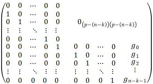
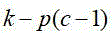
在本发明的一种具体实施方式中,第一编码模块31在进行RS编码时,当当前的并 行度

Figure 781770DEST_PATH_IMAGE001
小于
Figure 528009DEST_PATH_IMAGE013
时,初始系数矩阵
Figure 617188DEST_PATH_IMAGE004
采用
Figure 481808DEST_PATH_IMAGE014
,生成多项式系数矩阵
Figure 707253DEST_PATH_IMAGE005
采用
Figure 889972DEST_PATH_IMAGE015
; In a specific embodiment of the present invention, when the first encoding module 31 performs RS encoding, when the current parallelism
Figure 781770DEST_PATH_IMAGE001
less than
Figure 528009DEST_PATH_IMAGE013
, the initial coefficient matrix
Figure 617188DEST_PATH_IMAGE004
use
Figure 481808DEST_PATH_IMAGE014
, generating a polynomial coefficient matrix
Figure 707253DEST_PATH_IMAGE005
use
Figure 889972DEST_PATH_IMAGE015
;

当当前的并行度

Figure 200868DEST_PATH_IMAGE001
大于等于
Figure 861656DEST_PATH_IMAGE013
时,初始系数矩阵
Figure 692340DEST_PATH_IMAGE004
采用
Figure 45961DEST_PATH_IMAGE016
,生成多项式系数 矩阵
Figure 844153DEST_PATH_IMAGE005
采用
Figure 308632DEST_PATH_IMAGE017
; When the current degree of parallelism
Figure 200868DEST_PATH_IMAGE001
greater or equal to
Figure 861656DEST_PATH_IMAGE013
, the initial coefficient matrix
Figure 692340DEST_PATH_IMAGE004
use
Figure 45961DEST_PATH_IMAGE016
, generating a polynomial coefficient matrix
Figure 844153DEST_PATH_IMAGE005
use
Figure 308632DEST_PATH_IMAGE017
;

其中,

Figure 508670DEST_PATH_IMAGE011
表示的是一个码块共有
Figure 783924DEST_PATH_IMAGE011
个码元,
Figure 866150DEST_PATH_IMAGE012
表示的是
Figure 150632DEST_PATH_IMAGE011
个码元中有
Figure 205175DEST_PATH_IMAGE012
个信 息码元,
Figure 900599DEST_PATH_IMAGE018
Figure 407804DEST_PATH_IMAGE019
表示的是预设的生成多项式的
Figure 479665DEST_PATH_IMAGE013
个系数。 in,
Figure 508670DEST_PATH_IMAGE011
Indicates that a code block has a total of
Figure 783924DEST_PATH_IMAGE011
symbols,
Figure 866150DEST_PATH_IMAGE012
means that
Figure 150632DEST_PATH_IMAGE011
symbols in
Figure 205175DEST_PATH_IMAGE012
information symbols,
Figure 900599DEST_PATH_IMAGE018
to
Figure 407804DEST_PATH_IMAGE019
represents the preset generator polynomial
Figure 479665DEST_PATH_IMAGE013
a coefficient.

该种实施方式中考虑到,按照RS串行编码原理,每个周期只能按一个symbol size 编码,根据RS串行编码原理,可以用状态空间对并行编码进行描述。因此,当并行度

Figure 136518DEST_PATH_IMAGE001
小于
Figure 268422DEST_PATH_IMAGE013
时,初始系数矩阵
Figure 262923DEST_PATH_IMAGE004
可以采用
Figure 138475DEST_PATH_IMAGE014
,生成多项式系数矩阵
Figure 387185DEST_PATH_IMAGE005
采用
Figure 689990DEST_PATH_IMAGE015
。而当并行度
Figure 171787DEST_PATH_IMAGE001
大于等于
Figure 585451DEST_PATH_IMAGE013
时,初始系数矩阵
Figure 219825DEST_PATH_IMAGE004
和生成多项式系数矩 阵
Figure 427953DEST_PATH_IMAGE005
采用便按照上文描述进行调整,从而在并行度较大时有效地满足系统要求。 In this embodiment, it is considered that, according to the principle of RS serial coding, each cycle can only be coded according to one symbol size, and according to the principle of RS serial coding, the parallel coding can be described by a state space. Therefore, when the degree of parallelism
Figure 136518DEST_PATH_IMAGE001
less than
Figure 268422DEST_PATH_IMAGE013
, the initial coefficient matrix
Figure 262923DEST_PATH_IMAGE004
can be used
Figure 138475DEST_PATH_IMAGE014
, generating a polynomial coefficient matrix
Figure 387185DEST_PATH_IMAGE005
use
Figure 689990DEST_PATH_IMAGE015
. And when the degree of parallelism
Figure 171787DEST_PATH_IMAGE001
greater or equal to
Figure 585451DEST_PATH_IMAGE013
, the initial coefficient matrix
Figure 219825DEST_PATH_IMAGE004
and generator polynomial coefficient matrix
Figure 427953DEST_PATH_IMAGE005
The use is adjusted as described above to effectively meet the system requirements when the degree of parallelism is large.

进一步的,在本发明的一种具体实施方式中,第一编码模块31在进行RS编码时,具体用于:Further, in a specific embodiment of the present invention, when the first encoding module 31 performs RS encoding, it is specifically used for:

针对任意1个常系数的任意1次乘法计算,通过调用预先创建的常系数的乘法器,确定出针对常系数的本次乘法计算结果。For any one multiplication calculation of any one constant coefficient, by calling the pre-created multiplier of the constant coefficient, the result of this multiplication calculation for the constant coefficient is determined.

可以理解的是,对于第二编码模块32,也可以采用如该种实施方式中的第一编码模块31的实施方式,即通过调用预先创建的常系数的乘法器来得到乘法计算结果。It can be understood that, for the second encoding module 32, the implementation of the first encoding module 31 in this embodiment can also be used, that is, the multiplication result is obtained by invoking a pre-created multiplier with constant coefficients.

该种实施方式中对常系数乘法器进行优化。通常,计算出矩阵中的某个系数,即可以得出该系数的常系数乘法器,该乘法器在伽罗华域加法,即FPGA内实现为异或。以常系数523为例,通过在GF(210)域上从0到1023每一个数值与常系数523做乘法,即可得出该乘法器的查找表,该乘法器的部分查找表形式如表一 所示。In this embodiment, the constant coefficient multiplier is optimized. Usually, a certain coefficient in the matrix is calculated, that is, a constant coefficient multiplier for that coefficient can be obtained, which is implemented as an exclusive-OR in Galois field addition, that is, in an FPGA. Taking the constant coefficient 523 as an example, by multiplying each value from 0 to 1023 with the constant coefficient 523 on the GF(2 10 ) field, the look-up table of the multiplier can be obtained. The form of the partial look-up table of the multiplier is as follows shown in Table 1.

表一:常系数523的部分查找表Table 1: Partial look-up table for constant coefficient 523

Figure 397046DEST_PATH_IMAGE030

由表一可以看出,例如需要将常系数523与乘数0相乘时,结果为0,需要将常系数523与乘数1相乘时,结果为523,需要将常系数523与乘数2相乘时,结果为31。As can be seen from Table 1, for example, when the constant coefficient 523 needs to be multiplied by the multiplier 0, the result is 0, and when the constant coefficient 523 needs to be multiplied by the multiplier 1, the result is 523, and the constant coefficient 523 needs to be multiplied by the multiplier. When 2 is multiplied, the result is 31.

由于该种实施方式中,可以调用预先创建的常系数的乘法器,实现了乘法器优化,因此有利于进一步解决时序收敛难度高的问题,且单个乘法器减少逻辑资源消耗约0.1%,而编码中采用了大量的常系数乘法器,因此该种实施方式的设计可以有效地降低逻辑资源消耗。Because in this implementation, a pre-created multiplier with constant coefficients can be called to realize multiplier optimization, which is conducive to further solving the problem of high timing closure difficulty, and a single multiplier reduces logic resource consumption by about 0.1%, while coding A large number of constant-coefficient multipliers are used in this implementation, so the design of this embodiment can effectively reduce the consumption of logic resources.

此外,在预先创建各个常系数的乘法器时,可以通过MATLAB计算。In addition, when the multiplier of each constant coefficient is created in advance, it can be calculated by MATLAB.

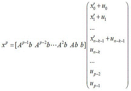
在本发明的一种具体实施方式中,考虑到通常是通过

Figure 614401DEST_PATH_IMAGE031
................公式(1) 进行校验码的生成,其中的
Figure 352549DEST_PATH_IMAGE032
。而根据编码系数矩阵的特点,可以得到是
Figure 747890DEST_PATH_IMAGE033
行为
Figure 204279DEST_PATH_IMAGE013
,列为
Figure 959745DEST_PATH_IMAGE013
的矩阵,该矩阵与矩阵
Figure 552401DEST_PATH_IMAGE034
相同,因此将公式(1)设计为:In one embodiment of the present invention, it is considered that generally by
Figure 614401DEST_PATH_IMAGE031
......Formula (1) to generate the check code, in which
Figure 352549DEST_PATH_IMAGE032
. According to the characteristics of the coding coefficient matrix, it can be obtained that
Figure 747890DEST_PATH_IMAGE033
Behavior
Figure 204279DEST_PATH_IMAGE013
, listed as
Figure 959745DEST_PATH_IMAGE013
, which is the same as the matrix
Figure 552401DEST_PATH_IMAGE034
the same, so formula (1) is designed as:

Figure 855993DEST_PATH_IMAGE002
........公式(2) 即在本发明的一种具体实施方式中,第一编码模块31在进行RS编码时,具体用于:通过公式 (2)进行校验码的生成。
Figure 855993DEST_PATH_IMAGE002
........Formula (2) That is, in a specific embodiment of the present invention, when the first coding module 31 performs RS coding, it is specifically used to: generate a check code by formula (2) .

其中,

Figure 799678DEST_PATH_IMAGE003
表示的是编码系数矩阵,
Figure 358835DEST_PATH_IMAGE004
表示的是初始系数矩阵,
Figure 805997DEST_PATH_IMAGE005
表示的是生 成多项式系数矩阵,
Figure 792408DEST_PATH_IMAGE006
Figure 442963DEST_PATH_IMAGE007
表示的是在当前计算周期计算之后的第0至第
Figure 540232DEST_PATH_IMAGE008
寄存器的值,
Figure 373059DEST_PATH_IMAGE009
Figure 530371DEST_PATH_IMAGE010
表示的是
Figure 917490DEST_PATH_IMAGE001
路输入数据,
Figure 569182DEST_PATH_IMAGE011
表示的是一个码块共 有
Figure 256515DEST_PATH_IMAGE011
个码元,
Figure 132199DEST_PATH_IMAGE012
表示的是
Figure 272193DEST_PATH_IMAGE011
个码元中有
Figure 445685DEST_PATH_IMAGE012
个信息码元。 in,
Figure 799678DEST_PATH_IMAGE003
represents the coding coefficient matrix,
Figure 358835DEST_PATH_IMAGE004
represents the initial coefficient matrix,
Figure 805997DEST_PATH_IMAGE005
represents the generator polynomial coefficient matrix,
Figure 792408DEST_PATH_IMAGE006
to
Figure 442963DEST_PATH_IMAGE007
Indicates the 0th to th
Figure 540232DEST_PATH_IMAGE008
the value of the register,
Figure 373059DEST_PATH_IMAGE009
to
Figure 530371DEST_PATH_IMAGE010
means that
Figure 917490DEST_PATH_IMAGE001
input data,
Figure 569182DEST_PATH_IMAGE011
Indicates that a code block has a total of
Figure 256515DEST_PATH_IMAGE011
symbols,
Figure 132199DEST_PATH_IMAGE012
means that
Figure 272193DEST_PATH_IMAGE011
symbols in
Figure 445685DEST_PATH_IMAGE012
information symbols.

可以看出,通过该种实施方式中的矩阵设计,进一步地降低了逻辑计算复杂度,即解决了编码反馈加法计算逻辑复杂问题,从而有利于在降低频率上的时序收敛要求It can be seen that through the matrix design in this embodiment, the complexity of logic calculation is further reduced, that is, the complex problem of code feedback addition calculation logic is solved, which is conducive to reducing the timing convergence requirement on frequency

因此,该种实施方式中,对于并行度

Figure 987525DEST_PATH_IMAGE001
的待编码数据,从第1至第
Figure 221060DEST_PATH_IMAGE013
组分别 与上一周期的计算反馈
Figure 861733DEST_PATH_IMAGE006
Figure 838916DEST_PATH_IMAGE035
...
Figure 235262DEST_PATH_IMAGE007
Figure 905278DEST_PATH_IMAGE036
相加,然后与矩阵相乘即可得出每个 周期的反馈冗余码,最后一个周期根据其并行度数值按照相同方法确定其矩阵即可,并将 最后的有效数据与矩阵计算得出冗余码
Figure 754285DEST_PATH_IMAGE013
个symbol size,按序放置在数据的最后一 个周期; Therefore, in this implementation, for the degree of parallelism
Figure 987525DEST_PATH_IMAGE001
the data to be encoded, from 1st to 1st
Figure 221060DEST_PATH_IMAGE013
Group separately and the calculated feedback of the previous cycle
Figure 861733DEST_PATH_IMAGE006
,
Figure 838916DEST_PATH_IMAGE035
...
Figure 235262DEST_PATH_IMAGE007
,
Figure 905278DEST_PATH_IMAGE036
Add, and then multiply with the matrix to get the feedback redundancy code of each cycle. The last cycle can determine its matrix according to its parallel degree value in the same way, and calculate the last valid data with the matrix to get the redundancy code. remainder
Figure 754285DEST_PATH_IMAGE013
symbol size, placed in order in the last cycle of the data;

此外需要说明的是,第一编码模块31和第二编码模块32在编码的同时,可以根据编码codeword的输入控制信号计数并控制编码的周期,该输入控制信号可以是脉冲信号。产生用于与编码后的codeword对应的输出控制信号,该输出控制信号也可以是脉冲信号。In addition, it should be noted that the first encoding module 31 and the second encoding module 32 can count and control the encoding period according to the input control signal of the encoding codeword while encoding, and the input control signal can be a pulse signal. An output control signal corresponding to the encoded codeword is generated, and the output control signal may also be a pulse signal.

输出合并模块40可以根据第三FIFO23和第四FIFO24的空和满的情况,产生读信 号,并且如上文的描述,读写第三FIFO23和第四FIFO24的时钟频率不一样,写是读的2分频, 因此对具体的一个第三FIFO23或者第四FIFO24的读信号,会在

Figure 551471DEST_PATH_IMAGE025
个周期内有效,
Figure 802324DEST_PATH_IMAGE025
个周 期内无效,如此交替。而因为有两路编码,因此输出合并模块40从第三FIFO23和第四FIFO24 读取的数据会交替,进而合并成一路数据输出,实现数据流的不间断输出。 The output merging module 40 can generate a read signal according to the empty and full conditions of the third FIFO 23 and the fourth FIFO 24, and as described above, the clock frequencies of reading and writing the third FIFO 23 and the fourth FIFO 24 are different, and writing is read 2 frequency division, so the read signal for a specific third FIFO23 or fourth FIFO24 will be
Figure 551471DEST_PATH_IMAGE025
valid for a period of time,
Figure 802324DEST_PATH_IMAGE025
Invalid within a period, and so on. Since there are two paths of encoding, the data read from the third FIFO 23 and the fourth FIFO 24 by the output combining module 40 will alternate, and then combined into one data output to realize uninterrupted output of the data stream.

本申请的方案中,进行的是并行度

Figure 643241DEST_PATH_IMAGE001
的编码,因此,
Figure 979544DEST_PATH_IMAGE001
的取值不能过低,但过高 也会增大编码复杂度,使得时序收敛难度提高。因此,在本发明的一种具体实施方式中,采 用并行度为64的编码,即
Figure 314842DEST_PATH_IMAGE001
为64,可以保证电路的最大时钟频率大于351.5625Mhz,二分频 时钟最大频率大于351.5625Mhz 2分频时钟,在数据接口宽度为1280比特的情况下,可以达 到425G/bits以上的数据吞吐率。 In the scheme of this application, the parallelism is carried out
Figure 643241DEST_PATH_IMAGE001
encoding, therefore,
Figure 979544DEST_PATH_IMAGE001
The value of can not be too low, but too high will increase the coding complexity, making the timing convergence more difficult. Therefore, in a specific implementation manner of the present invention, a code with a parallelism of 64 is used, that is,
Figure 314842DEST_PATH_IMAGE001
If it is 64, it can ensure that the maximum clock frequency of the circuit is greater than 351.5625Mhz, and the maximum frequency of the 2-frequency clock is greater than 351.5625Mhz 2-frequency clock. When the data interface width is 1280 bits, the data throughput rate of more than 425G/bits can be achieved.

进一步的,在本发明的一种具体实施方式中,RS编码装置可以采用

Figure 685780DEST_PATH_IMAGE011
=544,
Figure 697599DEST_PATH_IMAGE012
= 514,
Figure 786778DEST_PATH_IMAGE020
=15,
Figure 660187DEST_PATH_IMAGE021
=10的码组。其中,
Figure 620053DEST_PATH_IMAGE011
表示的是一个码块共有
Figure 68351DEST_PATH_IMAGE011
个码元,
Figure 379247DEST_PATH_IMAGE012
表示的是
Figure 305615DEST_PATH_IMAGE011
个码元中有
Figure 416526DEST_PATH_IMAGE012
个信息码元,
Figure 504568DEST_PATH_IMAGE020
表示的是能纠正的码元数目,
Figure 99497DEST_PATH_IMAGE021
表示的是单个码元包括
Figure 580288DEST_PATH_IMAGE021
位二进制数。 Further, in a specific implementation manner of the present invention, the RS encoding apparatus may adopt
Figure 685780DEST_PATH_IMAGE011
=544,
Figure 697599DEST_PATH_IMAGE012
= 514,
Figure 786778DEST_PATH_IMAGE020
=15,
Figure 660187DEST_PATH_IMAGE021
=10 code group. in,
Figure 620053DEST_PATH_IMAGE011
Indicates that a code block has a total of
Figure 68351DEST_PATH_IMAGE011
symbols,
Figure 379247DEST_PATH_IMAGE012
means that
Figure 305615DEST_PATH_IMAGE011
symbols in
Figure 416526DEST_PATH_IMAGE012
information symbols,
Figure 504568DEST_PATH_IMAGE020
represents the number of symbols that can be corrected,
Figure 99497DEST_PATH_IMAGE021
Indicates that a single symbol includes
Figure 580288DEST_PATH_IMAGE021
Bit binary number.

以RS(544,514,15,10)码组为例,IEEE802 .3协议进行说明,根据协议要求,实现该编码时序频率要求在351.5625MHz。根据协议要求,数据流有两路并行编码实现,因此可以得到给定的生成多项式,表示为:Taking the RS (544, 514, 15, 10) code group as an example, the IEEE802.3 protocol is used for description. According to the requirements of the protocol, the frequency requirement for realizing the coding sequence is 351.5625MHz. According to the requirements of the protocol, the data stream has two parallel encoding implementations, so the given generator polynomial can be obtained, which is expressed as:

Figure DEST_PATH_IMAGE037
。 该多项式的系数可以参阅表二 。
Figure DEST_PATH_IMAGE037
. The coefficients of this polynomial can be found in Table 2.

表二:多项式对应的系数表Table 2: The coefficient table corresponding to the polynomial

Figure 45905DEST_PATH_IMAGE038

单路编码codeword 为514个symbol,设定的每个周期计算位宽为640bit,即64个 symbol。并行度

Figure 570427DEST_PATH_IMAGE001
为64,
Figure 590336DEST_PATH_IMAGE026
不能整除,取整加1即为9,则最后一个周期的并行度 为514-(9-1)*64=2。The single-channel encoding codeword is 514 symbols, and the set calculation bit width of each cycle is 640 bits, that is, 64 symbols. degree of parallelism
Figure 570427DEST_PATH_IMAGE001
is 64,
Figure 590336DEST_PATH_IMAGE026
It is not divisible, and adding 1 to the integer is 9, then the parallelism of the last cycle is 514-(9-1)*64=2.

输入乒乓控制模块10可以根据codeword的脉冲信号in_pulse,将第一个codeword1在9个周期的数据及其输入控制信号写入第一FIFO21,相应的,第二个codeword2在9个周期的数据及其输入控制信号写入第二FIFO22,第三个codeword3在9个周期的数据及其输入控制信号写入第一FIFO21,如此交替。The input ping-pong control module 10 can write the data of the first codeword1 in 9 cycles and its input control signal into the first FIFO21 according to the pulse signal in_pulse of the codeword, correspondingly, the data of the second codeword2 in 9 cycles and its input control signal. The input control signal is written into the second FIFO22, the data of the third codeword3 and its input control signal in 9 cycles are written into the first FIFO21, and so on alternately.

第一编码电路通过9个周期将codeword读出编码,由于第一时钟域和第二时钟域的设置,读为写的2分频时钟频率,读完一个codeword1时,下个codeword3正好要写入,第一FIFO21不会为空,保证了数据的连续性和传输效率。第一编码电路在前8个周期按照并行度64编码,最后一个周期按并行度2编码,最终的编码结果写入第一编码电路中的第三FIFO23。第二编码电路同理。The first encoding circuit reads out the codeword through 9 cycles. Due to the settings of the first clock domain and the second clock domain, the reading is the clock frequency divided by 2 for writing. When one codeword1 is read, the next codeword3 is just about to be written. , the first FIFO 21 will not be empty, which ensures data continuity and transmission efficiency. The first encoding circuit encodes according to the degree of parallelism 64 in the first 8 cycles, and encodes according to the degree of parallelism 2 in the last cycle, and the final encoding result is written into the third FIFO23 in the first encoding circuit. The same is true for the second encoding circuit.

输出合并模块40可以产生读信号,因为第一时钟域和第二时钟域的设置,即写为读的2分频时钟频率,所以等待第三FIFO23不空9个周期才开始读数据,从第三FIFO23读取9个周期数据后,第三FIFO23中的codeword1被完全读取,然后用9个周期从第四FIFO24中读取codeword2,再用9个周期从第三FIFO23中读取codeword3,依次交替,实现编码后数据的整合,保证了数据流的连续性。The output merging module 40 can generate the read signal. Because of the setting of the first clock domain and the second clock domain, that is, the writing is the clock frequency divided by 2 for reading, so wait until the third FIFO 23 is not empty for 9 cycles before starting to read data. After the third FIFO23 reads 9 cycles of data, the codeword1 in the third FIFO23 is completely read, then it takes 9 cycles to read codeword2 from the fourth FIFO24, and then it takes 9 cycles to read codeword3 from the third FIFO23, and in turn Alternately, the integration of the encoded data is realized, and the continuity of the data flow is ensured.

应用本发明实施例所提供的技术方案,输入乒乓控制模块10可以接收待编码数 据,并按照乒乓方式交替分配至第一FIFO21和第二FIFO22,且分配时进行并行输出,第一编 码模块31和第二编码模块32,则可以分别读取第一FIFO21和第二FIFO22中存储的数据,并 对

Figure 609238DEST_PATH_IMAGE001
路并行数据进行RS编码,将编码结果及相应的输出控制信号相应地写入第三FIFO23 和第四FIFO24。可以看出,由于第一编码模块31和第二编码模块32均是同时处理
Figure 398203DEST_PATH_IMAGE001
路并行 数据,因此可以有效地实现高系统传输效率。并且,本申请的方案中,第一FIFO21的写周期、 第二FIFO22的写周期、第三FIFO23的读周期以及第四FIFO24的读周期均采用周期为T的第 一时钟域,第一FIFO21的读周期,第二FIFO22的读周期,第三FIFO23的写周期,第四FIFO24 的写周期,第一编码模块31的时钟,以及第二编码模块32的时钟均采用周期为2T的第二时 钟域。因此,对于第一编码模块31和第二编码模块32而言,相当于是降低了读频率,实现了 降频编码,这样使得系统传输效率较高时,本申请的方案也能够实现时序收敛,满足编码效 率的要求。综上所述,本申请的方案可以有效地实现高系统传输效率的RS编码。 Applying the technical solution provided by the embodiment of the present invention, the input ping-pong control module 10 can receive the data to be encoded, and alternately distribute it to the first FIFO 21 and the second FIFO 22 in a ping-pong manner, and perform parallel output during distribution. The first encoding module 31 and The second encoding module 32 can read the data stored in the first FIFO 21 and the second FIFO 22, respectively, and
Figure 609238DEST_PATH_IMAGE001
RS encoding is performed on the parallel data of the channels, and the encoding result and the corresponding output control signal are written into the third FIFO23 and the fourth FIFO24 accordingly. It can be seen that since the first encoding module 31 and the second encoding module 32 both process at the same time
Figure 398203DEST_PATH_IMAGE001
parallel data, so it can effectively achieve high system transmission efficiency. Moreover, in the solution of the present application, the write cycle of the first FIFO21, the write cycle of the second FIFO22, the read cycle of the third FIFO23 and the read cycle of the fourth FIFO24 all use the first clock domain with a cycle of T, and the first clock domain of the first FIFO21 The read cycle, the read cycle of the second FIFO22, the write cycle of the third FIFO23, the write cycle of the fourth FIFO24, the clock of the first encoding module 31, and the clock of the second encoding module 32 all use the second clock domain with a cycle of 2T. . Therefore, for the first encoding module 31 and the second encoding module 32, it is equivalent to reducing the reading frequency and realizing the down-frequency encoding, so that when the system transmission efficiency is high, the solution of the present application can also achieve timing convergence, satisfying coding efficiency requirements. To sum up, the solution of the present application can effectively realize RS coding with high system transmission efficiency.

相应于上面的方法实施例,本发明实施例还提供了一种数据传输系统以及一种RS编码方法,可与上文相互对应参照。该数据传输系统可以包括如上述任一实施例中的RS编码装置。Corresponding to the above method embodiments, the embodiments of the present invention further provide a data transmission system and an RS coding method, which can be referred to in correspondence with the above. The data transmission system may include the RS encoding apparatus as in any of the above embodiments.

该RS编码方法可以包括以下步骤:The RS encoding method may include the following steps:

步骤一:输入乒乓控制模块接收待编码数据,并按照乒乓方式交替分配至第一FIFO和第二FIFO,且分配时进行并行输出;Step 1: input the ping-pong control module to receive the data to be encoded, and alternately allocate it to the first FIFO and the second FIFO according to the ping-pong method, and perform parallel output during allocation;

步骤二:第一FIFO接收输入乒乓控制模块输出的待编码数据以及相应的输入控制信号;Step 2: the first FIFO receives the data to be encoded and the corresponding input control signal output by the input ping-pong control module;

步骤三:第二FIFO接收输入乒乓控制模块输出的待编码数据以及相应的输入控制信号;Step 3: the second FIFO receives the data to be encoded and the corresponding input control signal output by the input ping-pong control module;

步骤四:第一编码模块读取第一FIFO中存储的数据,并对

Figure 359206DEST_PATH_IMAGE001
路并行数据进行RS编 码,将编码结果及相应的输出控制信号写入第三FIFO; Step 4: The first encoding module reads the data stored in the first FIFO, and
Figure 359206DEST_PATH_IMAGE001
RS encoding is performed on the parallel data of the channel, and the encoding result and the corresponding output control signal are written into the third FIFO;

步骤五:第二编码模块读取第二FIFO中存储的数据,并对

Figure 131990DEST_PATH_IMAGE001
路并行数据进行RS编 码,将编码结果及相应的输出控制信号写入第四FIFO; Step 5: The second encoding module reads the data stored in the second FIFO, and
Figure 131990DEST_PATH_IMAGE001
RS encoding is performed on the parallel data of the channel, and the encoding result and the corresponding output control signal are written into the fourth FIFO;

步骤六:输出合并模块从第三FIFO和第四FIFO中交替读取数据,以进行编码后的数据整合;Step 6: the output merging module alternately reads data from the third FIFO and the fourth FIFO to integrate the encoded data;

其中,

Figure 672692DEST_PATH_IMAGE001
为不小于2的正整数;第一FIFO的写周期、第二FIFO的写周期、第三FIFO 的读周期以及第四FIFO的读周期均采用周期为T的第一时钟域;第一FIFO的读周期,第二 FIFO的读周期,第三FIFO的写周期,第四FIFO的写周期,第一编码模块的时钟,以及第二编 码模块的时钟均采用周期为2T的第二时钟域。 in,
Figure 672692DEST_PATH_IMAGE001
is a positive integer not less than 2; the write cycle of the first FIFO, the write cycle of the second FIFO, the read cycle of the third FIFO, and the read cycle of the fourth FIFO all use the first clock domain with a cycle of T; The read cycle, the read cycle of the second FIFO, the write cycle of the third FIFO, the write cycle of the fourth FIFO, the clock of the first encoding module, and the clock of the second encoding module all use the second clock domain with a period of 2T.

在本发明的一种具体实施方式中,第一编码模块在进行RS编码时,通过

Figure 598054DEST_PATH_IMAGE002
进行校验码的生成; In a specific embodiment of the present invention, when the first encoding module performs RS encoding, the
Figure 598054DEST_PATH_IMAGE002
Generate a check code;

其中,

Figure 729958DEST_PATH_IMAGE003
表示的是编码系数矩阵,
Figure 724459DEST_PATH_IMAGE004
表示的是初始系数矩阵,
Figure 334432DEST_PATH_IMAGE005
表示的是生 成多项式系数矩阵,
Figure 111371DEST_PATH_IMAGE006
Figure 414176DEST_PATH_IMAGE007
表示的是在当前计算周期计算之后的第0至第
Figure 630394DEST_PATH_IMAGE008
寄存器的值,
Figure 44057DEST_PATH_IMAGE009
Figure 662121DEST_PATH_IMAGE010
表示的是
Figure 886560DEST_PATH_IMAGE001
路输入数据,
Figure 855653DEST_PATH_IMAGE011
表示的是一个码块共 有
Figure 541849DEST_PATH_IMAGE011
个码元,
Figure 545577DEST_PATH_IMAGE012
表示的是
Figure 940917DEST_PATH_IMAGE011
个码元中有
Figure 131727DEST_PATH_IMAGE012
个信息码元。 in,
Figure 729958DEST_PATH_IMAGE003
represents the coding coefficient matrix,
Figure 724459DEST_PATH_IMAGE004
represents the initial coefficient matrix,
Figure 334432DEST_PATH_IMAGE005
represents the generator polynomial coefficient matrix,
Figure 111371DEST_PATH_IMAGE006
to
Figure 414176DEST_PATH_IMAGE007
Indicates the 0th to th
Figure 630394DEST_PATH_IMAGE008
the value of the register,
Figure 44057DEST_PATH_IMAGE009
to
Figure 662121DEST_PATH_IMAGE010
means that
Figure 886560DEST_PATH_IMAGE001
input data,
Figure 855653DEST_PATH_IMAGE011
Indicates that a code block has a total of
Figure 541849DEST_PATH_IMAGE011
symbols,
Figure 545577DEST_PATH_IMAGE012
means that
Figure 940917DEST_PATH_IMAGE011
symbols in
Figure 131727DEST_PATH_IMAGE012
information symbols.

在本发明的一种具体实施方式中,第一编码模块在进行RS编码时,针对任意1个常系数的任意1次乘法计算,通过调用预先创建的常系数的乘法器,确定出针对常系数的本次乘法计算结果。In a specific embodiment of the present invention, when the first encoding module performs RS encoding, for any one multiplication calculation of any one constant coefficient, by calling a pre-created multiplier of constant coefficients, the first encoding module determines the constant coefficient for the constant coefficient. The result of this multiplication calculation.

还需要说明的是,在本文中,诸如第一和第二等之类的关系术语仅仅用来将一个实体或者操作与另一个实体或操作区分开来,而不一定要求或者暗示这些实体或操作之间存在任何这种实际的关系或者顺序。而且,术语“包括”、“包含”或者其任何其他变体意在涵盖非排他性的包含,从而使得包括一系列要素的过程、方法、物品或者设备不仅包括那些要素,而且还包括没有明确列出的其他要素,或者是还包括为这种过程、方法、物品或者设备所固有的要素。在没有更多限制的情况下,由语句“包括一个……”限定的要素,并不排除在包括所述要素的过程、方法、物品或者设备中还存在另外的相同要素。It should also be noted that in this document, relational terms such as first and second are used only to distinguish one entity or operation from another, and do not necessarily require or imply those entities or operations There is no such actual relationship or order between them. Moreover, the terms "comprising", "comprising" or any other variation thereof are intended to encompass a non-exclusive inclusion such that a process, method, article or device that includes a list of elements includes not only those elements, but also includes not explicitly listed or other elements inherent to such a process, method, article or apparatus. Without further limitation, an element qualified by the phrase "comprising a..." does not preclude the presence of additional identical elements in a process, method, article or apparatus that includes the element.

结合本文中所公开的实施例描述的方法或算法的步骤可以直接用硬件、处理器执行的软件模块,或者二者的结合来实施。软件模块可以置于随机存储器(RAM)、内存、只读存储器(ROM)、电可编程ROM、电可擦除可编程ROM、寄存器、硬盘、可移动磁盘、CD-ROM、或技术领域内所公知的任意其它形式的存储介质中。专业人员还可以进一步意识到,结合本文中所公开的实施例描述的各示例的单元及算法步骤,能够以电子硬件、计算机软件或者二者的结合来实现,为了清楚地说明硬件和软件的可互换性,在上述说明中已经按照功能一般性地描述了各示例的组成及步骤。这些功能究竟以硬件还是软件方式来执行,取决于技术方案的特定应用和设计约束条件。专业技术人员可以对每个特定的应用来使用不同方法来实现所描述的功能,但是这种实现不应认为超出本发明的范围。The steps of a method or algorithm described in conjunction with the embodiments disclosed herein may be directly implemented in hardware, a software module executed by a processor, or a combination of the two. Software modules can be placed in random access memory (RAM), internal memory, read only memory (ROM), electrically programmable ROM, electrically erasable programmable ROM, registers, hard disk, removable disk, CD-ROM, or any other in the technical field. in any other known form of storage medium. Professionals may further realize that the units and algorithm steps of each example described in conjunction with the embodiments disclosed herein can be implemented in electronic hardware, computer software, or a combination of the two, in order to clearly illustrate the possibilities of hardware and software. Interchangeability, the above description has generally described the components and steps of each example in terms of functionality. Whether these functions are performed in hardware or software depends on the specific application and design constraints of the technical solution. Skilled artisans may implement the described functionality using different methods for each particular application, but such implementations should not be considered beyond the scope of the present invention.

本文中应用了具体个例对本发明的原理及实施方式进行了阐述,以上实施例的说明只是用于帮助理解本发明的技术方案及其核心思想。应当指出,对于本技术领域的普通技术人员来说,在不脱离本发明原理的前提下,还可以对本发明进行若干改进和修饰,这些改进和修饰也落入本发明权利要求的保护范围内。The principles and implementations of the present invention are described herein by using specific examples, and the descriptions of the above embodiments are only used to help understand the technical solutions and core ideas of the present invention. It should be pointed out that for those skilled in the art, without departing from the principle of the present invention, several improvements and modifications can also be made to the present invention, and these improvements and modifications also fall within the protection scope of the claims of the present invention.

Claims (7)

1. An RS encoding apparatus, comprising:
the input ping-pong control module is used for receiving data to be coded, alternately distributing the data to the first FIFO and the second FIFO according to a ping-pong mode, and outputting the data in parallel during distribution;
the first FIFO is used for receiving the data to be encoded output by the input ping-pong control module and a corresponding input control signal;
the second FIFO is used for receiving the data to be encoded output by the input ping-pong control module and a corresponding input control signal;
a first encoding module for reading the data stored in the first FIFO and encoding the data
Figure DEST_PATH_IMAGE002
RS encoding is carried out on the channel parallel data, and an encoding result and a corresponding output control signal are written into a third FIFO;
a second encoding module for reading the data stored in the second FIFO and encoding the data
Figure DEST_PATH_IMAGE002A
RS encoding is carried out on the channel parallel data, and an encoding result and a corresponding output control signal are written into a fourth FIFO;
the output merging module is used for alternately reading data from the third FIFO and the fourth FIFO so as to perform coded data integration;
wherein,
Figure DEST_PATH_IMAGE002AA
for the purpose of parallelism in the parallel encoding,
Figure DEST_PATH_IMAGE002AAA
is a positive integer not less than 2; the writing period of the first FIFO, the writing period of the second FIFO, the reading period of the third FIFO and the reading period of the fourth FIFO all adopt a first clock domain with the period of T; a read period of the first FIFO, a read period of the second FIFO, a write period of the third FIFO, a write period of the fourth FIFO, a clock of the first encoding module and a clock of the second encoding module all adopt a second clock domain with a period of 2T;
when the first encoding module performs RS encoding, the first encoding module is specifically configured to:
by passing
Figure DEST_PATH_IMAGE004
Generating a check code;
wherein,
Figure DEST_PATH_IMAGE006
it is indicated that the matrix of coding coefficients,
Figure DEST_PATH_IMAGE008
it is represented that the initial coefficient matrix,
Figure DEST_PATH_IMAGE010
the polynomial coefficient matrix is generated to represent,
Figure DEST_PATH_IMAGE012
to
Figure DEST_PATH_IMAGE014
Expressed are the 0 th to the 0 th after the calculation of the current calculation cycle
Figure DEST_PATH_IMAGE016
The value of the register is set to a value,
Figure DEST_PATH_IMAGE018
to
Figure DEST_PATH_IMAGE020
Is shown as
Figure DEST_PATH_IMAGE002AAAA
The way inputs the data and the way inputs the data,
Figure DEST_PATH_IMAGE022
indicating that one code block is common
Figure DEST_PATH_IMAGE022A
One of the symbols is a symbol that is,
Figure DEST_PATH_IMAGE024
is shown as
Figure DEST_PATH_IMAGE022AA
One code element has
Figure DEST_PATH_IMAGE024A
An information symbol;
when the first coding module carries out RS coding, the current parallelism degree
Figure DEST_PATH_IMAGE002_5A
Is less than
Figure DEST_PATH_IMAGE026
Time, initial coefficient matrix
Figure DEST_PATH_IMAGE008A
By using
Figure DEST_PATH_IMAGE028
Generating a polynomial coefficient matrix
Figure DEST_PATH_IMAGE010A
By using
Figure DEST_PATH_IMAGE030
When the current parallelism
Figure DEST_PATH_IMAGE002_6A
Is greater than or equal to
Figure DEST_PATH_IMAGE026A
Time, initial coefficient matrix
Figure DEST_PATH_IMAGE008AA
By using
Figure DEST_PATH_IMAGE032
Generating a polynomial coefficient matrix
Figure DEST_PATH_IMAGE010AA
By using
Figure DEST_PATH_IMAGE034
Wherein,
Figure DEST_PATH_IMAGE022AAA
indicating that one code block is common
Figure DEST_PATH_IMAGE022AAAA
One of the symbols is a symbol that is,
Figure DEST_PATH_IMAGE024AA
is shown as
Figure DEST_PATH_IMAGE022_5A
One code element has
Figure DEST_PATH_IMAGE024AAA
One of the information symbols is transmitted to the receiver,
Figure DEST_PATH_IMAGE036
to
Figure DEST_PATH_IMAGE038
Representing preset generator polynomials
Figure DEST_PATH_IMAGE026AA
A coefficient.
2. The RS encoding device of claim 1, wherein the first encoding module, when performing RS encoding, is specifically configured to:
and aiming at any 1-time multiplication calculation of any 1 constant coefficient, determining the multiplication calculation result of the constant coefficient at this time by calling the pre-created multiplier of the constant coefficient.
3. The RS encoding device of claim 1,
Figure DEST_PATH_IMAGE002_7A
is 64.
4. The RS encoding device of claim 3, wherein the RS encoding device employs
Figure DEST_PATH_IMAGE022_6A
=544,
Figure DEST_PATH_IMAGE024AAAA
=514,
Figure DEST_PATH_IMAGE040
=15,
Figure DEST_PATH_IMAGE042
Code group of = 10;
wherein,
Figure DEST_PATH_IMAGE022_7A
indicating that one code block is common
Figure DEST_PATH_IMAGE022_8A
One of the symbols is a symbol that is,
Figure DEST_PATH_IMAGE024_5A
is shown as
Figure DEST_PATH_IMAGE022_9A
One code element has
Figure DEST_PATH_IMAGE024_6A
One of the information symbols is transmitted to the receiver,
Figure DEST_PATH_IMAGE040A
indicating the number of symbols that can be corrected,
Figure DEST_PATH_IMAGE042A
representing a single symbol comprising
Figure DEST_PATH_IMAGE042AA
A binary number of bits.
5. A data transmission system comprising the RS encoding apparatus according to any one of claims 1 to 4.
6. An RS encoding method, comprising:
the input ping-pong control module receives data to be coded, alternately distributes the data to the first FIFO and the second FIFO according to a ping-pong mode, and performs parallel output during distribution;
the first FIFO receives the data to be encoded output by the input ping-pong control module and a corresponding input control signal;
the second FIFO receives the data to be encoded output by the input ping-pong control module and a corresponding input control signal;
the first coding module reads the data stored in the first FIFO and compares the data with the data stored in the first FIFO
Figure DEST_PATH_IMAGE002_8A
RS encoding is carried out on the channel parallel data, and an encoding result and a corresponding output control signal are written into a third FIFO;
the second coding module reads the data stored in the second FIFO and performs data conversion on the data
Figure DEST_PATH_IMAGE002_9A
RS encoding is carried out on the channel parallel data, and an encoding result and a corresponding output control signal are written into a fourth FIFO;
the output merging module alternately reads data from the third FIFO and the fourth FIFO so as to carry out encoded data integration;
wherein,
Figure DEST_PATH_IMAGE002_10A
for the purpose of parallelism in the parallel encoding,
Figure DEST_PATH_IMAGE002_11A
is a positive integer not less than 2; the writing period of the first FIFO, the writing period of the second FIFO, the reading period of the third FIFO and the reading period of the fourth FIFO all adopt a first clock domain with the period of T; a read period of the first FIFO, a read period of the second FIFO, a write period of the third FIFO, a write period of the fourth FIFO, a clock of the first encoding module and a clock of the second encoding module all adopt a second clock domain with a period of 2T;
the first coding module passes through when RS coding is carried out
Figure DEST_PATH_IMAGE043
Generating a check code;
wherein,
Figure DEST_PATH_IMAGE006A
it is indicated that the matrix of coding coefficients,
Figure DEST_PATH_IMAGE008AAA
it is represented that the initial coefficient matrix,
Figure DEST_PATH_IMAGE010AAA
the expression is to generate a polynomial coefficient matrix,
Figure DEST_PATH_IMAGE012A
to
Figure DEST_PATH_IMAGE014A
Expressed are the 0 th to the 0 th after the calculation of the current calculation cycle
Figure DEST_PATH_IMAGE016A
The value of the register is set to a value,
Figure DEST_PATH_IMAGE018A
to
Figure DEST_PATH_IMAGE020A
Is shown as
Figure DEST_PATH_IMAGE002_12A
The way inputs the data and the way inputs the data,
Figure DEST_PATH_IMAGE022_10A
indicating that one code block is common
Figure DEST_PATH_IMAGE022_11A
One of the symbols is a symbol that is,
Figure DEST_PATH_IMAGE024_7A
is shown as
Figure DEST_PATH_IMAGE022_12A
One code element has
Figure DEST_PATH_IMAGE024_8A
Personal informationAn information element;
when the first coding module carries out RS coding, the current parallelism degree
Figure DEST_PATH_IMAGE002_13A
Is less than
Figure DEST_PATH_IMAGE026AAA
Time, initial coefficient matrix
Figure DEST_PATH_IMAGE008AAAA
By using
Figure DEST_PATH_IMAGE028A
Generating a polynomial coefficient matrix
Figure DEST_PATH_IMAGE010AAAA
By using
Figure DEST_PATH_IMAGE030A
When the current parallelism
Figure DEST_PATH_IMAGE002_14A
Is greater than or equal to
Figure DEST_PATH_IMAGE026AAAA
Time, initial coefficient matrix
Figure DEST_PATH_IMAGE008_5A
By using
Figure DEST_PATH_IMAGE032A
Generating a polynomial coefficient matrix
Figure DEST_PATH_IMAGE010_5A
By using
Figure DEST_PATH_IMAGE034A
Wherein,
Figure DEST_PATH_IMAGE022_13A
indicating that one code block is common
Figure DEST_PATH_IMAGE022_14A
One of the symbols is a symbol that is,
Figure DEST_PATH_IMAGE024_9A
is shown as
Figure DEST_PATH_IMAGE022_15A
One code element has
Figure DEST_PATH_IMAGE024_10A
One of the information symbols is transmitted to the receiver,
Figure DEST_PATH_IMAGE036A
to
Figure DEST_PATH_IMAGE038A
Representing preset generator polynomials
Figure DEST_PATH_IMAGE026_5A
A coefficient.
7. The RS encoding method of claim 6, wherein the first encoding module determines the result of the multiplication for any 1 constant coefficient by calling a pre-created multiplier of the constant coefficient for any 1 multiplication for any 1 constant coefficient during RS encoding.
CN202210389397.2A 2022-04-14 2022-04-14 Data transmission system and RS encoding device and method thereof Active CN114499767B (en)

Priority Applications (1)

Application Number Priority Date Filing Date Title
CN202210389397.2A CN114499767B (en) 2022-04-14 2022-04-14 Data transmission system and RS encoding device and method thereof

Applications Claiming Priority (1)

Application Number Priority Date Filing Date Title
CN202210389397.2A CN114499767B (en) 2022-04-14 2022-04-14 Data transmission system and RS encoding device and method thereof

Publications (2)

Publication Number Publication Date
CN114499767A CN114499767A (en) 2022-05-13
CN114499767B true CN114499767B (en) 2022-08-05

Family

ID=81487587

Family Applications (1)

Application Number Title Priority Date Filing Date
CN202210389397.2A Active CN114499767B (en) 2022-04-14 2022-04-14 Data transmission system and RS encoding device and method thereof

Country Status (1)

Country Link
CN (1) CN114499767B (en)

Families Citing this family (3)

* Cited by examiner, † Cited by third party
Publication number Priority date Publication date Assignee Title
CN116722954B (en) * 2023-08-08 2023-10-20 珠海星云智联科技有限公司 Encoding and decoding verification system, method, equipment and storage medium
CN117254823B (en) * 2023-11-20 2024-03-15 苏州联讯仪器股份有限公司 Parallel RS encoding method, device and system and computer storage medium
CN117789805B (en) * 2024-02-26 2024-07-02 上海励驰半导体有限公司 Signal monitoring method and device, chip and electronic equipment

Citations (5)

* Cited by examiner, † Cited by third party
Publication number Priority date Publication date Assignee Title
EP0911984A1 (en) * 1997-10-21 1999-04-28 Deutsche Thomson-Brandt Gmbh Reed solomon error correction with shared memory approach
CN102122964A (en) * 2011-03-31 2011-07-13 西安电子科技大学 Implementation method of high-speed reed-solomon (RS) codec based on field programmable gate array (FPGA)
EP2418797A2 (en) * 2010-08-13 2012-02-15 ZTE (USA), Inc. Method for multiplexing uplink control information on a physical uplink shared channel
CN111294059A (en) * 2019-12-26 2020-06-16 成都海光集成电路设计有限公司 Encoding method, decoding method, error correction method and related device
CN112468161A (en) * 2020-12-01 2021-03-09 西安邮电大学 RS high-speed coding circuit

Family Cites Families (1)

* Cited by examiner, † Cited by third party
Publication number Priority date Publication date Assignee Title
CN101969358B (en) * 2010-09-29 2012-12-26 航天恒星科技有限公司 High-speed parallel RS decoding method for space communication

Patent Citations (5)

* Cited by examiner, † Cited by third party
Publication number Priority date Publication date Assignee Title
EP0911984A1 (en) * 1997-10-21 1999-04-28 Deutsche Thomson-Brandt Gmbh Reed solomon error correction with shared memory approach
EP2418797A2 (en) * 2010-08-13 2012-02-15 ZTE (USA), Inc. Method for multiplexing uplink control information on a physical uplink shared channel
CN102122964A (en) * 2011-03-31 2011-07-13 西安电子科技大学 Implementation method of high-speed reed-solomon (RS) codec based on field programmable gate array (FPGA)
CN111294059A (en) * 2019-12-26 2020-06-16 成都海光集成电路设计有限公司 Encoding method, decoding method, error correction method and related device
CN112468161A (en) * 2020-12-01 2021-03-09 西安邮电大学 RS high-speed coding circuit

Non-Patent Citations (1)

* Cited by examiner, † Cited by third party
Title
"一种100G EPON系统RS编码器设计与实现";杜慧敏等;《西安邮电大学学报》;20210110;第1-4部分 *

Also Published As

Publication number Publication date
CN114499767A (en) 2022-05-13

Similar Documents

Publication Publication Date Title
CN114499767B (en) Data transmission system and RS encoding device and method thereof
US9450615B2 (en) Multi-bit error correction method and apparatus based on a BCH code and memory system
US6920600B2 (en) Dual chien search blocks in an error-correcting decoder
MXPA04007076A (en) Intra-decoder component block messaging.
CN110741562B (en) Pipelined forward error correction for vector signaling code channels
US12401449B2 (en) Data transmission method, apparatus, device, system, and readable storage medium
CN110380738B (en) Parameter Software Configurable RS Encoder IP Core Circuit Structure and Encoding Method
US11184034B2 (en) Method and device for decoding staircase code, and storage medium
CN1636324A (en) Chien search cell for an error-correcting decoder
WO2012174933A1 (en) Rs encoder and encoding method thereof
US7360142B1 (en) Methods, architectures, circuits, software and systems for CRC determination
US11341047B2 (en) Data processing apparatus, and data processing method
CN100546206C (en) A circuit and method for realizing decoding
US7320101B1 (en) Fast parallel calculation of cyclic redundancy checks
WO2012109872A1 (en) Method, apparatus and lte terminals for cyclic redundancy checking in communication system
CN114303320B (en) Cyclic Redundancy Check (CRC) using inverse CRC generator polynomials for decoding
CN119766254A (en) Data processing method, data processing device and data transmission system
CN118611685A (en) A nonlinear code encoding method and system with lower redundancy
CN115632662A (en) Syndrome calculation method, device, equipment and medium in RS decoding
US12549280B2 (en) Electronic device and operation method therefor
WO2025066722A1 (en) Data processing method and related apparatus
Juan et al. Utilization of DSP algorithms for Cyclic Redundancy Checking (CRC) in Controller Area Network (CAN) controller
CN101030834B (en) Method and device for reducing error floor of low-density parity-check coding
CN121283571A (en) Data grouping method and device, electronic equipment, storage medium and computer program product
CN120880460A (en) Data encoding and decoding method, device and system

Legal Events

Date Code Title Description
PB01 Publication
PB01 Publication
SE01 Entry into force of request for substantive examination
GR01 Patent grant
GR01 Patent grant
CP03 Change of name, title or address

Address after: Building 5, No. 1508, Xiangjiang Road, Suzhou High-tech Zone, Suzhou City, Jiangsu Province 215129

Patentee after: Suzhou Lianxun Instrument Co.,Ltd.

Address before: 215129 Building 1, No. 1508, Xiangjiang Road, high tech Zone, Suzhou, Jiangsu

Patentee before: STELIGHT INSTRUMENT Inc.

CP03 Change of name, title or address