CN114481848A - Equipment for installing high pier template and using method thereof - Google Patents
Equipment for installing high pier template and using method thereof Download PDFInfo
- Publication number
- CN114481848A CN114481848A CN202210139398.1A CN202210139398A CN114481848A CN 114481848 A CN114481848 A CN 114481848A CN 202210139398 A CN202210139398 A CN 202210139398A CN 114481848 A CN114481848 A CN 114481848A
- Authority
- CN
- China
- Prior art keywords
- template
- plate
- fixedly connected
- equipment
- templates
- Prior art date
- Legal status (The legal status is an assumption and is not a legal conclusion. Google has not performed a legal analysis and makes no representation as to the accuracy of the status listed.)
- Granted
Links
- 238000000034 method Methods 0.000 title claims abstract description 21
- 230000002787 reinforcement Effects 0.000 claims abstract description 21
- 238000009434 installation Methods 0.000 claims description 38
- 238000009415 formwork Methods 0.000 claims description 34
- 229910000831 Steel Inorganic materials 0.000 claims description 11
- 239000010959 steel Substances 0.000 claims description 11
- 238000010276 construction Methods 0.000 abstract description 2
- 238000010586 diagram Methods 0.000 description 2
- 230000009286 beneficial effect Effects 0.000 description 1
- 239000004568 cement Substances 0.000 description 1
- 230000003014 reinforcing effect Effects 0.000 description 1
Images


Classifications
-
- E—FIXED CONSTRUCTIONS
- E01—CONSTRUCTION OF ROADS, RAILWAYS, OR BRIDGES
- E01D—CONSTRUCTION OF BRIDGES, ELEVATED ROADWAYS OR VIADUCTS; ASSEMBLY OF BRIDGES
- E01D21/00—Methods or apparatus specially adapted for erecting or assembling bridges
-
- E—FIXED CONSTRUCTIONS
- E01—CONSTRUCTION OF ROADS, RAILWAYS, OR BRIDGES
- E01D—CONSTRUCTION OF BRIDGES, ELEVATED ROADWAYS OR VIADUCTS; ASSEMBLY OF BRIDGES
- E01D19/00—Structural or constructional details of bridges
- E01D19/02—Piers; Abutments ; Protecting same against drifting ice
-
- E—FIXED CONSTRUCTIONS
- E01—CONSTRUCTION OF ROADS, RAILWAYS, OR BRIDGES
- E01D—CONSTRUCTION OF BRIDGES, ELEVATED ROADWAYS OR VIADUCTS; ASSEMBLY OF BRIDGES
- E01D2101/00—Material constitution of bridges
- E01D2101/20—Concrete, stone or stone-like material
- E01D2101/24—Concrete
- E01D2101/26—Concrete reinforced
Landscapes
- Engineering & Computer Science (AREA)
- Architecture (AREA)
- Civil Engineering (AREA)
- Structural Engineering (AREA)
- Bridges Or Land Bridges (AREA)
Abstract
Description
技术领域technical field
本发明涉及桥墩施工设备技术领域,尤其涉及一种用于高桥墩模板安装的设备及其使用方法。The invention relates to the technical field of bridge pier construction equipment, in particular to a device for installing a formwork for a high bridge pier and a method of using the same.
背景技术Background technique
桥墩是支承桥跨结构并将恒载和车辆活载传至地基的亚筑物、桥台设在桥梁两侧,桥墩则在两桥台之间,桥墩的作用是支承桥跨结构: 而桥台支撑起支承桥跨结构的作用外,还要与路堤衔接并防止路堤滑场,为保护桥台和路堤填土,桥台两侧常做一些防护和导流工程。The bridge pier is a sub-structure that supports the bridge span structure and transmits the dead load and vehicle live load to the foundation. The bridge abutment is located on both sides of the bridge, and the bridge pier is between the two bridge abutments. The function of the bridge pier is to support the bridge span structure: The bridge In addition to supporting the bridge span structure, the abutment support should also be connected with the embankment and prevent the embankment from slipping.
高桥墩在安装时,需要先固定钢筋笼,再将模板设置在钢筋笼的周围并固定,最后浇筑水泥,现有的模板在安装时,需要依靠人工将模板运送至指定高度,再将其放置在合适的位置,完成安装,操作过程繁琐,并且需要借助大型起吊器械,也无法保证工人的人身安全,较为危险,所以我们提出一种用于高桥墩模板安装的设备及其使用方法,用以解决上述所提到的问题。When the high bridge pier is installed, it is necessary to fix the steel cage first, then set the formwork around the steel cage and fix it, and finally pour the cement. When the existing formwork is installed, it needs to rely on manual transportation of the formwork to the specified height, and then place it. It is very dangerous to complete the installation at a suitable location, and the operation process is cumbersome and requires the help of large lifting equipment, which cannot guarantee the personal safety of the workers. Solve the problems mentioned above.
发明内容SUMMARY OF THE INVENTION
本发明的目的是为了解决现有技术中存在的的模板在安装时,需要依靠人工完成安装,操作过程繁琐,并且需要借助大型起吊器械,也无法保证工人的人身安全,较为危险的缺点,而提出的一种用于高桥墩模板安装的设备及其使用方法。The purpose of the present invention is to solve the problem that the template in the prior art needs to be installed manually, the operation process is cumbersome, and large-scale lifting equipment is required, and the personal safety of workers cannot be guaranteed, which is relatively dangerous. A device for the installation of formwork for high bridge piers and its use method are proposed.
为了实现上述目的,本发明采用了如下技术方案:In order to achieve the above object, the present invention adopts the following technical solutions:
一种用于高桥墩模板安装的设备及其使用方法,包括固定安装在地面的钢筋笼、对称设置的两个固定板、多个第一模板和多个第二模板,两个所述固定板分别位于钢筋笼的两侧,所述第一模板和第二模板均与钢筋笼配合使用,所述第一模板和第二模板相互远离的一侧均固定连接有支撑板,所述固定板的顶部滑动连接有竖板,所述固定板的顶部固定连接有电动推杆,所述电动推杆的活塞杆固定连接有推板,所述推板的一端与竖板的一侧固定连接,所述竖板的一侧滑动连接有升降箱,所述升降箱的两侧均固定连接有相连通的驱动箱,靠近钢筋笼的驱动箱的一侧设置有用于连接支撑板的连接组件,所述升降箱的内部设置有用于控制支撑板升降的升降组件,所述第一模板的侧面固定连接有对称设置的两个第一连接板,所述第二模板的侧面固定连接有对称设置的两个第二连接板,其中一个靠近钢筋笼的驱动箱的两侧均固定连接有L型板,所述L型板的顶部设置有用于安装第一连接板和第二连接板的安装组件;A device for installing a formwork for a high bridge pier and a method of using the same, comprising a steel cage fixedly installed on the ground, two fixed plates symmetrically arranged, a plurality of first formwork and a plurality of second formwork, two of the fixed plates They are respectively located on both sides of the reinforcement cage, the first template and the second template are used in cooperation with the reinforcement cage, and the sides of the first template and the second template are fixedly connected with a support plate, and the fixed plate is The top is slidably connected with a vertical plate, the top of the fixed plate is fixedly connected with an electric push rod, the piston rod of the electric push rod is fixedly connected with a push plate, and one end of the push plate is fixedly connected with one side of the vertical plate, so One side of the vertical plate is slidably connected with a lift box, both sides of the lift box are fixedly connected with a connected drive box, and one side of the drive box close to the reinforcement cage is provided with a connecting component for connecting the support plate, the The inside of the lift box is provided with a lifting assembly for controlling the lifting of the support plate, the side of the first template is fixedly connected with two symmetrically arranged first connecting plates, and the side of the second template is fixedly connected with two symmetrically arranged a second connecting plate, wherein two sides of a drive box close to the reinforcement cage are fixedly connected with L-shaped plates, and the top of the L-shaped plate is provided with a mounting assembly for installing the first connecting plate and the second connecting plate;
所述连接组件包括固定连接在驱动箱一侧的托盘,所述托盘的顶部固定连接有对称设置的两个卡杆,所述支撑板的内部开设有对称设置的两个卡孔,所述卡杆与卡孔相卡合,用于连接支撑板,不再需要人工搬运模板,降低工人的工作量。The connecting assembly includes a tray fixedly connected to one side of the drive box, two symmetrically arranged clamping rods are fixedly connected to the top of the tray, and two symmetrically arranged clamping holes are opened in the inside of the support plate. The rod is engaged with the clamping hole and is used to connect the support plate, no manual handling of the template is required, and the workload of the workers is reduced.
所述第一模板和第二模板的顶部均固定连接有多个定位杆,所述第一模板和第二模板的底部均开设有多个与定位杆相卡合的定位槽,保证上下两层模板之间的稳定性。The tops of the first template and the second template are fixedly connected with a plurality of positioning rods, and the bottoms of the first template and the second template are provided with a plurality of positioning grooves that are engaged with the positioning rods to ensure that the upper and lower layers are Stability between templates.
优选的,所述升降组件包括分别固定连接在竖板两侧的两个齿条,所述驱动箱的一侧内壁转动连接有转杆,所述转杆的外壁固定套设有与齿条相啮合的齿轮,两个所述齿轮相互靠近的一侧均延伸至驱动箱的外部,用于调节模板的高度,进而不再需要大型起吊器械提升模板,降低成本。Preferably, the lifting assembly includes two racks that are fixedly connected to both sides of the vertical plate respectively, a rotating rod is rotatably connected to an inner wall of one side of the drive box, and the outer wall of the rotating rod is fixedly sleeved with the racks. The meshing gears extend to the outside of the drive box on the sides of the two gears that are close to each other, and are used to adjust the height of the formwork, thereby eliminating the need for large lifting equipment to lift the formwork and reducing costs.
优选的,所述安装组件包括固定连接在L型板顶部的电动安装螺栓机,所述电动安装螺栓机的输出轴上设置有固定螺栓,所述L型板的顶部固定连接有橡胶U型条,所述第一连接板的内部开设有与固定螺栓相配合的螺纹孔,所述第二连接板靠近L型板的一侧开设有与固定螺栓相配合的螺纹槽,用于自动安装模板,不再需要人工安装,保证了工人的人身安全。Preferably, the installation assembly includes an electric installation bolt machine fixedly connected to the top of the L-shaped plate, the output shaft of the electric installation bolt machine is provided with fixing bolts, and the top of the L-shaped plate is fixedly connected with a rubber U-shaped strip , the inside of the first connecting plate is provided with threaded holes matched with the fixing bolts, and the side of the second connecting plate close to the L-shaped plate is provided with threaded grooves matched with the fixing bolts for automatically installing the template, Manual installation is no longer required, ensuring the personal safety of workers.
优选的,所述升降箱的一侧内壁固定连接有对称设置的两个伺服电机,两个所述伺服电机的输出轴分别与两个转杆的一端固定连接,所述升降箱的内部设置有蓄电池,两个所述伺服电机均与蓄电池电性连接,自动实现升降功能,并且不需要外接电线,便于安装。Preferably, two symmetrically arranged servo motors are fixedly connected to one inner wall of the lift box, the output shafts of the two servo motors are respectively fixedly connected to one end of the two rotating rods, and the inside of the lift box is provided with The battery, the two servo motors are electrically connected to the battery, the lifting function is automatically realized, and no external wires are required, which is convenient for installation.
优选的,所述竖板的一侧固定连接有滑轨,所述升降箱的一侧固定连接有滑块,所述滑块与滑轨滑动连接,用于保证模板上升和下降过程的稳定。Preferably, a slide rail is fixedly connected to one side of the vertical plate, and a slide block is fixedly connected to one side of the lift box, and the slide block is slidably connected to the slide rail to ensure the stability of the rise and fall of the formwork.
优选的,所述固定板的顶部固定安装有导杆,所述导杆的外壁上套设有多个配重块。Preferably, a guide rod is fixedly installed on the top of the fixing plate, and a plurality of counterweight blocks are sleeved on the outer wall of the guide rod.
优选的,所述固定板的顶部四角位置均固定安装有横板,所述横板的底部固定安装有万向轮,所述横板的顶部一侧贯穿螺纹连接有地脚,所述地脚的外壁上螺纹连接有两个螺母,两个螺母相互靠近的一侧分别与横板的顶部和底部相抵触。Preferably, a horizontal plate is fixedly installed at the top four corners of the fixed plate, a universal wheel is fixedly installed at the bottom of the horizontal plate, and one side of the top of the horizontal plate is threadedly connected with a foot, and the foot Two nuts are threadedly connected on the outer wall of the nut, and the sides of the two nuts which are close to each other are in conflict with the top and the bottom of the transverse plate respectively.
一种用于高桥墩模板安装的设备的使用方法,包括以下步骤:A method for using an apparatus for installing a formwork for a high bridge pier, comprising the following steps:
S1、将两个固定板固定在合适的位置,启动伺服电机,伺服电机的输出轴带动转杆转动,转杆带动齿轮转动,齿轮与齿条相啮合,由于齿条是固定的,此时驱动箱和升降箱竖直向上移动,驱动箱带动托盘竖直向上移动,托盘带动卡杆竖直向上移动,卡杆与卡孔相卡合,此时可以带动第一模板和第二模板移动;启动电动推杆,电动推杆的活塞杆带动推板横向移动,推板推动竖板横向移动,竖板带动升降箱横向移动,进而将第一模板和第二模板推动至钢盘笼外壁最底层的位置,并使得第一连接板和第二连接板相抵触,此时启动电动安装螺栓机,电动安装螺栓机带动固定螺栓与螺纹孔和螺纹槽螺纹连接,完成第一模板和第二模板的安装;S1. Fix the two fixing plates in the proper position, start the servo motor, the output shaft of the servo motor drives the rotating rod to rotate, the rotating rod drives the gear to rotate, and the gear meshes with the rack. Since the rack is fixed, the drive The box and the lift box move vertically upward, the drive box drives the tray to move vertically upward, the tray drives the clamping rod to move vertically upward, and the clamping rod is engaged with the clamping hole, at this time, the first template and the second template can be driven to move; start Electric push rod, the piston rod of the electric push rod drives the push plate to move laterally, the push plate pushes the vertical plate to move laterally, the vertical plate drives the lift box to move laterally, and then pushes the first template and the second template to the bottom of the outer wall of the steel plate cage. position, and make the first connecting plate and the second connecting plate conflict, at this time start the electric installation bolt machine, the electric installation bolt machine drives the fixing bolts to be threadedly connected with the threaded holes and threaded grooves to complete the installation of the first template and the second template. ;
S2、伺服电机反转,驱动箱和升降箱竖直向下移动,使得卡杆与卡孔解除卡合状态;S2. The servo motor is reversed, and the drive box and the lift box move vertically downward, so that the clamping rod and the clamping hole are released from the clamping state;
S3、重复S1、S2操作,安装第二层第一模板和第二模板,并使其上一层第一模板和第二模板顶部的多个定位杆与其底部的多个定位槽一一对应卡合;S3. Repeat the operations of S1 and S2, install the first template and the second template on the second layer, and make the positioning rods on the top of the first template and the second template on the upper layer correspond one-to-one with the positioning grooves on the bottom. combine;
S4、重复上述操作,完成每一层第一模板和第二模板的安装。S4. Repeat the above operations to complete the installation of the first template and the second template for each layer.
与现有技术相比,本发明的有益效果是:Compared with the prior art, the beneficial effects of the present invention are:
1、本发明中,将两个固定板固定在合适的位置,通过启动伺服电机可以带动转杆转动,转杆带动齿轮转动,齿轮与齿条相啮合,由于齿条是固定的,此时驱动箱和升降箱竖直向上移动,驱动箱带动托盘竖直向上移动,托盘带动卡杆竖直向上移动,卡杆与卡孔相卡合,进而可以带动第一模板和第二模板移动,则可以利用伺服电机、齿轮和齿条等结构的配合,实现第一模板和第二模板的取放;1. In the present invention, the two fixed plates are fixed in a suitable position, the rotating rod can be driven to rotate by starting the servo motor, the rotating rod can drive the gear to rotate, and the gear and the rack are meshed. The box and the lift box move vertically upward, the drive box drives the pallet to move vertically upward, the pallet drives the clamping rod to move vertically upward, the clamping rod is engaged with the clamping hole, and then can drive the first template and the second template to move, then you can Use the cooperation of servo motor, gear and rack and other structures to realize the pick and place of the first template and the second template;
2、本发明中,通过启动电动推杆可以带动推板横向移动,推板推动竖板横向移动,竖板带动升降箱横向移动,进而将第一模板和第二模板推动至合适的位置,并使得第一连接板和第二连接板相抵触,此时启动电动安装螺栓机,完成第一模板和第二模板的安装,此时伺服电机反转,驱动箱和升降箱竖直向下移动,使得卡杆与卡孔解除卡合状态,不再需要工人介入,降低了工人的工作难度;2. In the present invention, by starting the electric push rod, the push plate can be driven to move laterally, the push plate pushes the vertical plate to move laterally, and the vertical plate drives the lift box to move laterally, thereby pushing the first template and the second template to a suitable position, and Make the first connecting plate and the second connecting plate collide. At this time, start the electric installation bolt machine to complete the installation of the first template and the second template. At this time, the servo motor is reversed, and the drive box and the lift box move vertically downward. The clamping rod and the clamping hole are released from the clamping state, and the intervention of the worker is no longer required, which reduces the difficulty of the worker's work;
3、本发明中,可以利用伺服电机带动第一模板和第二模板上升至不同的高度,使得整个过程不需要人工,降低了工人的工作量,每次安装新的第一模板和第二模板时,利用橡胶U型条固定新的固定螺栓,保证第一模板和第二模板的正常安装。3. In the present invention, the servo motor can be used to drive the first template and the second template to rise to different heights, so that the entire process does not require labor, reducing the workload of the workers, and installing new first and second templates each time. Use rubber U-shaped strips to fix new fixing bolts to ensure the normal installation of the first template and the second template.
本发明结构简单,通过设备自动完成模板的搬运和安装,不再需要工人介入,降低了工人的工作难度,减轻了工人的工作量,同时也保证了工人的人身安全,也不需要大型起吊器械,降低成本,并且可以大幅提高工作效率,使用方便。The present invention has a simple structure, the transportation and installation of the template are automatically completed by the equipment, and the intervention of the workers is no longer required, which reduces the work difficulty of the workers, reduces the workload of the workers, and at the same time ensures the personal safety of the workers, and does not require large lifting equipment. , reduce costs, and can greatly improve work efficiency, easy to use.
附图说明Description of drawings
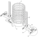
图1为本发明提出的一种用于高桥墩模板安装的设备的三维示意图;Fig. 1 is a three-dimensional schematic diagram of a device for high bridge pier formwork installation proposed by the present invention;
图2为本发明中竖板和固定板的三维图;Figure 2 is a three-dimensional view of a vertical plate and a fixed plate in the present invention;
图3为本发明中L型板的三维图;3 is a three-dimensional view of an L-shaped plate in the present invention;
图4为本发明中齿条和齿轮啮合的三维图;4 is a three-dimensional view of the meshing of the rack and gear in the present invention;
图5为本发明中驱动箱和升降箱的剖视图;Fig. 5 is the sectional view of the drive box and the lift box in the present invention;
图6为本发明中钢筋笼、第一模板和第二模板的三维图;6 is a three-dimensional view of a reinforcing bar cage, a first template and a second template in the present invention;
图7为本发明中第一模板和第二模板的三维图;7 is a three-dimensional view of a first template and a second template in the present invention;
图8为本发明实施例三提出的一种用于高桥墩模板安装的设备的三维示意图;8 is a three-dimensional schematic diagram of a device for installing a formwork for a high bridge pier proposed in
图9为本发明实施例三提出的一种用于高桥墩模板安装的设备的A部分的放大图。FIG. 9 is an enlarged view of part A of a device for installing a formwork for a high bridge pier proposed in
图中:1、钢筋笼;2、第一模板;3、L型板;4、电动安装螺栓机;5、第一连接板;6、第二连接板;7、第二模板;8、固定板;9、驱动箱;10、推板;11、电动推杆;12、竖板;13、齿条;14、滑轨;15、升降箱;16、托盘;17、卡杆;18、橡胶U型条;19、固定螺栓;20、齿轮;21、滑块;22、伺服电机;23、蓄电池;24、定位杆;25、定位槽;26、转杆;27、支撑板;28、卡孔;29、螺纹孔;30、螺纹槽;31、横板;32、螺母;33、地脚;34、万向轮;35、导杆;36、配重块。In the figure: 1. Reinforcement cage; 2. First template; 3. L-shaped plate; 4. Electric mounting bolt machine; 5. First connecting plate; 6. Second connecting plate; 7. Second template; 8. Fixing Plate; 9. Drive box; 10. Push plate; 11. Electric push rod; 12. Vertical plate; 13. Rack; 14. Slide rail; 15. Lift box; 16. Tray; 17. Clamping rod; 18. Rubber U-shaped bar; 19, fixing bolt; 20, gear; 21, slider; 22, servo motor; 23, battery; 24, positioning rod; 25, positioning groove; 26, rotating rod; 27, support plate; 28, clip Hole; 29, threaded hole; 30, threaded groove; 31, horizontal plate; 32, nut; 33, foot; 34, universal wheel; 35, guide rod; 36, counterweight.
具体实施方式Detailed ways
下面将结合本发明实施例中的附图,对本发明实施例中的技术方案进行清楚、完整地描述,显然,所描述的实施例仅仅是本发明一部分实施例,而不是全部的实施例。The technical solutions in the embodiments of the present invention will be clearly and completely described below with reference to the accompanying drawings in the embodiments of the present invention. Obviously, the described embodiments are only a part of the embodiments of the present invention, but not all of the embodiments.
实施例一Example 1
参照图1-7,一种用于高桥墩模板安装的设备,包括固定安装在地面的钢筋笼1、对称设置的两个固定板8、多个第一模板2和多个第二模板7,两个固定板8分别位于钢筋笼1的两侧,第一模板2和第二模板7均与钢筋笼1配合使用,第一模板2和第二模板7相互远离的一侧均固定连接有支撑板27,固定板8的顶部滑动连接有竖板12,固定板8的顶部固定连接有电动推杆11,电动推杆11的活塞杆固定连接有推板10,推板10的一端与竖板12的一侧固定连接,竖板12的一侧滑动连接有升降箱15,升降箱15的两侧均固定连接有相连通的驱动箱9,靠近钢筋笼1的驱动箱9的一侧设置有用于连接支撑板27的连接组件,升降箱15的内部设置有用于控制支撑板27升降的升降组件,第一模板2的侧面固定连接有对称设置的两个第一连接板5,第二模板7的侧面固定连接有对称设置的两个第二连接板6,其中一个靠近钢筋笼1的驱动箱9的两侧均固定连接有L型板3,L型板3的顶部设置有用于安装第一连接板5和第二连接板6的安装组件。1-7, a device for the installation of high bridge pier formwork, including a steel cage 1 fixedly installed on the ground, two fixed
实施例二
参照图1-7,一种用于高桥墩模板安装的设备,包括固定安装在地面的钢筋笼1、对称设置的两个固定板8、多个第一模板2和多个第二模板7,两个固定板8分别位于钢筋笼1的两侧,第一模板2和第二模板7均与钢筋笼1配合使用,第一模板2和第二模板7相互远离的一侧均固定连接有支撑板27,固定板8的顶部滑动连接有竖板12,固定板8的顶部固定连接有电动推杆11,电动推杆11的活塞杆固定连接有推板10,推板10的一端与竖板12的一侧固定连接,竖板12的一侧滑动连接有升降箱15,升降箱15的两侧均固定连接有相连通的驱动箱9,靠近钢筋笼1的驱动箱9的一侧设置有用于连接支撑板27的连接组件,连接组件包括固定连接在驱动箱9一侧的托盘16,托盘16的顶部固定连接有对称设置的两个卡杆17,支撑板27的内部开设有对称设置的两个卡孔28,卡杆17与卡孔28相卡合,用于连接支撑板27,不再需要人工搬运模板,降低工人的工作量,升降箱15的内部设置有用于控制支撑板27升降的升降组件,升降组件包括分别固定连接在竖板12两侧的两个齿条13,驱动箱9的一侧内壁转动连接有转杆26,转杆26的外壁固定套设有与齿条13相啮合的齿轮20,两个齿轮20相互靠近的一侧均延伸至驱动箱9的外部,用于调节模板的高度,进而不再需要大型起吊器械提升模板,降低成本,第一模板2的侧面固定连接有对称设置的两个第一连接板5,第二模板7的侧面固定连接有对称设置的两个第二连接板6,其中一个靠近钢筋笼1的驱动箱9的两侧均固定连接有L型板3,L型板3的顶部设置有用于安装第一连接板5和第二连接板6的安装组件,安装组件包括固定连接在L型板3顶部的电动安装螺栓机4,电动安装螺栓机4的输出轴上设置有固定螺栓19,L型板3的顶部固定连接有橡胶U型条18,第一连接板5的内部开设有与固定螺栓19相配合的螺纹孔29,第二连接板6靠近L型板3的一侧开设有与固定螺栓19相配合的螺纹槽30,用于自动安装模板,不再需要人工安装,保证了工人的人身安全,升降箱15的一侧内壁固定连接有对称设置的两个伺服电机22,两个伺服电机22的输出轴分别与两个转杆26的一端固定连接,升降箱15的内部设置有蓄电池23,两个伺服电机22均与蓄电池23电性连接,自动实现升降功能,并且不需要外接电线,便于安装,第一模板2和第二模板7的顶部均固定连接有多个定位杆24,第一模板2和第二模板7的底部均开设有多个与定位杆24相卡合的定位槽25,保证上下两层模板之间的稳定性,竖板12的一侧固定连接有滑轨14,升降箱15的一侧固定连接有滑块21,滑块21与滑轨14滑动连接,用于保证模板上升和下降过程的稳定。1-7, a device for the installation of high bridge pier formwork, including a steel cage 1 fixedly installed on the ground, two fixed
实施例三
参照图1-9,本实施例三在实施例二基础上的改进为:固定板8的顶部固定安装有导杆35,导杆35的外壁上套设有多个配重块36,根据第一模板2和第二模板7的具体重量来增加配重块36的数量,可以使固定板8两端受力平衡,固定板8的顶部四角位置均固定安装有横板31,横板31的底部固定安装有万向轮34,横板31的顶部一侧贯穿螺纹连接有地脚33,地脚33的外壁上螺纹连接有两个螺母32,两个螺母32相互靠近的一侧分别与横板31的顶部和底部相抵触,固定板8的四角均设置有地脚33,且通过横板31向外延伸,可以增加受力面积,增加装置的稳定性,在使用完成后,旋松螺母32,并将地脚33升起,则万向轮34会与地面接触,则可以利用万向轮34来移动本装置。1-9, the improvement of the third embodiment on the basis of the second embodiment is: a
一种用于高桥墩模板安装的设备的使用方法,包括以下步骤:A method for using an apparatus for installing a formwork for a high bridge pier, comprising the following steps:
S1、将两个固定板固定在合适的位置,启动伺服电机,伺服电机的输出轴带动转杆转动,转杆带动齿轮转动,齿轮与齿条相啮合,由于齿条是固定的,此时驱动箱和升降箱竖直向上移动,驱动箱带动托盘竖直向上移动,托盘带动卡杆竖直向上移动,卡杆与卡孔相卡合,此时可以带动第一模板和第二模板移动;启动电动推杆,电动推杆的活塞杆带动推板横向移动,推板推动竖板横向移动,竖板带动升降箱横向移动,进而将第一模板和第二模板推动至钢盘笼外壁最底层的位置,并使得第一连接板和第二连接板相抵触,此时启动电动安装螺栓机,电动安装螺栓机带动固定螺栓与螺纹孔和螺纹槽螺纹连接,完成第一模板和第二模板的安装;S1. Fix the two fixing plates in the proper position, start the servo motor, the output shaft of the servo motor drives the rotating rod to rotate, the rotating rod drives the gear to rotate, and the gear meshes with the rack. Since the rack is fixed, the drive The box and the lift box move vertically upward, the drive box drives the tray to move vertically upward, the tray drives the clamping rod to move vertically upward, and the clamping rod is engaged with the clamping hole, at this time, the first template and the second template can be driven to move; start Electric push rod, the piston rod of the electric push rod drives the push plate to move laterally, the push plate pushes the vertical plate to move laterally, the vertical plate drives the lift box to move laterally, and then pushes the first template and the second template to the bottom of the outer wall of the steel plate cage. position, and make the first connecting plate and the second connecting plate conflict, at this time start the electric installation bolt machine, the electric installation bolt machine drives the fixing bolts to be threadedly connected with the threaded holes and threaded grooves to complete the installation of the first template and the second template. ;
S2、伺服电机反转,驱动箱和升降箱竖直向下移动,使得卡杆与卡孔解除卡合状态;S2. The servo motor is reversed, and the drive box and the lift box move vertically downward, so that the clamping rod and the clamping hole are released from the clamping state;
S3、重复S1、S2操作,安装第二层第一模板和第二模板,并使其上一层第一模板和第二模板顶部的多个定位杆与其底部的多个定位槽一一对应卡合;S3. Repeat the operations of S1 and S2, install the first template and the second template on the second layer, and make the positioning rods on the top of the first template and the second template on the upper layer correspond one-to-one with the positioning grooves on the bottom. combine;
S4、重复上述操作,完成每一层第一模板和第二模板的安装。S4. Repeat the above operations to complete the installation of the first template and the second template for each layer.
工作原理:在使用时,将两个固定板8固定在合适的位置,启动伺服电机22,伺服电机22的输出轴带动转杆26转动,转杆26带动齿轮20转动,齿轮20与齿条13相啮合,由于齿条13是固定的,此时驱动箱9和升降箱15竖直向上移动,驱动箱9带动托盘16竖直向上移动,托盘16带动卡杆17竖直向上移动,卡杆17与卡孔28相卡合,此时可以带动第一模板2和第二模板7移动,启动电动推杆11,电动推杆11的活塞杆带动推板10横向移动,推板10推动竖板12横向移动,竖板12带动升降箱15横向移动,进而将第一模板2和第二模板7推动至合适的位置,并使得第一连接板5和第二连接板6相抵触,此时启动电动安装螺栓机4,电动安装螺栓机4带动固定螺栓19与螺纹孔29和螺纹槽30螺纹连接,完成第一模板2和第二模板7的安装,此时伺服电机22反转,驱动箱9和升降箱15竖直向下移动,使得卡杆17与卡孔28解除卡合状态,重复上述操作,并利用伺服电机22的正转,可以带动第一模板2和第二模板7上升至不同的高度,使得整个过程不需要人工,降低了工人的工作量,每次安装新的第一模板2和第二模板7时,利用橡胶U型条18固定新的固定螺栓19,保证第一模板2和第二模板7的正常安装。Working principle: when in use, fix the two fixing
当然,如本领域技术人员所熟知的,伺服电机22、蓄电池23、和电动安装螺栓机4的工作原理和接线方法均属于常规手段或者本领域的公知常识,在此就不再赘述,本领域技术人员可以根据其需要或者便利进行任意的选配。Of course, as known to those skilled in the art, the working principles and wiring methods of the
以上所述,仅为本发明较佳的具体实施方式,但本发明的保护范围并不局限于此,任何熟悉本技术领域的技术人员在本发明揭露的技术范围内,根据本发明的技术方案及其发明构思加以等同替换或改变,都应涵盖在本发明的保护范围之内。The above description is only a preferred embodiment of the present invention, but the protection scope of the present invention is not limited to this. The equivalent replacement or change of the inventive concept thereof shall be included within the protection scope of the present invention.
Claims (7)
Priority Applications (1)
| Application Number | Priority Date | Filing Date | Title |
|---|---|---|---|
| CN202210139398.1A CN114481848B (en) | 2022-02-16 | 2022-02-16 | A device for installing high bridge pier formwork and a method for using the same |
Applications Claiming Priority (1)
| Application Number | Priority Date | Filing Date | Title |
|---|---|---|---|
| CN202210139398.1A CN114481848B (en) | 2022-02-16 | 2022-02-16 | A device for installing high bridge pier formwork and a method for using the same |
Publications (2)
| Publication Number | Publication Date |
|---|---|
| CN114481848A true CN114481848A (en) | 2022-05-13 |
| CN114481848B CN114481848B (en) | 2025-03-18 |
Family
ID=81480592
Family Applications (1)
| Application Number | Title | Priority Date | Filing Date |
|---|---|---|---|
| CN202210139398.1A Active CN114481848B (en) | 2022-02-16 | 2022-02-16 | A device for installing high bridge pier formwork and a method for using the same |
Country Status (1)
| Country | Link |
|---|---|
| CN (1) | CN114481848B (en) |
Cited By (2)
| Publication number | Priority date | Publication date | Assignee | Title |
|---|---|---|---|---|
| CN116717081A (en) * | 2023-07-20 | 2023-09-08 | 新疆兵团城建集团有限公司 | BDF ribbed steel mesh hollow member hollow floor construction device |
| CN116772814A (en) * | 2023-08-18 | 2023-09-19 | 贵州省公路工程集团有限公司 | Steel reinforcement cage perpendicularity detection device and method with positioning and adjusting functions |
Citations (12)
| Publication number | Priority date | Publication date | Assignee | Title |
|---|---|---|---|---|
| ES2035811T1 (en) * | 1991-05-16 | 1993-05-01 | Strickland Industries, Inc. | INTERIOR CORNER MOLD. |
| CN105401529A (en) * | 2015-12-18 | 2016-03-16 | 辽宁科技学院 | Full-automatic bridge pier template lifting and locating device and method |
| CN207863472U (en) * | 2017-05-23 | 2018-09-14 | 重庆交通职业学院 | A kind of building template link |
| CN208039825U (en) * | 2018-01-09 | 2018-11-02 | 苏州荔记得机械工程科技有限公司 | A kind of concrete column template |
| CN208981760U (en) * | 2018-08-07 | 2019-06-14 | 浙江汇景建筑科技有限公司 | A kind of aluminum alloy mould plate support device convenient for adjusting |
| CN110439276A (en) * | 2019-07-31 | 2019-11-12 | 深圳市惠深博越智慧建造科技有限公司 | A kind of column template installation method |
| CN110748158A (en) * | 2019-10-09 | 2020-02-04 | 石丽 | Concrete formwork structure and construction method |
| CN110952461A (en) * | 2019-12-23 | 2020-04-03 | 沈靖林 | Construction method for viaduct bridge pier |
| CN112411988A (en) * | 2020-11-09 | 2021-02-26 | 厦门安科科技有限公司 | Novel attached lifting scaffold |
| CN212897555U (en) * | 2020-07-16 | 2021-04-06 | 苏州熠冉智能科技有限公司 | Electric creeping formwork device for building construction |
| CN213837730U (en) * | 2020-12-03 | 2021-07-30 | 中建四局第三建设有限公司 | Constructional column formwork reinforcing apparatus with feeding function |
| CN113417455A (en) * | 2021-06-09 | 2021-09-21 | 中交第四航务工程局有限公司 | Self-reinforcing supporting rod for slip form construction |
-
2022
- 2022-02-16 CN CN202210139398.1A patent/CN114481848B/en active Active
Patent Citations (12)
| Publication number | Priority date | Publication date | Assignee | Title |
|---|---|---|---|---|
| ES2035811T1 (en) * | 1991-05-16 | 1993-05-01 | Strickland Industries, Inc. | INTERIOR CORNER MOLD. |
| CN105401529A (en) * | 2015-12-18 | 2016-03-16 | 辽宁科技学院 | Full-automatic bridge pier template lifting and locating device and method |
| CN207863472U (en) * | 2017-05-23 | 2018-09-14 | 重庆交通职业学院 | A kind of building template link |
| CN208039825U (en) * | 2018-01-09 | 2018-11-02 | 苏州荔记得机械工程科技有限公司 | A kind of concrete column template |
| CN208981760U (en) * | 2018-08-07 | 2019-06-14 | 浙江汇景建筑科技有限公司 | A kind of aluminum alloy mould plate support device convenient for adjusting |
| CN110439276A (en) * | 2019-07-31 | 2019-11-12 | 深圳市惠深博越智慧建造科技有限公司 | A kind of column template installation method |
| CN110748158A (en) * | 2019-10-09 | 2020-02-04 | 石丽 | Concrete formwork structure and construction method |
| CN110952461A (en) * | 2019-12-23 | 2020-04-03 | 沈靖林 | Construction method for viaduct bridge pier |
| CN212897555U (en) * | 2020-07-16 | 2021-04-06 | 苏州熠冉智能科技有限公司 | Electric creeping formwork device for building construction |
| CN112411988A (en) * | 2020-11-09 | 2021-02-26 | 厦门安科科技有限公司 | Novel attached lifting scaffold |
| CN213837730U (en) * | 2020-12-03 | 2021-07-30 | 中建四局第三建设有限公司 | Constructional column formwork reinforcing apparatus with feeding function |
| CN113417455A (en) * | 2021-06-09 | 2021-09-21 | 中交第四航务工程局有限公司 | Self-reinforcing supporting rod for slip form construction |
Cited By (4)
| Publication number | Priority date | Publication date | Assignee | Title |
|---|---|---|---|---|
| CN116717081A (en) * | 2023-07-20 | 2023-09-08 | 新疆兵团城建集团有限公司 | BDF ribbed steel mesh hollow member hollow floor construction device |
| CN116717081B (en) * | 2023-07-20 | 2024-04-30 | 新疆兵团城建集团有限公司 | BDF ribbed steel mesh hollow member hollow floor construction device |
| CN116772814A (en) * | 2023-08-18 | 2023-09-19 | 贵州省公路工程集团有限公司 | Steel reinforcement cage perpendicularity detection device and method with positioning and adjusting functions |
| CN116772814B (en) * | 2023-08-18 | 2023-10-17 | 贵州省公路工程集团有限公司 | Steel reinforcement cage perpendicularity detection device and method with positioning and adjusting functions |
Also Published As
| Publication number | Publication date |
|---|---|
| CN114481848B (en) | 2025-03-18 |
Similar Documents
| Publication | Publication Date | Title |
|---|---|---|
| CN201679222U (en) | Double mast climbing work platform | |
| CN114481848A (en) | Equipment for installing high pier template and using method thereof | |
| CN207944689U (en) | A kind of architectural engineering Multifunctional lift scaffold | |
| CN110700418B (en) | Construction process for mounting laminated slab by matching laminated slab mounting trolley with tower crane | |
| CN104150353A (en) | Liftable and detachable bridge crane | |
| WO2023184882A1 (en) | Material lifting device | |
| CN110714611A (en) | Light climbing formwork steel frame system | |
| CN212802516U (en) | High-rise building climbing pouring system | |
| CN216739320U (en) | High pier automatic installation template equipment | |
| CN116675140B (en) | Concrete prefabricated component lifts and aligns installation device | |
| TWM517757U (en) | Lift type supporting system for bridge superstructure | |
| CN214360123U (en) | Small-size lift is used in engineering construction | |
| CN211775572U (en) | Climbing scaffold with unloading platform | |
| CN210369893U (en) | Light-duty creeping formwork system of lead screw promotion | |
| CN210366899U (en) | a lift platform | |
| CN106006461A (en) | Lifting platform for hidden maintenance of motorcycles | |
| CN221321943U (en) | Balance adjusting mechanism of stereo garage | |
| CN112576048A (en) | Assembly type building spandrel girder handling mounting system | |
| CN220928826U (en) | House reinforcing structure | |
| CN218805960U (en) | Disk cabinet transportation and installation equipment | |
| CN218371549U (en) | Concrete slab construction conveying equipment | |
| CN212835920U (en) | Movable electric lifting scaffold | |
| CN218289492U (en) | Clamping mechanism of prefabricated wallboard turning device | |
| CN216105701U (en) | Hoisting device for engineering reinforcement construction | |
| CN218758592U (en) | Scaffold for construction of large storage tank bearing platform |
Legal Events
| Date | Code | Title | Description |
|---|---|---|---|
| PB01 | Publication | ||
| PB01 | Publication | ||
| SE01 | Entry into force of request for substantive examination | ||
| SE01 | Entry into force of request for substantive examination | ||
| GR01 | Patent grant |