CN114466962A - Set of panels comprising flexible grooves - Google Patents
Set of panels comprising flexible grooves Download PDFInfo
- Publication number
- CN114466962A CN114466962A CN202080067123.0A CN202080067123A CN114466962A CN 114466962 A CN114466962 A CN 114466962A CN 202080067123 A CN202080067123 A CN 202080067123A CN 114466962 A CN114466962 A CN 114466962A
- Authority
- CN
- China
- Prior art keywords
- panel
- edge
- distance
- locking
- range
- Prior art date
- Legal status (The legal status is an assumption and is not a legal conclusion. Google has not performed a legal analysis and makes no representation as to the accuracy of the status listed.)
- Pending
Links
Images


Classifications
-
- E—FIXED CONSTRUCTIONS
- E04—BUILDING
- E04F—FINISHING WORK ON BUILDINGS, e.g. STAIRS, FLOORS
- E04F15/00—Flooring
- E04F15/02—Flooring or floor layers composed of a number of similar elements
- E04F15/02038—Flooring or floor layers composed of a number of similar elements characterised by tongue and groove connections between neighbouring flooring elements
-
- E—FIXED CONSTRUCTIONS
- E04—BUILDING
- E04F—FINISHING WORK ON BUILDINGS, e.g. STAIRS, FLOORS
- E04F15/00—Flooring
- E04F15/02—Flooring or floor layers composed of a number of similar elements
- E04F15/02005—Construction of joints, e.g. dividing strips
- E04F15/02033—Joints with beveled or recessed upper edges
-
- E—FIXED CONSTRUCTIONS
- E04—BUILDING
- E04F—FINISHING WORK ON BUILDINGS, e.g. STAIRS, FLOORS
- E04F15/00—Flooring
- E04F15/02—Flooring or floor layers composed of a number of similar elements
- E04F15/04—Flooring or floor layers composed of a number of similar elements only of wood or with a top layer of wood, e.g. with wooden or metal connecting members
-
- E—FIXED CONSTRUCTIONS
- E04—BUILDING
- E04F—FINISHING WORK ON BUILDINGS, e.g. STAIRS, FLOORS
- E04F15/00—Flooring
- E04F15/02—Flooring or floor layers composed of a number of similar elements
- E04F15/10—Flooring or floor layers composed of a number of similar elements of other materials, e.g. fibrous or chipped materials, organic plastics, magnesite tiles, hardboard, or with a top layer of other materials
- E04F15/102—Flooring or floor layers composed of a number of similar elements of other materials, e.g. fibrous or chipped materials, organic plastics, magnesite tiles, hardboard, or with a top layer of other materials of fibrous or chipped materials, e.g. bonded with synthetic resins
-
- E—FIXED CONSTRUCTIONS
- E04—BUILDING
- E04F—FINISHING WORK ON BUILDINGS, e.g. STAIRS, FLOORS
- E04F15/00—Flooring
- E04F15/02—Flooring or floor layers composed of a number of similar elements
- E04F15/10—Flooring or floor layers composed of a number of similar elements of other materials, e.g. fibrous or chipped materials, organic plastics, magnesite tiles, hardboard, or with a top layer of other materials
- E04F15/105—Flooring or floor layers composed of a number of similar elements of other materials, e.g. fibrous or chipped materials, organic plastics, magnesite tiles, hardboard, or with a top layer of other materials of organic plastics with or without reinforcements or filling materials
-
- E—FIXED CONSTRUCTIONS
- E04—BUILDING
- E04F—FINISHING WORK ON BUILDINGS, e.g. STAIRS, FLOORS
- E04F2201/00—Joining sheets or plates or panels
- E04F2201/01—Joining sheets, plates or panels with edges in abutting relationship
- E04F2201/0138—Joining sheets, plates or panels with edges in abutting relationship by moving the sheets, plates or panels perpendicular to the main plane
- E04F2201/0146—Joining sheets, plates or panels with edges in abutting relationship by moving the sheets, plates or panels perpendicular to the main plane with snap action of the edge connectors
-
- E—FIXED CONSTRUCTIONS
- E04—BUILDING
- E04F—FINISHING WORK ON BUILDINGS, e.g. STAIRS, FLOORS
- E04F2201/00—Joining sheets or plates or panels
- E04F2201/02—Non-undercut connections, e.g. tongue and groove connections
- E04F2201/023—Non-undercut connections, e.g. tongue and groove connections with a continuous tongue or groove
-
- E—FIXED CONSTRUCTIONS
- E04—BUILDING
- E04F—FINISHING WORK ON BUILDINGS, e.g. STAIRS, FLOORS
- E04F2201/00—Joining sheets or plates or panels
- E04F2201/04—Other details of tongues or grooves
- E04F2201/041—Tongues or grooves with slits or cuts for expansion or flexibility
-
- E—FIXED CONSTRUCTIONS
- E04—BUILDING
- E04F—FINISHING WORK ON BUILDINGS, e.g. STAIRS, FLOORS
- E04F2201/00—Joining sheets or plates or panels
- E04F2201/04—Other details of tongues or grooves
- E04F2201/042—Other details of tongues or grooves with grooves positioned on the rear-side of the panel
Landscapes
- Engineering & Computer Science (AREA)
- Architecture (AREA)
- Civil Engineering (AREA)
- Structural Engineering (AREA)
- Life Sciences & Earth Sciences (AREA)
- Wood Science & Technology (AREA)
- Finishing Walls (AREA)
- Connection Of Plates (AREA)
Abstract
一组镶板,包括第一和第二镶板1、2,以及用于通过这些镶板的竖直相对位移进行组装的机械锁定装置。锁定条7从第一镶板的第一边缘11沿平行于第一镶板的第一和第二镶板表面的方向延伸。锁定条包括锁定条边缘以及第一和第二锁定条表面72、73,其分别在与第一和第二镶板表面的方向基本对应的方向上延伸。锁定条的锁定元件3与第二镶板的第二边缘21处的锁定沟槽4配合以用于在平行于第一镶板表面的方向上锁定。相对的边缘分别包括用于竖直锁定的相配合的榫舌和榫舌沟槽5、6。柔性沟槽8从第一锁定条表面/第一边缘的过渡部与第一镶板表面成一定角度α延伸到第一镶板中。此外,该组镶板具有厚度Q并且包括以宽度T设置的柔性沟槽,以便Q与T的比率在0.05‑0.40的区间内。
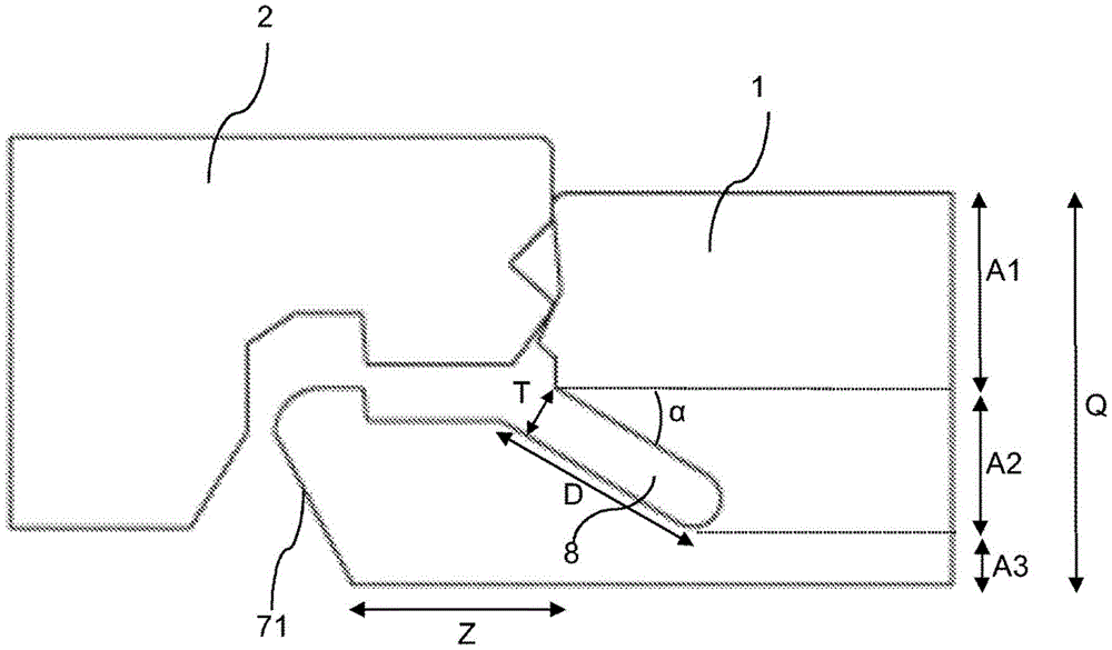
A set of panels comprising first and second panels 1, 2 and mechanical locking means for assembly by vertical relative displacement of these panels. The locking strip 7 extends from the first edge 11 of the first panel in a direction parallel to the first and second panel surfaces of the first panel. The locking strip includes a locking strip edge and first and second locking strip surfaces 72, 73 extending in directions substantially corresponding to the directions of the first and second panel surfaces, respectively. The locking elements 3 of the locking strip cooperate with the locking grooves 4 at the second edge 21 of the second panel for locking in a direction parallel to the surface of the first panel. The opposite edges respectively comprise cooperating tongues and tongue grooves 5, 6 for vertical locking. The flexible groove 8 extends into the first panel from the transition of the first locking strip surface/first edge at an angle α to the first panel surface. Furthermore, the set of panels has a thickness Q and includes flexible grooves arranged with a width T so that the ratio of Q to T is in the interval 0.05-0.40.
Description
技术领域technical field
本发明的实施例涉及配置成利用机械锁定装置锁定在一起的镶板。这些镶板可以是配置成锁定在一起以获得地板产品的地板块。Embodiments of the present invention relate to panels configured to be locked together using mechanical locking means. The panels may be floorboards configured to be locked together to obtain a flooring product.
背景技术Background technique
构造成通过竖直位移进行组装并在竖直方向和水平方向锁定在一起的镶板是已知的。这种镶板在例如WO 2018/063047中公开。榫舌-沟槽连接结构将第一镶板的第一边缘锁定到第二镶板的第二边缘。第一边缘和第二边缘还包括锁定元件,该锁定元件配置为与锁定沟槽协作,用于在竖直方向和水平方向上实现锁定。Panels configured to be assembled by vertical displacement and locked together in vertical and horizontal directions are known. Such panels are disclosed, for example, in WO 2018/063047. The tongue-and-groove connection locks the first edge of the first panel to the second edge of the second panel. The first edge and the second edge also include locking elements configured to cooperate with the locking grooves for effecting locking in the vertical and horizontal directions.
以上对各种已知方面的描述是申请人对这些方面的特征化表述,并非承认任何以上描述被认为是现有技术。The above description of various known aspects is the applicant's characterization of those aspects and is not an admission that any of the above description is admitted to be prior art.
本发明的实施例解决了提供易于组装的镶板的需求。Embodiments of the present invention address the need to provide panels that are easy to assemble.
发明内容SUMMARY OF THE INVENTION
本发明的某些方面的一个目的是提供对上述技术和已知技术的改进。It is an object of certain aspects of the present invention to provide improvements over the above-described techniques and known techniques.
本发明的至少某些方面的另一个目的是便于镶板的组装,所述镶板构造成通过竖直位移或倾角运动(angling motion)进行组装并在竖直方向和水平方向锁定在一起。Another object of at least some aspects of the present invention is to facilitate the assembly of panels configured to be assembled by vertical displacement or angling motion and locked together vertically and horizontally.
本发明的至少某些方面的另一个目的是便于镶板的组装,所述镶板构造成以减少组装镶板时需要人施加的力和冲击的方式进行组装。Another object of at least some aspects of the present invention is to facilitate the assembly of panels that are configured to be assembled in a manner that reduces the force and impact required by a person to assemble the panels.
根据第一方面,提供了一组镶板,包括第一镶板、第二镶板和用于将第一镶板锁定到第二镶板的机械锁定装置,机械锁定装置配置用于通过第二镶板相对于第一镶板在竖直方向上的位移进行组装以获得第一镶板和第二镶板的锁定位置,其中第一镶板包括第一边缘、第一镶板表面和第二镶板表面,并且第二镶板包括第二边缘,其中机械锁定装置包括从第一边缘在平行于第一和第二镶板表面的方向上延伸的锁定条,其中锁定条包括锁定条边缘,其中锁定条包括在与第一镶板的第一镶板表面的方向基本对应的方向上延伸的第一锁定条表面,其中所述锁定条包括第二锁定条表面,所述第二锁定条表面在与所述第一镶板的所述第二镶板表面的方向基本对应的方向上延伸,其中所述锁定条包括锁定元件,所述锁定元件配置为与所述第二镶板的第二边缘处的锁定沟槽协作,以用于在平行于所述第一镶板表面的方向上实现锁定,其中所述第一或第二边缘中的一者包括榫舌,所述榫舌构造成与所述第一或第二边缘中的另一者处的榫舌沟槽配合,以用于在竖直方向上锁定,其特征在于,所述机械锁定装置包括柔性沟槽,所述柔性沟槽从所述第一锁定条表面和所述第一边缘之间的过渡部与所述第一镶板表面成一定角度α延伸到所述第一镶板中,并且锁定条构造成在组装过程中通过改变柔性沟槽的形状而屈伸变形(flex),从而增加锁定条在组装过程中的柔性。According to a first aspect, there is provided a set of panels comprising a first panel, a second panel and a mechanical locking device for locking the first panel to the second panel, the mechanical locking device being configured to pass the second panel The panels are assembled relative to vertical displacement of the first panel to obtain a locked position of the first panel and the second panel, wherein the first panel includes a first edge, a first panel surface and a second panel a panel surface, and the second panel includes a second edge, wherein the mechanical locking means includes a locking bar extending from the first edge in a direction parallel to the first and second panel surfaces, wherein the locking bar includes a locking bar edge, wherein the locking bar includes a first locking bar surface extending in a direction substantially corresponding to the direction of the first panel surface of the first panel, wherein the locking bar includes a second locking bar surface, the second locking bar surface extending in a direction substantially corresponding to the direction of the second panel surface of the first panel, wherein the locking bar includes a locking element configured to align with the second panel surface of the second panel Locking grooves at the edges cooperate for locking in a direction parallel to the first panel surface, wherein one of the first or second edges comprises a tongue configured to cooperating with a tongue groove at the other of the first or second edge for locking in a vertical direction, characterized in that the mechanical locking means comprises a flexible groove, the flexible groove A slot extends into the first panel from the transition between the first locking strip surface and the first edge at an angle a to the first panel surface, and the locking strip is configured to be used during assembly By changing the shape of the flexible groove and flexing and stretching, the flexibility of the locking strip during the assembly process is increased.
根据另一方面,提供了一组镶板,包括第一镶板、第二镶板和用于将第一镶板锁定到第二镶板的机械锁定装置,机械锁定装置配置用于通过第二镶板相对于第一镶板在竖直方向上的位移进行组装以获得第一镶板和第二镶板的锁定位置,其中第一镶板包括第一边缘、第一镶板表面和第二镶板表面,并且第二镶板包括第二边缘,其中机械锁定装置包括从第一边缘在平行于第一和第二镶板表面的方向上延伸的锁定条,其中锁定条包括锁定条边缘,其中锁定条包括在与第一镶板的第一镶板表面的方向基本对应的方向上延伸的第一锁定条表面,其中锁定条包括在与第一镶板的第二镶板表面的方向基本对应的方向上延伸的第二锁定条表面,其中锁定条包括锁定元件,所述锁定元件构造为与第二镶板的第二边缘处的锁定沟槽相配合,以用于在平行于第一镶板表面的方向上锁定,其中第一或第二边缘中的一者包括榫舌,所述榫舌构造成与第一或第二边缘中的另一者处的榫舌沟槽相配合,以用于在竖直方向上锁定,其特征在于,所述机械锁定装置包括柔性沟槽,所述柔性沟槽从所述第一锁定条表面和所述第一边缘之间的过渡部与第一镶板表面成一定角度α延伸到所述第一镶板中,其中所述角度α在大约0°到大约30°的范围内,优选地在大约0°到大约20°的范围内,更优选地在大约0°到大约10°的范围内,甚至更优选地在大约0°到大约5°的范围内,并且锁定条构造成在组装期间通过改变柔性沟槽的形状而屈伸变形,因此增加了锁定条在组装期间的柔性。According to another aspect, there is provided a set of panels comprising a first panel, a second panel and a mechanical locking device for locking the first panel to the second panel, the mechanical locking device being configured to pass the second panel The panels are assembled relative to vertical displacement of the first panel to obtain a locked position of the first panel and the second panel, wherein the first panel includes a first edge, a first panel surface and a second panel a panel surface, and the second panel includes a second edge, wherein the mechanical locking means includes a locking bar extending from the first edge in a direction parallel to the first and second panel surfaces, wherein the locking bar includes a locking bar edge, wherein the locking bar comprises a first locking bar surface extending in a direction substantially corresponding to the direction of the first panel surface of the first panel, wherein the locking bar comprises a direction substantially corresponding to the direction of the second panel surface of the first panel a second locking bar surface extending in a corresponding direction, wherein the locking bar includes locking elements configured to mate with locking grooves at the second edge of the second panel for locking in the direction of the panel surface, wherein one of the first or second edge includes a tongue configured to mate with a tongue groove at the other of the first or second edge, for locking in a vertical direction, wherein the mechanical locking means comprises a flexible groove extending from the transition between the first locking bar surface and the first edge to the first A panel surface extends into the first panel at an angle α, wherein the angle α is in the range of about 0° to about 30°, preferably in the range of about 0° to about 20°, more Preferably in the range of about 0° to about 10°, even more preferably in the range of about 0° to about 5°, and the locking strip is configured to flex during assembly by changing the shape of the flexible channel, thus Increased flexibility of the locking strip during assembly.
根据一个方面,柔性沟槽的开口具有宽度T。According to one aspect, the opening of the flexible channel has a width T.
根据一个方面,柔性沟槽的开口的宽度T在大约0.6mm至大约2.5mm的范围内,优选地在大约0.8mm至大约2.0mm的范围内,更优选地为1.6mm。According to one aspect, the width T of the opening of the flexible channel is in the range of about 0.6 mm to about 2.5 mm, preferably in the range of about 0.8 mm to about 2.0 mm, more preferably 1.6 mm.
根据一个方面,柔性沟槽的开口的宽度T与第一镶板表面和第二镶板表面之间的距离Q之间的比率在大约0.05至大约0.4的范围内,优选地大约0.1至大约0.3,更优选地大约0.15至大约0.2。According to one aspect, the ratio between the width T of the opening of the flexible channel and the distance Q between the first and second panel surfaces is in the range of about 0.05 to about 0.4, preferably about 0.1 to about 0.3 , more preferably from about 0.15 to about 0.2.
根据一个方面,柔性沟槽的深度D在大约2.5mm至大约15mm的范围内,优选地大约4mm至大约12mm,更优选地大约5mm至大约10mm,甚至更优选地大约7mm。According to one aspect, the depth D of the flexible groove is in the range of about 2.5mm to about 15mm, preferably about 4mm to about 12mm, more preferably about 5mm to about 10mm, even more preferably about 7mm.
根据一个方面,柔性沟槽的深度D与柔性沟槽的宽度T之间的比率为大约2至大约10,优选地为大约3至大约7,更优选地为大约4。According to one aspect, the ratio between the depth D of the flexible trench and the width T of the flexible trench is about 2 to about 10, preferably about 3 to about 7, more preferably about 4.
根据一个方面,柔性沟槽具有底部。According to one aspect, the flexible channel has a bottom.
根据一个方面,柔性沟槽的底部的长度M与柔性沟槽的开口的宽度T之间的比率在大约0.5至大约2的范围内,优选地大约0.8至大约1.4,更优选地大约1至大约1.25。According to one aspect, the ratio between the length M of the bottom of the flexible channel and the width T of the opening of the flexible channel is in the range of about 0.5 to about 2, preferably about 0.8 to about 1.4, more preferably about 1 to about 1.25.
根据一个方面,第一锁定条边缘定位在距第一边缘一定距离Z处,其中Z在大约4mm至大约12mm的范围内,优选地大约6mm至大约9mm,更优选地大约7.5mm至大约8.5mm。According to one aspect, the first locking bar edge is positioned at a distance Z from the first edge, wherein Z is in the range of about 4mm to about 12mm, preferably about 6mm to about 9mm, more preferably about 7.5mm to about 8.5mm .
根据一个方面,距离Z与柔性沟槽的开口的宽度T之间的比率在大约2到大约10的范围内,优选地大约4到大约6,更优选地为大约5。According to one aspect, the ratio between the distance Z and the width T of the opening of the flexible channel is in the range of about 2 to about 10, preferably about 4 to about 6, more preferably about 5.
根据一个方面,柔性沟槽具有长度L。According to one aspect, the flexible channel has a length L.
根据一个方面,第一镶板包括第三边缘和第四边缘,第三边缘在距第四边缘一定距离TL处。According to one aspect, the first panel comprises a third edge and a fourth edge, the third edge being at a distance TL from the fourth edge.
根据一个方面,柔性沟槽的长度L从第一镶板的第三边缘延伸到第一镶板的第四边缘。According to one aspect, the length L of the flexible channel extends from the third edge of the first panel to the fourth edge of the first panel.
根据一个方面,柔性沟槽具有第五边缘和第六边缘,第五边缘位于距第三边缘一定距离X处,第六边缘位于距第四边缘一定距离X处。According to one aspect, the flexible channel has a fifth edge located a distance X from the third edge and a sixth edge located a distance X from the fourth edge.
根据一个方面,距离X在大约1mm到大约30mm的范围内,优选地大约5mm到大约20mm,更优选地为大约10mm。According to one aspect, the distance X is in the range of about 1 mm to about 30 mm, preferably about 5 mm to about 20 mm, more preferably about 10 mm.
根据一个方面,柔性沟槽的底部是基本拱形的。According to one aspect, the bottom of the flexible channel is substantially arcuate.
根据一个方面,柔性沟槽的底部是基本三角形的。According to one aspect, the bottom of the flexible channel is substantially triangular.
根据一个方面,柔性沟槽的横截面形状为基本长方形或正方形。According to one aspect, the cross-sectional shape of the flexible channel is substantially rectangular or square.
根据一个方面,连接到第一边缘的柔性沟槽的开口位于在竖直方向上距第一镶板表面一定距离A1处。According to one aspect, the opening of the flexible channel connected to the first edge is located at a distance A1 in the vertical direction from the surface of the first panel.
根据一个方面,距离A1在大约2mm至大约7mm的范围内,优选地大约3mm至大约6mm,更优选地大约4mm至大约5mm。According to one aspect, the distance A1 is in the range of about 2 mm to about 7 mm, preferably about 3 mm to about 6 mm, more preferably about 4 mm to about 5 mm.
根据一个方面,柔性沟槽的底部位于在竖直方向上距第二镶板表面一定距离A3处。According to one aspect, the bottom of the flexible channel is located at a distance A3 in the vertical direction from the second panel surface.
根据一个方面,距离A3在大约1mm至大约7mm的范围内,优选地大约1.25mm至大约3mm,更优选地大约1.5mm至大约2mm。According to one aspect, the distance A3 is in the range of about 1 mm to about 7 mm, preferably about 1.25 mm to about 3 mm, more preferably about 1.5 mm to about 2 mm.
根据一个方面,柔性沟槽在基本垂直于第二镶板表面的方向上延伸一定距离A2,其中A2等于距离Q减去距离A1减去距离A3((Q)-(A1)-(A3))。According to one aspect, the flexible channel extends a distance A2 in a direction substantially perpendicular to the surface of the second panel, wherein A2 is equal to distance Q minus distance A1 minus distance A3 ((Q)-(A1)-(A3)) .
根据一个方面,距离A2与距离A3之间的比率为大约0.8至大约3,优选大约1至大约2,更优选大约1.25至大约1.75。According to one aspect, the ratio between distance A2 and distance A3 is about 0.8 to about 3, preferably about 1 to about 2, more preferably about 1.25 to about 1.75.
根据一个方面,距离A2与距离A1之间的比率为大约0.3至大约1.2,优选为大约0.4至大约0.9,更优选为大约0.5。According to one aspect, the ratio between distance A2 and distance A1 is about 0.3 to about 1.2, preferably about 0.4 to about 0.9, more preferably about 0.5.
根据一个方面,距离A2加上距离A3的总和与距离Q之间的比率(((A2)+(A3))/(Q))为大约0.2至大约0.5,优选地为大约0.25至大约0.40,更优选地为大约0.30至大约0.35。According to one aspect, the ratio between the sum of distance A2 plus distance A3 and distance Q (((A2)+(A3))/(Q)) is about 0.2 to about 0.5, preferably about 0.25 to about 0.40, More preferably, it is about 0.30 to about 0.35.
根据一个方面,机械锁定装置配置为在平行于第一镶板表面的第一方向上和/或垂直于第一镶板表面的第二方向上锁定第一镶板和第二镶板。According to one aspect, the mechanical locking device is configured to lock the first and second panels in a first direction parallel to the surface of the first panel and/or in a second direction perpendicular to the surface of the first panel.
根据一个方面,第一镶板和/或第二镶板的芯部可以是木基芯部,优选由MDF、HDF、OSB、WPC、胶合板或刨花板制成。所述芯部也可以是塑料芯部,其包含热固性塑料或热塑性塑料,例如乙烯基塑料、PVC、PU或PET。塑料芯部可以包括填料。所述芯部也可以是矿物基板材,其可以包含例如MgO。According to one aspect, the core of the first and/or second panel may be a wood based core, preferably made of MDF, HDF, OSB, WPC, plywood or particleboard. The core may also be a plastic core comprising a thermoset or thermoplastic, such as vinyl, PVC, PU or PET. The plastic core may include filler. The core may also be a mineral based sheet, which may contain, for example, MgO.
第一镶板和/或第二镶板也可以是实木的。The first panel and/or the second panel can also be solid wood.
第一镶板和/或第二镶板可以在一个或多个表面上设置有装饰层,例如箔或饰面。The first panel and/or the second panel may be provided with a decorative layer, such as a foil or a veneer, on one or more surfaces.
附图说明Description of drawings
从以下参考附图对本发明的实施例和各方面的描述,本发明的实施例能够实现的这些和其他方面、特征和优点将变得显而易见并得到阐明。These and other aspects, features and advantages that are enabled by embodiments of the present invention will become apparent and elucidated from the following description of embodiments and aspects of the present invention with reference to the accompanying drawings.
图1A示出了本发明一个方面的处于未组装状态的示例性的一组镶板的侧视图,其中柔性沟槽的底部是基本拱形的。1A shows a side view of an exemplary set of panels in an unassembled state in accordance with an aspect of the present invention, wherein the bottom of the flexible channel is substantially arcuate.
图1B示出了本发明一个方面的处于组装状态的示例性的一组镶板的侧视图,其中柔性沟槽的底部是基本拱形的。Figure IB shows a side view of an exemplary set of panels in an assembled state in accordance with an aspect of the present invention, wherein the bottom of the flexible channel is substantially arcuate.
图2A示出了本发明一个方面的处于未组装状态的示例性的一组镶板的侧视图,其中柔性沟槽的底部是基本三角形的。Figure 2A shows a side view of an exemplary set of panels in an unassembled state in accordance with an aspect of the present invention, wherein the base of the flexible channel is substantially triangular.
图2B示出了本发明一个方面的处于组装状态的示例性的一组镶板的侧视图,其中柔性沟槽的底部是基本三角形的。Figure 2B shows a side view of an exemplary set of panels in an assembled state in accordance with an aspect of the present invention, wherein the base of the flexible channel is substantially triangular.
图3示出了本发明一个方面的处于未组装状态的示例性的一组镶板的侧视图。Figure 3 shows a side view of an exemplary set of panels in an unassembled state according to an aspect of the present invention.
图4A示出了本发明一个方面的包括柔性沟槽的示例性的第一镶板的视图,该柔性沟槽在第一镶板的整个长度上延伸。4A shows a view of an exemplary first panel including a flexible channel extending the entire length of the first panel according to an aspect of the present invention.
图4B示出了本发明一个方面的包括柔性沟槽的示例性的第一镶板的侧视图,该柔性沟槽没有在第一镶板的整个长度上延伸,而是从距第一镶板的第三边缘距离X处延伸到距第一镶板的第四边缘距离X处。Figure 4B shows a side view of an exemplary first panel including a flexible channel that does not extend the entire length of the first panel, but rather a distance from the first panel according to an aspect of the present invention extends a distance X from the third edge of the first panel to a distance X from the fourth edge of the first panel.
图4C示出了本发明一个方面的包括柔性沟槽的第一镶板的示例性实施例,该柔性沟槽不是连续的,而是被分成两个或更多个柔性沟槽,这些柔性沟槽与它们之间的空间成一直线延伸。Figure 4C shows an exemplary embodiment of a first panel of an aspect of the present invention comprising a flexible groove that is not continuous but is divided into two or more flexible grooves, the flexible grooves The slots extend in line with the space between them.
具体实施方式Detailed ways
现在将参照附图描述本发明的具体实施例。然而,本发明能够以许多不同的形式实施,并且不应该被解释为局限于这里阐述的实施例;相反,提供这些实施例是为了使本公开彻底和完整,并将本发明的范围完全传达给本领域技术人员。在对附图中示出的实施例的详细描述中使用的术语不旨在限制本发明。在附图中,相同的数字标号指代相同的元件。Specific embodiments of the present invention will now be described with reference to the accompanying drawings. This invention, however, can be embodied in many different forms and should not be construed as limited to the embodiments set forth herein; rather, these embodiments are provided so that this disclosure will be thorough and complete, and will fully convey the scope of the invention to those skilled in the art. The terms used in the detailed description of the embodiments shown in the accompanying drawings are not intended to limit the invention. In the drawings, the same numerals refer to the same elements.
这里使用的术语仅仅是为了描述本公开的特定方面,而不是为了限制本公开。如这里所使用的,单数形式“一”、“一个”和“该”旨在也包括复数形式,除非上下文清楚地另外指出。The terminology used herein is for the purpose of describing particular aspects of the present disclosure only, and not for the purpose of limiting the present disclosure. As used herein, the singular forms "a," "an," and "the" are intended to include the plural forms as well, unless the context clearly dictates otherwise.
应该注意的是,单词“包括”不必然排除所列之外的其他元件或步骤的存在,并且在元件前面的单词“一”、“一个”不排除多个这种元件的存在。还应当注意,任何参考标记都不限制权利要求的范围,各个示例性方面可以至少部分地借助于硬件和软件两者来实现,并且若干“装置”、“单元”或“设备”可以由同一项硬件来呈现。It should be noted that the word "comprising" does not necessarily exclude the presence of other elements or steps than those listed, and that the word "a", "an" preceding an element does not exclude the presence of a plurality of such elements. It should also be noted that any reference signs do not limit the scope of the claims, that various exemplary aspects may be implemented, at least in part, by means of both hardware and software, and that several 'means', 'unit' or 'device' may consist of the same item hardware to render.
这里公开的本发明的不同方面、替代方案和实施例可以与这里描述的一个或多个其他方面、替代方案和实施例相结合。两个或更多个方面可以结合。The various aspects, alternatives and embodiments of the invention disclosed herein may be combined with one or more of the other aspects, alternatives and embodiments described herein. Two or more aspects can be combined.
例如在图1A-3中示出了本发明的第一方面,其示出了示例性的成组镶板,包括第一镶板1、第二镶板2和用于将第一镶板1锁定到第二镶板2的机械锁定装置。机械锁定装置构造成用于通过第二镶板2相对于第一镶板1在竖直方向上的位移进行组装以获得第一镶板1和第二镶板2的锁定位置。第一镶板1包括第一边缘11、第一镶板表面12和第二镶板表面13。第二镶板2包括第二边缘21。机械锁定装置包括锁定条7,该锁定条7从第一边缘11沿平行于第一和第二镶板表面12、13的方向延伸,其中锁定条7包括锁定条边缘71,其中锁定条7包括第一锁定条表面72,该第一锁定条表面72在与第一镶板1的第一镶板表面12的方向基本对应的方向上延伸,其中锁定条7包括第二锁定条表面73,该第二锁定条表面73在与第一镶板1的第二镶板表面13的方向基本对应的方向上延伸,并且其中锁定条7包括锁定元件3,该锁定元件3构造成与第二镶板2的第二边缘21处的锁定沟槽4配合,以用于在平行于第一镶板表面12的方向上实现锁定。“基本对应”是指所提及的方向可以形成+/-10度范围内的角度。第一或第二边缘11、21中的一者包括榫舌5,榫舌5构造成与第一或第二边缘11、21中的另一者处的榫舌沟槽6配合,以用于在竖直方向上锁定。该组镶板的特征在于,机械锁定装置包括柔性沟槽8,该柔性沟槽8从第一锁定条表面72与第一边缘11之间的过渡部与第一镶板表面12成一定角度α延伸到第一镶板1中,并且锁定条7构造成在组装期间通过改变柔性沟槽8的形状而屈伸变形,从而增加了锁定条7在组装期间的柔性。A first aspect of the present invention is shown, for example, in FIGS. 1A-3 , which show an exemplary set of panels, including a
在一个方面,角度α在大约0°到大约30°的范围内,优选地在大约0°到大约20°的范围内,更优选地在大约0°到大约10°的范围内,甚至更优选地在大约0°到大约5°的范围内,并且柔性沟槽8构造成增加组装期间锁定条7的柔性。对于具有较小厚度Q的镶板,较小的角度α是优选的,以允许第一柔性沟槽8具有较大的深度D。In one aspect, the angle α is in the range of about 0° to about 30°, preferably in the range of about 0° to about 20°, more preferably in the range of about 0° to about 10°, even more preferably The ground is in the range of about 0° to about 5°, and the
通过增加组装期间锁定条7的柔性,可以导致第一边缘11和锁定元件3之间的距离增加。这使得第一镶板1和第二镶板2的组装更容易。By increasing the flexibility of the
第一镶板1和第二镶板2优选是要锁定在一起以获得地板产品的地板块。The
柔性沟槽8的开口可以具有宽度T。柔性沟槽8的开口的宽度T可以在大约0.6mm至大约2.5mm的范围内,优选地大约0.8mm至大约2.0mm,更优选地为大约1.6mm。该值足够高以允许容易的组装,并且足够低以允许足够的锁定强度。2mm的宽度T可以提供更容易的组装,而0.6mm的宽度T可以提供更高的锁定强度。优选值可以取决于例如锁定条的材料。更大的宽度可以具有降低破裂风险的优点,特别是对于脆性材料,例如HDF和具有大量填料的塑料材料。The opening of the
柔性沟槽(8)的开口的宽度T与第一镶板表面(12)和第二镶板表面(13)之间的距离Q之间的比率可以在大约0.05至大约0.4的范围内,优选大约0.1至大约0.3,更优选大约0.15至大约0.2。该比率足够高以允许容易的组装,并且足够低以允许足够的锁定强度。0.4的比率可以提供更容易的组装,0.05的比率可以提供更高的锁定强度。优选值可以取决于例如锁定条的材料。更大的比率可以具有降低破裂风险的优点,特别是对于脆性材料,例如HDF和具有大量填料的塑料材料。The ratio between the width T of the opening of the flexible groove (8) and the distance Q between the first panel surface (12) and the second panel surface (13) may be in the range of about 0.05 to about 0.4, preferably About 0.1 to about 0.3, more preferably about 0.15 to about 0.2. This ratio is high enough to allow easy assembly and low enough to allow adequate locking strength. A ratio of 0.4 can provide easier assembly and a ratio of 0.05 can provide higher locking strength. The preferred value may depend, for example, on the material of the locking strip. A larger ratio may have the advantage of reducing the risk of cracking, especially for brittle materials such as HDF and plastic materials with large amounts of filler.
柔性沟槽8的深度D可以在大约2.5mm至大约15mm的范围内,优选地大约4mm至大约12mm,更优选地大约5mm至大约10mm,甚至更优选地为大约7mm。该值足够高以允许容易的组装,并且足够低以允许足够的锁定强度。15mm的深度D可以提供更容易的组装,而2.5mm的深度D可以提供更高的锁定强度。优选值可以取决于例如锁定条的材料。The depth D of the
柔性沟槽8的深度D与柔性沟槽8的宽度T之间的比率可以是大约2到大约10,优选大约3到大约7,更优选为大约4。该比率足够高以允许容易的组装,并且足够低以允许足够的锁定强度。10的比率可以提供更容易的组装,而2的比率可以提供更高的锁定强度。优选值可以取决于例如锁定条的材料。The ratio between the depth D of the
柔性沟槽8可以具有底部81。柔性沟槽8的底部81的长度M与柔性沟槽8的开口的宽度T之间的比率可以在大约0.5至大约2的范围内,优选地大约0.8至大约1.4,更优选地大约1至大约1.25。该比率足够高以允许容易的组装,并且足够低以允许足够的锁定强度。如图2B所示的1.4的比率可以提供更容易的组装,而如图1B所示的1的比率可以提供更高的锁定强度。优选值可以取决于例如锁定条的材料。The
第一锁定条边缘71可以定位在距第一边缘11一定距离Z处,其中Z在大约4mm至大约12mm的范围内,优选地在大约6mm至大约9mm的范围内,更优选地在大约7.5mm至大约8.5mm的范围内。较大的距离Z可以允许更大的柔性和更容易的组装。The first
距离Z与柔性沟槽8的开口的宽度T之间的比率可以在大约2到大约10的范围内,优选大约4到大约6,更优选为大约5。对于较小的宽度T,较大的距离Z可以允许获得相同的柔性。The ratio between the distance Z and the width T of the opening of the
第一镶板1的示例性方面在图4A-4C中示出。Exemplary aspects of the
柔性沟槽8可以具有长度L。The
第一镶板1可以包括第三边缘14和第四边缘15,第三边缘14距第四边缘15的距离为TL。The
柔性沟槽8的长度L可以从第一镶板1的第三边缘14延伸到第一镶板1的第四边缘15,使得L=TL,如图4A所示。The length L of the
例如如图4B所示,柔性沟槽8可具有第五边缘82和第六边缘83,其中第五边缘82可位于距第三边缘14一定距离X处,第六边缘83可位于距第四边缘15一定距离X处。距离X可以在大约1mm到大约30mm的范围内,优选地大约5mm到大约20mm,更优选地为大约10mm。根据这个方面,柔性沟槽8没有在从第一镶板1的第三边缘14到第四边缘15的整个距离TL上延伸。For example, as shown in FIG. 4B, the
例如如图4C所示,在一个方面,柔性沟槽在第一镶板1上不是连续的,而是可以分成两个或更多个柔性沟槽8,它们之间具有空间。这些柔性沟槽8可以间隔开并且共线。在一个方面,所述两个或更多个柔性沟槽8之间的间距可以在大约1mm至大约30mm的范围内。For example, as shown in Figure 4C, in one aspect, the flexible groove is not continuous on the
在一个方面,柔性沟槽8的底部81可以是基本拱形的。In one aspect, the bottom 81 of the
在一个方面,柔性沟槽8的底部81可以是基本三角形的。In one aspect, the bottom 81 of the
在一个方面,柔性沟槽8的横截面形状可以是基本长方形或正方形。In one aspect, the cross-sectional shape of the
例如如图3所示,连接到第一边缘11的柔性沟槽8的开口可以位于在竖直方向上距第一镶板表面12一定距离A1处。For example, as shown in FIG. 3 , the opening of the
距离A1可以在大约2mm至大约7mm的范围内,优选地大约3mm至大约6mm,更优选地大约4mm至大约5mm。The distance A1 may be in the range of about 2mm to about 7mm, preferably about 3mm to about 6mm, more preferably about 4mm to about 5mm.
柔性沟槽8的底部81可以位于在竖直方向上距第二镶板表面13一定距离A3处。距离A3可以在大约1mm至大约7mm的范围内,优选地大约1.25mm至大约3mm,更优选地大约1.5mm至大约2mm。The bottom 81 of the
柔性沟槽8可以在基本垂直于第二镶板表面13的方向上延伸一定距离A2,其中A2等于距离Q减去距离A1减去距离A3((Q)-(A1)-(A3))。The
距离A2与距离A3之间的比率可以是大约0.8至大约3,优选大约1至大约2,更优选大约1.25至大约1.75。The ratio between distance A2 and distance A3 may be about 0.8 to about 3, preferably about 1 to about 2, more preferably about 1.25 to about 1.75.
距离A2与距离A1之间的比率可以是大约0.3至大约1.2,优选大约0.4至大约0.9,更优选为大约0.5。The ratio between distance A2 and distance A1 may be about 0.3 to about 1.2, preferably about 0.4 to about 0.9, more preferably about 0.5.
距离A2加上距离A3的总和与距离Q之间的比率(((A2)+(A3))/(Q))可以是大约0.2至大约0.5,优选大约0.25至大约0.40,更优选大约0.30至大约0.35。The ratio between the sum of distance A2 plus distance A3 and distance Q (((A2)+(A3))/(Q)) may be about 0.2 to about 0.5, preferably about 0.25 to about 0.40, more preferably about 0.30 to about 0.35.
机械锁定装置构造为在平行于第一镶板表面12的第一方向上和/或在垂直于第一镶板表面12的第二方向上锁定第一镶板1和第二镶板2。The mechanical locking means are configured to lock the
第一镶板1和/或第二镶板2的芯部可以是木基芯部,其优选由MDF、HDF、OSB、WPC、胶合板或刨花板制成。所述芯部也可以是塑料芯部,包括热固性塑料或热塑性塑料,例如乙烯基塑料、PVC、PU或PET。塑料芯部可以包括填料。所述芯部也可以是矿物基板材,其可以包含例如MgO。The core of the
第一镶板1和/或第二镶板2也可以是实木的。The
第一镶板1和/或第二镶板2可以在一个或多个表面上设置有装饰层,例如箔或饰面。The
第一镶板1和第二镶板2可以是矩形形状。The
第一镶板1可以包括与第一边缘相对的边缘,该边缘与第二镶板2的第二边缘基本上相同。The
第二镶板2可以包括与第二边缘相对的边缘,该边缘与第一镶板1的第一边缘基本上相同。The
第一边缘和第二边缘可以是第一镶板和第二镶板的短边。The first and second edges may be short sides of the first and second panels.
组装还可以包括沿着第一镶板和/或第二镶板的长边的倾角运动。Assembling may also include angular movement along the long sides of the first panel and/or the second panel.
本发明的其它实施例描述如下:Other embodiments of the present invention are described as follows:
1.一组镶板,包括第一镶板(1)、第二镶板(2)和用于将第一镶板(1)锁定到第二镶板(2)的机械锁定装置,该机械锁定装置构造成用于通过第二镶板(2)相对于第一镶板(1)在竖直方向上的位移进行组装,以获得第一镶板(1)和第二镶板(2)的锁定位置,其中第一镶板(1)包括第一边缘(11)、第一镶板表面(12)和第二镶板表面(13),并且第二镶板(2)包括第二边缘(21),1. A set of panels comprising a first panel (1), a second panel (2) and a mechanical locking device for locking the first panel (1) to the second panel (2), the mechanical The locking device is configured for assembly by displacement of the second panel (2) relative to the first panel (1) in the vertical direction to obtain the first panel (1) and the second panel (2) locked position, wherein the first panel (1) includes a first edge (11), a first panel surface (12) and a second panel surface (13), and the second panel (2) includes a second edge (twenty one),
其中所述机械锁定装置包括从第一边缘(11)沿平行于第一和第二镶板表面(12,13)的方向延伸的锁定条(7),wherein said mechanical locking means comprises a locking bar (7) extending from the first edge (11) in a direction parallel to the first and second panel surfaces (12, 13),
其中锁定条(7)包括锁定条边缘(71),wherein the locking bar (7) comprises a locking bar edge (71),
其中锁定条(7)包括第一锁定条表面(72),该第一锁定条表面在与第一镶板(1)的第一镶板表面(12)的方向基本对应的方向上延伸,wherein the locking strip (7) comprises a first locking strip surface (72) extending in a direction substantially corresponding to the direction of the first panel surface (12) of the first panel (1),
其中锁定条(7)包括第二锁定条表面(73),该第二锁定条表面在与第一镶板(1)的第二镶板表面(13)的方向基本对应的方向上延伸,wherein the locking strip (7) comprises a second locking strip surface (73) extending in a direction substantially corresponding to the direction of the second panel surface (13) of the first panel (1),
其中锁定条(7)包括锁定元件(3),该锁定元件构造成与第二镶板(2)的第二边缘(21)处的锁定沟槽(4)配合,以用于在平行于第一镶板表面(12)的方向上锁定,wherein the locking bar (7) comprises a locking element (3) configured to cooperate with a locking groove (4) at the second edge (21) of the second panel (2) for locking in the direction of a panel surface (12),
其中第一或第二边缘(11,21)中的一者包括榫舌(5),所述榫舌构造成与第一或第二边缘(11,21)中的另一者处的榫舌沟槽(6)配合,以用于在竖直方向上锁定,wherein one of the first or second edges (11, 21) comprises a tongue (5) configured as a tongue at the other of the first or second edges (11, 21) The groove (6) fits for locking in the vertical direction,
其中所述机械锁定装置包括柔性沟槽(8),所述柔性沟槽从第一锁定条表面(72)和第一边缘(11)之间的过渡部与第一镶板表面(12)成一定角度(α)延伸到第一镶板(1)中,其中所述角度(α)在大约0°至大约30°的范围内,优选地在大约0°至大约20°的范围内,更优选地在大约0°至大约10°的范围内,甚至更优选地在大约0°至大约5°的范围内,并且其中锁定条(7)构造成在组装期间通过改变柔性沟槽(8)的形状而屈伸变形,从而增加锁定条(7)在组装期间的柔性。wherein the mechanical locking means comprises a flexible groove (8) which forms the first panel surface (12) from the transition between the first locking strip surface (72) and the first edge (11) An angle (α) extends into the first panel (1), wherein said angle (α) is in the range of about 0° to about 30°, preferably in the range of about 0° to about 20°, more Preferably in the range of about 0° to about 10°, even more preferably in the range of about 0° to about 5°, and wherein the locking bar (7) is configured during assembly by changing the flexible groove (8) The shape of the flexion and extension deformation, so as to increase the flexibility of the locking strip (7) during assembly.
2.如实施例1所述的一组镶板,其中柔性沟槽(8)的开口具有宽度T。2. A set of panels as in
3.如实施例2所述的一组镶板,其中柔性沟槽(8)的开口的宽度T在大约0.6mm至大约2.5mm的范围内,优选地大约0.8mm至大约2.0mm,更优选地为大约1.6mm。3. A set of panels as in
4.如前述实施例1-3中任一实施例所述的一组镶板,其中柔性沟槽(8)的开口的宽度T与第一镶板表面(12)和第二镶板表面(13)之间的距离Q之间的比率在大约0.05至大约0.4的范围内,优选地在大约0.1至大约0.3的范围内,更优选地在大约0.15至大约0.2的范围内。4. A set of panels as in any of the preceding embodiments 1-3, wherein the width T of the opening of the flexible groove (8) is the same as the width T of the first panel surface (12) and the second panel surface ( 13) The ratio between the distances Q is in the range of about 0.05 to about 0.4, preferably in the range of about 0.1 to about 0.3, more preferably in the range of about 0.15 to about 0.2.
5.如前述实施例1-4中任一实施例所述的一组镶板,其中柔性沟槽(8)的深度D在大约2.5mm至大约15mm的范围内,优选地在大约4mm至大约12mm的范围内,更优选地在大约5mm至大约10mm的范围内,甚至更优选地为大约7mm。5. A set of panels as in any of the preceding embodiments 1-4, wherein the depth D of the flexible groove (8) is in the range of about 2.5mm to about 15mm, preferably about 4mm to about 12mm, more preferably about 5mm to about 10mm, even more preferably about 7mm.
6.如实施例5所述的一组镶板,其中柔性沟槽(8)的深度D与柔性沟槽(8)的宽度T之间的比率为大约2至大约10,优选为大约3至大约7,更优选为大约4。6. A set of panels according to
7.如前述实施例1-6中任一实施例所述的一组镶板,其中柔性沟槽(8)具有底部(81)。7. A set of panels as in any of the preceding embodiments 1-6, wherein the flexible channel (8) has a bottom (81).
8.如实施例7所述的一组镶板,其中柔性沟槽(8)的底部(81)的长度M与柔性沟槽(8)的开口的宽度T之间的比率在大约0.5至大约2的范围内,优选地在大约0.8至大约1.4的范围内,更优选地在大约1至大约1.25的范围内。8. A set of panels as in
9.如前述实施例1-8中任一实施例所述的一组镶板,其中第一锁定条边缘(71)定位在距第一边缘(11)一定距离Z处,其中Z在大约4mm至大约12mm的范围内,优选地大约6mm至大约9mm,更优选地大约7.5mm至大约8.5mm。9. A set of panels as in any of the preceding embodiments 1-8, wherein the first locking strip edge (71) is positioned at a distance Z from the first edge (11), wherein Z is approximately 4mm to about 12mm, preferably about 6mm to about 9mm, more preferably about 7.5mm to about 8.5mm.
10.如实施例9所述的一组镶板,其中距离Z与柔性沟槽(8)的开口的宽度T之间的比率在大约2至大约10的范围内,优选大约4至大约6,更优选为大约5。10. A set of panels as in embodiment 9, wherein the ratio between the distance Z and the width T of the opening of the flexible groove (8) is in the range of about 2 to about 10, preferably about 4 to about 6, More preferably about 5.
11.如前述实施例1-10中任一实施例所述的一组镶板,其中柔性沟槽(8)具有长度L。11. A set of panels as in any of the preceding embodiments 1-10, wherein the flexible channel (8) has a length L.
12.如前述实施例1-11中任一实施例所述的一组镶板,其中第一镶板(1)包括第三边缘(14)和第四边缘(15),第三边缘(14)距第四边缘(15)一定距离TL。12. A set of panels according to any of the preceding embodiments 1-11, wherein the first panel (1) comprises a third edge (14) and a fourth edge (15), the third edge (14) ) at a distance TL from the fourth edge (15).
13.如实施例12所述的一组镶板,其中柔性沟槽(8)的长度L从第一镶板(1)的第三边缘(14)延伸至第一镶板(1)的第四边缘(15)。13. A set of panels according to
14.如前述实施例1至13中任一实施例所述的一组镶板,其中柔性沟槽(8)具有第五边缘(82)和第六边缘(83),第五边缘(82)位于距第三边缘(14)一定距离X处,第六边缘(83)位于距第四边缘(15)一定距离X处。14. A set of panels according to any of the preceding
15.如实施例14所述的一组镶板,其中距离X在大约1mm至大约30mm的范围内,优选地大约5mm至大约20mm,更优选地为大约10mm。15. The set of panels of
16.如前述实施例1-15中任一实施例所述的一组镶板,其中柔性沟槽(8)的底部(81)是基本拱形的。16. A set of panels as in any of the preceding embodiments 1-15, wherein the bottom (81) of the flexible channel (8) is substantially arcuate.
17.如前述实施例1至15中任一实施例所述的一组镶板,其中柔性沟槽(8)的底部(81)是基本三角形的。17. A set of panels as in any one of the preceding
18.如前述实施例1至15中任一实施例所述的一组镶板,其中柔性沟槽(8)的横截面形状是基本长方形或正方形。18. A set of panels as in any of the preceding
19.如前述实施例1-18中任一实施例所述的一组镶板,其中连接到第一边缘(11)的柔性沟槽(8)的开口位于在竖直方向上距第一镶板表面(12)一定距离A1处。19. A set of panels as in any of the preceding embodiments 1-18, wherein the opening of the flexible groove (8) connected to the first edge (11) is located vertically away from the first panel The plate surface (12) is at a distance A1.
20.如实施例19所述的一组镶板,其中距离A1在大约2mm至大约7mm的范围内,优选地大约3mm至大约6mm,更优选地大约4mm至大约5mm。20. The set of panels of embodiment 19, wherein the distance A1 is in the range of about 2mm to about 7mm, preferably about 3mm to about 6mm, more preferably about 4mm to about 5mm.
21.如前述实施例1-21中任一实施例所述的一组镶板,其中柔性沟槽(8)的底部(81)位于在竖直方向上距第二镶板表面(13)一定距离A3处。21. A set of panels according to any of the preceding embodiments 1-21, wherein the bottom (81) of the flexible groove (8) is located vertically away from the second panel surface (13) A3 away.
22.如实施例21所述的一组镶板,其中距离A3在大约1mm至大约7mm的范围内,优选地大约1.25mm至大约3mm,更优选地大约1.5mm至大约2mm。22. The set of panels of
23.如实施例22所述的一组镶板,其中柔性沟槽(8)在基本垂直于第二镶板表面(13)的方向上延伸一定距离A2,其中A2等于距离Q减去距离A1减去距离A3((Q)-(A1)-(A3))。23. A set of panels according to embodiment 22, wherein the flexible channel (8) extends a distance A2 in a direction substantially perpendicular to the second panel surface (13), wherein A2 is equal to distance Q minus distance A1 Subtract the distance A3 ((Q)-(A1)-(A3)).
24.如实施例23所述的一组镶板,其中距离A2与距离A3之间的比率为大约0.8至大约3,优选大约1至大约2,更优选大约1.25至大约1.75。24. The set of panels of embodiment 23, wherein the ratio between distance A2 and distance A3 is from about 0.8 to about 3, preferably from about 1 to about 2, more preferably from about 1.25 to about 1.75.
25.如实施例23或实施例24所述的一组镶板,其中距离A2与距离A1之间的比率为大约0.3至大约1.2,优选大约0.4至大约0.9,更优选为大约0.5。25. The set of panels of embodiment 23 or embodiment 24, wherein the ratio between distance A2 and distance A1 is about 0.3 to about 1.2, preferably about 0.4 to about 0.9, more preferably about 0.5.
26.如实施例23至25中任一实施例所述的一组镶板,其中距离A2加上距离A3的总和与距离Q之间的比率(((A2)+(A3))/(Q))为大约0.25至大约0.5,优选为大约0.25至大约0.40,更优选为大约0.30至大约0.35。26. A set of panels as in any one of embodiments 23 to 25, wherein the ratio between the sum of distance A2 plus distance A3 and distance Q (((A2)+(A3))/(Q )) is about 0.25 to about 0.5, preferably about 0.25 to about 0.40, more preferably about 0.30 to about 0.35.
27.如前述实施例1-26中任一实施例所述的一组镶板,其中机械锁定装置构造成在平行于第一镶板表面12的第一方向上和/或在垂直于第一镶板表面12的第二方向上锁定第一镶板1和第二镶板2。27. A set of panels as in any one of the preceding embodiments 1-26, wherein the mechanical locking means is configured in a first direction parallel to the
Claims (25)
Applications Claiming Priority (3)
| Application Number | Priority Date | Filing Date | Title |
|---|---|---|---|
| SE1951086 | 2019-09-25 | ||
| SE1951086-6 | 2019-09-25 | ||
| PCT/IB2020/058922 WO2021059177A1 (en) | 2019-09-25 | 2020-09-24 | A set of panels comprising a flexing groove |
Publications (1)
| Publication Number | Publication Date |
|---|---|
| CN114466962A true CN114466962A (en) | 2022-05-10 |
Family
ID=74880627
Family Applications (1)
| Application Number | Title | Priority Date | Filing Date |
|---|---|---|---|
| CN202080067123.0A Pending CN114466962A (en) | 2019-09-25 | 2020-09-24 | Set of panels comprising flexible grooves |
Country Status (6)
| Country | Link |
|---|---|
| US (3) | US11479976B2 (en) |
| EP (1) | EP4034732A4 (en) |
| CN (1) | CN114466962A (en) |
| DE (1) | DE202020006057U1 (en) |
| MY (1) | MY210350A (en) |
| WO (1) | WO2021059177A1 (en) |
Families Citing this family (25)
| Publication number | Priority date | Publication date | Assignee | Title |
|---|---|---|---|---|
| DK1936068T3 (en) | 2004-10-22 | 2012-03-19 | Vaelinge Innovation Ab | Method of providing floor panels with a mechanical locking system |
| US7841144B2 (en) | 2005-03-30 | 2010-11-30 | Valinge Innovation Ab | Mechanical locking system for panels and method of installing same |
| US8061104B2 (en) | 2005-05-20 | 2011-11-22 | Valinge Innovation Ab | Mechanical locking system for floor panels |
| SE533410C2 (en) | 2006-07-11 | 2010-09-14 | Vaelinge Innovation Ab | Floor panels with mechanical locking systems with a flexible and slidable tongue as well as heavy therefore |
| US11725394B2 (en) | 2006-11-15 | 2023-08-15 | Välinge Innovation AB | Mechanical locking of floor panels with vertical folding |
| SE531111C2 (en) | 2006-12-08 | 2008-12-23 | Vaelinge Innovation Ab | Mechanical locking of floor panels |
| CN101910528B (en) | 2007-11-07 | 2012-07-25 | 瓦林格创新股份有限公司 | Mechanical locking and connection of floor panels by vertical snap-folding Method of installation of such panels |
| US8353140B2 (en) | 2007-11-07 | 2013-01-15 | Valinge Innovation Ab | Mechanical locking of floor panels with vertical snap folding |
| CA2712099C (en) | 2008-01-31 | 2016-07-05 | Darko Pervan | Mechanical locking of floor panels, methods to install and uninstall panels, a method and an equipment to produce the locking system, a method to connect a displaceable tongue to a panel and a tongue blank |
| CA3118821C (en) | 2010-01-11 | 2023-09-26 | Valinge Innovation Ab | Floor covering with interlocking design |
| US8806832B2 (en) | 2011-03-18 | 2014-08-19 | Inotec Global Limited | Vertical joint system and associated surface covering system |
| CA3140669C (en) | 2013-06-27 | 2025-06-10 | Valinge Innovation Ab | Building panel with a mechanical locking system |
| EP3868978B1 (en) | 2014-11-27 | 2025-05-21 | Välinge Innovation AB | Set of essentially identical floor panels provided with a mechanical locking system |
| KR102434995B1 (en) | 2014-12-22 | 2022-08-23 | 세라록 이노베이션 에이비 | Mechanical locking system for floor panels |
| CN107208426B (en) | 2015-01-16 | 2019-07-26 | 塞拉洛克创新股份有限公司 | Mechanical locking system for floor panels |
| EP3478901B1 (en) | 2016-06-29 | 2021-04-21 | Välinge Innovation AB | Method and device for inserting a tongue |
| US11331824B2 (en) | 2016-06-29 | 2022-05-17 | Valinge Innovation Ab | Method and device for inserting a tongue |
| SI3908718T1 (en) | 2019-01-10 | 2025-11-28 | Välinge Innovation AB | Set of panels that can be vertically unlocked |
| EP3718437A1 (en) | 2019-04-05 | 2020-10-07 | Välinge Innovation AB | Method for assembling a piece of furniture |
| EP3798386A1 (en) | 2019-09-24 | 2021-03-31 | Välinge Innovation AB | Set of panels with mechanically locking edges |
| EP3798385A1 (en) * | 2019-09-24 | 2021-03-31 | Välinge Innovation AB | Building panel |
| EP4034733A4 (en) | 2019-09-25 | 2023-11-08 | Välinge Innovation AB | PANEL SET INCLUDING FLEXION GROOVE |
| US11674318B2 (en) | 2019-09-25 | 2023-06-13 | Valinge Innovation Ab | Panel with locking device |
| LU101663B1 (en) * | 2020-03-06 | 2021-09-14 | Tarkett Gdl Sa | Set of surface covering planks and method of connecting thereof |
| KR20230158018A (en) | 2021-03-19 | 2023-11-17 | 뵈린게 이노베이션 에이비이 | Building panels with mechanical locking system |
Citations (10)
| Publication number | Priority date | Publication date | Assignee | Title |
|---|---|---|---|---|
| EP1802827A1 (en) * | 2004-10-22 | 2007-07-04 | Välinge Innovation AB | Mechanical locking of floor panels with a flexible tongue |
| WO2009061279A1 (en) * | 2007-11-07 | 2009-05-14 | Välinge Innovation AB | Mechanical locking of floor panels with vertical snap folding and an installation method to connect such panels |
| CA2913392A1 (en) * | 2013-06-27 | 2014-12-31 | Valinge Innovation Ab | Building panel with a mechanical locking system |
| US20170159291A1 (en) * | 2015-12-03 | 2017-06-08 | Välinge Innovation AB | Panels comprising a mechanical locking device and an assembled product comprising the panels |
| CN108368704A (en) * | 2015-12-17 | 2018-08-03 | 瓦林格创新股份有限公司 | Method for manufacturing the mechanical locking system for being used for panelling |
| CN108471876A (en) * | 2016-01-26 | 2018-08-31 | 瓦林格创新股份有限公司 | Panels comprising mechanical locking devices and assembled products comprising said panels |
| WO2019081016A1 (en) * | 2017-10-25 | 2019-05-02 | Xylo Technologies Ag | Flooring system with enhanced flexibility |
| DE202018006151U1 (en) * | 2018-10-17 | 2019-05-06 | Xylo Technologies Ag | panel member |
| CN109790722A (en) * | 2016-09-30 | 2019-05-21 | 瓦林格创新股份有限公司 | Panel assembly assembled by vertical displacement and locked together in vertical and horizontal directions |
| EP3489431A1 (en) * | 2017-11-24 | 2019-05-29 | Surface Technologies GmbH & Co. KG | Panel |
Family Cites Families (61)
| Publication number | Priority date | Publication date | Assignee | Title |
|---|---|---|---|---|
| US7386963B2 (en) | 1998-06-03 | 2008-06-17 | Valinge Innovation Ab | Locking system and flooring board |
| DE20000484U1 (en) | 2000-01-13 | 2000-05-04 | Hülsta-Werke Hüls GmbH & Co KG, 48703 Stadtlohn | Flooring made of panel elements |
| DE20203311U1 (en) * | 2002-03-01 | 2002-05-08 | hülsta-werke Hüls GmbH & Co. KG, 48703 Stadtlohn | panel member |
| BRPI0308966B8 (en) | 2002-04-03 | 2016-05-17 | Vaelinge Innovation Ab | floor board |
| US7051486B2 (en) | 2002-04-15 | 2006-05-30 | Valinge Aluminium Ab | Mechanical locking system for floating floor |
| DE20207021U1 (en) * | 2002-05-03 | 2002-09-19 | Berg Berg Ab | Assembly system for floorboards and floorboards therefor |
| DE10318093A1 (en) * | 2002-12-02 | 2004-06-17 | Kronospan Ag | Process for gluing an element |
| US20050021081A1 (en) | 2003-07-24 | 2005-01-27 | Clozex Medical, Llc | Device for laceration or incision closure |
| US7886497B2 (en) | 2003-12-02 | 2011-02-15 | Valinge Innovation Ab | Floorboard, system and method for forming a flooring, and a flooring formed thereof |
| US7841144B2 (en) | 2005-03-30 | 2010-11-30 | Valinge Innovation Ab | Mechanical locking system for panels and method of installing same |
| US7454875B2 (en) | 2004-10-22 | 2008-11-25 | Valinge Aluminium Ab | Mechanical locking system for floor panels |
| US8061104B2 (en) | 2005-05-20 | 2011-11-22 | Valinge Innovation Ab | Mechanical locking system for floor panels |
| SE530653C2 (en) | 2006-01-12 | 2008-07-29 | Vaelinge Innovation Ab | Moisture-proof floor board and floor with an elastic surface layer including a decorative groove |
| SE533410C2 (en) | 2006-07-11 | 2010-09-14 | Vaelinge Innovation Ab | Floor panels with mechanical locking systems with a flexible and slidable tongue as well as heavy therefore |
| US7861482B2 (en) | 2006-07-14 | 2011-01-04 | Valinge Innovation Ab | Locking system comprising a combination lock for panels |
| US8689512B2 (en) | 2006-11-15 | 2014-04-08 | Valinge Innovation Ab | Mechanical locking of floor panels with vertical folding |
| SE531111C2 (en) | 2006-12-08 | 2008-12-23 | Vaelinge Innovation Ab | Mechanical locking of floor panels |
| US8353140B2 (en) | 2007-11-07 | 2013-01-15 | Valinge Innovation Ab | Mechanical locking of floor panels with vertical snap folding |
| US8505257B2 (en) | 2008-01-31 | 2013-08-13 | Valinge Innovation Ab | Mechanical locking of floor panels |
| CA2712099C (en) | 2008-01-31 | 2016-07-05 | Darko Pervan | Mechanical locking of floor panels, methods to install and uninstall panels, a method and an equipment to produce the locking system, a method to connect a displaceable tongue to a panel and a tongue blank |
| WO2009139687A1 (en) | 2008-05-15 | 2009-11-19 | Välinge Innovation AB | Floor panels with a mechanical locking system activated by a magnetic field and a method to install the panels |
| CN102301079B (en) | 2009-01-30 | 2014-01-08 | 瓦林格创新股份有限公司 | Mechanical locking system for floor panels and tongue blanks |
| US8365499B2 (en) | 2009-09-04 | 2013-02-05 | Valinge Innovation Ab | Resilient floor |
| EP2524093B1 (en) | 2010-01-12 | 2020-02-05 | Välinge Innovation AB | Mechanical locking system for floor panels |
| CN102725464B (en) | 2010-02-04 | 2015-01-07 | 瓦林格创新股份有限公司 | Mechanical locking system for floor panels and a tongue therefore |
| US8234830B2 (en) | 2010-02-04 | 2012-08-07 | Välinge Innovations AB | Mechanical locking system for floor panels |
| US8806832B2 (en) | 2011-03-18 | 2014-08-19 | Inotec Global Limited | Vertical joint system and associated surface covering system |
| UA109938C2 (en) | 2011-05-06 | 2015-10-26 | MECHANICAL LOCKING SYSTEM FOR CONSTRUCTION PANELS | |
| UA114715C2 (en) | 2011-07-05 | 2017-07-25 | Сералок Інновейшн Аб | Mechanical locking of floor panels with a glued tongue |
| US9725912B2 (en) | 2011-07-11 | 2017-08-08 | Ceraloc Innovation Ab | Mechanical locking system for floor panels |
| US8650826B2 (en) | 2011-07-19 | 2014-02-18 | Valinge Flooring Technology Ab | Mechanical locking system for floor panels |
| US8857126B2 (en) | 2011-08-15 | 2014-10-14 | Valinge Flooring Technology Ab | Mechanical locking system for floor panels |
| US8769905B2 (en) | 2011-08-15 | 2014-07-08 | Valinge Flooring Technology Ab | Mechanical locking system for floor panels |
| US8763340B2 (en) | 2011-08-15 | 2014-07-01 | Valinge Flooring Technology Ab | Mechanical locking system for floor panels |
| CN107869228A (en) | 2011-08-29 | 2018-04-03 | 塞拉洛克创新股份有限公司 | Mechanical locking system for floor panel |
| DE102011121348A1 (en) * | 2011-12-19 | 2013-06-20 | Fritz Egger Gmbh & Co. Og | Panel of a floor covering with a locking surface inclined along one side edge |
| US9216541B2 (en) | 2012-04-04 | 2015-12-22 | Valinge Innovation Ab | Method for producing a mechanical locking system for building panels |
| US8596013B2 (en) | 2012-04-04 | 2013-12-03 | Valinge Innovation Ab | Building panel with a mechanical locking system |
| CA2892212C (en) | 2012-11-22 | 2020-06-30 | Valinge Flooring Technology Ab | Mechanical locking system for floor panels |
| US9194134B2 (en) | 2013-03-08 | 2015-11-24 | Valinge Innovation Ab | Building panels provided with a mechanical locking system |
| CN106460394B (en) | 2014-05-14 | 2019-09-17 | 瓦林格创新股份有限公司 | Building panel with mechanical locking system |
| US10246883B2 (en) | 2014-05-14 | 2019-04-02 | Valinge Innovation Ab | Building panel with a mechanical locking system |
| US10876301B2 (en) * | 2014-09-30 | 2020-12-29 | Akzenta Paneele + Profile Gmbh | Panel with complimentary locking elements |
| EP3868978B1 (en) | 2014-11-27 | 2025-05-21 | Välinge Innovation AB | Set of essentially identical floor panels provided with a mechanical locking system |
| KR102434995B1 (en) | 2014-12-22 | 2022-08-23 | 세라록 이노베이션 에이비 | Mechanical locking system for floor panels |
| CN111502172B (en) * | 2015-01-15 | 2021-08-24 | 地板工业有限公司 | floor paneling |
| CN107208426B (en) | 2015-01-16 | 2019-07-26 | 塞拉洛克创新股份有限公司 | Mechanical locking system for floor panels |
| DE202015101572U1 (en) * | 2015-03-27 | 2015-04-21 | Guido Schulte | Coating of composite rectangular or square panels |
| EP3478901B1 (en) | 2016-06-29 | 2021-04-21 | Välinge Innovation AB | Method and device for inserting a tongue |
| BR112018076069B1 (en) | 2016-06-29 | 2023-01-17 | Vãlinge Innovation Ab | METHOD AND DEVICE FOR INSERTING A TAG |
| US11331824B2 (en) | 2016-06-29 | 2022-05-17 | Valinge Innovation Ab | Method and device for inserting a tongue |
| CN109311179B (en) | 2016-06-30 | 2021-09-17 | 瓦林格创新股份有限公司 | Device for inserting a tongue |
| DE202016105667U1 (en) * | 2016-10-11 | 2016-11-10 | Franz Eschlbeck | Panel and mechanical panel connection |
| DK3558609T3 (en) | 2016-12-22 | 2022-01-03 | Vaelinge Innovation Ab | DEVICE FOR INSERTING A FER IN AN INSERTING NOTICE IN A PANEL |
| CA3069478C (en) * | 2017-07-18 | 2023-08-01 | Xylo Technologies Ag | Panels with a detachable protruding lip for wall- ceiling- or floor coverings |
| WO2020059084A1 (en) | 2018-09-20 | 2020-03-26 | 日本電気株式会社 | Learning device and pattern recognition device |
| SI3908718T1 (en) | 2019-01-10 | 2025-11-28 | Välinge Innovation AB | Set of panels that can be vertically unlocked |
| EP3718437A1 (en) | 2019-04-05 | 2020-10-07 | Välinge Innovation AB | Method for assembling a piece of furniture |
| EP3798386A1 (en) | 2019-09-24 | 2021-03-31 | Välinge Innovation AB | Set of panels with mechanically locking edges |
| EP4034733A4 (en) | 2019-09-25 | 2023-11-08 | Välinge Innovation AB | PANEL SET INCLUDING FLEXION GROOVE |
| US11674318B2 (en) | 2019-09-25 | 2023-06-13 | Valinge Innovation Ab | Panel with locking device |
-
2020
- 2020-09-24 US US17/031,166 patent/US11479976B2/en active Active
- 2020-09-24 CN CN202080067123.0A patent/CN114466962A/en active Pending
- 2020-09-24 WO PCT/IB2020/058922 patent/WO2021059177A1/en not_active Ceased
- 2020-09-24 DE DE202020006057.7U patent/DE202020006057U1/en active Active
- 2020-09-24 EP EP20869748.2A patent/EP4034732A4/en active Pending
- 2020-09-24 MY MYPI2022001430A patent/MY210350A/en unknown
-
2022
- 2022-09-15 US US17/945,267 patent/US11746538B2/en active Active
-
2023
- 2023-07-18 US US18/223,091 patent/US12421737B2/en active Active
Patent Citations (10)
| Publication number | Priority date | Publication date | Assignee | Title |
|---|---|---|---|---|
| EP1802827A1 (en) * | 2004-10-22 | 2007-07-04 | Välinge Innovation AB | Mechanical locking of floor panels with a flexible tongue |
| WO2009061279A1 (en) * | 2007-11-07 | 2009-05-14 | Välinge Innovation AB | Mechanical locking of floor panels with vertical snap folding and an installation method to connect such panels |
| CA2913392A1 (en) * | 2013-06-27 | 2014-12-31 | Valinge Innovation Ab | Building panel with a mechanical locking system |
| US20170159291A1 (en) * | 2015-12-03 | 2017-06-08 | Välinge Innovation AB | Panels comprising a mechanical locking device and an assembled product comprising the panels |
| CN108368704A (en) * | 2015-12-17 | 2018-08-03 | 瓦林格创新股份有限公司 | Method for manufacturing the mechanical locking system for being used for panelling |
| CN108471876A (en) * | 2016-01-26 | 2018-08-31 | 瓦林格创新股份有限公司 | Panels comprising mechanical locking devices and assembled products comprising said panels |
| CN109790722A (en) * | 2016-09-30 | 2019-05-21 | 瓦林格创新股份有限公司 | Panel assembly assembled by vertical displacement and locked together in vertical and horizontal directions |
| WO2019081016A1 (en) * | 2017-10-25 | 2019-05-02 | Xylo Technologies Ag | Flooring system with enhanced flexibility |
| EP3489431A1 (en) * | 2017-11-24 | 2019-05-29 | Surface Technologies GmbH & Co. KG | Panel |
| DE202018006151U1 (en) * | 2018-10-17 | 2019-05-06 | Xylo Technologies Ag | panel member |
Also Published As
| Publication number | Publication date |
|---|---|
| EP4034732A1 (en) | 2022-08-03 |
| US12421737B2 (en) | 2025-09-23 |
| US11479976B2 (en) | 2022-10-25 |
| DE202020006057U1 (en) | 2024-08-20 |
| US20210087834A1 (en) | 2021-03-25 |
| EP4034732A4 (en) | 2023-11-08 |
| WO2021059177A1 (en) | 2021-04-01 |
| MY210350A (en) | 2025-09-12 |
| US20230144018A1 (en) | 2023-05-11 |
| US11746538B2 (en) | 2023-09-05 |
| US20240011303A1 (en) | 2024-01-11 |
Similar Documents
| Publication | Publication Date | Title |
|---|---|---|
| CN114466962A (en) | Set of panels comprising flexible grooves | |
| CN114466961A (en) | Set of panels comprising flexible grooves | |
| US11674318B2 (en) | Panel with locking device | |
| CN104379852B (en) | Floating floor system, floor panels and method of installation thereof | |
| US9650792B2 (en) | Interlocking floor panels and floor system | |
| US9068360B2 (en) | Mechanical locking system for panels and method of installing same | |
| RU2611090C2 (en) | Mechanical locking system for floor panels | |
| CN1114743C (en) | System for connecting building slab | |
| US8769905B2 (en) | Mechanical locking system for floor panels | |
| CN107190946A (en) | The production method of floorboard and this locking system with mechanical locking system | |
| KR20140053168A (en) | Mechanical locking system for floor panels | |
| WO2015130160A1 (en) | Panel interconnectable with similar panels for forming a covering | |
| CN116709952A (en) | A set of panels provided with a mechanical locking device for locking a first panel to a second panel at a corner | |
| CN105026661B (en) | It is provided with the building panelling of mechanical locking system | |
| CN103748299B (en) | Mechanical locking system for floor panels | |
| CN112012428A (en) | A plastic floor provided with a mechanical locking system |
Legal Events
| Date | Code | Title | Description |
|---|---|---|---|
| PB01 | Publication | ||
| PB01 | Publication | ||
| SE01 | Entry into force of request for substantive examination | ||
| SE01 | Entry into force of request for substantive examination |