CN114460110B - Servo system error compensation method - Google Patents
Servo system error compensation method Download PDFInfo
- Publication number
- CN114460110B CN114460110B CN202210220140.4A CN202210220140A CN114460110B CN 114460110 B CN114460110 B CN 114460110B CN 202210220140 A CN202210220140 A CN 202210220140A CN 114460110 B CN114460110 B CN 114460110B
- Authority
- CN
- China
- Prior art keywords
- detector
- fitting
- rotation angle
- stage
- gamma
- Prior art date
- Legal status (The legal status is an assumption and is not a legal conclusion. Google has not performed a legal analysis and makes no representation as to the accuracy of the status listed.)
- Active
Links
Images


Classifications
-
- G—PHYSICS
- G01—MEASURING; TESTING
- G01N—INVESTIGATING OR ANALYSING MATERIALS BY DETERMINING THEIR CHEMICAL OR PHYSICAL PROPERTIES
- G01N23/00—Investigating or analysing materials by the use of wave or particle radiation, e.g. X-rays or neutrons, not covered by groups G01N3/00 – G01N17/00, G01N21/00 or G01N22/00
- G01N23/02—Investigating or analysing materials by the use of wave or particle radiation, e.g. X-rays or neutrons, not covered by groups G01N3/00 – G01N17/00, G01N21/00 or G01N22/00 by transmitting the radiation through the material
- G01N23/04—Investigating or analysing materials by the use of wave or particle radiation, e.g. X-rays or neutrons, not covered by groups G01N3/00 – G01N17/00, G01N21/00 or G01N22/00 by transmitting the radiation through the material and forming images of the material
-
- G06T12/00—
-
- G—PHYSICS
- G01—MEASURING; TESTING
- G01N—INVESTIGATING OR ANALYSING MATERIALS BY DETERMINING THEIR CHEMICAL OR PHYSICAL PROPERTIES
- G01N2223/00—Investigating materials by wave or particle radiation
- G01N2223/03—Investigating materials by wave or particle radiation by transmission
-
- G—PHYSICS
- G01—MEASURING; TESTING
- G01N—INVESTIGATING OR ANALYSING MATERIALS BY DETERMINING THEIR CHEMICAL OR PHYSICAL PROPERTIES
- G01N2223/00—Investigating materials by wave or particle radiation
- G01N2223/10—Different kinds of radiation or particles
- G01N2223/101—Different kinds of radiation or particles electromagnetic radiation
- G01N2223/1016—X-ray
-
- G—PHYSICS
- G01—MEASURING; TESTING
- G01N—INVESTIGATING OR ANALYSING MATERIALS BY DETERMINING THEIR CHEMICAL OR PHYSICAL PROPERTIES
- G01N2223/00—Investigating materials by wave or particle radiation
- G01N2223/60—Specific applications or type of materials
- G01N2223/646—Specific applications or type of materials flaws, defects
-
- Y—GENERAL TAGGING OF NEW TECHNOLOGICAL DEVELOPMENTS; GENERAL TAGGING OF CROSS-SECTIONAL TECHNOLOGIES SPANNING OVER SEVERAL SECTIONS OF THE IPC; TECHNICAL SUBJECTS COVERED BY FORMER USPC CROSS-REFERENCE ART COLLECTIONS [XRACs] AND DIGESTS
- Y02—TECHNOLOGIES OR APPLICATIONS FOR MITIGATION OR ADAPTATION AGAINST CLIMATE CHANGE
- Y02P—CLIMATE CHANGE MITIGATION TECHNOLOGIES IN THE PRODUCTION OR PROCESSING OF GOODS
- Y02P90/00—Enabling technologies with a potential contribution to greenhouse gas [GHG] emissions mitigation
- Y02P90/02—Total factory control, e.g. smart factories, flexible manufacturing systems [FMS] or integrated manufacturing systems [IMS]
Landscapes
- Physics & Mathematics (AREA)
- Health & Medical Sciences (AREA)
- Life Sciences & Earth Sciences (AREA)
- Chemical & Material Sciences (AREA)
- Analytical Chemistry (AREA)
- Biochemistry (AREA)
- General Health & Medical Sciences (AREA)
- General Physics & Mathematics (AREA)
- Immunology (AREA)
- Pathology (AREA)
- Analysing Materials By The Use Of Radiation (AREA)
Abstract
Description
技术领域technical field
本发明涉及运动机构标校技术领域,具体涉及一种伺服系统误差补偿方法。The invention relates to the technical field of motion mechanism calibration, in particular to a servo system error compensation method.
背景技术Background technique
X射线检测装置主要面向集成电路封装可靠性检测,检查电路及其封装以检查缺陷的存在以便确定缺陷的原因。专利申请号为CN201910592325.6的中国发明专利公开了一种基于五轴运动平台的X射线检测装置,可以从不同视角或投影取得多个二维图像或关注区域的三维模型。伺服系统可允许探测器在球面内进行相对移动、样品随载物台在三维空间内直线运动。The X-ray inspection device is mainly oriented to the reliability inspection of integrated circuit packaging, inspecting the circuit and its packaging to check the existence of defects so as to determine the cause of the defects. The Chinese invention patent with the patent application number CN201910592325.6 discloses an X-ray detection device based on a five-axis motion platform, which can obtain multiple two-dimensional images or three-dimensional models of areas of interest from different perspectives or projections. The servo system allows the detector to move relative to the spherical surface, and the sample moves linearly with the stage in three-dimensional space.
关注区域的二维成像是有效的,但因遮蔽等原因通常提供不充足的信息,需要从不同视角对关注区域进行成像。然而,在实际操作过程中,因轴系不正交误差、射线源安装误差引入的探测器球面运动的球心和射线源源心不共心误差、示值误差、探测器安装误差等误差来源,使得载物台高度移动、探测器旋转探测时,关注区域会偏离视野中心,需要重新定位关注区域,尤其是高放大倍数成像、大幅度调整放大倍数或视角时,关注区域会完全偏离视野,难以重新定位。Two-dimensional imaging of the region of interest is effective, but usually provides insufficient information due to reasons such as occlusion, and the region of interest needs to be imaged from different perspectives. However, in the actual operation process, due to the non-orthogonal error of the shaft system and the installation error of the ray source, the sphere center of the spherical motion of the detector and the source center of the ray source are not concentric errors, indication errors, detector installation errors and other error sources. When the height of the stage moves and the detector rotates for detection, the area of interest will deviate from the center of the field of view, and it is necessary to reposition the area of interest. re-locate.
针对该问题,现有的X射线检测装置通常的解决方法有两种。一种是小角度调整载物台高度和探测器倾斜、旋转角度,然后调整载物台的水平位置,使关注区域始终位于视野中心,反复调整几次,实现所期望的放大比、倾斜角度下关注区域的成像;该方法调整繁琐,用户体验感较差,此外难以满足批量处理时自动检测需求。另一种方法是依赖高精度的机械系统,该机械系统用于X射线源、关注区域、探测器之间的相对高精度移动。对于高精度机械设备的这种需要使X射线检测装置价格昂贵。为此,提出一种伺服系统误差补偿方法。Aiming at this problem, the existing X-ray detection devices generally have two solutions. One is to adjust the height of the stage and the tilt and rotation angle of the detector at a small angle, and then adjust the horizontal position of the stage so that the area of interest is always in the center of the field of view. Repeat several times to achieve the desired magnification ratio and tilt angle. Focus on the imaging of the area; this method is cumbersome to adjust, the user experience is poor, and it is difficult to meet the automatic detection requirements during batch processing. Another approach relies on high-precision mechanical systems for relatively high-precision movement between the X-ray source, region of interest, and detector. This need for high-precision mechanical equipment makes the X-ray inspection device expensive. Therefore, a servo system error compensation method is proposed.
发明内容Contents of the invention
本发明所要解决的技术问题在于:如何解决补偿伺服系统的系统误差,实现不同放大比、不同视角下始终保持视野中心不变,对所关注区域进行成像,提供了一种伺服系统误差补偿方法。The technical problem to be solved by the present invention is: how to solve the problem of compensating the systematic error of the servo system, realize that the center of the field of view is always kept constant under different magnification ratios and different viewing angles, and image the area of interest, providing a servo system error compensation method.
本发明是通过以下技术方案解决上述技术问题的,本发明包括以下步骤:The present invention solves the above-mentioned technical problems through the following technical solutions, and the present invention comprises the following steps:
S1:利用X光识别载物台表面上的具有已知几何形状的基准标记,实时获取图像;S1: Use X-rays to identify fiducial marks with known geometric shapes on the surface of the stage, and acquire images in real time;
S2:移动载物台高度z、探测器倾斜角度θ、探测器旋转角度γ,通过载物台水平位置x和y,使基准标记的特征在图像中的位置保持不变,得到序列{x,y,z,θ,γ};S2: Move the stage height z, the detector tilt angle θ, and the detector rotation angle γ, through the horizontal position x and y of the stage, so that the position of the feature of the fiducial mark in the image remains unchanged, and the sequence {x, y,z,θ,γ};
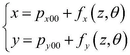
S3:提取γ为0时的序列{x,y,z,θ,γ=0},采用数据拟合的方法分别建立x、y与z和θ之间的关系:S3: Extract the sequence {x, y, z, θ, γ=0} when γ is 0, and use the method of data fitting to establish the relationship between x, y, z and θ respectively:

其中,px00和py00为常量,fx和fy为相应的拟合函数;Among them, p x00 and p y00 are constants, f x and f y are corresponding fitting functions;
S4:对相同z和θ、不同γ的序列中的{x,y}进行圆拟合,得到序列{z,θ,xc,yc,r},其中,xc和yc为拟合的圆心所对应的x和y值,r为拟合的圆半径;S4: Perform circle fitting on {x, y} in the sequence of the same z and θ, different γ, and obtain the sequence {z, θ, x c , y c , r}, where x c and y c are fitting The x and y values corresponding to the center of the circle, r is the radius of the fitted circle;
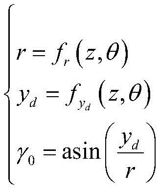
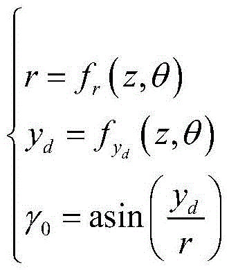
S5:采用数据拟合的方法建立r、γ0与z和θ之间的关系:S5: Use the method of data fitting to establish the relationship between r, γ 0 and z and θ:

其中,γ0为拟合圆的初始角度,yd为γ=0时y相对于yc的偏移量,fr和fyd为相应的拟合函数;Among them, γ 0 is the initial angle of the fitting circle, y d is the offset of y relative to y c when γ = 0, f r and f yd are the corresponding fitting functions;
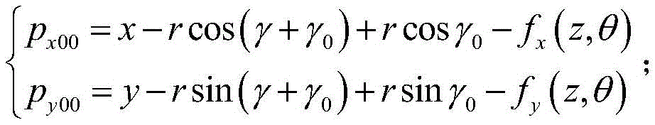
S6:使用拟合的函数对伺服系统误差进行补偿,若载物台水平移动,动态修正px00和py00:S6: Use the fitted function to compensate the error of the servo system. If the stage moves horizontally, dynamically correct p x00 and p y00 :
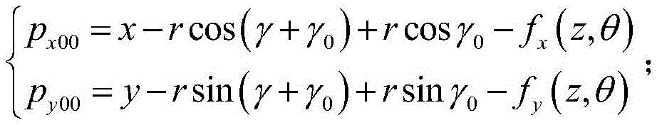
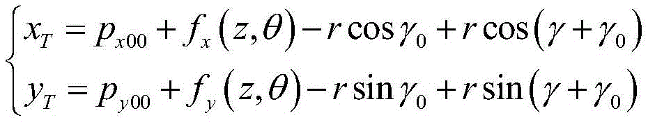
若载物台高度z、探测器倾斜角度θ、探测器旋转角度γ发生变化,则:If the stage height z, detector tilt angle θ, and detector rotation angle γ change, then:
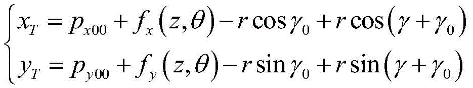
其中,xT、yT为载物台高度z、探测器倾斜角度θ、探测器旋转角度γ发生变化后的随动位置。Among them, x T , y T are the follow-up positions after the height z of the stage, the tilt angle θ of the detector, and the rotation angle γ of the detector change.
更进一步地,在所述步骤S1中,所述具有已知几何形状的基准标记为金属球。Furthermore, in the step S1, the reference mark with a known geometric shape is a metal ball.
更进一步地,在所述步骤S2中,所述基准标记的特征为几何中心、质心、最小外接圆心。Furthermore, in the step S2, the features of the reference mark are the geometric center, the centroid, and the center of the smallest circumscribed circle.
更进一步地,在所述步骤S3、S5中,数据拟合方法为多项式拟合、神经网络拟合等方式。Furthermore, in the steps S3 and S5, the data fitting methods are polynomial fitting, neural network fitting and the like.
本发明相比现有技术具有以下优点:该伺服系统误差补偿方法,适用于基于五轴运动平台的X射线检测装置,以金属微球作为标记物,采用X光对标记物进行成像,以所成像的圆心在视野的位置不变作为约束条件,统计载物台水平位置、载物台高度、探测器倾斜角度和旋转角度,采用多项式拟合的方法建立五轴运动关系,根据运动关系,载物台水平位置跟随载物台高度、探测器倾斜角度和旋转角度变化,实现不同放大比、不同视角下始终保持视野中心不变,对所关注区域进行成像;可建立点物像在空间的绝对位置关系,不仅能满足不同放大比、不同视角下始终保持视野中心不变的需求,还可应用于平面CT成像中,不需要额外的平面CT模块,即可实现被测物体的三维成像;采用软件的方法对伺服系统误差进行补偿,不需要额外的高精度机械设备和检测设备,性价比高,值得被推广使用。Compared with the prior art, the present invention has the following advantages: the servo system error compensation method is suitable for an X-ray detection device based on a five-axis motion platform, uses metal microspheres as markers, and uses X-rays to image the markers, so that The position of the center of the imaging circle in the field of view remains unchanged as a constraint condition, and the horizontal position of the stage, the height of the stage, the tilt angle and the rotation angle of the detector are counted, and the five-axis motion relationship is established by using a polynomial fitting method. According to the motion relationship, the load The horizontal position of the object stage changes with the height of the stage, the inclination angle and the rotation angle of the detector, so that the center of the field of view is always kept constant under different magnification ratios and different viewing angles, and the area of interest is imaged; the absolute position of the point image in space can be established. The positional relationship can not only meet the requirement of keeping the center of the field of view constant under different magnification ratios and different viewing angles, but also can be applied to planar CT imaging, and can realize three-dimensional imaging of the measured object without additional planar CT modules; The software method compensates the error of the servo system, does not require additional high-precision mechanical equipment and testing equipment, is cost-effective, and is worthy of promotion and use.
附图说明Description of drawings
图1是本发明实施例二中伺服系统误差补偿方法的数据采集和拟合流程图;Fig. 1 is the flow chart of data acquisition and fitting of the servo system error compensation method in the second embodiment of the present invention;
图2是本发明实施例二中伺服系统误差补偿方法的误差补偿流程图;Fig. 2 is the error compensation flowchart of the servo system error compensation method in the second embodiment of the present invention;
图3a是本发明实施例二中fx(z,θ)数据拟合结果示意图;Fig. 3 a is a schematic diagram of f x (z, θ) data fitting results in Example 2 of the present invention;
图3b是图3a中的数据拟合残差示意图;Fig. 3b is a schematic diagram of the data fitting residual in Fig. 3a;
图4A是本发明实施例二中fy(z,θ)数据拟合结果示意图;Fig. 4A is a schematic diagram of the data fitting results of f y (z, θ) in Example 2 of the present invention;
图4a是图4A中的数据拟合残差示意图;Figure 4a is a schematic diagram of the data fitting residuals in Figure 4A;
图4B是本发明实施例二中fr(z,θ)数据拟合结果示意图;Fig. 4B is a schematic diagram of the data fitting results of f r (z, θ) in Example 2 of the present invention;
图4b是图4B中的数据拟合残差示意图;Fig. 4b is a schematic diagram of the data fitting residual in Fig. 4B;
图4C是本发明实施例二中fyd(z,θ)数据拟合结果示意图;Fig. 4C is a schematic diagram of the data fitting results of f yd (z, θ) in Example 2 of the present invention;
图4c是图4C中的数据拟合残差示意图。Figure 4c is a schematic diagram of the data fitting residuals in Figure 4C.
具体实施方式Detailed ways
下面对本发明的实施例作详细说明,本实施例在以本发明技术方案为前提下进行实施,给出了详细的实施方式和具体的操作过程,但本发明的保护范围不限于下述的实施例。The embodiments of the present invention are described in detail below. This embodiment is implemented on the premise of the technical solution of the present invention, and detailed implementation methods and specific operating procedures are provided, but the protection scope of the present invention is not limited to the following implementation example.
实施例一Embodiment one
本实施例提供一种技术方案:一种伺服系统误差补偿方法,包括以下步骤:This embodiment provides a technical solution: a servo system error compensation method, including the following steps:
S1:利用X光识别载物台表面上的具有已知几何形状的基准标记,实时获取图像,图像中包含基准标记;S1: Use X-rays to identify fiducial marks with known geometric shapes on the surface of the stage, and acquire images in real time, which contain fiducial marks;
S2:移动载物台高度z、探测器倾斜角度θ、探测器旋转角度γ,通过调整载物台水平位置x和y,使基准标记的特征在图像中的位置保持不变,得到序列{x,y,z,θ,γ};S2: Move the stage height z, the detector tilt angle θ, and the detector rotation angle γ. By adjusting the horizontal position x and y of the stage, the position of the feature of the fiducial mark in the image remains unchanged, and the sequence {x ,y,z,θ,γ};
S3:提取γ为0时的序列{x,y,z,θ,γ=0},采用数据拟合的方法分别建立x、y与z和θ之间的关系:S3: Extract the sequence {x, y, z, θ, γ=0} when γ is 0, and use the method of data fitting to establish the relationship between x, y, z and θ respectively:
其中,px00和py00为常量,fx和fy为相应的拟合函数;Among them, p x00 and p y00 are constants, f x and f y are corresponding fitting functions;
S4:对相同z和θ、不同γ的序列中的{x,y}进行圆拟合,得到序列{z,θ,xc,yc,r},其中,xc和yc为拟合的圆心所对应的x和y值,r为拟合的圆半径;S4: Perform circle fitting on {x, y} in the sequence of the same z and θ, different γ, and obtain the sequence {z, θ, x c , y c , r}, where x c and y c are fitting The x and y values corresponding to the center of the circle, r is the radius of the fitted circle;
S5:采用数据拟合的方法建立r、γ0与z和θ之间的关系:S5: Use the method of data fitting to establish the relationship between r, γ 0 and z and θ:
其中,γ0为拟合圆的初始角度,yd为γ=0时y相对于yc的偏移量,fr和fyd为相应的拟合函数;Among them, γ 0 is the initial angle of the fitting circle, y d is the offset of y relative to y c when γ = 0, f r and f yd are the corresponding fitting functions;
S6:使用拟合的函数对伺服系统误差进行补偿,若载物台水平移动,动态修正px00和py00:S6: Use the fitted function to compensate the error of the servo system. If the stage moves horizontally, dynamically correct p x00 and p y00 :
若载物台高度z、探测器倾斜角度θ、探测器旋转角度γ发生变化,则If the stage height z, the detector tilt angle θ, and the detector rotation angle γ change, then
其中,xT、yT为载物台高度z、探测器倾斜角度θ、探测器旋转角度γ发生变化后随动位置。Among them, x T , y T are the follow-up positions after changes in the height z of the stage, the tilt angle θ of the detector, and the rotation angle γ of the detector.
在本实施例中,在所述步骤S3、S5中,数据拟合方法为多项式拟合、神经网络拟合等方式。In this embodiment, in the steps S3 and S5, the data fitting methods are polynomial fitting, neural network fitting and the like.
在本实施例中,在所述步骤S1中,所述具有已知几何形状的基准标记为金属球。In this embodiment, in the step S1, the reference mark with a known geometric shape is a metal ball.
在本实施例中,在所述步骤S2中,所述基准标记的特征为最小外接圆心。In this embodiment, in the step S2, the feature of the reference mark is the center of the smallest circumscribed circle.
在本实施例中,在伺服系统的控制下,所述载物台可在水平方向进行两轴(x轴与y轴,两轴相互垂直)移动,并可在竖直方向(z轴)进行移动。In this embodiment, under the control of the servo system, the stage can move in two axes (x-axis and y-axis, the two axes are perpendicular to each other) in the horizontal direction, and can move in the vertical direction (z-axis). move.
实施例二Embodiment two
根据图1所示的方法进行数据采集和处理,载物台高度z变化范围为20~50mm、探测器倾斜角度θ范围为0~45°、探测器旋转角度γ范围为-180°~180°,采用多项式拟合方法和圆拟合的方法对采样数据进行处理,得到fx、fy、fr和fyd函数,其拟合情况如图3a、图4A、图4B、图4C所示,拟合残差如图3b、图4a、图4b和图4c所示,残差小于50μm,说明该方法的有效性。According to the method shown in Figure 1 for data acquisition and processing, the height z of the stage varies from 20 to 50 mm, the tilt angle θ of the detector ranges from 0 to 45°, and the rotation angle γ of the detector ranges from -180° to 180° , using the polynomial fitting method and the circle fitting method to process the sampled data to obtain f x , f y , f r and f yd functions, and the fitting conditions are shown in Fig. 3a, Fig. 4A, Fig. 4B, and Fig. 4C , the fitting residuals are shown in Figure 3b, Figure 4a, Figure 4b and Figure 4c, and the residual error is less than 50 μm, which shows the effectiveness of the method.
综上所述,上述实施例的伺服系统误差补偿方法,适用于基于五轴运动平台的X射线检测装置,以金属微球作为标记物,采用X光对标记物进行成像,以所成像的圆心在视野的位置不变作为约束条件,统计载物台水平位置、载物台高度、探测器倾斜角度和旋转角度,采用多项式拟合的方法建立五轴运动关系,根据运动关系,载物台水平位置跟随载物台高度、探测器倾斜角度和旋转角度变化,实现不同放大比、不同视角下始终保持视野中心不变,对所关注区域进行成像;可建立点物像在空间的绝对位置关系,不仅能满足不同放大比、不同视角下始终保持视野中心不变的需求,还可应用于平面CT成像中,不需要额外的平面CT模块,即可实现被测物体的三维成像;采用软件的方法对伺服系统误差进行补偿,不需要额外的高精度机械设备和检测设备,性价比高,值得被推广使用。In summary, the servo system error compensation method of the above-mentioned embodiment is applicable to an X-ray detection device based on a five-axis motion platform, using metal microspheres as markers, imaging the markers with X-rays, and using the imaged circle center When the position of the field of view remains unchanged as a constraint condition, the horizontal position of the stage, the height of the stage, the tilt angle and the rotation angle of the detector are counted, and the polynomial fitting method is used to establish the five-axis motion relationship. According to the motion relationship, the level of the stage The position follows the height of the stage, the tilt angle and rotation angle of the detector, and realizes that the center of the field of view remains unchanged under different magnification ratios and different viewing angles, and the area of interest is imaged; the absolute position relationship of the point image in space can be established, Not only can it meet the requirement of keeping the center of field of view constant under different magnification ratios and different viewing angles, but it can also be used in planar CT imaging, and it can realize three-dimensional imaging of the measured object without additional planar CT modules; using software methods Compensating the error of the servo system does not require additional high-precision mechanical equipment and testing equipment. It is cost-effective and worthy of promotion and use.
尽管上面已经示出和描述了本发明的实施例,可以理解的是,上述实施例是示例性的,不能理解为对本发明的限制,本领域的普通技术人员在本发明的范围内可以对上述实施例进行变化、修改、替换和变型。Although the embodiments of the present invention have been shown and described above, it can be understood that the above embodiments are exemplary and should not be construed as limiting the present invention, those skilled in the art can make the above-mentioned The embodiments are subject to changes, modifications, substitutions and variations.
Claims (3)


Priority Applications (1)
| Application Number | Priority Date | Filing Date | Title |
|---|---|---|---|
| CN202210220140.4A CN114460110B (en) | 2022-03-08 | 2022-03-08 | Servo system error compensation method |
Applications Claiming Priority (1)
| Application Number | Priority Date | Filing Date | Title |
|---|---|---|---|
| CN202210220140.4A CN114460110B (en) | 2022-03-08 | 2022-03-08 | Servo system error compensation method |
Publications (2)
| Publication Number | Publication Date |
|---|---|
| CN114460110A CN114460110A (en) | 2022-05-10 |
| CN114460110B true CN114460110B (en) | 2023-06-06 |
Family
ID=81416582
Family Applications (1)
| Application Number | Title | Priority Date | Filing Date |
|---|---|---|---|
| CN202210220140.4A Active CN114460110B (en) | 2022-03-08 | 2022-03-08 | Servo system error compensation method |
Country Status (1)
| Country | Link |
|---|---|
| CN (1) | CN114460110B (en) |
Citations (2)
| Publication number | Priority date | Publication date | Assignee | Title |
|---|---|---|---|---|
| EP2645701A1 (en) * | 2012-03-29 | 2013-10-02 | Axis AB | Method for calibrating a camera |
| CN108122203A (en) * | 2016-11-29 | 2018-06-05 | 上海东软医疗科技有限公司 | A kind of bearing calibration of geometric parameter, device, equipment and system |
Family Cites Families (19)
| Publication number | Priority date | Publication date | Assignee | Title |
|---|---|---|---|---|
| US6493646B1 (en) * | 2000-02-16 | 2002-12-10 | Ge Medical Systems Global Technology Company, Llc | High order primary decay correction for CT imaging system detectors |
| JP4041637B2 (en) * | 2000-03-31 | 2008-01-30 | 東芝Itコントロールシステム株式会社 | X-ray fluoroscopy system |
| JP3802869B2 (en) * | 2002-12-02 | 2006-07-26 | ジーイー・メディカル・システムズ・グローバル・テクノロジー・カンパニー・エルエルシー | Beam hardening post-processing method and X-ray CT apparatus |
| US6848827B2 (en) * | 2003-05-13 | 2005-02-01 | General Electric Company | Method and apparatus for calibrating detector spectral response |
| DE102005033187A1 (en) * | 2005-07-13 | 2007-01-25 | Carl Zeiss Industrielle Messtechnik Gmbh | Measuring arrangement e.g. computed tomography measuring arrangement, calibrating method, involves determining geometry parameter of geometrical model, which describes geometry of arrangement, by evaluation of radiographic image |
| US7581884B1 (en) * | 2006-02-07 | 2009-09-01 | Barnes Gary T | Mobile radiography system and grid alignment process |
| US7780672B2 (en) * | 2006-02-27 | 2010-08-24 | Biomet Manufacturing Corp. | Femoral adjustment device and associated method |
| TWI623825B (en) * | 2006-09-01 | 2018-05-11 | Nikon Corporation | Exposure device and method, and element manufacturing method |
| EP2326250B1 (en) * | 2008-08-13 | 2017-01-11 | Koninklijke Philips N.V. | Calibration method for ring artifact correction in non-ideal isocentric 3d rotational x-ray scanner systems using a calibration phantom based rotation center finding algorithm |
| JP2012042340A (en) * | 2010-08-19 | 2012-03-01 | Shimadzu Corp | X-ray ct equipment |
| DE102013205406A1 (en) * | 2013-03-27 | 2014-10-16 | Siemens Aktiengesellschaft | X-ray imaging system for X-ray imaging at high image frequencies of an examination subject by direct measurement of the interference pattern |
| GB2520711B (en) * | 2013-11-28 | 2018-06-20 | Nikon Metrology Nv | Calibration apparatus and method for computed tomography |
| CN103784160B (en) * | 2014-03-06 | 2015-12-23 | 北京锐视康科技发展有限公司 | A kind of correcting unit of cone-beam CT system geometric position and bearing calibration thereof |
| CN104764756B (en) * | 2015-03-30 | 2017-05-31 | 清华大学 | The scaling method of cone-beam CT imaging system |
| CN105769233A (en) * | 2016-02-29 | 2016-07-20 | 江苏美伦影像系统有限公司 | Geometric correction method |
| CN110220926B (en) * | 2019-07-03 | 2020-03-27 | 中国电子科技集团公司第三十八研究所 | An X-ray detection device based on a five-axis motion platform |
| CN111678472B (en) * | 2020-06-09 | 2022-02-15 | 无锡身为度信息技术有限公司 | Error identification method for rotary table of four-axis coordinate measuring machine |
| JP2022010983A (en) * | 2020-06-29 | 2022-01-17 | 株式会社ミツトヨ | Method for calibrating x-ray measuring device |
| CN113902645B (en) * | 2021-10-27 | 2022-12-16 | 中国电子科技集团公司第三十八研究所 | A Method for Acquiring RPC Correction Parameters of Spaceborne SAR Images Based on Inverse RD Positioning Model |
-
2022
- 2022-03-08 CN CN202210220140.4A patent/CN114460110B/en active Active
Patent Citations (2)
| Publication number | Priority date | Publication date | Assignee | Title |
|---|---|---|---|---|
| EP2645701A1 (en) * | 2012-03-29 | 2013-10-02 | Axis AB | Method for calibrating a camera |
| CN108122203A (en) * | 2016-11-29 | 2018-06-05 | 上海东软医疗科技有限公司 | A kind of bearing calibration of geometric parameter, device, equipment and system |
Also Published As
| Publication number | Publication date |
|---|---|
| CN114460110A (en) | 2022-05-10 |
Similar Documents
| Publication | Publication Date | Title |
|---|---|---|
| US9442080B2 (en) | Method and apparatus for generating a three-dimensional model of a region of interest using an imaging system | |
| CN114695225A (en) | Wafer pre-alignment device and wafer pre-alignment method | |
| US11402524B2 (en) | Geometric calibration of X-ray imaging systems | |
| JP6131606B2 (en) | Radiation imaging apparatus and image processing method therefor | |
| CN110960234A (en) | Systems and methods for calibrating imaging systems | |
| US20060106497A1 (en) | Carriage robot system and its controlling method | |
| CN112556611A (en) | Calibration method for X-ray measuring device | |
| JP4969279B2 (en) | Position detection method and position detection apparatus | |
| CN114485389B (en) | Distortion aberration correction processing device, distortion aberration correction method and storage medium | |
| CN113932741A (en) | Calibration method for an X-ray measuring device | |
| CN114460110B (en) | Servo system error compensation method | |
| CN112461165A (en) | Calibration method for X-ray measuring device | |
| CN114544676B (en) | Data acquisition method for high-precision error compensation of servo system | |
| CN115597559A (en) | A method of leveling the turntable based on optical imaging | |
| CN115836875A (en) | Calibration method and system | |
| CN116295008A (en) | Device and method for detecting repetitive motion accuracy of a reciprocating mechanism | |
| CN120468184A (en) | Planar CT geometric calibration method, system, storage medium and device | |
| CN120279110A (en) | Automatic calibration method and system for camera | |
| CN118781185A (en) | A method and optical system for realizing center alignment of surface shape absolute detection based on visual image sub-pixel positioning | |
| EP4346607B1 (en) | Calibration phantom, method and system | |
| CN111458739B (en) | Imaging method, device and system | |
| JPH1080882A (en) | Measurement method of coordinate conversion parameters for robot | |
| CN108364325A (en) | Regular sample X ray CT perspective view position translation separate-blas estimation and bearing calibration | |
| CN114372963A (en) | Method for generating PCB reference point by using available arc | |
| JP2001227915A (en) | Method for detecting displacement of camera, method for detecting inclination of camera, and method for correcting amount of movement of camera for image pickup apparatus |
Legal Events
| Date | Code | Title | Description |
|---|---|---|---|
| PB01 | Publication | ||
| PB01 | Publication | ||
| SE01 | Entry into force of request for substantive examination | ||
| SE01 | Entry into force of request for substantive examination | ||
| GR01 | Patent grant | ||
| GR01 | Patent grant |