CN114452527B - Device for assisting heart in the event of failure - Google Patents
Device for assisting heart in the event of failure Download PDFInfo
- Publication number
- CN114452527B CN114452527B CN202210093108.4A CN202210093108A CN114452527B CN 114452527 B CN114452527 B CN 114452527B CN 202210093108 A CN202210093108 A CN 202210093108A CN 114452527 B CN114452527 B CN 114452527B
- Authority
- CN
- China
- Prior art keywords
- motor
- magnetic
- rotor shaft
- pump
- magnetic force
- Prior art date
- Legal status (The legal status is an assumption and is not a legal conclusion. Google has not performed a legal analysis and makes no representation as to the accuracy of the status listed.)
- Active
Links
Images


Classifications
-
- A—HUMAN NECESSITIES
- A61—MEDICAL OR VETERINARY SCIENCE; HYGIENE
- A61M—DEVICES FOR INTRODUCING MEDIA INTO, OR ONTO, THE BODY; DEVICES FOR TRANSDUCING BODY MEDIA OR FOR TAKING MEDIA FROM THE BODY; DEVICES FOR PRODUCING OR ENDING SLEEP OR STUPOR
- A61M60/00—Blood pumps; Devices for mechanical circulatory actuation; Balloon pumps for circulatory assistance
- A61M60/10—Location thereof with respect to the patient's body
- A61M60/122—Implantable pumps or pumping devices, i.e. the blood being pumped inside the patient's body
- A61M60/126—Implantable pumps or pumping devices, i.e. the blood being pumped inside the patient's body implantable via, into, inside, in line, branching on, or around a blood vessel
- A61M60/13—Implantable pumps or pumping devices, i.e. the blood being pumped inside the patient's body implantable via, into, inside, in line, branching on, or around a blood vessel by means of a catheter allowing explantation, e.g. catheter pumps temporarily introduced via the vascular system
-
- A—HUMAN NECESSITIES
- A61—MEDICAL OR VETERINARY SCIENCE; HYGIENE
- A61M—DEVICES FOR INTRODUCING MEDIA INTO, OR ONTO, THE BODY; DEVICES FOR TRANSDUCING BODY MEDIA OR FOR TAKING MEDIA FROM THE BODY; DEVICES FOR PRODUCING OR ENDING SLEEP OR STUPOR
- A61M60/00—Blood pumps; Devices for mechanical circulatory actuation; Balloon pumps for circulatory assistance
- A61M60/10—Location thereof with respect to the patient's body
- A61M60/122—Implantable pumps or pumping devices, i.e. the blood being pumped inside the patient's body
- A61M60/126—Implantable pumps or pumping devices, i.e. the blood being pumped inside the patient's body implantable via, into, inside, in line, branching on, or around a blood vessel
- A61M60/135—Implantable pumps or pumping devices, i.e. the blood being pumped inside the patient's body implantable via, into, inside, in line, branching on, or around a blood vessel inside a blood vessel, e.g. using grafting
-
- A—HUMAN NECESSITIES
- A61—MEDICAL OR VETERINARY SCIENCE; HYGIENE
- A61M—DEVICES FOR INTRODUCING MEDIA INTO, OR ONTO, THE BODY; DEVICES FOR TRANSDUCING BODY MEDIA OR FOR TAKING MEDIA FROM THE BODY; DEVICES FOR PRODUCING OR ENDING SLEEP OR STUPOR
- A61M60/00—Blood pumps; Devices for mechanical circulatory actuation; Balloon pumps for circulatory assistance
- A61M60/10—Location thereof with respect to the patient's body
- A61M60/122—Implantable pumps or pumping devices, i.e. the blood being pumped inside the patient's body
- A61M60/165—Implantable pumps or pumping devices, i.e. the blood being pumped inside the patient's body implantable in, on, or around the heart
- A61M60/178—Implantable pumps or pumping devices, i.e. the blood being pumped inside the patient's body implantable in, on, or around the heart drawing blood from a ventricle and returning the blood to the arterial system via a cannula external to the ventricle, e.g. left or right ventricular assist devices
-
- A—HUMAN NECESSITIES
- A61—MEDICAL OR VETERINARY SCIENCE; HYGIENE
- A61M—DEVICES FOR INTRODUCING MEDIA INTO, OR ONTO, THE BODY; DEVICES FOR TRANSDUCING BODY MEDIA OR FOR TAKING MEDIA FROM THE BODY; DEVICES FOR PRODUCING OR ENDING SLEEP OR STUPOR
- A61M60/00—Blood pumps; Devices for mechanical circulatory actuation; Balloon pumps for circulatory assistance
- A61M60/20—Type thereof
- A61M60/205—Non-positive displacement blood pumps
- A61M60/216—Non-positive displacement blood pumps including a rotating member acting on the blood, e.g. impeller
-
- A—HUMAN NECESSITIES
- A61—MEDICAL OR VETERINARY SCIENCE; HYGIENE
- A61M—DEVICES FOR INTRODUCING MEDIA INTO, OR ONTO, THE BODY; DEVICES FOR TRANSDUCING BODY MEDIA OR FOR TAKING MEDIA FROM THE BODY; DEVICES FOR PRODUCING OR ENDING SLEEP OR STUPOR
- A61M60/00—Blood pumps; Devices for mechanical circulatory actuation; Balloon pumps for circulatory assistance
- A61M60/40—Details relating to driving
- A61M60/403—Details relating to driving for non-positive displacement blood pumps
- A61M60/408—Details relating to driving for non-positive displacement blood pumps the force acting on the blood contacting member being mechanical, e.g. transmitted by a shaft or cable
- A61M60/411—Details relating to driving for non-positive displacement blood pumps the force acting on the blood contacting member being mechanical, e.g. transmitted by a shaft or cable generated by an electromotor
- A61M60/414—Details relating to driving for non-positive displacement blood pumps the force acting on the blood contacting member being mechanical, e.g. transmitted by a shaft or cable generated by an electromotor transmitted by a rotating cable, e.g. for blood pumps mounted on a catheter
-
- A—HUMAN NECESSITIES
- A61—MEDICAL OR VETERINARY SCIENCE; HYGIENE
- A61M—DEVICES FOR INTRODUCING MEDIA INTO, OR ONTO, THE BODY; DEVICES FOR TRANSDUCING BODY MEDIA OR FOR TAKING MEDIA FROM THE BODY; DEVICES FOR PRODUCING OR ENDING SLEEP OR STUPOR
- A61M60/00—Blood pumps; Devices for mechanical circulatory actuation; Balloon pumps for circulatory assistance
- A61M60/40—Details relating to driving
- A61M60/403—Details relating to driving for non-positive displacement blood pumps
- A61M60/419—Details relating to driving for non-positive displacement blood pumps the force acting on the blood contacting member being permanent magnetic, e.g. from a rotating magnetic coupling between driving and driven magnets
-
- A—HUMAN NECESSITIES
- A61—MEDICAL OR VETERINARY SCIENCE; HYGIENE
- A61M—DEVICES FOR INTRODUCING MEDIA INTO, OR ONTO, THE BODY; DEVICES FOR TRANSDUCING BODY MEDIA OR FOR TAKING MEDIA FROM THE BODY; DEVICES FOR PRODUCING OR ENDING SLEEP OR STUPOR
- A61M60/00—Blood pumps; Devices for mechanical circulatory actuation; Balloon pumps for circulatory assistance
- A61M60/80—Constructional details other than related to driving
- A61M60/802—Constructional details other than related to driving of non-positive displacement blood pumps
- A61M60/818—Bearings
-
- A—HUMAN NECESSITIES
- A61—MEDICAL OR VETERINARY SCIENCE; HYGIENE
- A61M—DEVICES FOR INTRODUCING MEDIA INTO, OR ONTO, THE BODY; DEVICES FOR TRANSDUCING BODY MEDIA OR FOR TAKING MEDIA FROM THE BODY; DEVICES FOR PRODUCING OR ENDING SLEEP OR STUPOR
- A61M60/00—Blood pumps; Devices for mechanical circulatory actuation; Balloon pumps for circulatory assistance
- A61M60/80—Constructional details other than related to driving
- A61M60/855—Constructional details other than related to driving of implantable pumps or pumping devices
- A61M60/857—Implantable blood tubes
- A61M60/859—Connections therefor
-
- A—HUMAN NECESSITIES
- A61—MEDICAL OR VETERINARY SCIENCE; HYGIENE
- A61M—DEVICES FOR INTRODUCING MEDIA INTO, OR ONTO, THE BODY; DEVICES FOR TRANSDUCING BODY MEDIA OR FOR TAKING MEDIA FROM THE BODY; DEVICES FOR PRODUCING OR ENDING SLEEP OR STUPOR
- A61M60/00—Blood pumps; Devices for mechanical circulatory actuation; Balloon pumps for circulatory assistance
- A61M60/90—Details not provided for in groups A61M60/40, A61M60/50 or A61M60/80
Landscapes
- Health & Medical Sciences (AREA)
- Heart & Thoracic Surgery (AREA)
- Engineering & Computer Science (AREA)
- Cardiology (AREA)
- Life Sciences & Earth Sciences (AREA)
- Anesthesiology (AREA)
- Biomedical Technology (AREA)
- Hematology (AREA)
- Mechanical Engineering (AREA)
- Animal Behavior & Ethology (AREA)
- General Health & Medical Sciences (AREA)
- Public Health (AREA)
- Veterinary Medicine (AREA)
- Vascular Medicine (AREA)
- Transplantation (AREA)
- External Artificial Organs (AREA)
Abstract
提供一种用于对心脏在发生功能衰竭时进行辅助的装置,包括马达、与马达可拆卸接合的耦合器、驱动转子、设在耦合器中的从动转子、近端连接至耦合器的导管、穿设在导管中并由转子轴驱动的驱动轴,以及被驱动轴驱动进行泵血的泵。驱动转子包括连接至马达输出轴的第一支架、设在第一支架上的驱动件;从动转子包括转子轴、设在转子轴上并与驱动件耦合的从动件。驱动件和从动件中的一个为磁力提供元件,另一个为导体,两者之间形成间隙。
Provided is a device for assisting the heart in the event of functional failure, comprising a motor, a coupler detachably engaged with the motor, a driving rotor, a driven rotor disposed in the coupler, a catheter proximally connected to the coupler , a drive shaft passing through the catheter and driven by the rotor shaft, and a pump driven by the drive shaft to pump blood. The driving rotor includes a first bracket connected to the output shaft of the motor, and a driving element arranged on the first bracket; the driven rotor includes a rotor shaft, a driven element arranged on the rotor shaft and coupled with the driving element. One of the driving member and the driven member is a magnetic force providing element, and the other is a conductor, forming a gap therebetween.
Description
【技术领域】【Technical field】
本发明涉及一种用于对心脏在发生功能衰竭时进行辅助的装置,属于医疗器械技术领域。The invention relates to a device for assisting the heart when its function fails, and belongs to the technical field of medical devices.
【背景技术】【Background technique】
心力衰竭是一种致死率很高的健康问题。以心源性休克为例,患者左心室的喷射性能显著减弱,减弱的冠状动脉供血可能导致不可逆的心脏衰退。因此,针对这种病例,临时的介入支持(心室辅助),会局部或大部分地替代左心室的泵血功能,并且提高冠状动脉供血。Heart failure is a health problem with a high mortality rate. Taking cardiogenic shock as an example, the ejection performance of the left ventricle of the patient is significantly weakened, and the weakened coronary blood supply may lead to irreversible heart failure. Therefore, for this case, temporary interventional support (ventricular assist) will partially or mostly replace the pumping function of the left ventricle and improve coronary blood supply.
现有的心室辅助装置,出于液体密封(防止灌注液进入马达)的要求,采用磁耦合的方式将马达的动力传递给驱动轴,是比较常见的手段。具体为:马达的输出轴上设置的主动磁体和连接至驱动轴近端的被动磁体耦合,马达带动主动磁体旋转时,在主、被动磁体的磁力耦合的作用下,驱动轴被驱动旋转,进而带动叶轮旋转,实现泵血。In existing ventricular assist devices, due to the requirement of liquid sealing (preventing the perfusate from entering the motor), it is relatively common to use magnetic coupling to transmit the power of the motor to the drive shaft. Specifically: the active magnet provided on the output shaft of the motor is coupled with the passive magnet connected to the proximal end of the drive shaft. When the motor drives the active magnet to rotate, the drive shaft is driven to rotate under the action of the magnetic force coupling between the active and passive magnets, and then Drive the impeller to rotate to achieve blood pumping.
如CN103120810B记载,磁耦合具有离合器的作用。在磁耦合可传递的扭矩超过设定扭矩时,例如前端的叶轮转动受阻,则两个磁体分开。此时,马达即便正常旋转,但驱动轴和叶轮处于或基本处于停转的状态,泵失效而无法继续泵血。As described in CN103120810B, the magnetic coupling has the effect of a clutch. When the transmissible torque of the magnetic coupling exceeds the set torque, for example, the rotation of the impeller at the front end is blocked, and the two magnets are separated. At this time, even though the motor rotates normally, the drive shaft and the impeller are in or basically in a stalled state, and the pump fails and cannot continue to pump blood.
值得注意的是,磁耦合具有的转动受阻而断开动力传递的特性,旨在保护心室组织不被破坏。但同时,这会引发一系列不良的后果,包括:It is worth noting that the magnetic coupling has the property of blocking the rotation and disconnecting the power transmission, which is designed to protect the ventricular tissue from being damaged. But at the same time, this can lead to a series of undesirable consequences, including:
1、在泵失去泵血功能的情况下,加上介入心室辅助装置的受试者(例如,人)本身心脏泵血能力不足,必然会导致血液流动不畅甚至不流动,则心室辅助装置介入至受试者体内的部分包括导管及泵组件上容易形成血栓。而血栓的危害是显而易见的,包括但不限于:血栓随血流在全身流动后进入大脑而引发中风、血栓不流动而滞留在血管某处引发附近神经组织供氧不良而发生神经损伤。1. In the case that the pump loses its function of pumping blood, and the subject (for example, a person) who is involved in the ventricular assist device has insufficient heart pumping ability, it will inevitably lead to poor or even no flow of blood, and the intervention of the ventricular assist device Parts of the subject's body, including the catheter and pump components, are prone to thrombus formation. The hazards of thrombus are obvious, including but not limited to: thrombus enters the brain with the blood flow through the whole body and causes stroke, and thrombus does not flow but stays somewhere in the blood vessel, causing poor oxygen supply to nearby nerve tissue and nerve damage.
2、基于磁耦合的原理,转动受阻而使叶轮大幅降速之后,难以甚至无法在阻力消失后实现彻底的复转。实际而言,在心室辅助这一高转速场景中,叶轮降速后欲意复转,只能通过停机的方式来实现。这对临床需要给受试者提供持续的心室辅助作用,显然是不利的。2. Based on the principle of magnetic coupling, after the rotation is blocked and the impeller slows down significantly, it is difficult or even impossible to achieve a complete rerotation after the resistance disappears. Practically speaking, in the high-speed scenario of ventricular assist, if the impeller wants to turn back after the speed is reduced, it can only be realized by stopping the impeller. This is obviously unfavorable for the clinical need to provide continuous ventricular assistance to the subjects.
进一步地,在不借助其他自动化的侦测手段来反馈由于叶轮大幅降速而导致血流量下降的情况下,一般只能由人为通过观察和经验来判断。并且,即便在阻力消失后,也需要人为干预实现复转。这对心室辅助这一高危运用场景所通常面临的紧张的医护资源以及复杂的临床环境而言,也是不现实的。Further, without using other automatic detection means to feedback the decrease in blood flow due to the large speed reduction of the impeller, generally it can only be judged manually through observation and experience. Moreover, even after the resistance disappears, human intervention is required to achieve recovery. This is also unrealistic for the tense medical resources and complex clinical environment usually faced by the high-risk application scenario of ventricular assistance.
【发明内容】【Content of invention】
本发明的目的在于提供一种用于对心脏在发生功能衰竭时进行辅助的装置,可至少解决上述问题之一。The purpose of the present invention is to provide a device for assisting the heart in failure, which can solve at least one of the above problems.
本发明的目的是通过以下技术方案实现:The purpose of the present invention is to realize through the following technical solutions:
一种用于对心脏在发生功能衰竭时进行辅助的装置,包括:马达、与马达可拆卸接合的耦合器、驱动转子、设在耦合器中的从动转子、近端连接至耦合器的导管、穿设在导管中并由转子轴驱动的驱动轴、以及被驱动轴驱动进行泵血的泵。其中,泵包括:连接至导管远端并具有进口端和出口端的泵壳、收纳在泵壳内的叶轮。叶轮被驱动轴驱动旋转以将血液从进口端吸入泵壳并从出口端排出。驱动转子包括:连接至马达输出轴的第一支架、设在第一支架上的驱动件。从动转子包括:转子轴、设在转子轴上并与驱动件耦合的从动件。驱动件和从动件中的一个为磁力提供元件,另一个为导体,两者之间形成间隙。A device for assisting the heart in the event of functional failure, comprising: a motor, a coupler detachably engaged with the motor, a driving rotor, a driven rotor disposed in the coupler, a catheter proximally connected to the coupler , a drive shaft passed through the catheter and driven by the rotor shaft, and a pump driven by the drive shaft to pump blood. Wherein, the pump includes: a pump casing connected to the distal end of the conduit and having an inlet end and an outlet end, and an impeller accommodated in the pump casing. The impeller is driven in rotation by the drive shaft to draw blood into the pump casing from the inlet end and out through the outlet end. The driving rotor includes: a first bracket connected to the output shaft of the motor, and a driving member arranged on the first bracket. The driven rotor includes: a rotor shaft, a driven part arranged on the rotor shaft and coupled with the driving part. One of the driving member and the driven member is a magnetic force providing element, and the other is a conductor, forming a gap therebetween.
与现有技术相比,本发明具有如下有益效果:Compared with the prior art, the present invention has the following beneficial effects:
1、磁力提供元件与导体耦合构成类似涡流联轴器(Eddy Current)的动力传递结构。基于涡流联轴的工作原理,采用该结构在传动旋转动力的过程中,如叶轮转动受阻,相较于磁耦合的动力传递方式,工作侧(驱动轴或叶轮)的转速并不会明显下降。因此,其具备一定的离合器功能,在保护心室组织的情况下,又不会使泵血流量发生显著的下降,从而大幅降低由于血流量下降以及装置的介入而生成血栓的风险。1. The magnetic force supply element is coupled with the conductor to form a power transmission structure similar to an eddy current coupling. Based on the working principle of the eddy current coupling, when this structure is used to transmit the rotating power, if the rotation of the impeller is blocked, compared with the power transmission method of magnetic coupling, the speed of the working side (drive shaft or impeller) will not drop significantly. Therefore, it has a certain clutch function, and in the case of protecting the ventricular tissue, it will not significantly reduce the pump blood flow, thereby greatly reducing the risk of thrombus formation due to the decrease of blood flow and the intervention of the device.
2、基于涡流联轴的工作原理,驱动件与从动件的转速差,亦正是其能耦合的原因。因此,在阻碍叶轮旋转的阻力消失后,只要马达还在正常工作,那么从动件自动的实现复转,而无需停机后再重启马达。从而,为受试者提供心室辅助的持续性较佳,且这种持续性不依赖复杂的监测和控制手段,临床稳定性更高。2. Based on the working principle of the eddy current coupling, the speed difference between the driving part and the driven part is also the reason why it can be coupled. Therefore, after the resistance to the rotation of the impeller disappears, as long as the motor is still working normally, the follower will automatically realize the re-rotation without restarting the motor after stopping the machine. Therefore, the continuity of providing ventricular assistance to the subject is better, and this continuity does not depend on complex monitoring and control means, and the clinical stability is higher.
【附图说明】【Description of drawings】
图1和图2为本发明实施例的装置的不同角度的立体示意图;Fig. 1 and Fig. 2 are three-dimensional schematic diagrams of different angles of the device of the embodiment of the present invention;
图3为图1中驱动组件与工作组件分开的立体示意图;Fig. 3 is a three-dimensional schematic diagram of the separation of the driving assembly and the working assembly in Fig. 1;
图4为本发明第一实施例提供的部分传动机构的结构示意图;Fig. 4 is a structural schematic diagram of a part of the transmission mechanism provided by the first embodiment of the present invention;
图5为本发明第二实施例提供的部分传动机构的结构示意图;5 is a schematic structural view of a part of the transmission mechanism provided by the second embodiment of the present invention;
图6为本发明第三实施例提供的部分传动机构的结构示意图;Fig. 6 is a schematic structural diagram of a part of the transmission mechanism provided by the third embodiment of the present invention;
图7为本发明第四实施例提供的部分传动机构的结构示意图;Fig. 7 is a schematic structural diagram of a part of the transmission mechanism provided by the fourth embodiment of the present invention;
图8为本发明第五实施例提供的部分传动机构的结构示意图;Fig. 8 is a schematic structural diagram of a part of the transmission mechanism provided by the fifth embodiment of the present invention;
图9a~图9e为本发明第五实施例使用的不同密封件的结构示意图;9a to 9e are structural schematic diagrams of different seals used in the fifth embodiment of the present invention;
图10是本发明第六实施例提供的部分传动机构的结构示意图;Fig. 10 is a schematic structural view of a part of the transmission mechanism provided by the sixth embodiment of the present invention;
图11是图10所示的部分结构的立体结构示意图。FIG. 11 is a schematic perspective view of the partial structure shown in FIG. 10 .
图12是本发明第七实施例提供的部分传动机构的结构示意图;Fig. 12 is a schematic structural diagram of a part of the transmission mechanism provided by the seventh embodiment of the present invention;
图13是本发明第八实施例提供的部分传动机构的结构示意图。Fig. 13 is a schematic structural diagram of a part of the transmission mechanism provided by the eighth embodiment of the present invention.
【具体实施例】[Specific examples]
以下将结合附图所示的实施例对本发明进行详细描述。但这些实施例并不限制本发明,本领域的普通技术人员根据这些实施例所做出的结构、方法、或功能上的变换均包含在本发明的保护范围内。The present invention will be described in detail below in conjunction with the embodiments shown in the accompanying drawings. However, these embodiments do not limit the present invention, and any structural, method, or functional changes made by those skilled in the art according to these embodiments are included in the protection scope of the present invention.
本发明所用术语“近”、“后”和“远”、“前”是相对于操纵用于本装置的临床医生而言的。术语“近”、“后”是指相对靠近临床医生的部分,术语“远”、“前”则是指相对远离临床医生的部分。例如,驱动组件在近端及后端,工作组件在远端及前端;再例如,某个部件/组件的近端表示相对靠近驱动组件的一端,远端则表示相对靠近工作组件的一端。The terms "proximal", "rear" and "distal", "anterior" as used herein are relative to the clinician manipulating the device. The terms "proximal" and "posterior" refer to the part relatively close to the clinician, and the terms "distal" and "anterior" refer to the part relatively far away from the clinician. For example, the driving component is at the proximal end and the rear end, and the working component is at the distal end and the front end; for another example, the proximal end of a certain part/component means the end relatively close to the driving component, and the far end means the end relatively close to the working component.
本发明的装置以马达轴或转子轴、驱动轴的延伸方向定义“轴向”或“轴向延伸方向”。本发明所用术语“内”“外”是相对轴向延伸的中心线而言的,相对靠近中心线的方向为“内”,相对远离中心线的方向为“外”。The device of the present invention defines "axial direction" or "axial extension direction" by the extension direction of the motor shaft, rotor shaft, and drive shaft. The terms "inner" and "outer" used in the present invention are relative to the axially extending centerline, the direction relatively close to the centerline is "inner", and the direction relatively far away from the centerline is "outer".
需要理解的是,“近”、“远”、“后”、“前”、“内”、“外”、这些方位是为了方便描述而进行的定义。然而,装置可以在许多方向和位置使用,因此这些表达相对位置关系的术语并不是受限和绝对的。It should be understood that the orientations of "near", "far", "rear", "front", "inner", and "outer" are definitions for convenience of description. However, the device can be used in many orientations and positions, and thus these terms expressing relative positional relationships are not intended to be limiting and absolute.
举例为,上述对各方向的定义,只是为了说明本发明技术方案的方便,并不限定本发明的辅助装置在包括但不限定于产品测试、运输和制造等等其他可能导致其发生颠倒或者位置发生变换的场景中的方向。在本发明中,上述定义如果另有明确的规定和限定,它们应遵循上述明确的规定和限定。For example, the above definition of each direction is only for the convenience of explaining the technical solution of the present invention, and does not limit the auxiliary device of the present invention when it includes but is not limited to product testing, transportation and manufacturing, etc., which may lead to its inversion or position The orientation in the scene where the transformation occurs. In the present invention, if the above definitions are otherwise clearly defined and limited, they shall follow the above clearly specified and limited.
在本发明中,除非另有明确的规定和限定,“相连”“连接”等术语应做广义理解。例如,可以是固定连接,也可以是可拆卸连接,还可以是可活动连接,或成一体;可以是直接相连,也可以通过中间媒介间接相连,可以是两个元件内部的连通或两个元件的相互作用关系。对于本领域的普通技术人员而言,可以根据具体情况理解上述术语在本发明中的具体含义。In the present invention, terms such as "connected" and "connected" should be interpreted in a broad sense unless otherwise specified and limited. For example, it can be a fixed connection, a detachable connection, a movable connection, or an integral body; it can be directly connected or indirectly connected through an intermediary, and it can be the internal communication of two components or two components. interaction relationship. Those of ordinary skill in the art can understand the specific meanings of the above terms in the present invention according to specific situations.
请参见图1至图3,本发明实施例的装置100可至少部分地辅助心脏的泵血功能,实现至少部分地减轻心脏负担的作用。在一种示意性的场景中,装置100可以为用作为左心室辅助,其工作部分(具体指下文的泵)可被介入至左心室中,泵运转时可将左心室中的血液泵送至升主动脉中。Please refer to FIG. 1 to FIG. 3 , the
值得注意的是,上述举例的被用作为左心室辅助,仅是本装置100一种可行的适用场景。在其他可行且不可被明确排除的场景中,装置100也可以用作为右心室辅助,泵可被介入至右心室中,泵运转时将静脉中的血液泵送至右心室中。It should be noted that the above example of being used as left ventricular assistance is only a possible application scenario of the
或者,装置100也可适用于将血液从腔静脉和/或右心房泵入右心室、从腔静脉和/或右心房泵入肺动脉和/或从肾静脉泵入腔静脉,还可配置为在静脉与淋巴导管的接合部处放置在锁骨下静脉或颈静脉内,并用于增加淋巴流体从淋巴管到静脉的流动。Alternatively,
下文主要以本装置100用作左心室辅助为主述场景来阐述的。但基于上文描述可知,本发明实施例的保护范围并不因此而受到限定。In the following, the scenario where the
请结合图3和图4,该装置100包括驱动组件10和工作组件30。驱动组件10为工作组件30提供动力,以驱动工作组件30实现泵血功能。驱动组件10包括马达壳12及收纳在马达壳12内的马达14。驱动组件还包括驱动转子,驱动转子包括:连接至马达14的输出轴的第一支架511、设在第一支架511上的驱动件994。马达14的输出轴可以直接马达轴16,也可以是通过马达轴间接驱动的输出轴。Please combine FIG. 3 and FIG. 4 , the
装置100还包括与马达14电连接或通讯连接的控制模块,后续详述。The
工作组件30包括与马达14可拆卸接合的耦合器39,接合方式包括插接、卡扣连接、螺母锁紧连接等。工作组件还包括设在耦合器39中的从动转子,从动转子包括:转子轴44、设在转子轴44上的从动件896,从动件896与驱动件994耦合,以被驱动绕旋转轴线转动。The working assembly 30 includes a
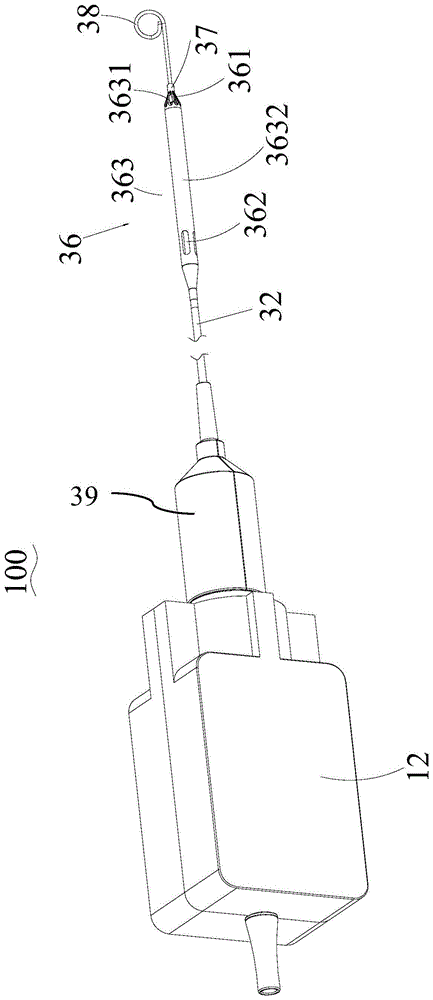
工作组件30还包括导管32、穿设在导管32中的驱动轴(未示出)、由驱动轴驱动的泵36。导管32的近端连接至耦合器39的远端。驱动轴穿设在导管32中,由转子轴44驱动。The working assembly 30 also includes a
泵36可通过导管32被输送至心脏的期望位置(例如:左心室)泵送血液,包括连接至导管32远端并具有进口端361和出口端362的泵壳363、收纳在泵壳内的叶轮(未示出),叶轮被驱动轴驱动旋转以将血液从进口端361吸入泵壳363并从出口端362排出。The
泵壳363包括由镍、钛合金制作的呈金属格构的支架3631和覆盖支架3631上的弹性覆膜3632。支架3631的金属格构具有网孔设计,覆膜3632覆盖支架3631的部分,支架3631前端未被覆膜3632覆盖的部分的网孔形成进口端361。覆膜3632的后端包覆在导管32远端外部,出口端362为形成在覆膜3632后端的开口。The
叶轮包括连接至驱动轴远端的轮毂及支撑在轮毂外壁的叶片,叶片呈螺旋状,其数量可以是一个,也可以是多个例如两个。The impeller includes a hub connected to the far end of the drive shaft and blades supported on the outer wall of the hub. The blades are helical, and the number of the blades can be one or more, such as two.
导管32远端与支架3631近端之间连接有近端轴承室(未示出)。即,支架3631通过近端轴承室与导管32连接。驱动轴穿设在位于近端轴承室中的近端轴承。支架3631的远端与保护头38(后文具体描述)之间设有远端轴承室37。即,保护头38通过远端轴承室与支架3631连接。驱动轴的远端穿设在位于远端轴承室37中的远端轴承。通过近远端轴承形成对叶轮的限位,使叶轮能较佳的被保持在泵壳363中,并使叶轮与泵壳363之间的泵间隙被稳定的保持。A proximal bearing chamber (not shown) is connected between the distal end of the
泵36为可收折式泵,具有压缩状态和展开状态。在泵36对应介入构型下,泵壳363和叶轮处于压缩状态,泵36能以较小的第一外径尺寸介入人体的脉管系统或者在受试者脉管系统中输送。在泵36对应工作构型下,泵壳363和叶轮处于展开状态,泵36能以大于第一径向尺寸的第二径向尺寸在左心室内泵送血液。The
在本领域中,泵363的尺寸与流体力学性能是两个相互矛盾的参数。简言之,出于减轻受试者痛苦和介入容易的角度,希望泵363的尺寸小。而出于为受试者提供较强的辅助功能,希望泵363的流量大,流量大一般要求泵363的尺寸大。In the art, the size and hydrodynamic performance of the
通过设置可收折的泵363,使得泵363具有较小的收折尺寸和较大的展开尺寸,以兼顾在介入/输送过程中减轻受试者痛苦且介入容易,以及提供大流量这两方面的需求。By setting the
由上述,泵壳3631的多网孔尤其是菱形网孔的设计可实现较佳的实现收折,同时借助镍钛合金的记忆特性实现展开。Based on the above, the multi-mesh design of the
泵36对应介入构型时,叶片包裹在轮毂外壁上并至少部分地与泵壳内壁接触。泵36对应工作构型时,叶片自轮毂径向向外延伸并与泵36的内壁间隔。叶片由柔弹性材料制成,在被收折时蓄能,在外界的约束撤除后,叶片的蓄能释放,使叶片展开。泵36是借助外界的约束实现收折,在约束撤除后,泵36实现自展开。When the
在本实施例中,“压缩状态”是指泵36被径向约束的状态。也就是,泵36受到外界压力被径向压缩折叠成最小径向尺寸的状态。“展开状态”是指泵36未被径向约束的状态。也就是,支架3631和叶轮径向外侧展开成最大径向尺寸的状态。In this embodiment, the "compressed state" refers to the state in which the
上述的外界约束的施加,通过滑动套设在导管32外的折叠鞘(未示出)完成。当折叠鞘在导管32外向前移动时,可将泵36整体收纳在其内,实现泵36的强制收折。当折叠鞘向后移动时,泵36受到的径向约束消失,泵36自展开。The aforementioned application of external constraints is accomplished by sliding a folded sheath (not shown) over the
由上述,泵36的收折是借助折叠鞘施加的径向约束力实现的,而泵36包含的叶轮收纳在泵壳363内。因此,实质上,泵36的收折过程是:折叠鞘对泵壳363施加径向约束力,泵壳363径向压缩时,对叶轮施加径向约束力。From the above, the
也就是,泵壳363是直接在折叠鞘的作用下被收折,而叶轮却是直接在泵壳363的作用下被收折。而如上述,叶轮具有弹性。因此,尽管处于收折状态,但叶轮收折蓄能使其始终具有径向展开的趋势,进而叶轮会与泵壳363内壁接触,并对泵壳363施加反作用力。That is, the
在折叠鞘的约束撤除后,泵壳363在自身的记忆特性作用下,支撑弹性的覆膜3632展开,叶轮在释放的蓄能作用下自展开。在展开状态下,叶轮的外径小于泵壳363的内径。这样,叶轮的径向外端(也就是叶片的叶尖)与泵壳363的内壁(具体为支架3631内壁)之间保持间隔,该间隔为泵间隙。泵间隙的存在,使得叶轮能无阻碍的旋转,而不发生碰壁。After the restraint of the folded sheath is removed, the
此外,出于流体力学方面的考虑,泵间隙尺寸为较小的数值且被维持,是期望的。在本实施例中,叶轮的外径略小于支架3631内径,使得在满足叶轮旋转不碰壁的情况下,泵间隙尽可能的小。In addition, for hydrodynamic considerations, it is desirable that the pump clearance size be kept at a small value. In this embodiment, the outer diameter of the impeller is slightly smaller than the inner diameter of the
而泵间隙保持的主要实现手段是通过支架3631提供的支撑强度,该支撑强度可抵抗流体(血液)的背压的作用而不发生变形,进而保持泵壳363的形状稳定,则泵间隙也被稳定的保持。The main means of maintaining the pump clearance is the supporting strength provided by the
下面对泵36的收折和展开过程介绍如下:Below the folding and unfolding process of the
在将泵36介入左心室的过程中,泵36由于外部施加的径向约束力而处于径向约束状态(压缩状态)。或者,泵36仅在介入受试者脉管系统中的过程是收折的。在介入至左心室中后(以收折的形态在脉管系统中向前输送),或者介入至受试者脉管系统中后(以展开的形态在脉管系统中向前输送),撤去径向约束力,支架3631利用自身的记忆特性以及叶轮的叶片借助蓄能释放而自主扩张,所以泵36自动地呈现其非约束形状(展开状态)。During insertion of the
反之,在装置100完成工作需要从受试者体内撤出时,利用折叠鞘将泵36收折,待泵36完全撤出受试者体内,再撤除折叠鞘对泵36的约束,使泵36恢复至应力最小的自然状态,也就是展开状态。Conversely, when the
保护头38是柔软的,可以由任意的宏观表现出柔性的材料制成,不伤害受试者的组织。具体而言,保护头38为端部呈圆弧状或卷绕状的柔性凸起,该柔性的端部以无创或无损伤的方式支撑在心室内壁上,将泵36的吸入口361与心室内壁隔开,避免泵36在工作过程中由于血液的反作用力而使泵36的吸入口361贴合在心室内壁上,保证泵吸的有效面积。The
驱动组件10与工作组件30通过耦合器39和马达壳12实现可拆卸地连接。由此,在准备将泵36和导管32的远端部分送入受试者体内时,可将驱动组件10与工作组件30拆卸,避免较大较重的驱动组件10影响泵36和导管32的前端部分被送入受试者体内的操作,操作更轻便。The driving
请重点参见图3和图4,驱动组件10包括由马达14的马达轴16驱动的驱动件99。工作组件30包括与驱动件99耦合以被驱动绕旋转轴线转动的从动件89,从动件89驱动驱动轴。从动件89与驱动轴之间设有转子轴44,从动件89驱动转子轴44,驱动轴与转子轴44相连,从而从动件89顺次驱动转子轴44、驱动轴和泵36。Please focus on FIGS. 3 and 4 , the driving
驱动件99和从动件89中的一个为磁力提供元件,另一个为导体,两者之间形成间隙79。磁力提供元件为自身带有磁性的磁体,例如永磁体或硬磁体。或者,磁力提供元件也可以是通电后能够产生磁性的电磁元件,例如线圈。导体可采用金属,例如导电性能较佳的铜、铝或包含铜、铝的合金等。One of the driving
马达轴16转动带动驱动件99转动后,导体会在磁力提供元件产生的磁场中切割磁力线,进而在导体中产生涡电流。而此涡电流在导体上又产生反向感应磁场,该感应磁场与磁力提供元件产生的磁场发生磁力耦合作用,从而实现从动件89与驱动件99的耦合并被驱动绕旋转轴线转动。从动件89转动带动转子轴44、驱动轴转动,最终驱动泵36。After the
尤其值得注意的是,磁力提供元件与导体耦合构成类似涡流联轴器(EddyCurrent)的动力传递结构。基于涡流联轴的工作原理,采用该结构在传动旋转动力的过程中,如果叶轮转动受阻,相较于磁耦合的动力传递方式,工作侧(驱动轴或叶轮)的转速并不会明显下降。因此,其具备一定的离合器功能,在保护心室组织的情况下,又不会使泵血流量发生显著的下降,从而大幅降低由于血流量下降以及装置的介入而生成血栓的风险。It is particularly worth noting that the coupling between the magnetic force providing element and the conductor constitutes a power transmission structure similar to an eddy current coupling (EddyCurrent). Based on the working principle of the eddy current coupling, when using this structure to transmit the rotating power, if the rotation of the impeller is blocked, compared with the power transmission method of magnetic coupling, the speed of the working side (drive shaft or impeller) will not drop significantly. Therefore, it has a certain clutch function, and in the case of protecting the ventricular tissue, it will not significantly reduce the pump blood flow, thereby greatly reducing the risk of thrombus formation due to the decrease of blood flow and the intervention of the device.
而且基于涡流联轴的工作原理,驱动件与从动件的转速差,亦正是其能耦合的原因。因此,在阻碍叶轮旋转的阻力消失后,只要马达还在正常工作,那么从动件自动的实现复转,而无需停机后再重启马达。从而,为受试者提供心室辅助的持续性较佳,且这种持续性不依赖复杂的监测和控制手段,临床稳定性更高。Moreover, based on the working principle of the eddy current coupling, the speed difference between the driving part and the driven part is also the reason why it can be coupled. Therefore, after the resistance to the rotation of the impeller disappears, as long as the motor is still working normally, the follower will automatically realize the re-rotation without restarting the motor after stopping the machine. Therefore, the continuity of providing ventricular assistance to the subject is better, and this continuity does not depend on complex monitoring and control means, and the clinical stability is higher.
驱动件99和从动件89之间的间隙79,使得驱动件99和从动件89的磁力耦合实现非接触式动力传递,有利于实现对流体的密封,防止液体进入马达14。The
上述液体为装置100运行过程中需灌注至人体内的Purge液,该Purge液为可部分维持人体机能所需的生理液,例如生理盐水、葡萄糖溶液、抗凝剂,或者上述任意的组合。为了将Purge液顺利灌注至人体内,装置100包括灌注系统,该灌注系统包括壳体、通过管路与耦合器39连通的灌注泵。壳体中设置的控制单元(下文所述第二控制单元)控制灌注泵运转,灌注泵通过管路向耦合器39中注入Purge液,并通过工作组件30中的管路系统将Purge液注入人体内。The above-mentioned liquid is the Purge liquid that needs to be poured into the human body during the operation of the
导管32近端与耦合器39连接并液体连通,耦合器39上设有适于与管路连接接口,灌注泵将Purge液体经由该接口注入耦合器39中后,进入导管32,在导管32中向前流动。在此过程中,润滑驱动轴,并冲刷近端轴承,实现润滑。The proximal end of the
间隙79构造为磁力提供元件的充磁面与导体面对充磁面的表面之间的距离。驱动件99与从动件89之间需要有间隙79,但间隙79太大会影响传动效率。因此,本实施例中,间隙79的宽度小于等于5mm。间隙79的宽度进一步小于4mm,更进一步小于3mm,再进一步小于2mm,尤其进一步小于1mm。The
值得注意的是,上述数值包括从下限值到上限值之间以一个单位递增的下值和上值的所有值,在任何下值和任何更高值之间存在至少两个单位的间隔即可。It should be noted that the above values include all values from the lower value to the upper value in increments of one unit for the lower and upper values, with a separation of at least two units between any lower value and any higher value That's it.
举例来说,阐述的间隙79的宽度小于等于5mm,优选为0.5-4.5mm,更优选为1-4mm,进一步优选为1.5-3.5mm,目的是为说明上述未明确列举的诸如2mm、2.5mm、3mm值。For example, the width of the stated
如上述,整数的示例范围,并不能排除以适当的单位例如0.1、0.2、0.3、0.5等数值单位为间隔的增长。这些仅仅是想要明确表达的示例,可以认为在最低值和最高值之间列举的数值的所有可能组合都是以类似方式在该说明书明确地阐述了的。As mentioned above, the exemplary ranges of integers do not preclude increments at intervals of numerical units such as 0.1, 0.2, 0.3, 0.5 etc. as appropriate. These are merely examples intended to be expressly stated, and it is considered that all possible combinations of numerical values recited between the lowest value and the highest value are expressly set forth in this specification in a similar manner.
除非另有说明,所有范围都包括端点以及端点之间的所有数字。与范围一起使用的“大约”或“近似”适合于该范围的两个端点。Unless otherwise indicated, all ranges include the endpoints and all numbers between the endpoints. "About" or "approximately" used with a range applies to both endpoints of the range.
本文中出现的其他关于数值范围的限定,可参照上述描述,不再赘述。For other limitations on the numerical range presented herein, reference may be made to the above description, and details are not repeated here.
为将驱动件99的磁力线沿朝向从动件89的方向约束,驱动件99背离从动件89的一侧设有第一磁力约束件71。第一磁力约束件71由导磁材料制成,例如可以包括实心背铁、平行磁通硅钢片背铁、垂直磁通硅钢片背铁等。第一磁力约束件71与驱动件99同步运动。In order to constrain the magnetic force lines of the driving
同样的,为将从动件89的磁力线朝驱动件99的方向约束,从动件89背离驱动件99的一侧设有第二磁力约束件72。第二磁力约束件72由导磁材料制成,可参照上述描述,不作赘述。第二磁力约束件72与从动件89同步运动。Similarly, in order to constrain the magnetic force lines of the
第一和第二磁力约束件71、72配合将磁力线约束在驱动件99与从动件89之间,使两者之间的磁力被最大限度的增强,从而提高传动效率。The first and second
以上描述了本发明实施例的驱动件99与从动件89之间的涡电流传动原理,下面通过不同实施例,描述具体的传动结构。这些传动结构的原理相同,不再赘述。The eddy current transmission principle between the driving
请参见图4,示出了本发明第一实施例的部分传动机构。Please refer to FIG. 4 , which shows part of the transmission mechanism of the first embodiment of the present invention.
在本实施例中,驱动件99的远端端面和从动件89的近端端面相对,构造成端面耦合。驱动件99包括主体993、与主体993远离从动件89的一侧相连的连接部995。主体993呈盘状,连接部995呈管状或空心柱体状,马达轴16插入连接部995,实现马达轴16对驱动件99的驱动。In this embodiment, the distal end surface of the driving
从动件89呈环状,转子轴44插入环状从动件89的中心孔与从动件89相连,转子轴44的近端端面与从动件89的近端端面平齐。驱动件99的远端端面与从动件89的近端端面之间的间隙79小于等于5mm。The
第一磁力约束件71将驱动件99的磁力线约束在第一磁力约束件71的远侧,避免驱动件99的磁力线向背离从动件89的方向扩散。第一磁力约束件71呈环状,套设于驱动件99的连接部995,且第一磁力约束件71与驱动件99的主体993的近端面抵接,结构紧凑。The first magnetic constraining
第一磁力约束件71与驱动件99同步运动。一种方式是,第一磁力约束件71与驱动件99的连接部995外表面紧配实现第一磁力约束件71与驱动件99同步运动。另一种方式是,第一磁力约束件71与驱动件99的近端面通过某种连接方式,如粘连实现第一磁力约束件71与驱动件99同步运动。The first magnetic constraining
当然,其他实现第一磁力约束件71与驱动件99同步运动的方式亦可,凡采用与本实施例相同或类似的方案均涵盖在本发明的保护范围内。Of course, other ways to realize the synchronous movement of the first magnetic constraining
同样的,第二磁力约束件72将从动件89的磁力线约束在第二磁力约束件72的近侧,避免从动件89的磁力线向背离驱动件99的方向扩散。第二磁力约束件72与从动件89同步运动,实现方式参照上文描述,不再赘述。Likewise, the second
从动件89与驱动件99通过涡流传动实现磁耦合并顺次驱动转子轴44、驱动轴和泵36的叶轮,且第一和第二磁力约束件71、72配合将磁力线约束在两者之间,使传动高效。The driven
请参见图5,示出了本发明的第二实施例的部分传动机构。Please refer to FIG. 5 , which shows a part of the transmission mechanism of the second embodiment of the present invention.
以US7393181 B2为代表的已知实施例,提供了符合上述需求的方案,并基本上开启了可折叠式心室辅助装置(简称血泵)的先河。血泵的可折叠,体现在泵头(包括泵壳和叶轮)在介入过程中收折,在介入到位后展开。优点是既可以减小介入尺寸,进而减少感染和并发症,并降低患者痛苦,又可以在泵头工作时获得最佳的水利学性能。The known embodiment represented by US7393181 B2 provides a solution that meets the above-mentioned needs, and basically opens the precedent of a collapsible ventricular assist device (abbreviated as a blood pump). The foldability of the blood pump is reflected in the fact that the pump head (including the pump casing and impeller) is folded during the intervention and unfolded after the intervention is in place. The advantage is that it can reduce the size of the intervention, thereby reducing infection and complications, and reducing patient pain, and can also obtain the best hydraulic performance when the pump head is working.
可折叠式血泵的泵头(具体为叶轮)一般借助一根很长的软轴被位于体外的马达驱动运转。在驱动的过程中,旋转的软轴难以避免地会与收纳其的导管的内壁发生摩擦,进而发热。这种发热会加剧软轴与导管的磨损,导致上述部件的寿命缩减。同样的问题,还存在于整个传动链路中的其他旋转部件,例如轴承。The pump head (specifically the impeller) of the collapsible blood pump is generally driven by a motor located outside the body by means of a very long flexible shaft. During the driving process, the rotating flexible shaft will inevitably rub against the inner wall of the catheter that accommodates it, thereby generating heat. This heating increases the wear of the flexible shaft and the catheter, resulting in a shortened life of these components. The same problem also exists in other rotating parts in the whole transmission chain, such as bearings.
因此,以US8591393B2为代表的已知实施例,提供了在可折叠式血泵处于工作过程时,对上述很长的传动链路进行冷却和/或润滑的方案。大体的过程为:体外的流体供应源向导管中灌注流体,该流体对旋转的软轴和轴承进行润滑,降低摩擦产热量,并及时对产热进行冷却。Therefore, the known embodiment represented by US8591393B2 provides a solution for cooling and/or lubricating the above-mentioned very long transmission link when the collapsible blood pump is in operation. The general process is: the fluid supply source outside the body pours fluid into the catheter, and the fluid lubricates the rotating flexible shaft and bearings, reduces the heat generated by friction, and cools the heat generated in time.
不过,引入的起冷却/润滑作用的流体,随之产生的另一个问题-密封,不得不被关注。本质上来说,是不希望灌注的流体进入马达,以避免马达被损坏。However, the introduction of cooling/lubricating fluids, and the ensuing problem of sealing, has to be taken care of. Essentially, you don't want priming fluid to get into the motor, lest it get damaged.
因此,如何将马达的旋转动力借由软轴传递至泵头的叶轮,并在此过程中避免灌注液体进入马达,一直以来都是本领域的迫切需要解决的问题。Therefore, how to transmit the rotational power of the motor to the impeller of the pump head through the flexible shaft and prevent the perfusion liquid from entering the motor during the process has always been an urgent problem in this field.
本实施例与图4所示的第一实施例的区别在于,在驱动件99与从动件89的间隙79中设有液体隔离壁75,从而有利于实现对流体的密封,防止液体进入马达14。The difference between this embodiment and the first embodiment shown in FIG. 4 is that a
装置100运行过程中需向人体内灌注Purge液。如上述,Purge液如果流至马达14内部,可能会导致马达14损坏而造成装置故障。因此,在驱动件99与从动件89的间隙79中设置液体隔离壁75可有效避免液体注入马达14。During the operation of the
另外,工作组件30的一系列传动过程中会产生热量,加剧部件的磨损。因此,需要对工作组件30进行热管理。液体隔离壁75限定了液体的流动方向,使液体只能向前端也就是工作组件30流动,从而可对工作组件30起到降温的作用。In addition, heat will be generated during a series of transmissions of the working assembly 30, which will aggravate the wear of the components. Accordingly, thermal management of the working assembly 30 is required. The
液体隔离壁75围设从动件89的至少部分端面和至少部分侧面,从而更好的起到避免液体流至马达14内造成马达14损坏,更均匀高效的对工作组件30进行热管理的效果。The
从动件89外设有液体隔离层(未示出),用于隔离液体与从动件89的接触。该液体即为上文提及的Purge液。液体隔离壁隔离液体与从动件89的接触,可避免液体腐蚀从动件89,进而最大限度的保持从动件89的性能。The
具体而言,在从动件89作为磁力提供元件的实施例中,液体隔离可避免磁体或线圈被液体侵蚀而导致磁力衰弱,尽可能延长从动件89提供磁力的寿命。而在从动件89作为导体的实施例中,液体隔离可避免导体被侵蚀而导致导电性能下降,保证从动件89产生涡电流进而产生感应磁场的性能稳定。Specifically, in the embodiment where the
在一实施方式中,液体隔离层可以为防水涂层,例如钛镀层。防水涂层可以轻薄而有效的隔绝液体与从动件89的接触。防水涂层构造成的液体隔离层具有厚度薄、质轻、易成形和结合强度高等优势,而这些优势将对耦合效率、装配、制作成本和使用寿命等方面提供有益的促进。In one embodiment, the liquid barrier layer may be a waterproof coating, such as a titanium coating. The waterproof coating can be light and thin but effectively isolate the contact between the liquid and the
在另一实施方式中,液体隔离层可为包裹或包覆从动件89的机械结构例如树脂封装,形成将从动件89收纳在其内的收纳腔。同上述防水涂层的实施例,收纳腔可以可靠地保护从动件89,可靠地隔离液体侵蚀从动件89。In another embodiment, the liquid isolation layer can be a mechanical structure that wraps or wraps the
请参见图6,示出了本发明的第三实施例的部分传动机构。Please refer to FIG. 6 , which shows a part of the transmission mechanism of the third embodiment of the present invention.
与第一实施例不同的是,在本实施例中,驱动件993和从动件893的内外周面相对实现涡流传动,构造成径向耦合。Different from the first embodiment, in this embodiment, the inner and outer peripheral surfaces of the driving
无论是端面相对还是内外周面相对实现传动,原理一致,不再赘述。需要说明的是,“周面”可以是“圆周面”,也可以是其他形状的周面。Regardless of whether the end faces are facing each other or the inner and outer peripheral faces are facing each other to realize the transmission, the principle is the same and will not be repeated here. It should be noted that the "circumferential surface" may be a "circumferential surface" or a peripheral surface of other shapes.
具体的,驱动件993与从动件893在旋转轴线的周向上至少部分重合,在旋转轴线的径向上间隔设置而具有间隙79。或者说,驱动件993包括通道73,从动件893设在通道73中。Specifically, the driving
更具体的,驱动件993和从动件893为沿周向连续的环状,或者,驱动件993和从动件893包括多个沿圆周方向间隔设置的环状段。需要说明的是,驱动件993和从动件893在周向上至少部分重合,并不严格要求驱动件993和从动件893为圆环状或圆环段状,其他形状的环状亦可。More specifically, the driving
为了安装驱动件993,马达轴16连接有第一支架51,第一支架51包括第一中空部52,驱动件993设在第一中空部52的外壁,第一磁力约束件713设在驱动件993的径向外侧。In order to install the driving
第一磁力约束件713的作用与前述实施例相同,不再赘述。The function of the first magnetic constraining
第一支架51包括与第一中空部52相连的安装部53,安装部53设有可安装马达轴16的安装孔,第一支架51被马达轴16驱动旋转而带动驱动件993旋转。第一支架51还包括与第一中空部52相连的限位部54,限位部54自第一中空部52的远端径向向外延伸,限位部54的延伸方向与第一中空部52的延伸方向垂直。驱动件993同时与第一中空部52和限位部54抵接。优选的,第一支架51的第一中空部52、安装部53、限位部54一体成型。限位部54与驱动件993的外周面平齐,第一磁力约束件713、驱动件993与限位部54的外周面贴合,而将驱动件993的磁力线约束在第一磁力约束件713的内侧。The
当然,可以理解,第一磁力约束件713仅与驱动件993的外周面贴合亦可,凡采用与本实施例相同或类似的方案均涵盖在本发明的保护范围内。Of course, it can be understood that the first magnetic constraining
从动件893具有通孔,转子轴44插入通孔与从动件893相连,实现从动件893旋转带动转子轴44旋转。转子轴44的近端面与从动件893的近端面平齐。The
工作组件30还包括第二磁力约束件723,第二磁力约束件723设于转子轴44与从动件893之间,第二磁力约束件723连接从动件893和转子轴44。第二磁力约束件723套设在转子轴44的外周面,从动件893套设在第二磁力约束件723的外周面。第二磁力约束件723将从动件893的磁力线约束在第二磁力约束件723的外侧。第二磁力约束件723的轴向长度与从动件893轴向长度相同,且第二磁力约束件723与从动件893在轴向上对齐设置,即两者的近端面和远端面均平齐。The working assembly 30 further includes a second magnetic constraining
由此,马达轴16旋转带动第一支架51旋转,第一支架51旋转带动驱动件993旋转,驱动件993旋转通过涡流传动带动从动件893旋转,从动件893旋转带动转子轴44旋转,从而通过驱动轴驱动泵36工作。第一磁力约束件713和第二磁力约束件723配合将磁力线约束在两者之间。Thus, the rotation of the
在替换实施例中,第二磁力约束件723与转子轴44一体设置。或者说,转子轴44本身由导磁材料制成,转子轴44本身构造为第二磁力约束件723,则可取消设置独立的第二磁力约束件723,结构更简单。In an alternative embodiment, the second
在本实施例中,驱动件993形成通道,从动件893至少部分伸入通道中。在其他一些替换实施例中,从动件893包括通道,驱动件993设在通道中。In this embodiment, the driving
在本实施例中,马达轴16与第一支架51相连,驱动件993与第一支架51相连,或第一支架51本身构成为驱动件993。在其他一些替换实施例中,转子轴44连接有第二支架,第二支架包括第二中空部,从动件893设在第二中空部的外壁,第二中空部构造成第二磁力约束件;或者,从动件893设在第二中空部的内壁,第二磁力约束件设在从动件893的径向内侧。In this embodiment, the
与第二实施例相同,本实施例中亦在间隙79中设有液体隔离壁75,不再赘述。Same as the second embodiment, in this embodiment, a
装置100工作时,马达轴16带动驱动件993旋转,从动件893与驱动件993耦合,从动件893被驱动件993驱动旋转,从动件893旋转顺次驱动转子轴44、驱动轴旋转,驱动轴旋转而驱动泵36实现泵血功能。When the
请参见图7,示出了本发明的第四实施例的部分传动机构。Please refer to FIG. 7 , which shows a part of the transmission mechanism of the fourth embodiment of the present invention.
如上述,基于涡流联轴的传动原理,驱动件993和从动件893的转速并不同步。并且,正是由于这种转速不同步,才能通过导体中产生的涡电流、反向感应磁场而实现驱动件993和从动件893的耦合。简言之,马达轴16与驱动轴或者叶轮之间必然存在转速差。As mentioned above, based on the transmission principle of the eddy current coupling, the rotational speeds of the driving
如果马达轴16与驱动轴之间不存在转速差,控制模块通过直接检测及控制马达轴16的转速即可间接控制驱动轴或者叶轮的转速,使叶轮的转速在合理的范围内,从而使泵满足工作所需。If there is no speed difference between the
而本发明中,驱动件993和从动件893的耦合方式决定了马达轴16和驱动轴之间必然存在速度差(通常情况下,驱动轴的转速低于马达轴16的转速)。那么,控制模块及时了解驱动轴的转速,对驱动轴的控制及泵的正常工作十分必要。为此,装置100包括与控制模块通讯连接的转速侦测组件,用于检测驱动轴的转速。However, in the present invention, the coupling mode of the driving
当控制模块在基于转速侦测组件提供的信号而判断驱动轴的转速低于目标转速时,控制马达14提高转速,从而提高驱动轴的转速,使驱动轴的转速调整至目标转速附近。需要说明的是,当驱动轴的转速相对目标转速上下浮动的范围在10%,优选为5%,进一步优选为1%以内时,则控制模块判断驱动轴的转速在目标转速附近。When the control module judges that the speed of the drive shaft is lower than the target speed based on the signal provided by the speed detection component, it controls the
当控制模块在基于转速侦测组件提供的信号而判断驱动轴的转速在目标转速附近时,控制马达14维持当前转速,从而使驱动轴的转速维持在目标转速附近。When the control module determines that the rotational speed of the drive shaft is near the target rotational speed based on the signal provided by the rotational speed detection component, the
优选的,装置100还包括与控制模块电连接或通讯连接的告警单元,控制模块在基于转速侦测组件提供的信号而判断驱动轴的转速低于目标转速,但马达14的转速高于设定值时,控制告警单元操作。也就是说,当马达14的转速高于设定值,理论上,驱动轴的转速不会低于目标转速,在这种情况下,如果检测到驱动轴的转速却低于目标转速,则说明,马达14至驱动轴的传动链路出现问题,例如叶轮或驱动轴存在转动阻力,导致叶轮或驱动轴相较于马达轴16存在失速问题。此时,告警单元发出报警信号,使操作者(例如医生)及时获知该情况,从而及时采取对应的措施,进而提升安全性。告警单元例如可以是声音报警、光闪烁报警以及两者的结合报警等。Preferably, the
控制模块包括集成在马达14中的第一控制单元、设在灌注系统的壳体中第二控制单元。第一控制单元可向马达14提供经转换后的电平信号,还可向马达14提供反向电气隔离。第二控制单元与转速侦测组件电连接或通讯连接,并控制马达14和灌注泵操作。The control module comprises a first control unit integrated in the
第一控制单元为第一PCB单元,作用包括:第一,向马达14提供合适的电压,从而实现电压转换,例如可将高电平转换成低电平,或者将低电平转换成高电平,然后再提供给马达14。第二,电气隔离,使得电子电气相关法规基于安全性的要求。例如,当介入侧有其他高压场景例如除颤仪通过导电的软轴反向传递至马达14,可能导致装置100失效及损坏,因此需要电气隔离。The first control unit is the first PCB unit, and its functions include: first, supplying a suitable voltage to the
第二控制单元是第二PCB单元,作用包括:控制马达14的运转。例如基于接收到的信号,控制马达14的转速。其中,上述信号至少包括:转速电信号,然后第二PCB单元将转速电信号(电压)转换成转速信息,进行判断,进而进行转速控制。第二PCB单元的作用还包括控制灌注系统中的马达(注射泵马达),从而控制Purge液的灌注。The second control unit is a second PCB unit, and its functions include: controlling the operation of the
由于控制模块包括分开设置的第一PCB单元和第二PCB单元,则第一PCB单元和第二PCB单元可以分别设在不同的位置且各司其职,而不用全部设在马达14中,从而可以减少马达14的尺寸。Since the control module includes a first PCB unit and a second PCB unit that are separately arranged, the first PCB unit and the second PCB unit can be respectively arranged in different positions and perform their own duties, instead of all being arranged in the
下面重点描述本实施例与第三实施例的区别。The difference between this embodiment and the third embodiment will be mainly described below.
为了检测驱动轴的转速,转速侦测组件包括与驱动轴同步转动的同步器202、检测同步器202转速的传感器204,传感器204与控制模块电连通或通讯连接。In order to detect the rotational speed of the drive shaft, the rotational speed detection component includes a
传感器204可检测驱动轴的转速,并将驱动轴的转速信息传递至控制模块,控制模块可判断驱动轴的转速是否满足需要,并判断是否需要通过调整马达14的转速进而调整驱动件994的转速,最终将驱动轴的转速控制在需要的范围内,从而满足由驱动轴驱动的泵的工作需要。The
例如,在一种场景下,控制模块判断驱动轴的转速低于最低要求,则可通过提高马达14的转速,从而通过驱动件994、从动件894的耦合而提高驱动轴的转速,进而满足泵的工作需要。当然,反向控制亦可,不再赘述。For example, in one scenario, if the control module judges that the speed of the drive shaft is lower than the minimum requirement, the speed of the drive shaft can be increased by increasing the speed of the
在一种实施方式中,同步器202为磁力提供元件,传感器204为线圈。根据电磁感应原理,磁力提供元件随驱动轴同步转动过程中,线圈中会产生电流,而且磁力提供元件以不同的速度转动时,线圈中的电流的大小会发生变化,线圈与控制模块电连接或通讯连接,控制模块通过线圈的电流大小的变化,通过一定的计算即可确定磁力提供元件的转速,从而确定驱动轴的转速,并根据需要判断是否需要调整马达14的转速,从而调整驱动轴的转速。In one embodiment, the
在本发明的其它实施例中,转速侦测组件可通过光栅、光反射、频闪仪等原理实现,凡采用与本实施方式相同或类似的方案均涵盖在本发明的保护范围内。In other embodiments of the present invention, the rotational speed detection component can be realized by grating, light reflection, stroboscope and other principles, and any solution that is the same as or similar to this embodiment is covered within the protection scope of the present invention.
在另一种实施方式中,同步器202为磁力提供元件,传感器204为霍尔传感器。当磁力提供元件以不同的速度转动时,霍尔传感器会发出不同的脉冲信号,控制模块可通过检测霍尔传感器发出的脉冲信号的变化并通过一定的计算获得驱动轴的转速,并根据需要判断是否需要调整马达的转速,从而调整驱动轴的转速。In another embodiment, the
由于霍尔传感器是一种技术相对成熟的传感器204,只需要选用购买合适的传感器即可,对装置的设计和制造更简单。Since the Hall sensor is a
如前所述,从动件894与驱动轴之间设有转子轴44,从动件894安装于转子轴44并驱动转子轴44,驱动轴与转子轴44相连,从而从动件894顺次驱动转子轴44、驱动轴和泵。As mentioned above, the
装置工作时,驱动轴的远端部分随导管被送入受试者体内,驱动轴包括可弯曲的软轴,软轴可发生肉眼可见的变形。转子轴44安装从动件894,转子轴44为硬轴,可使从动件894的安装更稳定、运行更可靠。When the device is working, the distal part of the driving shaft is sent into the body of the subject along with the catheter, and the driving shaft includes a flexible flexible shaft, which can be deformed visible to the naked eye. The
同步器202设在转子轴44。也就是说,同步器202随转子轴44转动过程中,同步器202与传感器204的位置不会发生变化,传感器204对同步器202的转速检测更精准。The
如前所述,同步器202为磁力提供元件,而同步器202设在转子轴44。优选的,转子轴44由非导磁材料制成。非导磁材料,例如可以是不锈钢、陶瓷、高分子材料以及这些材料的组合。由此,转子轴44本身不会对同步器202的磁场造成影响,这使得传感器204对同步器202的转速的检测更加精准。As previously mentioned, the
装置100在使用过程中处于液体环境中,液体环境对同步器202的运行不够友好,例如,当同步器202为磁力提供元件时,如果磁力提供元件接触液体,液体会对磁力提供元件造成侵蚀,从而导致磁力衰弱。为了防止液体对同步器202的侵蚀,同步器202外包覆外壳206,外壳206与转子轴44周向固定。The
外壳206将同步器202与液体环境相隔离,使同步器202处于良好的工作状态。外壳206将同步器202包覆在其内,即外壳206形成收容空间,同步器202与收容空间形状匹配,从而同步器202与外壳206同步运动。外壳206与转子轴44周向固定,即外壳206与转子轴44同步转动,保证同步器202与转子轴44同步转动,从而准确测量转子轴44及驱动轴的转速,从而为马达14是否调整转速提供可靠支持。The
外壳206与转子轴44实现同步运动的方式,例如可以是外壳206与转子轴44紧配,或者,外壳206与转子轴44扁方配合。外壳206与转子轴44扁方配合,即转子轴44的横截面为非圆形。具体的,转子轴44的周面包括第一表面和第二表面,第一表面或第一表面的外切面与第二表面或第二表面的外切面呈角度设置。外壳206具有可供转子轴44插入的中心通道,该中心通道的表面与转子轴44的周面形状匹配,从而实现外壳206与转子轴44扁方配合,使外壳206及同步器202与转子轴44同步转动。The manner in which the
外壳206由绝缘材料制成,避免同步器202与可能的电流产生相互的影响。The
在一个实施例中,外壳206包括第一部分208和第二部分210,第一部分208和第二部分210独立制造并通过配合形成收纳同步器202的空间。由此,安装时,将同步器202安装于第一部分208后,在将第二部分210与第一部分208配接,即可将同步器202封装在外壳206中。In one embodiment, the
在另一个实施例中,同步器202可以在外壳206一体注塑,从而使外壳206更好的包覆同步器202。In another embodiment, the
同步器202设在液体隔离壁75的径向内侧,传感器204设在液体隔离壁75的径向外侧。从而,液体隔离壁75使同步器202和传感器204间隔设置,保证同步器202、传感器204的正常工作。而且,合理利用液体隔离壁75两侧的空间,有利于装置的小型化。The
由此可以看出:同步器202封装于外壳206中,外壳206与转子轴44周向固定,从而同步器202与转子轴44周向固定,两者基本无相对转动。当转子轴44以一定的转速转动时,同步器202与转子轴44同步转动。同步器202以不同的转速转动时,传感器204中会产生信号的变化,而传感器204与装置的控制模块电连接或通讯连接,控制模块检测到信号的变化后,通过一定的计算,可确定同步器202的转速,从而确定转子轴44及驱动轴的转速(驱动轴与转子轴44同步转动),并判断驱动轴的转速是否在合理的范围内。如果驱动轴的转速不在合理的范围内,控制模块可通过调整马达的转速而调整转子轴44、驱动轴的转速,从而保证泵正常工作。It can be seen from this that the
在装置工作过程中,同步器202、传感器204、控制模块处于动态调整过程中。即,控制模块按上述描述调整转子轴44的转速后,同步器202、传感器204会再次反馈转子轴44的转速给控制模块,控制模块根据需要确定是否需要进一步调整。如此反复,始终保证泵在相对稳定的状态下工作。During the working process of the device, the
请参见图8和图9,示出了本发明的第五实施例的部分传动机构。Please refer to Fig. 8 and Fig. 9, which show part of the transmission mechanism of the fifth embodiment of the present invention.
在本实施例中,从动件895为磁力提供元件,具体的为磁环,磁环与转子轴44之间设有第二磁力约束件725。第二磁力约束件725为环状的背铁,套设在转子轴44上,从动件895套设在第二磁力约束件725上,且第二磁力约束件725与从动件895的两个端部平齐。In this embodiment, the
为了防止液体对从动件895造成侵蚀,转子轴44的两端分别设有位于从动件895两个端侧的第一和第二端盖231、232,第一和第二端盖231、232在轴向上为从动件895提供密封。第一和第二端盖231、232呈圆盘状,具有一定的厚度。与转子轴44紧配,从而为从动件895提供轴向上的密封保护。In order to prevent the liquid from corroding the
第一和第二端盖231、232的外径大于从动件895外径。或者说,第一和第二端盖231、232在径向上延伸超出从动件895。从动件895径向外侧设有保护层234,保护层234与第一和第二端盖231、232相连将从动件895包覆在其内,保护层234在径向上为从动件895提供密封。The outer diameters of the first and second end caps 231 , 232 are larger than the outer diameter of the
保护层234呈空心圆筒状,与第一和第二端盖231、232在径向上超出从动件895的部分连接,从而保护层234与第一和第二端盖231、232配合形成收容从动件895的收容腔。优选的,第一和第二端盖231、232上设有台阶面,保护层234与台阶面配合,保护层234的外侧面未超出第一和第二端盖231、232的径向外表面。更优选的,保护层234的外侧面与第一和第二端盖231、232的径向外表面齐平。由此,第一和第二端盖231、232、保护层234、转子轴44配合将从动件895完全包覆在其内,从而防止液体侵蚀从动件895。可以理解,第二磁力约束件725设在从动件895与转子轴44之间,则第一和第二端盖231、232、保护层234、转子轴44配合亦将第二磁力约束件725完全包覆在其内,防止液体侵蚀第二磁力约束件725。The
由于加工、装配、材料均匀性不一致等原因,可能且较大概率会导致转子轴44的质心偏移轴线,在转子轴44高转速过程中,会引发振动,额外的振动会导致某些问题,例如不利于设置液体隔离壁75的间隙79稳定保持。Due to inconsistencies in processing, assembly, material uniformity, etc., it is possible and highly probable that the center of mass of the
为了降低振动,第一端盖231和/或第二端盖232包括相连的主体和配平部(未示出)。配平部可以实现第一端盖231和/或第二端盖232对转子轴44的平衡,从而降低振动。To reduce vibration, the
在一个实施例中,配平部为自主体的一个端面向另一个端面延伸的开孔,开孔的延伸长度小于端盖的厚度。也就是说,配平部对主体进行了减重,从而实现了配平、降低振动。为了更好的实现配平,第一端盖231和/或第二端盖232优选采用密度相对较大的金属材料或陶瓷材料制成,减重配平的效果更明显。第一端盖231和/或第二端盖232的厚度大于制成金属材料能被加工的最小厚度,优选大于制成材料能被加工的最小厚度的10%,进一步大于30%,更进一步大于50%,但不大于制成材料能被加工的最小厚度的20倍。In one embodiment, the trim portion is an opening extending from one end of the main body to the other end, and the extending length of the opening is less than the thickness of the end cover. That is to say, the trim part reduces the weight of the main body, thereby achieving trim and reducing vibration. In order to achieve better balance, the
例如,第一端盖231和/或第二端盖232的制成材料能被加工的最小厚度是0.3mm,则第一端盖231和/或第二端盖232的实际设计厚度大于等于0.3mm,小于等于10mm。优选的,主体的厚度大于1mm,小于等于8mm。For example, the minimum thickness of the material that can be processed by the
该设计的主要目的,是借助金属或陶瓷质端盖的减重配平来实现期望的动平衡同时,尽快缩减端盖的厚度,以兼顾振动最优化和结构小型化的需求。The main purpose of this design is to achieve the desired dynamic balance by means of metal or ceramic end cover weight reduction and balance, and at the same time reduce the thickness of the end cover as soon as possible to meet the needs of dynamic optimization and structural miniaturization.
在另一个实施例中,主体和配平部叠置,配平部包括开孔或加重块。也就是说,配平部对主体进行了加重,而配平部本身可以做减重或加重处理,从而更大程度地实现第一端盖231和/或第二端盖232对转子轴44进行配平。In another embodiment, the main body and the trim portion are stacked, and the trim portion includes an aperture or a weight. That is to say, the trim part adds weight to the main body, and the trim part itself can be lightened or weighted, so that the
第二端盖232设在转子轴44安装驱动轴的一侧,第二端盖232相对第一端盖231靠近驱动轴,在泵的工作过程中,在概率上,第二端盖232相对第一端盖231更容易振动。为了更大程度的减少振动,第二端盖232的厚度大于第一端盖231的厚度。也就是说,在第二端盖232上可以有更大的空间对第二端盖232设置配平部,从而更大程度地对第二端盖232进行配平设计,从而更大程度地实现第二端盖232减轻转子轴44振动的效果。The
转子轴44在第一端盖231远离第二端盖232的一侧设有第一轴承235,在第二端盖232远离第一端盖231的一侧设有第二轴承236,第一轴承235和第二轴承236可对转子轴44起支撑作用。与第二端盖232的厚度大于第一端盖231的厚度原理一致,第二轴承236的尺寸大于第一轴承235的尺寸。具体的,第二轴承236的厚度大于第一轴承235的厚度,第二轴承236的径向尺寸大于第一轴承235的径向尺寸。如此设置,第二轴承236与第一轴承235配合,可以更稳定的支撑转子轴44,进一步减轻振动。The
为方便描述,将能送入受试者体内的部分称为进入组件。For the convenience of description, the part that can be delivered into the body of the subject is called the access component.
为了将进入组件顺利送入受试者体内,装置还包括贯穿工作组件的导引通道237。使用时,先将起引导作用的导丝(未示出)经脉管系统送入受试者体内。随后,用户(一般为医护人员)手持进入组件,将导丝的近端穿入导引通道237的远端,直至导丝穿过整个工作组件,使其近端从工作组件的近端穿出。随后,泵沿着导丝在受试者的脉管系统中建立的引导路径被向左心室输送,至泵的近端被送入左心室后,抽出导丝,工作组件连接上驱动组件,激活马达14,即可工作。In order to smoothly send the access component into the body of the subject, the device further includes a
导引通道237包含位于近端侧的端侧出口238,如图8所示,液体隔离壁75包括位于间隙79中并将从动转子包覆在其内的筒体部分、以及位于筒体部分端部的翻边部分,翻边部分在耦合器39与马达14接合时被压紧在耦合器39与马达壳12之间。这使液体隔离壁75能被压紧,从而保证液体密封效果。The
液体隔离壁75包括近端部,端侧出口238设在液体隔离壁75的近端部,以供导丝穿过。端侧出口238设在液体隔离壁75的近端部。端侧出口238构成灌注通道的一部分。因此,端侧出口238需要做可重复打开或密封的设计。The
具体而言,端侧出口238中设置具有可重复密封的密封件240。密封件240具有两种状态:密封状态和打开状态。当密封件240处于第一状态时,密封件240关闭端侧出口238,避免Purge液从端侧出口238流出而侵蚀马达。当密封件240处于第二状态时,端侧出口238打开,可供导丝穿过,将进入组件送入受试者体内。Specifically, a
当需要穿导丝时,将密封件240打开,使导丝穿过端侧开口,确保泵进入受试者体内。在完成泵的介入后,抽离导丝,将密封件240密封,避免泵在工作过程中Purge液渗漏。When it is necessary to pass the guide wire, the sealing
在一个实施例中,密封件240包括可在端侧出口238中沿轴向移动的柔性密封塞241,柔性密封塞241外壁和/或端侧出口238内壁倾斜设计,以使柔性密封塞241沿轴向朝第一方向移动时被挤压而切换至第一状态,沿与第一方向相反的第二方向移动时径向膨胀而切换至第二状态。In one embodiment, the sealing
密封件240还包括与柔性密封塞241相连的硬性操作部242,操作部的硬度大于柔性密封塞241的硬度,操作部相对柔性密封塞241远离端侧出口238。The
图9a示至图9e示出了不同具体示例性的密封件240的立体图和正视图。Figures 9a to 9e show perspective and front views of different specific
可以看出:操作部242和柔性密封塞241之间可以通过连接部243连接;操作部242和柔性密封塞241也可以直接连接。操作部242的最大外径可以大于柔性密封塞241的最大外径;操作部242的最大外径亦可与柔性密封塞241的最大外径相等。操作部242的厚度可以大于或小于柔性密封塞241的厚度,操作部242的厚度亦可与柔性密封塞241的厚度相等。操作部242与柔性密封塞241一起形成渐变的截椎形;或者,操作部242呈拉环状,拉环状的操作部242的尺寸明显大于柔性密封塞241的尺寸,以提供更好的可操作性。操作部242和柔性密封塞241在密封端侧出口238时可以完全塞入端侧出口238;或者,仅柔性密封塞241或柔性密封塞241的部分塞入端侧出口238……凡此等等,不再赘述,凡采用与本实施方式相同或类似的方案均涵盖在本发明的保护范围内。It can be seen that: the operating
在另一个实施例中,密封件240为囊结构,第一状态对应为囊结构被充满流体介质或弹性材料时的状态,第二状态对应为囊结构中的流体介质被至少部分的释放后的状态。In another embodiment, the sealing
请参见图10和图11,示出了本发明的第六实施例的部分传动机构。Please refer to FIG. 10 and FIG. 11 , which show part of the transmission mechanism of the sixth embodiment of the present invention.
下面重点描述本实施例与第三实施例的区别。The difference between this embodiment and the third embodiment will be mainly described below.
在第三实施例中,驱动件993设在第一支架51的第一中空部52的外壁。在本实施例中,驱动件996设在第一支架511的第一中空部522的内壁,并且第一中空部522由导磁材料制成,第一中空部522本身构造为第一磁力约束件,结构更加简单。而且驱动件996与从动件896之间的隙间相对更小,传动效率更高。In the third embodiment, the driving
马达14的外壳前端连接筒状的固定支架250,呈筒状的第一支架511固定连接至马达14的输出轴,并位于固定支架250内。第一支架511外壁后端与固定支架250内壁之间设有轴承(为示出),第一支架511内壁后端设有另一个轴承,用于供液体隔离壁75插入。The front end of the housing of the
本实施例中,驱动件996为导体,导体形成呈环状,导体形成通道,作为从动件896的磁力提供元件至少部分伸入通道中。具体的,导体为铜环,铜环设在第一支架511内。In this embodiment, the driving
导体在高速旋转过程中,发热严重。在装置工作结束后,需要将驱动组件和工作组件拆开,而发热的导体可能会烫伤操作者。为避免烫伤,导体内侧设置隔热套252,隔热套252由隔热材料制成,可避免拆机时导体烫伤操作者。During the high-speed rotation of the conductor, the heat is serious. After the work of the device is completed, the drive assembly and the working assembly need to be disassembled, and the heating conductor may burn the operator. In order to avoid scalding, a heat-insulating
隔热套252包括端盖254,隔热套252可嵌入固定支架250中,防止人手误操作接触铜环被烫伤。更优的是,隔热套252与导体之间形成有气流通道。由此,导体在运行过程中产生的热量可通过气流通道进行散热,从而热量不会透过隔热套252而到达隔热套252内部的磁力提供元件、驱动轴等部件,从而避免导体产生的热量对患者产生影响,例如避免导体产生的热量使pruge液温升而对患者造成不良影响。因此,隔热套252的结构虽然简单,但不仅仅是简单的隔热,更是可以引导热量朝设定的方向进行散热。The
优选的,在朝向磁力提供元件的一侧,隔热套252与导体等长,或者,隔热套252略长于导体。从而保证隔热和散热引导效果。申请人经过实践证明,导体的发热量与其长度反相关,也就是说,导体的长度越来,发热越低。因此,从散热的角度来说,导体的长度越长越好。但是,导体的长度太长,会导致装置体积及重量变大,操作便携性会有所降低。申请人经过反复确认,导体的长度大于等于15mm,小于等于85mm。隔热套252的长度大于等于20mm,小于等于80mm。Preferably, on the side facing the magnetic force providing element, the
本实施例中,从动件896为磁力提供元件,在一个实施方式中,磁力提供元件为周向连续的环状,安装更方便,性能更稳定。在另一个实施方式中,磁力提供元件包括至少两个弧形延伸的磁片,至少两个磁片沿周向设在转子轴44的外壁。相邻磁片之间可以相互接触,也可以间隔设置。磁片间隔设置时,相邻磁片之间的间距小于等于2mm。该设计可以简化磁力提供元件的加工难度。In this embodiment, the
请参见图12,示出了本发明的第七实施例的部分传动机构。Please refer to FIG. 12 , which shows a part of the transmission mechanism of the seventh embodiment of the present invention.
下面重点描述本实施例与第六实施例的区别。The difference between this embodiment and the sixth embodiment will be mainly described below.
本实施例中,马达14外设有大致呈筒状的保持架1,驱动转子位于保持架1内,第一支架511与保持架1之间设有轴承2。轴承2设在保持架1的内壁与第一支架511的第一中空部522的外壁之间。In this embodiment, the
装置100工作时,马达14高速运转,驱动转子需要更稳定的支撑和更好的动平衡,在第一支架511与保持架1之间设置的轴承22可以给驱动转子提供稳定的支撑及更好的动平衡,从而使装置的工作输出更稳定,还可提升用户体验。When the
在本实施例中,轴承2的数量为两个,驱动转子的重心位于两个轴承2之间,从而使轴承2更好的发挥其作用。在本实施例的其它变形中,轴承2的数量可以多于两个,驱动转子的重心位于任意两个轴承2之间即可。In this embodiment, the number of
请参见图13,示出了本发明的第八实施例的部分传动机构。Please refer to FIG. 13 , which shows part of the transmission mechanism of the eighth embodiment of the present invention.
下面重点描述本实施例与第七实施例的区别。The difference between this embodiment and the seventh embodiment will be described below with emphasis.
本实施例中,轴承2的数量为一个,该轴承2位于驱动转子的重心附近。即轴承2的重心与驱动转子的重心之间的距离小于等于5mm。轴承2的数量仅为一个,可以降低装置的重量及成本。In this embodiment, there is only one
上文所列出的一系列的详细说明仅仅是针对本发明的可行性实施例的具体说明,它们并非用以限制本发明的保护范围,凡未脱离本发明技艺精神所作的等效实施例或变更均应包含在本发明的保护范围之内。The series of detailed descriptions listed above are only specific descriptions for feasible embodiments of the present invention, and they are not intended to limit the protection scope of the present invention. Any equivalent embodiment or All changes should be included within the protection scope of the present invention.
Claims (48)
Priority Applications (6)
| Application Number | Priority Date | Filing Date | Title |
|---|---|---|---|
| CN202310412303.3A CN116585609A (en) | 2022-01-26 | 2022-01-26 | A device used to assist the heart when it fails |
| CN202310412296.7A CN116350933B (en) | 2022-01-26 | 2022-01-26 | Device for assisting heart in the event of failure |
| CN202310412353.1A CN116350934B (en) | 2022-01-26 | 2022-01-26 | Device for assisting heart in the event of failure |
| CN202310416758.2A CN116603163B (en) | 2022-01-26 | 2022-01-26 | Devices used to assist the heart when it fails |
| CN202210093108.4A CN114452527B (en) | 2022-01-26 | 2022-01-26 | Device for assisting heart in the event of failure |
| PCT/CN2023/072264 WO2023143155A1 (en) | 2022-01-26 | 2023-01-16 | Device for assisting heart in event of heart failure |
Applications Claiming Priority (1)
| Application Number | Priority Date | Filing Date | Title |
|---|---|---|---|
| CN202210093108.4A CN114452527B (en) | 2022-01-26 | 2022-01-26 | Device for assisting heart in the event of failure |
Related Child Applications (4)
| Application Number | Title | Priority Date | Filing Date |
|---|---|---|---|
| CN202310412353.1A Division CN116350934B (en) | 2022-01-26 | 2022-01-26 | Device for assisting heart in the event of failure |
| CN202310412303.3A Division CN116585609A (en) | 2022-01-26 | 2022-01-26 | A device used to assist the heart when it fails |
| CN202310416758.2A Division CN116603163B (en) | 2022-01-26 | 2022-01-26 | Devices used to assist the heart when it fails |
| CN202310412296.7A Division CN116350933B (en) | 2022-01-26 | 2022-01-26 | Device for assisting heart in the event of failure |
Publications (2)
| Publication Number | Publication Date |
|---|---|
| CN114452527A CN114452527A (en) | 2022-05-10 |
| CN114452527B true CN114452527B (en) | 2023-04-25 |
Family
ID=81411398
Family Applications (5)
| Application Number | Title | Priority Date | Filing Date |
|---|---|---|---|
| CN202210093108.4A Active CN114452527B (en) | 2022-01-26 | 2022-01-26 | Device for assisting heart in the event of failure |
| CN202310412296.7A Active CN116350933B (en) | 2022-01-26 | 2022-01-26 | Device for assisting heart in the event of failure |
| CN202310412353.1A Active CN116350934B (en) | 2022-01-26 | 2022-01-26 | Device for assisting heart in the event of failure |
| CN202310412303.3A Pending CN116585609A (en) | 2022-01-26 | 2022-01-26 | A device used to assist the heart when it fails |
| CN202310416758.2A Active CN116603163B (en) | 2022-01-26 | 2022-01-26 | Devices used to assist the heart when it fails |
Family Applications After (4)
| Application Number | Title | Priority Date | Filing Date |
|---|---|---|---|
| CN202310412296.7A Active CN116350933B (en) | 2022-01-26 | 2022-01-26 | Device for assisting heart in the event of failure |
| CN202310412353.1A Active CN116350934B (en) | 2022-01-26 | 2022-01-26 | Device for assisting heart in the event of failure |
| CN202310412303.3A Pending CN116585609A (en) | 2022-01-26 | 2022-01-26 | A device used to assist the heart when it fails |
| CN202310416758.2A Active CN116603163B (en) | 2022-01-26 | 2022-01-26 | Devices used to assist the heart when it fails |
Country Status (2)
| Country | Link |
|---|---|
| CN (5) | CN114452527B (en) |
| WO (1) | WO2023143155A1 (en) |
Families Citing this family (13)
| Publication number | Priority date | Publication date | Assignee | Title |
|---|---|---|---|---|
| CN114452527B (en) * | 2022-01-26 | 2023-04-25 | 苏州心擎医疗技术有限公司 | Device for assisting heart in the event of failure |
| CN115430037A (en) * | 2022-07-20 | 2022-12-06 | 苏州心擎医疗技术有限公司 | Device for assisting the heart in the occurrence of functional failure |
| CN117462838A (en) * | 2022-07-20 | 2024-01-30 | 心擎医疗(苏州)股份有限公司 | A device used to assist the heart in the event of heart failure |
| EP4574199A4 (en) | 2022-08-15 | 2025-11-12 | Magassist Co Ltd | CATHETER PUMP |
| CN115364337B (en) * | 2022-09-28 | 2023-06-30 | 苏州心擎医疗技术有限公司 | Catheter device |
| WO2024222717A1 (en) | 2023-04-26 | 2024-10-31 | 心擎医疗(苏州)股份有限公司 | Catheter pump |
| CN116440404B (en) * | 2023-05-18 | 2024-03-08 | 苏州心岭迈德医疗科技有限公司 | Closed micropump based on magnetic force drive |
| CN220142438U (en) | 2023-05-24 | 2023-12-08 | 心擎医疗(苏州)股份有限公司 | Catheter pump and die for shaping support of catheter pump |
| CN221713333U (en) | 2023-07-31 | 2024-09-17 | 心擎医疗(苏州)股份有限公司 | Catheter Pump |
| CN118142074B (en) * | 2024-04-07 | 2024-09-17 | 苏州心岭迈德医疗科技有限公司 | Heart pump |
| CN118320295B (en) * | 2024-06-14 | 2024-09-24 | 安徽通灵仿生科技有限公司 | Flushing fluid sealing system of blood pump transmission device |
| CN118320296B (en) * | 2024-06-14 | 2024-09-24 | 安徽通灵仿生科技有限公司 | Flushing system for blood pump transmission device |
| CN119327027B (en) * | 2024-10-28 | 2025-10-03 | 同济大学 | Drive control mechanism |
Citations (6)
| Publication number | Priority date | Publication date | Assignee | Title |
|---|---|---|---|---|
| CN101820933A (en) * | 2007-10-08 | 2010-09-01 | 亚琛创意解决方案Ais有限责任公司 | catheter device |
| CN102444593A (en) * | 2012-01-20 | 2012-05-09 | 扬州伊华科技有限公司 | Magnetic force drive pressure-bearing hydrogen circulating fan |
| CN209369996U (en) * | 2018-11-12 | 2019-09-10 | 杭州科晟能源技术有限公司 | Feed pump with arrangement of clutch |
| CN113175435A (en) * | 2021-06-03 | 2021-07-27 | 上海阿波罗机械股份有限公司 | Shock-absorbing pump set |
| CN113374704A (en) * | 2021-07-27 | 2021-09-10 | 辽宁红沿河核电有限公司 | Nuclear power plant auxiliary cooling water pump structure |
| CN113941086A (en) * | 2021-07-06 | 2022-01-18 | 丰凯医疗器械(上海)有限公司 | Artificial auxiliary blood pumping device |
Family Cites Families (36)
| Publication number | Priority date | Publication date | Assignee | Title |
|---|---|---|---|---|
| JPH08193664A (en) * | 1993-11-02 | 1996-07-30 | Shicoh Eng Co Ltd | Waterproof seal mechanism using unidirectional dynamic pressure bearing |
| CN2412579Y (en) * | 2000-02-15 | 2001-01-03 | 河北奥意玛新技术有限公司 | Centrifugal blood flow pump for left heart auxiliary system |
| RU2316677C2 (en) * | 2002-05-07 | 2008-02-10 | Вило Аг | Drive motor for pump |
| CN1937374A (en) * | 2006-09-29 | 2007-03-28 | 江苏大学 | High-temperature-resistance solid-rotor permanent-magnet induction electric-vortex magnetic transmission method and device |
| GB0713864D0 (en) * | 2007-07-17 | 2007-08-29 | Sheppard & Charnley Ltd | Electric motor/generator assembly |
| HUE055876T2 (en) * | 2008-10-10 | 2021-12-28 | Medicaltree Patent Ltd | Heart help pump |
| EP2605809B1 (en) * | 2010-08-20 | 2017-10-11 | Tc1 Llc | Implantable blood pump |
| CN103607097B (en) * | 2013-09-11 | 2015-12-02 | 辽阳泰科雷诺科技有限公司 | A kind of square position type magnetism-gathering magnetic line structure for permanent magnetic vortex drive device |
| WO2016028644A1 (en) * | 2014-08-18 | 2016-02-25 | Thoratec Corporation | Guide features for percutaneous catheter pump |
| EP3088018A1 (en) * | 2015-04-30 | 2016-11-02 | ECP Entwicklungsgesellschaft mbH | Rotor for a fluid pump and method and mould for its preparation |
| CN205154658U (en) * | 2015-11-13 | 2016-04-13 | 迈格钠磁动力股份有限公司 | Flexible magnetic drive pump of permanent magnetism vortex |
| CN205559300U (en) * | 2016-04-21 | 2016-09-07 | 浙江远邦流体科技有限公司 | Novel asynchronous magnetic drive pump of disk permanent magnetism |
| US20170340789A1 (en) * | 2016-05-27 | 2017-11-30 | Yale University | Cavo-arterial pump |
| CN206144802U (en) * | 2016-07-29 | 2017-05-03 | 苏州工业园区驿力机车科技股份有限公司 | Brushless speed governing magnetic force water pump |
| CN106290478A (en) * | 2016-10-20 | 2017-01-04 | 上海凯尔孚应力腐蚀试验设备有限公司 | A kind of tinsel being applicable to test still seals ejector |
| RU2637605C1 (en) * | 2016-11-09 | 2017-12-05 | Алексей Васильевич Коротеев | Microaxial pump for circulation maintenance (versions) |
| CN106526770B (en) * | 2016-12-14 | 2019-04-02 | 山西大学 | A kind of lossless ultrahigh vacuum optical fiber gatherer and method |
| CN206968044U (en) * | 2017-07-18 | 2018-02-06 | 中国工程物理研究院化工材料研究所 | For isostatic pressing process flexible die charging aperture instant sealing device |
| JP7064002B2 (en) * | 2018-01-08 | 2022-05-09 | ヴァドヴェイションズ,インコーポレイテッド | Cardiac assist device |
| CN110496258A (en) * | 2018-05-18 | 2019-11-26 | 江苏心佑医疗器械有限公司 | Forth generation artificial heart Permanent-magnet bearing rotary pump |
| CN110237327A (en) * | 2019-06-14 | 2019-09-17 | 湖南埃普特医疗器械有限公司 | A kind of external profile shaft stream ventricular assist device of driving |
| CN110707900B (en) * | 2019-11-15 | 2025-07-15 | 泰尔重工股份有限公司 | A disc-type permanent magnet eddy current coupling with small torque fluctuation |
| CN110711275B (en) * | 2019-11-18 | 2021-04-27 | 苏州心擎医疗技术有限公司 | Motor for extracorporeal blood pump, extracorporeal blood pump, and extracorporeal blood pump system |
| CN211862058U (en) * | 2019-11-29 | 2020-11-06 | 上海容奥包装科技有限公司 | Mascara bottle |
| CN111012962B (en) * | 2019-12-09 | 2024-08-20 | 华南理工大学 | A ventricular assist pump |
| CN212155264U (en) * | 2020-03-02 | 2020-12-15 | 珠海格力电器股份有限公司 | End cover assembly, cross-flow fan blade supporting structure, cross-flow fan blade assembly and air conditioner |
| CN111786535A (en) * | 2020-07-01 | 2020-10-16 | 中原工学院 | A multi-group composite permanent magnet eddy current coupler |
| CN112134437B (en) * | 2020-07-13 | 2025-03-28 | 中国船舶重工集团公司第七0三研究所 | A permanent magnet eddy current coupling |
| CN112791305A (en) * | 2021-01-22 | 2021-05-14 | 苏州心擎医疗技术有限公司 | Blood pump and power transmission assembly thereof |
| CN214662099U (en) * | 2021-01-27 | 2021-11-09 | 洛阳明远石化技术有限公司 | Sealing member, sealing assembly comprising same and sealing valve |
| CN113559408B (en) * | 2021-07-09 | 2022-08-02 | 苏州心擎医疗技术有限公司 | Device for assisting the heart in the event of a failure |
| CN113599692A (en) * | 2021-08-05 | 2021-11-05 | 深圳核心医疗科技有限公司 | Blood pump |
| CN216061675U (en) * | 2021-08-27 | 2022-03-18 | 苏州心擎医疗技术有限公司 | Device for assisting the heart in the occurrence of functional failure |
| CN216603785U (en) * | 2021-09-24 | 2022-05-27 | 安徽通灵仿生科技有限公司 | Interim left heart auxiliary device of intervention formula |
| CN114452527B (en) * | 2022-01-26 | 2023-04-25 | 苏州心擎医疗技术有限公司 | Device for assisting heart in the event of failure |
| CN115920227B (en) * | 2022-12-01 | 2024-03-08 | 心擎医疗(苏州)股份有限公司 | Catheter pump external power structure and catheter pump device |
-
2022
- 2022-01-26 CN CN202210093108.4A patent/CN114452527B/en active Active
- 2022-01-26 CN CN202310412296.7A patent/CN116350933B/en active Active
- 2022-01-26 CN CN202310412353.1A patent/CN116350934B/en active Active
- 2022-01-26 CN CN202310412303.3A patent/CN116585609A/en active Pending
- 2022-01-26 CN CN202310416758.2A patent/CN116603163B/en active Active
-
2023
- 2023-01-16 WO PCT/CN2023/072264 patent/WO2023143155A1/en not_active Ceased
Patent Citations (7)
| Publication number | Priority date | Publication date | Assignee | Title |
|---|---|---|---|---|
| CN101820933A (en) * | 2007-10-08 | 2010-09-01 | 亚琛创意解决方案Ais有限责任公司 | catheter device |
| CN103120810A (en) * | 2007-10-08 | 2013-05-29 | 亚琛创意解决方案Ais有限责任公司 | Catheter device |
| CN102444593A (en) * | 2012-01-20 | 2012-05-09 | 扬州伊华科技有限公司 | Magnetic force drive pressure-bearing hydrogen circulating fan |
| CN209369996U (en) * | 2018-11-12 | 2019-09-10 | 杭州科晟能源技术有限公司 | Feed pump with arrangement of clutch |
| CN113175435A (en) * | 2021-06-03 | 2021-07-27 | 上海阿波罗机械股份有限公司 | Shock-absorbing pump set |
| CN113941086A (en) * | 2021-07-06 | 2022-01-18 | 丰凯医疗器械(上海)有限公司 | Artificial auxiliary blood pumping device |
| CN113374704A (en) * | 2021-07-27 | 2021-09-10 | 辽宁红沿河核电有限公司 | Nuclear power plant auxiliary cooling water pump structure |
Also Published As
| Publication number | Publication date |
|---|---|
| CN116350934B (en) | 2024-05-17 |
| CN114452527A (en) | 2022-05-10 |
| CN116603163A (en) | 2023-08-18 |
| CN116585609A (en) | 2023-08-15 |
| WO2023143155A1 (en) | 2023-08-03 |
| CN116603163B (en) | 2024-10-11 |
| CN116350933A (en) | 2023-06-30 |
| CN116350934A (en) | 2023-06-30 |
| CN116350933B (en) | 2024-08-02 |
Similar Documents
| Publication | Publication Date | Title |
|---|---|---|
| CN114452527B (en) | Device for assisting heart in the event of failure | |
| CN216061675U (en) | Device for assisting the heart in the occurrence of functional failure | |
| US11925795B2 (en) | Fluid seals for catheter pump motor assembly | |
| US20240157092A1 (en) | Reduced rotational mass motor assembly for catheter pump | |
| EP2945661B1 (en) | Backflow detection for centrifugal blood pump | |
| US5613935A (en) | High reliability cardiac assist system | |
| CN113559408A (en) | A device used to assist the heart in the event of failure | |
| JP2000512191A (en) | Intracardiac blood pump | |
| CN116322884A (en) | Systems and methods for pump-assisted blood circulation | |
| CN111097077B (en) | External magnetic drive liquid suspension axial-flow type blood pump | |
| CN218572654U (en) | Device for assisting the heart in the occurrence of functional failure | |
| CN112473000B (en) | Position-control suspension centrifugal blood pump | |
| CN115430037A (en) | Device for assisting the heart in the occurrence of functional failure | |
| CN115414591A (en) | Drives and blood pumps | |
| CN111012962A (en) | Ventricular assist pump | |
| CN118320292A (en) | Catheter Pump | |
| CN117122812B (en) | Series blood pump | |
| CN115382093A (en) | Device for assisting the heart in the occurrence of functional failure | |
| CN117462838A (en) | A device used to assist the heart in the event of heart failure | |
| CN221889016U (en) | Catheter pump | |
| US20230201566A1 (en) | Percutaneous heart pump catheter with pressure sensor | |
| US20230201559A1 (en) | Moisture absorbing seal for catheter fluid system | |
| US20230211146A1 (en) | Impeller seal assembly for a percutaneous heart pump | |
| HK1101196B (en) | Pump |
Legal Events
| Date | Code | Title | Description |
|---|---|---|---|
| PB01 | Publication | ||
| PB01 | Publication | ||
| SE01 | Entry into force of request for substantive examination | ||
| SE01 | Entry into force of request for substantive examination | ||
| GR01 | Patent grant | ||
| GR01 | Patent grant | ||
| CP03 | Change of name, title or address | ||
| CP03 | Change of name, title or address |
Address after: Room 801, 802, 803 and 804, Building 7, No. 188 Fuchunjiang Road, High-tech Zone, Suzhou, Jiangsu, 215000 Patentee after: Xinqing Medical (Suzhou) Co.,Ltd. Address before: 215000 floor 8, building 7, No. 188, Fuchunjiang Road, science and Technology City, high tech Zone, Suzhou, Jiangsu Province Patentee before: SUZHOU XINQING MEDICAL TECHNOLOGY Co.,Ltd. |