CN114451965A - Constant force tissue cutting protection system - Google Patents
Constant force tissue cutting protection system Download PDFInfo
- Publication number
- CN114451965A CN114451965A CN202111454085.7A CN202111454085A CN114451965A CN 114451965 A CN114451965 A CN 114451965A CN 202111454085 A CN202111454085 A CN 202111454085A CN 114451965 A CN114451965 A CN 114451965A
- Authority
- CN
- China
- Prior art keywords
- knife tube
- protection system
- transmission
- rotating member
- tissue cutting
- Prior art date
- Legal status (The legal status is an assumption and is not a legal conclusion. Google has not performed a legal analysis and makes no representation as to the accuracy of the status listed.)
- Pending
Links
Images


Classifications
-
- A—HUMAN NECESSITIES
- A61—MEDICAL OR VETERINARY SCIENCE; HYGIENE
- A61B—DIAGNOSIS; SURGERY; IDENTIFICATION
- A61B17/00—Surgical instruments, devices or methods
- A61B17/32—Surgical cutting instruments
- A61B17/3205—Excision instruments
- A61B17/3207—Atherectomy devices working by cutting or abrading; Similar devices specially adapted for non-vascular obstructions
- A61B17/320758—Atherectomy devices working by cutting or abrading; Similar devices specially adapted for non-vascular obstructions with a rotating cutting instrument, e.g. motor driven
-
- A—HUMAN NECESSITIES
- A61—MEDICAL OR VETERINARY SCIENCE; HYGIENE
- A61B—DIAGNOSIS; SURGERY; IDENTIFICATION
- A61B17/00—Surgical instruments, devices or methods
- A61B17/32—Surgical cutting instruments
- A61B17/3205—Excision instruments
- A61B17/3207—Atherectomy devices working by cutting or abrading; Similar devices specially adapted for non-vascular obstructions
- A61B17/320783—Atherectomy devices working by cutting or abrading; Similar devices specially adapted for non-vascular obstructions through side-hole, e.g. sliding or rotating cutter inside catheter
-
- A—HUMAN NECESSITIES
- A61—MEDICAL OR VETERINARY SCIENCE; HYGIENE
- A61B—DIAGNOSIS; SURGERY; IDENTIFICATION
- A61B90/00—Instruments, implements or accessories specially adapted for surgery or diagnosis and not covered by any of the groups A61B1/00 - A61B50/00, e.g. for luxation treatment or for protecting wound edges
- A61B90/08—Accessories or related features not otherwise provided for
Landscapes
- Health & Medical Sciences (AREA)
- Surgery (AREA)
- Life Sciences & Earth Sciences (AREA)
- Medical Informatics (AREA)
- Animal Behavior & Ethology (AREA)
- Engineering & Computer Science (AREA)
- Biomedical Technology (AREA)
- Heart & Thoracic Surgery (AREA)
- Veterinary Medicine (AREA)
- Molecular Biology (AREA)
- Nuclear Medicine, Radiotherapy & Molecular Imaging (AREA)
- General Health & Medical Sciences (AREA)
- Public Health (AREA)
- Vascular Medicine (AREA)
- Oral & Maxillofacial Surgery (AREA)
- Pathology (AREA)
- Sampling And Sample Adjustment (AREA)
Abstract
The invention relates to the field of medical instruments, in particular to a constant-force tissue cutting protection system which comprises an outer cutter tube and an inner cutter tube penetrating through the outer cutter tube, wherein a first transmission assembly, a second transmission assembly and a shell assembly are sequentially arranged outside the outer cutter tube, the first transmission assembly is fixedly connected with the inner cutter tube and used for controlling the circumferential rotation of the inner cutter tube, the second transmission assembly is connected with the first transmission assembly and used for driving the inner cutter tube to move axially, and the shell assembly is connected with the outer cutter tube and used for controlling the rotation of the outer cutter tube. An elastic element is arranged between the shell assembly and the first transmission assembly, and exerts elastic force on the inner cutter tube, so that the end part of the inner cutter tube acts on the anvil plate surface in the outer cutter tube with constant force, and the condition of edge rolling or abrasion of the end part of the inner cutter tube is reduced.
Description
Technical Field
The invention relates to the field of medical instruments, in particular to a constant-force tissue cutting protection system.
Background
The incidence of breast cancer is rising continuously and becomes a global problem, and the mastectomy mainly carries out minimally invasive excision to breast lumps and can block the benign tumor from developing to malignancy.
At present, a rotary cutting system on the market comprises an outer cutter tube and an inner cutter tube which is sleeved in the outer cutter tube and used for cutting pathological change tissues, wherein the head of the outer cutter tube is provided with an opening capable of containing the pathological change tissues, a gap exists between the inner cutter tube and the outer cutter tube, before the inner cutter tube is cut, the pathological change tissues are firstly sucked into the outer cutter tube from the opening in a vacuumizing mode, and when the inner cutter tube is used for rotary cutting, the pathological change tissues at the gap are cut off by the inner cutter tube after being stretched, so that the cutting is completed.
The tip of outer sword pipe still has sharp-pointed head, and the head is the chopping block face towards the inner wall of outer sword pipe, because of interior sword pipe when the excision tissue, need carry out reciprocating motion, the tip of interior sword pipe can be used in the hammering block face, if too big hard, can make the blade position sword of interior sword pipe.
Disclosure of Invention
Aiming at the defects of the prior art, the invention provides a constant-force tissue cutting protection system, which aims to protect an inner knife tube by arranging the inner knife tube to convey forwards with constant force and enabling the inner knife tube to act on an anvil plate surface with constant force.
In order to achieve the purpose, the invention provides the following technical scheme:
the utility model provides a decide power tissue and cut off protection system, includes outer sword pipe and wears to establish the interior sword pipe that is reciprocating motion and rotation in the outer sword pipe, be provided with the hammering block face on the outer sword pipe, still include:
one end of the shell component is fixedly connected with the outer cutter pipe and drives the outer cutter pipe to rotate;
the first transmission assembly is fixedly connected with the inner cutter tube and drives the inner cutter tube to do linear motion; and
the second transmission assembly is connected with the first transmission assembly and drives the first transmission assembly to do linear motion;
an elastic element is arranged between the first transmission component and the shell component, and when the inner knife tube contacts the chopping board surface, the elastic element applies fixed acting force to the inner knife tube.
Preferably, the housing assembly comprises a first housing, a second housing and an indicating block fixedly connected with the outer cutter pipe and used for indicating the rotating position of the outer cutter pipe, one end of the second housing is connected with the end of the first housing, and the other end of the second housing is connected with the end of the indicating block.
Preferably, the first transmission assembly comprises a first rotating member and a second rotating member fixedly connected with the inner cutter tube, and an end of the first rotating member is exposed out of the first casing and is used for driving with an external gear.
Preferably, the second transmission assembly includes a first transmission member and a second transmission member in threaded connection with the first transmission member, an end of the first transmission member leaks out of the first housing and is used for driving with an external gear, the second transmission member is connected with the second transmission member, and the second transmission member is linearly slidably disposed in the second housing.
Preferably, a spring seat sleeved on the inner cutter tube is arranged on the elastic element, and the second rotating part abuts against the spring seat.
Preferably, the outer wall of the second transmission part is provided with a guide groove axially arranged along the inner cutter shaft, and the inner wall of the second shell is provided with a guide protrusion matched with the guide groove.
Preferably, the first rotating member is sleeved on the second rotating member, a sliding groove is formed in the inner wall of the first rotating member, and a sliding protrusion clamped with the sliding groove is formed in the outer wall of the second rotating member.
Preferably, the second rotating member is bonded to the inner cutter tube.
Preferably, the indicating block is adhered to the outer cutter tube.
Preferably, the elastic element is a spring.
Compared with the prior art, the invention has the advantages that:
(1) through being equipped with elastic element between shell subassembly and first transmission assembly, elastic element exerts elasticity to the interior sword pipe for the tip of interior sword pipe is with the anvil face of constant force effect in the outer sword intraductal, thereby reduces the condition of interior sword pipe end portion curled edge or wearing and tearing.
Drawings
FIG. 1 is a general schematic view of a constant force tissue severing protection system according to an embodiment of the present invention;
FIG. 2 is a partial cross-sectional view of a sampling opening of a constant force tissue-severing protection system according to an embodiment of the invention;
FIG. 3 is a cross-sectional view of a constant force tissue severing protection system according to an embodiment of the present invention;
FIG. 4 is an exploded view of a first transmission assembly in accordance with an embodiment of the present invention;
FIG. 5 is a schematic view of a constant force tissue severing system according to an embodiment of the present invention with the first and second housings removed;
FIG. 6 is an exploded view of a second transmission assembly in accordance with an embodiment of the present invention;
FIG. 7 is a schematic view illustrating a connection between a first rotating member and a first transmission member according to an embodiment of the present invention;
FIG. 8 is an exploded view of the enclosure assembly of an embodiment of the present invention;
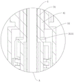
FIG. 9 is an enlarged view taken at A in FIG. 3;
fig. 10 is an enlarged view at B in fig. 3.
In the figure: 1. an inner cutter tube; 2. an outer cutter tube; 3. a first transmission assembly; 4. a second transmission assembly; 5. a housing assembly; 6. an elastic element; 7. a spring seat; 11. an elastic groove; 21. a sampling opening; 22. chopping board surface; 31. a first rotating member; 311. a drive sleeve; 3111. an annular projection; 312. connecting a sleeve; 3121. a sliding groove; 32. a second rotating member; 321. a sliding projection; 41. a first transmission member; 411. rotating the sleeve; 412. a threaded bushing; 4121. a jaw; 4122. an active area; 4123. an internal thread; 42. a second transmission member; 421. an external thread; 422. a guide groove; 51. a first housing; 52. a second housing; 521. a guide projection; 53. the block is indicated.
Detailed Description
The following non-limiting detailed description of the present invention is provided in connection with the preferred embodiments and accompanying drawings. In the description of the present invention, it is to be understood that the terms "center", "longitudinal", "lateral", "length", "width", "thickness", "upper", "lower", "front", "rear", "left", "right", "vertical", "horizontal", "top", "bottom", "inner", "outer", "clockwise", "counterclockwise", "axial", "radial", "circumferential", etc., indicate orientations or positional relationships based on the orientation or positional relationships shown in the drawings. Furthermore, the terms "first", "second" and "first" are used for descriptive purposes only and are not to be construed as indicating or implying relative importance or implicitly indicating the number of technical features indicated. Thus, a feature defined as "first" or "second" may explicitly or implicitly include at least one such feature. In the description of the present invention, "a plurality" means at least two, e.g., two, three, etc., unless specifically limited otherwise. The embodiments described below with reference to the drawings are illustrative and intended to be illustrative of the invention and are not to be construed as limiting the invention.
The invention discloses a constant-force tissue cutting protection system, which comprises an outer cutter tube 2 and an inner cutter tube 1 penetrating through the outer cutter tube 2, wherein a sampling opening 21 is formed in the outer cutter tube 2, and the inner cutter tube 1 reciprocates in the outer cutter tube 2 and rotates for a half cycle (180 degrees) in the reciprocating motion, referring to fig. 1, fig. 2 and fig. 3. The constant force tissue cutting protection system further comprises a first transmission assembly 3, a second transmission assembly 4 and a housing assembly 5, wherein the first transmission assembly 3, the second transmission assembly 4 and the housing assembly 5 are respectively provided with independent driving members (not shown) for driving operation, and the driving members are all in the prior art, so that the detailed description thereof is omitted. One end of the first transmission component 3 is fixedly connected with the inner cutter tube 1, and the other end of the first transmission component is driven by an external driving piece; one end of the second transmission component 4 is connected with the first transmission component 3, and the other end is driven by an external driving part; the housing assembly 5 is connected at one end to the outer cutter tube 2 and at the other end is driven by its external drive.
With further reference to fig. 1, 3, 4 and 9, the first transmission assembly 3 sequentially includes a first rotating member 31 and a second rotating member 32 fixedly connected to the inner cutting tube 1 toward the sampling opening 21, the first rotating member 31 is sleeved on the second rotating member 32, and the second rotating member 32 can slide in the first rotating member 31 along the axial direction of the inner cutting tube 1. Specifically, the first rotating member 31 is in a sleeve shape, the diameter of the first rotating member is distributed in a step shape, and the first rotating member includes a transmission sleeve 311 and a connection sleeve 312, the transmission sleeve 311 is connected with the end of the connection sleeve 312, the transmission sleeve 311 and the connection sleeve 312 are integrally formed, the connection sleeve 312 is disposed near the sampling opening 21, and the diameter of the connection sleeve 312 is larger than that of the transmission sleeve 311. The end of the driving sleeve 311 remote from the connecting sleeve 312 is driven by a gear (not shown) to an external driving member. The drive sleeve 311 has a diameter slightly larger than the diameter of the inner cutter tube 1 and is non-contacting.
On the inner wall of the joint sleeve 312, there are provided sliding grooves 3121 provided in the axial direction thereof, the sliding grooves 3121 being provided in a pair, the pair of sliding grooves 3121 being provided symmetrically with respect to the axis of the joint sleeve 312. The second rotating member 32 is in a sleeve shape, a pair of sliding protrusions 321 corresponding to the sliding grooves 3121 one by one are provided on an outer wall of the second rotating member 32, and the sliding protrusions 321 are located in the corresponding sliding grooves 3121, so that the second rotating member 32 can slide along the axial direction of the first rotating member 31. Wherein, the inner wall of the second rotating part 32 is attached to the outer wall of the inner knife pipe 1, and the second rotating part 32 is adhered to the inner knife pipe 1 by glue, and of course, can be connected together in a buckling manner.
Referring to fig. 2, the movement of the second rotating member 32 can drive the inner knife tube 1 to move, and when the external driving member drives the first rotating member 31 to rotate through the gear, the second rotating member 32 can rotate through the limitation of the sliding groove 3121 and the sliding protrusion 321, and further drive the inner knife tube 1 to rotate. Through to outside driving piece, for example the motor, control its just reversal, can control interior sword pipe 1 pivoted angle, seted up conical elastic groove 11 on interior sword pipe 1 in this scheme, in order to avoid the edge in elastic groove 11 and the edge of sample opening 21 to block each other or rub, the turned angle of interior sword pipe 1 is 180 (half week promptly), and the elastic groove 11 of interior sword pipe 1 is located the below of sample opening 21 all the time in this scheme promptly.
Referring to fig. 5 and 6, the second transmission assembly 4 includes a first transmission member 41 and a second transmission member 42 threadedly coupled to the first transmission member 41, the second transmission member 42 being disposed adjacent to the sampling opening 21. One end of the first transmission member 41 is sleeved on the first transmission member 31 and is in limit fit with the first transmission member 31, and when the first transmission member 41 is in limit fit with the first transmission member 31, the axial relative position of the first transmission member 41 and the first transmission member 31 is limited, but the rotation of the first transmission member 41 relative to the first transmission member 31 in the circumferential direction is not hindered. Referring to fig. 10, one end of the second transmission member 42 is limited in the same manner as the second rotation member 32, the first transmission member 41 is driven by an external driving member, for example, a motor is driven by a gear, the first transmission member 41 drives the second transmission member 42 by a screw thread, the position of the second transmission member 42 in the axial direction is moved forward or backward, and the second rotation member 32 limited and connected to the second transmission member 42 is moved forward or backward, thereby driving the inner cutter tube 1 to move forward or backward. Wherein, the second driving medium 42 is carried out circumferential spacing by shell subassembly 5 for second driving medium 42 only carries out axial and advances or retreat, and does not take place circumferential rotation, makes second driving medium 42 only to second rotation piece 32 transmission axial motion, and then makes the axial of interior tool section 1 and circumferential motion can use different driving piece drives, and its axial and circumferential motion are independent to be opened, thereby is convenient for control the motion of interior tool section 1.
Referring to fig. 4, 6, 7 and 9, the first transmission member 41 comprises a rotating sleeve 411 and a threaded sleeve 412, the threaded sleeve 412 being arranged close to the sampling opening 21. The rotating sleeve 411 is sleeved on the transmission sleeve 311, and is not fixed to the transmission sleeve 311, and the rotating sleeve 411 can rotate freely relative to the transmission sleeve 311. The end of the threaded sleeve 412 close to the rotating sleeve 411 is provided with a pair of claws 4121, an active area 4122 is arranged between the claws 4121 and the end of the rotating sleeve 411, the driving sleeve 311 is further provided with an annular protrusion 3111, the annular protrusion 3111 is installed in the active area 4122, at this time, the top of the claws 4121 abuts against the annular protrusion 3111, and the other end of the annular protrusion 3111 is limited by the top end of the rotating sleeve 411, so that the first transmission member 41 and the first rotating member 31 are limited and connected together through the limitation of the annular protrusion 3111, and the limitation connection mode of the second transmission member 42 and the second rotating member 32 is the same, which will not be described herein again.
Referring to fig. 5 and 6, an inner thread 4123 is provided on an inner wall of the threaded sleeve 412, the second transmission member 42 is partially sleeved on the first transmission member 31, an outer thread 421 is provided on an outer wall of the second transmission member 42, and the first transmission member 41 can drive the second transmission member 42 to move by matching the inner thread 4123 with the outer thread 421.
Referring to fig. 6 and 8, the housing assembly 5 includes a first housing 51, a second housing 52, and an indication block 53 fixedly connected to the outer blade tube 2, and the first housing 51, the second housing 52, and the indication block 53 are snap-connected to each other. In order to allow only axial displacement of the second transmission element 42, but not circumferential rotation. The inner wall of the second housing 52 is provided with a guide protrusion 521, the guide protrusion 521 is long and is parallel to the axis of the inner cutter tube 1, the outer wall of the second transmission member 42 is provided with a guide groove 422 matched with the guide protrusion 521, and the guide groove 422 is arranged on the external thread 421.
Referring to fig. 2, the end of the outer knife tube 2 is further provided with an anvil surface 22, and during operation, the end of the inner knife tube 1 will impact on the anvil surface 22, so that the cut tissue is completely cut, but the impact force at the end of the inner knife tube 1 cannot be too large or too small, the inner knife tube is easy to be cut incompletely if the impact force is too small, and the edge rolling at the end of the inner knife tube 1 is caused if the impact force is too large, so that the force of the end of the inner knife tube 1 impacting on the anvil surface 22 needs to be controlled within a reasonable range.
Referring to fig. 2 and 3, the indication block 53 is adhered to the outer cutter tube 2, the indication block 53 is sequentially provided with an elastic element 6 and a spring seat 7 in the direction of the second rotating member 32, the elastic element 6 and the spring seat 7 are both sleeved on the outer cutter tube 2, and the bottom end of the spring seat 7 abuts against the end of the second rotating member 32. The elastic member 6 is preferably a spring made of stainless steel (SUS 304-WPB); belongs to a cylindrical spiral compression spring, the range of the spring compression amount is 5-16mm, and the range of the force value is 6-26N. Specifically, one end of the elastic element 6 abuts on the indication block 53, and the other end of the elastic element 6 is sleeved and abuts on the spring seat 7. When the inner knife tube 1 moves forwards and moves in a half-circle mode, the elastic element 6 is compressed, and applies reverse acting force to the inner knife tube 1, wherein the maximum stroke provided by the first transmission assembly 3 to the inner knife tube 1 is 22mm, the maximum compression amount of the elastic element 6 is 16mm, at the moment, the maximum acting force provided by the elastic element 6 to the system is 26N, so that the compression amount (16mm) of the spring is fixed at the end of the stroke of the inner knife tube 1, and the acting force value (26N) provided by the spring is fixed, so that the inner knife tube 1 can be ensured to apply fixed acting force to cut off required tissues, and the inner knife tube 1 can be ensured not to be worn and damaged.
Referring to fig. 2 and 3, the indication block 53 is provided with a bump (not shown) for indicating the direction of the sampling opening 21 of the outer cutter tube 2. The housing assembly 5 formed by the indicator block 53, the first housing 51 and the second housing 52 encases both the first transmission assembly 3 and the second transmission assembly 4, wherein the ends of the assembly 5 of the first housing 51 are connected with an external drive through gears. It should be noted that the transmission parts of the first casing 51, the first transmission member 41 and the first rotating member 31 are sequentially exposed in a step shape, so that each component can realize various independent operations.
The above-mentioned embodiments only express several embodiments of the present invention, and the description thereof is more specific and detailed, but not construed as limiting the scope of the present invention. It should be noted that, for a person skilled in the art, several variations and modifications can be made without departing from the inventive concept, which falls within the scope of the present invention. Therefore, the protection scope of the present patent shall be subject to the appended claims.
Claims (9)
Priority Applications (1)
| Application Number | Priority Date | Filing Date | Title |
|---|---|---|---|
| CN202111454085.7A CN114451965A (en) | 2021-12-01 | 2021-12-01 | Constant force tissue cutting protection system |
Applications Claiming Priority (1)
| Application Number | Priority Date | Filing Date | Title |
|---|---|---|---|
| CN202111454085.7A CN114451965A (en) | 2021-12-01 | 2021-12-01 | Constant force tissue cutting protection system |
Publications (1)
| Publication Number | Publication Date |
|---|---|
| CN114451965A true CN114451965A (en) | 2022-05-10 |
Family
ID=81406248
Family Applications (1)
| Application Number | Title | Priority Date | Filing Date |
|---|---|---|---|
| CN202111454085.7A Pending CN114451965A (en) | 2021-12-01 | 2021-12-01 | Constant force tissue cutting protection system |
Country Status (1)
| Country | Link |
|---|---|
| CN (1) | CN114451965A (en) |
Cited By (3)
| Publication number | Priority date | Publication date | Assignee | Title |
|---|---|---|---|---|
| CN116158791A (en) * | 2023-03-17 | 2023-05-26 | 重庆西山科技股份有限公司 | Biopsy needle convenient for retracting knife |
| CN116831643A (en) * | 2023-08-10 | 2023-10-03 | 湖南峰恒晶医疗科技有限公司 | A closed continuous sampling breast biopsy needle |
| WO2025055825A1 (en) * | 2023-09-12 | 2025-03-20 | 上海导向医疗系统有限公司 | Biopsy apparatus |
Citations (6)
| Publication number | Priority date | Publication date | Assignee | Title |
|---|---|---|---|---|
| US20040167428A1 (en) * | 2003-02-24 | 2004-08-26 | Senorx, Inc. | Biopsy device with inner cutting member |
| US20050065453A1 (en) * | 2003-02-24 | 2005-03-24 | Senorx, Inc. | Biopsy device with selectable tissue receiving aperture orientation and site illumination |
| US20060276723A1 (en) * | 2005-05-23 | 2006-12-07 | Senorx, Inc. | Tissue cutting member for a biopsy device |
| CN109820542A (en) * | 2019-02-01 | 2019-05-31 | 何定甫 | Breast biopsy sample probe |
| CN210931554U (en) * | 2019-09-30 | 2020-07-07 | 深圳成川医疗有限公司 | Cutter assembly and rotary cutting system |
| CN217040240U (en) * | 2021-12-01 | 2022-07-26 | 利福昇(苏州)医疗科技有限公司 | Constant force tissue cutting protection system |
-
2021
- 2021-12-01 CN CN202111454085.7A patent/CN114451965A/en active Pending
Patent Citations (6)
| Publication number | Priority date | Publication date | Assignee | Title |
|---|---|---|---|---|
| US20040167428A1 (en) * | 2003-02-24 | 2004-08-26 | Senorx, Inc. | Biopsy device with inner cutting member |
| US20050065453A1 (en) * | 2003-02-24 | 2005-03-24 | Senorx, Inc. | Biopsy device with selectable tissue receiving aperture orientation and site illumination |
| US20060276723A1 (en) * | 2005-05-23 | 2006-12-07 | Senorx, Inc. | Tissue cutting member for a biopsy device |
| CN109820542A (en) * | 2019-02-01 | 2019-05-31 | 何定甫 | Breast biopsy sample probe |
| CN210931554U (en) * | 2019-09-30 | 2020-07-07 | 深圳成川医疗有限公司 | Cutter assembly and rotary cutting system |
| CN217040240U (en) * | 2021-12-01 | 2022-07-26 | 利福昇(苏州)医疗科技有限公司 | Constant force tissue cutting protection system |
Cited By (3)
| Publication number | Priority date | Publication date | Assignee | Title |
|---|---|---|---|---|
| CN116158791A (en) * | 2023-03-17 | 2023-05-26 | 重庆西山科技股份有限公司 | Biopsy needle convenient for retracting knife |
| CN116831643A (en) * | 2023-08-10 | 2023-10-03 | 湖南峰恒晶医疗科技有限公司 | A closed continuous sampling breast biopsy needle |
| WO2025055825A1 (en) * | 2023-09-12 | 2025-03-20 | 上海导向医疗系统有限公司 | Biopsy apparatus |
Similar Documents
| Publication | Publication Date | Title |
|---|---|---|
| CN114451965A (en) | Constant force tissue cutting protection system | |
| US11779316B2 (en) | Biopsy device | |
| US20060149163A1 (en) | Core sampling biopsy device with short coupled MRI-compatible driver | |
| WO1989002250A1 (en) | Tubular microsurgery cutting apparatus | |
| WO1981001363A1 (en) | Co-axial tube surgical infusion/suction cutter tip | |
| US9982763B2 (en) | Electrically powered drive system for medical device | |
| WO2017092578A1 (en) | Laterally bendable grinding knife for medical use | |
| CN217040240U (en) | Constant force tissue cutting protection system | |
| CN117562627B (en) | Rotary cutting surgical knife | |
| CN113303864B (en) | Elbow pipe grinding tool with angle-adjustable tool bit | |
| CN106725746B (en) | medical cutting device | |
| CN219397468U (en) | Ultrasonic surgical instrument and ultrasonic knife system | |
| CN210931554U (en) | Cutter assembly and rotary cutting system | |
| CN211550425U (en) | Power transmission structure of grinding cutter and grinding cutter | |
| CN210095840U (en) | Grinding tools with adjustable head angle | |
| CN119055320A (en) | Tissue removal device handle, removal device and removal system | |
| CN206852646U (en) | medical cutting device | |
| CN114601532B (en) | Tissue resectoscope and resectioning system | |
| CN115363685A (en) | A medical high-speed grinding drill with a coaxial rotating telescopic structure | |
| CN114469198A (en) | Breast linear cutting biopsy system | |
| CN221671873U (en) | A simple gynecological surgical planer | |
| CN109176258A (en) | A kind of electric mill | |
| CN119837594B (en) | Endoscope operation planing device | |
| CN221357032U (en) | Adjustment device for clamping mechanism | |
| CN213606667U (en) | Elbow pipe grinding tool with angle-adjustable tool bit and turning control mechanism thereof |
Legal Events
| Date | Code | Title | Description |
|---|---|---|---|
| PB01 | Publication | ||
| PB01 | Publication | ||
| SE01 | Entry into force of request for substantive examination | ||
| SE01 | Entry into force of request for substantive examination | ||
| RJ01 | Rejection of invention patent application after publication |
Application publication date: 20220510 |
|
| RJ01 | Rejection of invention patent application after publication |