CN114446696A - Key structure - Google Patents
Key structure Download PDFInfo
- Publication number
- CN114446696A CN114446696A CN202210067597.6A CN202210067597A CN114446696A CN 114446696 A CN114446696 A CN 114446696A CN 202210067597 A CN202210067597 A CN 202210067597A CN 114446696 A CN114446696 A CN 114446696A
- Authority
- CN
- China
- Prior art keywords
- magnetic action
- magnetic
- base
- action piece
- key structure
- Prior art date
- Legal status (The legal status is an assumption and is not a legal conclusion. Google has not performed a legal analysis and makes no representation as to the accuracy of the status listed.)
- Granted
Links
- 230000005291 magnetic effect Effects 0.000 claims abstract description 342
- 230000009471 action Effects 0.000 claims abstract description 234
- 230000003287 optical effect Effects 0.000 claims description 19
- 230000008859 change Effects 0.000 claims description 12
- 230000000903 blocking effect Effects 0.000 claims description 9
- 230000002093 peripheral effect Effects 0.000 claims description 4
- 238000006073 displacement reaction Methods 0.000 claims description 3
- 238000003780 insertion Methods 0.000 claims description 3
- 230000037431 insertion Effects 0.000 claims description 3
- 230000004308 accommodation Effects 0.000 claims description 2
- 238000000034 method Methods 0.000 description 6
- 230000008569 process Effects 0.000 description 5
- 230000006835 compression Effects 0.000 description 4
- 238000007906 compression Methods 0.000 description 4
- 230000008713 feedback mechanism Effects 0.000 description 3
- 230000007246 mechanism Effects 0.000 description 3
- 239000012528 membrane Substances 0.000 description 3
- 238000000926 separation method Methods 0.000 description 3
- XEEYBQQBJWHFJM-UHFFFAOYSA-N Iron Chemical compound [Fe] XEEYBQQBJWHFJM-UHFFFAOYSA-N 0.000 description 2
- 230000004048 modification Effects 0.000 description 2
- 238000012986 modification Methods 0.000 description 2
- 230000035515 penetration Effects 0.000 description 2
- 239000007787 solid Substances 0.000 description 2
- 238000010586 diagram Methods 0.000 description 1
- 230000000694 effects Effects 0.000 description 1
- 239000003302 ferromagnetic material Substances 0.000 description 1
- 229910052742 iron Inorganic materials 0.000 description 1
- 238000003466 welding Methods 0.000 description 1
Images


Classifications
-
- G—PHYSICS
- G06—COMPUTING; CALCULATING OR COUNTING
- G06F—ELECTRIC DIGITAL DATA PROCESSING
- G06F3/00—Input arrangements for transferring data to be processed into a form capable of being handled by the computer; Output arrangements for transferring data from processing unit to output unit, e.g. interface arrangements
- G06F3/01—Input arrangements or combined input and output arrangements for interaction between user and computer
- G06F3/016—Input arrangements with force or tactile feedback as computer generated output to the user
-
- H—ELECTRICITY
- H01—ELECTRIC ELEMENTS
- H01H—ELECTRIC SWITCHES; RELAYS; SELECTORS; EMERGENCY PROTECTIVE DEVICES
- H01H13/00—Switches having rectilinearly-movable operating part or parts adapted for pushing or pulling in one direction only, e.g. push-button switch
- H01H13/70—Switches having rectilinearly-movable operating part or parts adapted for pushing or pulling in one direction only, e.g. push-button switch having a plurality of operating members associated with different sets of contacts, e.g. keyboard
- H01H13/84—Switches having rectilinearly-movable operating part or parts adapted for pushing or pulling in one direction only, e.g. push-button switch having a plurality of operating members associated with different sets of contacts, e.g. keyboard characterised by ergonomic functions, e.g. for miniature keyboards; characterised by operational sensory functions, e.g. sound feedback
- H01H13/85—Switches having rectilinearly-movable operating part or parts adapted for pushing or pulling in one direction only, e.g. push-button switch having a plurality of operating members associated with different sets of contacts, e.g. keyboard characterised by ergonomic functions, e.g. for miniature keyboards; characterised by operational sensory functions, e.g. sound feedback characterised by tactile feedback features
-
- H—ELECTRICITY
- H01—ELECTRIC ELEMENTS
- H01H—ELECTRIC SWITCHES; RELAYS; SELECTORS; EMERGENCY PROTECTIVE DEVICES
- H01H13/00—Switches having rectilinearly-movable operating part or parts adapted for pushing or pulling in one direction only, e.g. push-button switch
- H01H13/02—Details
- H01H13/12—Movable parts; Contacts mounted thereon
- H01H13/14—Operating parts, e.g. push-button
-
- H—ELECTRICITY
- H01—ELECTRIC ELEMENTS
- H01H—ELECTRIC SWITCHES; RELAYS; SELECTORS; EMERGENCY PROTECTIVE DEVICES
- H01H13/00—Switches having rectilinearly-movable operating part or parts adapted for pushing or pulling in one direction only, e.g. push-button switch
- H01H13/02—Details
- H01H13/12—Movable parts; Contacts mounted thereon
- H01H13/20—Driving mechanisms
-
- H—ELECTRICITY
- H01—ELECTRIC ELEMENTS
- H01H—ELECTRIC SWITCHES; RELAYS; SELECTORS; EMERGENCY PROTECTIVE DEVICES
- H01H13/00—Switches having rectilinearly-movable operating part or parts adapted for pushing or pulling in one direction only, e.g. push-button switch
- H01H13/70—Switches having rectilinearly-movable operating part or parts adapted for pushing or pulling in one direction only, e.g. push-button switch having a plurality of operating members associated with different sets of contacts, e.g. keyboard
- H01H13/702—Switches having rectilinearly-movable operating part or parts adapted for pushing or pulling in one direction only, e.g. push-button switch having a plurality of operating members associated with different sets of contacts, e.g. keyboard with contacts carried by or formed from layers in a multilayer structure, e.g. membrane switches
- H01H13/705—Switches having rectilinearly-movable operating part or parts adapted for pushing or pulling in one direction only, e.g. push-button switch having a plurality of operating members associated with different sets of contacts, e.g. keyboard with contacts carried by or formed from layers in a multilayer structure, e.g. membrane switches characterised by construction, mounting or arrangement of operating parts, e.g. push-buttons or keys
-
- G—PHYSICS
- G06—COMPUTING; CALCULATING OR COUNTING
- G06F—ELECTRIC DIGITAL DATA PROCESSING
- G06F3/00—Input arrangements for transferring data to be processed into a form capable of being handled by the computer; Output arrangements for transferring data from processing unit to output unit, e.g. interface arrangements
- G06F3/01—Input arrangements or combined input and output arrangements for interaction between user and computer
- G06F3/02—Input arrangements using manually operated switches, e.g. using keyboards or dials
- G06F3/0202—Constructional details or processes of manufacture of the input device
-
- G—PHYSICS
- G06—COMPUTING; CALCULATING OR COUNTING
- G06F—ELECTRIC DIGITAL DATA PROCESSING
- G06F3/00—Input arrangements for transferring data to be processed into a form capable of being handled by the computer; Output arrangements for transferring data from processing unit to output unit, e.g. interface arrangements
- G06F3/01—Input arrangements or combined input and output arrangements for interaction between user and computer
- G06F3/03—Arrangements for converting the position or the displacement of a member into a coded form
- G06F3/033—Pointing devices displaced or positioned by the user, e.g. mice, trackballs, pens or joysticks; Accessories therefor
- G06F3/0354—Pointing devices displaced or positioned by the user, e.g. mice, trackballs, pens or joysticks; Accessories therefor with detection of 2D relative movements between the device, or an operating part thereof, and a plane or surface, e.g. 2D mice, trackballs, pens or pucks
- G06F3/03543—Mice or pucks
-
- H—ELECTRICITY
- H01—ELECTRIC ELEMENTS
- H01H—ELECTRIC SWITCHES; RELAYS; SELECTORS; EMERGENCY PROTECTIVE DEVICES
- H01H2215/00—Tactile feedback
-
- H—ELECTRICITY
- H01—ELECTRIC ELEMENTS
- H01H—ELECTRIC SWITCHES; RELAYS; SELECTORS; EMERGENCY PROTECTIVE DEVICES
- H01H2221/00—Actuators
- H01H2221/036—Return force
- H01H2221/04—Return force magnetic
Landscapes
- Engineering & Computer Science (AREA)
- General Engineering & Computer Science (AREA)
- Theoretical Computer Science (AREA)
- Human Computer Interaction (AREA)
- Physics & Mathematics (AREA)
- General Physics & Mathematics (AREA)
- Push-Button Switches (AREA)
- Input From Keyboards Or The Like (AREA)
- Percussion Or Vibration Massage (AREA)
- Chair Legs, Seat Parts, And Backrests (AREA)
- Headphones And Earphones (AREA)
Abstract
本发明公开一种按键结构,包含基座、按键板、第一磁作用件以及第二磁作用件。基座内部具有容置空间,且基座的上表面设置连接部。按键板具有按压端、复位端与枢接部;枢接部位于按压端与复位端之间,且枢接部枢接于连接部。第一磁作用件设置于复位端;第二磁作用件设置于基座,并且第二磁作用件相应于第一磁作用件配置。按键结构是配置为第一磁作用件与第二磁作用件以磁力互相吸引或排斥,而提供或增减按压端的按压阻力。

The invention discloses a key structure, comprising a base, a key board, a first magnetic action piece and a second magnetic action piece. The interior of the base has an accommodating space, and the upper surface of the base is provided with a connecting portion. The key board has a pressing end, a reset end and a pivot part; the pivot part is located between the pressing end and the reset end, and the pivot part is pivotally connected to the connection part. The first magnetic action piece is arranged on the reset end; the second magnetic action piece is arranged on the base, and the second magnetic action piece is arranged corresponding to the first magnetic action piece. The key structure is configured such that the first magnetic action piece and the second magnetic action piece attract or repel each other by magnetic force, so as to provide or increase or decrease the pressing resistance of the pressing end.
Description
技术领域technical field
本发明涉及按键,具体而言,本发明关于一种通过成对磁作用件的配置提供按压反馈手感的按键结构。The present invention relates to keys, and in particular, the present invention relates to a key structure that provides a pressing feedback feel through the configuration of pairs of magnetic action members.
背景技术Background technique
按键结构通常包含触发开关与设置于触发开关上方的按压件(例如按键板或按键帽);常见的触发开关有机械式微动开关、薄膜开关与光开关。机械式微动开关的触发点有明确的按压阻力,让使用者感受到按压反馈手感。薄膜开关的按压反馈手感较小。The key structure usually includes a trigger switch and a pressing member (such as a key board or a key cap) disposed above the trigger switch; common trigger switches include mechanical micro switches, membrane switches and optical switches. The trigger point of the mechanical micro switch has a clear pressing resistance, allowing the user to feel the pressing feedback feel. Membrane switches have less press feedback feel.
机械式微动开关与薄膜开关在使用过程中会持续受到磨损,而使得其寿命较短。光开关被触发的过程中,光开关内部不会有可动件或变形件作动,而可有效避免磨损。然而,光开关本身无法提供任何反馈手感。Mechanical microswitches and membrane switches are subject to continuous wear and tear during use, resulting in shorter lifespans. During the triggering process of the optical switch, there will be no movable parts or deformable parts inside the optical switch to act, which can effectively avoid wear and tear. However, the optical switch itself cannot provide any feedback feel.
发明内容SUMMARY OF THE INVENTION
鉴于现有技术中的问题,本发明提供一种按键结构以解决上述问题。In view of the problems in the prior art, the present invention provides a key structure to solve the above problems.
因此,本发明所要解决的技术问题在于提供一种按键结构,该按键结构包含:Therefore, the technical problem to be solved by the present invention is to provide a key structure, and the key structure includes:
基座,该基座具有上表面;a base having an upper surface;
按键板,该按键板具有按压端、复位端与枢接部;该基座与该按键板彼此枢接相连;a key board, the key board has a pressing end, a reset end and a pivot part; the base and the key board are pivotally connected to each other;
第一磁作用件,其设置于该复位端;以及a first magnetic action member, which is disposed at the reset end; and
第二磁作用件,其设置于该基座,并且该第二磁作用件相对应于该第一磁作用件配置;其中该第一磁作用件与该第二磁作用件以磁力互相吸引或排斥,而提供或增减该按压端的按压阻力。The second magnetic action piece is disposed on the base, and the second magnetic action piece is disposed corresponding to the first magnetic action piece; wherein the first magnetic action piece and the second magnetic action piece attract each other by magnetic force or Repel, and provide or increase or decrease the pressing resistance of the pressing end.
作为可选的技术方案,该第一磁作用件与该第二磁作用件是导磁元件与磁铁的组合。As an optional technical solution, the first magnetic action member and the second magnetic action member are a combination of a magnetic conducting element and a magnet.
作为可选的技术方案,该第一磁作用件与该第二磁作用件分别为磁铁,并且该第一磁作用件以及该第二磁作用件之间以相同或不同磁极互相面对。As an optional technical solution, the first magnetic action piece and the second magnetic action piece are respectively magnets, and the first magnetic action piece and the second magnetic action piece face each other with the same or different magnetic poles.
作为可选的技术方案,该上表面设置有凹槽,该第二磁作用件设置于该凹槽;该复位端设置有凸柱,该凸柱延伸进入该凹槽中,并且该第一磁作用件设置于该凸柱的前端。As an optional technical solution, the upper surface is provided with a groove, the second magnetic action member is provided in the groove; the reset end is provided with a protruding post, the protruding post extends into the groove, and the first magnetic The action piece is arranged at the front end of the protruding post.
作为可选的技术方案,该凸柱包含第一侧面,该凹槽包含第二侧面,该第一侧面与该按键板的表面之间具有凸柱夹角,该第二侧面与该基座表面之间也具有对应于该凸柱夹角的凹槽夹角。As an optional technical solution, the protruding post includes a first side surface, the groove includes a second side surface, the first side surface and the surface of the key board have an included angle of the protruding post, and the second side surface and the base surface There is also an included angle of the groove corresponding to the included angle of the protruding post.
作为可选的技术方案,该枢接部位于该按压端与该复位端之间,该复位端的该第一磁作用件与该第二磁作用件以磁力互相吸引。As an optional technical solution, the pivot portion is located between the pressing end and the reset end, and the first magnetic action piece and the second magnetic action piece of the reset end attract each other by magnetic force.
作为可选的技术方案,该复位端位于该按压端与该该枢接部之间,或者该按压端位于该复位端与该枢接部之间,该复位端的该第一磁作用件与该第二磁作用件以磁力互相排斥。As an optional technical solution, the reset end is located between the pressing end and the pivot portion, or the pressing end is located between the reset end and the pivot portion, and the first magnetic action member of the reset end is connected to the The second magnetically acting members repel each other by magnetic force.
作为可选的技术方案,该第一磁作用件位于该按键板朝向该基座的一面,且该第二磁作用件嵌于该上表面。As an optional technical solution, the first magnetic action piece is located on the side of the key board facing the base, and the second magnetic action piece is embedded in the upper surface.
作为可选的技术方案,该基座的内部具有容置空间,该第一磁作用件位于该按键板朝向该基座的一面,且该第二磁作用件嵌于该容置空间的内壁面。As an optional technical solution, the interior of the base has an accommodating space, the first magnetic effect member is located on the side of the key board facing the base, and the second magnetic effect member is embedded in the inner wall surface of the accommodating space .
作为可选的技术方案,该基座的内部具有容置空间,该上表面设置有穿孔,该穿孔连通该容置空间;该按压端设置有挡片,该挡片过该穿孔而延伸进入该容置空间。As an optional technical solution, the interior of the base has an accommodating space, the upper surface is provided with a perforation, and the perforation communicates with the accommodating space; the pressing end is provided with a blocking piece, and the blocking piece passes through the perforation and extends into the accommodation space.
作为可选的技术方案,该按键结构还包含:As an optional technical solution, the key structure also includes:
电路板,该电路板固定于基座并且位于该容置空间中;以及a circuit board fixed to the base and located in the accommodating space; and
光开关,该光开关设置于该电路板上;当该按压端被向下按压,且该第一磁作用件脱离该第二磁作用件时,该挡片插入该光开关而触发该光开关产生相应的触发信号。an optical switch, the optical switch is arranged on the circuit board; when the pressing end is pressed down and the first magnetic action piece is separated from the second magnetic action piece, the blocking plate is inserted into the light switch to trigger the light switch Generate the corresponding trigger signal.
作为可选的技术方案,该按键结构还包含固定件以及悬臂,该固定件固定于该上壳体,该基座的内部具有容置空间,并且该固定件至少局部位于该容置空间中,该悬臂位于该容置空间中,该悬臂的一端固定于该固定件,并且第二磁作用件固定于该悬臂的另一端;As an optional technical solution, the button structure further includes a fixing member and a cantilever, the fixing member is fixed on the upper casing, the interior of the base has an accommodating space, and the fixing member is at least partially located in the accommodating space, The cantilever is located in the accommodating space, one end of the cantilever is fixed to the fixing member, and the second magnetic action member is fixed to the other end of the cantilever;
其中,该上表面开设有开孔,该开孔相对应于该第一磁作用件,并且该第二磁作用件穿过该开孔。Wherein, the upper surface is provided with an opening, the opening corresponds to the first magnetic action member, and the second magnetic action member passes through the opening.
作为可选的技术方案,该按键结构还包含调整元件,该调整元件可转动地或可移动地设置于该基座,且该第二磁作用件设置于该调整元件,通过该调整元件的转动或移动改变该第一磁作用件与该第二磁作用件之间的间隔距离。As an optional technical solution, the key structure further includes an adjustment element, the adjustment element is rotatably or movably arranged on the base, and the second magnetic action member is arranged on the adjustment element, and through the rotation of the adjustment element Or move to change the spacing distance between the first magnetic action piece and the second magnetic action piece.
作为可选的技术方案,该基座的内部具有容置空间,该调整元件是移动件,该移动件可移动地设置于该基座,并且至少局部位于该容置空间中;As an optional technical solution, an accommodating space is provided inside the base, and the adjusting element is a moving piece, and the moving piece is movably arranged on the base and at least partially located in the accommodating space;
其中,该上表面开设有开孔,该复位端设置有凸柱,该凸柱穿过该开孔,并且该第二磁作用件设置于该移动件;该移动件用以相对于该基座位移,从而改变该第一磁作用件与该第二磁作用件之间的间隔距离。Wherein, the upper surface is provided with an opening, the reset end is provided with a protruding post, the protruding post passes through the opening, and the second magnetic action member is disposed on the moving member; the moving member is used for relative to the base displacement, thereby changing the spacing distance between the first magnetic action piece and the second magnetic action piece.
作为可选的技术方案,该上表面开设滑动孔,该移动件穿过该滑动孔。As an optional technical solution, a sliding hole is defined on the upper surface, and the moving member passes through the sliding hole.
作为可选的技术方案,该移动件设置多个定位块,且该滑动孔中设置定位嵌槽,该多个定位块可选择地嵌入该定位嵌槽。As an optional technical solution, the moving member is provided with a plurality of positioning blocks, and the sliding hole is provided with a positioning insert groove, and the plurality of positioning blocks can be selectively embedded in the positioning insert groove.
作为可选的技术方案,该调整元件包含:As an optional technical solution, the adjustment element includes:
轴杆,可转动地设置于该基座;以及a shaft rod rotatably disposed on the base; and
转盘,设置于该轴杆并且位于该容置空间中;a turntable, arranged on the shaft and located in the accommodating space;
其中,该第二磁作用件设于该转盘的外周面。Wherein, the second magnetic action member is arranged on the outer peripheral surface of the turntable.
作为可选的技术方案,该调整元件为轴杆,并且该第二磁作用件设置于该轴杆上,且该第二磁作用件是偏心设置的转动元件,该第二磁作用件用以随同该轴杆转动,而改变该第二磁作用件与第一磁作用件之间的最小间隔距离。As an optional technical solution, the adjustment element is a shaft rod, and the second magnetic action piece is arranged on the shaft rod, and the second magnetic action piece is an eccentrically arranged rotating element, and the second magnetic action piece is used for Along with the rotation of the shaft, the minimum separation distance between the second magnetic action piece and the first magnetic action piece is changed.
作为可选的技术方案,该调整元件包含:As an optional technical solution, the adjustment element includes:
轴杆,可转动地设置于该基座;a shaft rod, which is rotatably arranged on the base;
两个导引盘,设置于该轴杆上,并且该两个导引盘上分别设置相对应的螺旋线槽;以及two guide plates, which are arranged on the shaft rod, and are respectively provided with corresponding helical grooves on the two guide plates; and
导引座,其相对的两个侧面分别设置有导引杆,各导引杆分别可滑动地插入相对应的螺旋线槽,并且该第二磁作用件设置于该导引座上;其中,随着该轴杆转动,各导引杆滑动于相对应的螺旋线槽中,而改变该第二磁作用件与该第一磁作用件之间的间隔距离。The guide base, two opposite sides of which are respectively provided with guide rods, each guide rod is respectively slidably inserted into the corresponding helical groove, and the second magnetic action member is arranged on the guide base; wherein, As the shaft rotates, each guide rod slides into the corresponding helical groove, thereby changing the distance between the second magnetic action piece and the first magnetic action piece.
作为可选的技术方案,该按键结构具有相同的多个第二磁作用件,该多个第二磁作用件被区分为多个群组,该多个群组分别设置于调整元件上的不同位置,并且各群组具有的第二磁作用件的数量不同。As an optional technical solution, the key structure has a plurality of the same second magnetic action members, the plurality of second magnetic action members are divided into a plurality of groups, and the plurality of groups are respectively arranged on different positions on the adjustment element. position, and each group has a different number of second magnetic action members.
作为可选的技术方案,该按键结构具有不同的多个第二磁作用件,该多个第二磁作用件分别设置于该调整元件上的不同位置。As an optional technical solution, the key structure has a plurality of different second magnetic action members, and the plurality of second magnetic action members are respectively arranged at different positions on the adjustment element.
作为可选的技术方案,其特征在于:As an optional technical solution, it is characterized in that:
该上表面上凹设有内凹部,且该内凹部通过穿置孔连通该容置空间,并且该内凹部与该容置空间的连接处设置轴座;以及A concave portion is concave on the upper surface, and the concave portion communicates with the accommodating space through a through hole, and a shaft seat is provided at the connection between the concave portion and the accommodating space; and
该轴杆具有穿置端、转柄以及凸缘部;该轴杆穿过该穿置孔,该穿置端位于该容置空间中,该转柄位于该内凹部,并且该凸缘部位于该穿置端与该转柄之间并且嵌入该轴座。The shaft has a through end, a handle and a flange; the shaft passes through the through hole, the through end is located in the accommodating space, the handle is located in the concave part, and the flange is located in the accommodating space The shaft seat is embedded between the insertion end and the turning handle.
以下结合附图和具体实施例对本发明进行详细描述,但不作为对本发明的限定。The present invention is described in detail below with reference to the accompanying drawings and specific embodiments, but is not intended to limit the present invention.
附图说明Description of drawings
图1是本发明第一实施例中,按键结构的外观立体示意图。FIG. 1 is a three-dimensional schematic diagram of the appearance of the key structure in the first embodiment of the present invention.
图2是本发明第一实施例中,按键结构的剖视图。FIG. 2 is a cross-sectional view of the key structure in the first embodiment of the present invention.
图3与图4是本发明第一实施例中,按键结构的局部放大剖视图。3 and 4 are partial enlarged cross-sectional views of the key structure in the first embodiment of the present invention.
图5与图6是本发明第一实施例中,另一实施方式的按键结构的局部放大剖视图。5 and 6 are partial enlarged cross-sectional views of the key structure of another embodiment in the first embodiment of the present invention.
图7与图8是本发明第二实施例中,按键结构的局部放大剖视图。7 and 8 are partial enlarged cross-sectional views of the key structure in the second embodiment of the present invention.
图9是本发明第三实施例中,按键结构的剖视图。9 is a cross-sectional view of a key structure in a third embodiment of the present invention.
图10是本发明第三实施例中,按键结构的局部放大剖视图。10 is a partial enlarged cross-sectional view of the key structure in the third embodiment of the present invention.
图11是本发明第四实施例中,按键结构的局部放大剖视图。11 is a partial enlarged cross-sectional view of the key structure in the fourth embodiment of the present invention.
图12是本发明第五实施例中,按键结构的局部放大剖视图。12 is a partial enlarged cross-sectional view of the key structure in the fifth embodiment of the present invention.
图13是本发明第六实施例中,调整元件、第一磁作用件与第二磁作用件的外观立体示意图。13 is a perspective view of the appearance of the adjusting element, the first magnetic action member and the second magnetic action member in the sixth embodiment of the present invention.
图14是本发明第六实施例中,按键结构的局部放大剖视图。14 is a partial enlarged cross-sectional view of the key structure in the sixth embodiment of the present invention.
图15与图16是本发明第六实施例中,调整元件、第一磁作用件与第二磁作用件的正视图。15 and 16 are front views of the adjusting element, the first magnetic action member and the second magnetic action member in the sixth embodiment of the present invention.
图17与图18是本发明不同实施例中,调整元件、第一磁作用件与第二磁作用件的正视图。17 and 18 are front views of the adjustment element, the first magnetic action member and the second magnetic action member in different embodiments of the present invention.
图19与图20是本发明不同实施例中,按键结构的局部放大剖视图。19 and FIG. 20 are partial enlarged cross-sectional views of key structures in different embodiments of the present invention.
图21是本发明第七实施例中,调整元件、第一磁作用件与第二磁作用件的侧视图。21 is a side view of the adjusting element, the first magnetic action member and the second magnetic action member in the seventh embodiment of the present invention.
图22与图23是本发明不同实施例中,调整元件、第一磁作用件与第二磁作用件的正视图。22 and 23 are front views of the adjusting element, the first magnetic action member and the second magnetic action member in different embodiments of the present invention.
图24是本发明第八实施例中,按键结构的局部放大剖视图。24 is a partial enlarged cross-sectional view of the key structure in the eighth embodiment of the present invention.
图25与图26是本发明不同实施例中,调整元件、第一磁作用件与第二磁作用件的正视图。25 and 26 are front views of the adjusting element, the first magnetic action member and the second magnetic action member in different embodiments of the present invention.
具体实施方式Detailed ways
为使对本发明的目的、构造、特征、及其功能有进一步的了解,兹配合实施例详细说明如下。本发明各实施例的发明思路需要考虑以下基本限制、解决相关问题:(1)按键若要达成手感反馈,直观上需另外设置反馈机构实体连接按压件,以在使用过程中提供适当的反馈手感;(2)前述反馈机构不仅增加按键结构的复杂度,同时反馈机构由于采取实体连接,本身也是容易因为反复操作而受到磨损的零组件;(3)采用光开关按键时,如果按键没有其他弹性件提供复位力量,本发明实施例须能提供按压阻力作为手感反馈;(4)按压阻力可以进一步切换改变,使同一按键还可以提供不同的手感。In order to have a further understanding of the purpose, structure, features, and functions of the present invention, the following detailed descriptions are given in conjunction with the embodiments. The inventive idea of each embodiment of the present invention needs to consider the following basic limitations and solve related problems: (1) If the button wants to achieve feel feedback, it is intuitively necessary to additionally set a feedback mechanism to physically connect the pressing piece, so as to provide an appropriate feedback feel during use. ; (2) The aforementioned feedback mechanism not only increases the complexity of the button structure, but also the feedback mechanism itself is a component that is easily worn due to repeated operations due to its physical connection; (3) When using the optical switch button, if the button has no other elasticity (4) The pressing resistance can be further switched and changed, so that the same button can also provide different feel.
请参阅图1与图2所示,为本发明第一实施例所公开的一种按键结构,应用于需要配置按键的电子装置。所述电子装置可为但不限于鼠标、轨迹球等输入装置。按键结构1包含基座130、按键板140、第一磁作用件110以及第二磁作用件120。Please refer to FIG. 1 and FIG. 2 , which are a key structure disclosed in the first embodiment of the present invention, which is applied to an electronic device that needs to configure keys. The electronic device may be, but not limited to, an input device such as a mouse, a trackball, and the like. The
如图1与图2所示,基座130可为前述电子装置的壳体,并且基座130包含上壳体132以及下壳体134。上壳体132结合于下壳体134而形成定义于基座130内部的容置空间136。上壳体132的外表面,亦即,基座130的上表面130a设置连接部138。As shown in FIG. 1 and FIG. 2 , the base 130 can be the casing of the aforementioned electronic device, and the
如图1与图2所示,按键板140具有按压端142、复位端144以及枢接部146。按键板140可为平直板件,也可以是具有曲面轮廓而配合基座130的上表面130a。枢接部146位于按压端142与复位端144之间,并且枢接于连接部138,使得按压端142与复位端144可以互为反向地在上表面130a上下移动,亦即按键板140可基于连接部138前后摆动。As shown in FIGS. 1 and 2 , the
本发明下述各实施例的枢接部146并不需要限制位于按压端142与复位端144之间。在不同实施例中,如图5以及图6所示,在第一磁作用件110与第二磁作用件120以磁力相互排斥的实施例中,复位端144也可以位于按压端142与枢接部146之间,或者按压端142也可以位于复位端144与枢接部146之间。实际操作中,依照需要,第一磁作用件110与第二磁作用件120可以调整为以磁力互相吸引或排斥(图1、图2、图3以及图4中示出的是第一磁作用件与第二磁作用件以磁力相互吸引的实施例,图5以及图6中示出的是第一磁作用件与第二磁作用件以磁力相互排斥的实施例),来搭配枢接部146,按压端142与复位端144三者的相对位置,以便通过改变按压端的按压阻力来形成按压手感的反馈变化。The
如图1至图6所示,第一磁作用件110以及第二磁作用件120之间以磁力互相吸引或排斥。第一磁作用件110设置于按键板140的复位端144,第二磁作用件120设置于基座130,并且第二磁作用件120相应于第一磁作用件110设置。第一磁作用件110与第二磁作用件120以磁力互相吸引或排斥,以便提供、增加或减少按压阻力的效果,也就是说,第一磁作用件110与第二磁作用120之间的作用力可用于单独提供按压阻力(当无其他回复机构时),或者用于辅助增加按压阻力(当具有其他回复机构时),或者用于辅助减少按压阻力(当具有其他回复机构时)。也使得复位端144因磁力而朝向上表面130a接近(或远离),而按压端142因磁力而远离上表面130a(或接近)。在不同实施例中,按键结构1设置有其他弹性件(如扭簧、板簧、压簧等)抵靠于按键板140与基座130之间来提供基本按压阻力,那么第一磁作用件110以及第二磁作用件120的相互吸引或排斥的磁力,可供增加或减少按压阻力。当第一磁作用件110以及第二磁作用件120之间的磁力是按键结构1唯一的复位力量时,此磁力是直接提供为按键结构1唯一的按压阻力。As shown in FIG. 1 to FIG. 6 , the first
如图3所示,具体而言,第一磁作用件110与第二磁作用件120以磁力互相吸引的状态包含至少两种具体实施例。在第一种具体实施例中,第一磁作用件110以磁力结合于第二磁作用件120,使得作用于第一磁作用件110的磁力为可到达的最大值。在第二种具体实施例中,受到基座130的上表面130a对复位端144的限位,第一磁作用件110与第二磁作用件120之间保持结构允许的最小间隔距离,而维持小于最大磁力的磁力值。As shown in FIG. 3 , specifically, the state in which the first
如图3与图4所示,当按压端142持续受压,例如使用者以手指对按压端142施压,通过力臂作用使得复位端144对第一磁作用件110施加脱离第二磁作用件120的拉力。所述拉力逐渐上升,而大于第一磁作用件110以及第二磁作用件120之间的磁力值时,第一磁作用件110将瞬间快速远离第二磁作用件120,而使得按压端142可瞬间跳脱快速向下移动。前述按压端142瞬间跳脱快速向下移动,将使得使用者手指感受到按压手感的段落变化,而形成按压段落手感的反馈,达成类似传统机械式微动开关的按压段落反馈。As shown in FIG. 3 and FIG. 4 , when the
第一磁作用件110以及第二磁作用件120可以是磁铁与导磁元件的组合。例如,在一实施例中,第一磁作用件110是磁铁而第二磁作用件120是导磁元件,或是第一磁作用件110是导磁元件而第二磁作用件120是磁铁。所述导磁元件可为铁件,或是其他含铁磁材料且可被磁铁吸引的元件。在不同实施例中,第一磁作用件110以及第二磁作用件120分别为磁铁,并且第一磁作用件110以及第二磁作用件120之间以不同磁极互相面对,而使得第一磁作用件110以及第二磁作用件120之间以磁力互相吸引。如图2、图3与图4所示,具体而言,基座130的上表面130a设置有凹槽130b,并且第二磁作用件120设置于凹槽130b的底部。按键板140的复位端144设置有凸柱144a,延伸进入凹槽130b中。第一磁作用件110设置于凸柱144a的前端,从而使得第一磁作用件110与第二磁作用件120以磁力互相吸引。The first magnetically acting
如图2、图3与图4所示,在按键结构1应用于鼠标、轨迹球的场合,基座130的上表面130a更进一步设置有穿孔130c,穿孔130c连通容置空间136。按键板140的按压端142设置有挡片142a,挡片142a过穿孔130c而延伸进入容置空间136。按键结构1还包含电路板150以及光开关160。电路板150固定于基座130的下壳体134且位于容置空间136中。光开关160设置于电路板150上,且具有相应的光发射器161与光接收器(图中省略光接收器)。当按压端142被向下按压,且第一磁作用件110脱离第二磁作用件120时,挡片142a插入光开关160中而遮断光发射器161与光接收器之间的光线,从而触发光开关160产生相应的触发信号。触发信号可作为鼠标、轨迹球等装置的输入信号。As shown in FIGS. 2 , 3 and 4 , when the
如图5所示,具体而言,第一磁作用件110与第二磁作用件120之间为磁力互相排斥的状态。按键板140的复位端144位于按压端142与枢接部146之间。按键板140的复位端144设置有凸柱144a ,凸柱144a延伸进入基座130的凹槽130b中。第一磁作用件110设置于凸柱144a的前端,进一步的,本实施例中,第一磁作用件110设置于凸柱144a的前端侧面(第一侧面S1),第二磁作用件120设置于凹槽130b与凸柱144a,进一步的,本实施例中,第二磁作用件120设置于凹槽130b的第二侧面S2。第二侧面S2可与第一侧面S1相对。本实施例中,第一磁作用件110因设置于凸柱144a的前端而可活动,第二磁作用件120因设置于凹槽130b中可被固定。第一磁作用件110与第二磁作用件120设置为相同磁性的磁作用件,两者彼此相斥,并且第一磁作用件110与第二磁作用件120的两个相对的表面至少有一部分面积在垂直于第一侧面S1的方向上的投影相互重叠(即局部重叠、局部错位)。换言之,第一磁作用件110与第二磁作用件120之间产生的排斥力仅一部分被用作按压阻力。As shown in FIG. 5 , specifically, the first
可活动的枢接部146可用于限制按键板140,避免按键板140脱离底座130同时使得按压端142以及复位端144可相对于基座130移动。在具体实施例中,例如本实施例中,凸柱144a例如其第一侧面S1)与按键板140的表面之间具有一凸柱夹角A(例如本实施例中为钝角A),凹槽130b(例如其第二侧面S2)与基座130表面之间也具有对应于凸柱夹角的凹槽夹角,使得凸柱144a可以随按键板140被按压和复位而在凹槽130b自由移动。在不同实施例中,凸柱144a与凹槽130b也可以设置为接近垂直于基座130底表面的角度。The
按键结构1未被按压时,第一磁作用件110与第二磁作用件120以前述部分磁力互相排斥,产生的按压阻力将按键板140向上顶起使按键板140的按压端142可以保持在最高位置。按压过程中,外力推动按压端142以枢接部146为支点旋转而以弧线路径下移,第一磁作用件110与第二磁作用件120的两个相邻表面(或称相对的表面)的彼此相对重叠的面积越来越少,也就是彼此错位程度越来越高,两者间磁性排斥力(也即按压阻力)也逐步减小。按压过程的后半段,第一磁作用件110与第二磁作用件120的两个相邻表面可能几乎不存在重叠的部分、甚至完全错位,使得磁性排斥力与按压阻力降到最低点,并在外力大于磁力时产生瞬间跳脱,而提供段落手感反馈。当作用在按压端142处的按压力移除后,位于最低点的按键板140在逐渐增大的磁性排斥力的作用下推动按键板140以枢接部146为支点旋转而以弧线路径上移复位。When the
需注意的是,图1至图6虽然仅例示一个按键板140与一个光开关160的组合,但实际上按键结构1可配置两个以上的按键板140,各按键板140分别相应于一个光开关160。例如,在按键结构1应用于鼠标、轨迹球的场合,两个按键板140可以互为镜射地配置,并且两个按键板140之间保留设置滚轮或滚球的间隔空间。不排除按键结构1具有更多个按键板140。此外,电路板150上也可以配置鼠标、轨迹球等电子元件所需要的电子元件;例如在按键结构1应用于鼠标的场合,电路板150上可以进一步配置滚轮总成、光电轨迹感测总成等,而基座130的上壳体132或下壳体134也开设有相应的贯通结构。It should be noted that although FIG. 1 to FIG. 6 only illustrate the combination of one
参阅图7与图8所示,是本发明第二实施例所公开的一种按键结构1。第二实施例大致与第一实施例相同,差异在于在第二实施例中,省略了凹槽130b与凸柱144a。Referring to FIG. 7 and FIG. 8 , it is a
参考图7与图8,第一磁作用件110设置于按键板140的复位端144,且位于按键板140朝向基座130的一面。第二磁作用件120设置于基座130,并且嵌于上表面130a,如图5所示。或者,第二磁作用件120嵌于容置空间136的内壁面,如图6所示。在图5与图6中,第二磁作用件120相应于第一磁作用件110。第一磁作用件110与第二磁作用件120以磁力互相吸引或排斥(图7以及图8中示出的是以磁力相互吸的实施例,在第二实施例的基础上参考图5以及图6中的结构稍作修改即可实现磁力排斥的实施例,此处不做赘述),以便提供按压阻力、或增加按压阻力或减少按压阻力,也使得复位端144朝向上表面130a接近(或远离),而按压端142远离(或接近)上表面130a。Referring to FIGS. 7 and 8 , the first
参阅图7与图10所示,为本发明第三实施例所公开的一种按键结构1。于第三实施例中,按键结构1还包含调整元件,调整元件可转动地或可移动地设置于基座130,且第二磁作用件120设置于调整元件上,通过调整元件的转动或移动改变第一磁作用件110与第二磁作用件120之间的间隔距离。Referring to FIG. 7 and FIG. 10 , it is a
如图9与图10所示,第三实施例的调整元件为移动件170,移动件170可移动地设置于基座130,并且至少局部位于容置空间136中。第二磁作用件120设置于移动件170,借以间接地设置于基座130,并且位于容置空间136中。上表面130a开设有开孔130d,按键板140的凸柱144a穿过开孔130d,使第一磁作用件110位于容置空间136中。第二磁作用件120相对应于第一磁作用件110,使得第一磁作用件110与第二磁作用件120以磁力互相吸引或排斥(图9以及图10中示出的是以磁力相互吸的实施例,在第三实施例的基础上参考图5以及图6中的结构稍作修改即可实现磁力排斥的实施例,此处不做赘述)。As shown in FIG. 9 and FIG. 10 , the adjusting element of the third embodiment is a moving
如图9与图10所示,移动件170可相对于基座130位移,从而改变第一磁作用件110与第二磁作用件120之间的间隔距离。间隔距离的改变,改变了第一磁作用件110与第二磁作用件120之间常态地互相吸引时的磁力值,从而改变使用者按压于按压端142时的手感。当第一磁作用件110与第二磁作用件120之间的距离较短时(甚至互相接触),使用者可感受到较大的按压手感;当第一磁作用件110与第二磁作用件120之间的距离较长时,使用者可感受到较小的按压手感。As shown in FIG. 9 and FIG. 10 , the moving
如图7与图8所示,基座130的上表面130a开设滑动孔130e(标注于图8中),滑动孔130e的轴向大致由上壳体132指向下壳体134,亦即滑动孔130e的轴向是平行于图中的纵轴方向。移动件170穿过滑动孔130e,而可相对于基座130在纵轴方向移动,借以改变第一磁作用件110与第二磁作用件120之间在纵轴方向的距离,进而改变第一磁作用件110与第二磁作用件120之间常态地互相吸引时的磁力值。在至少一个实施例中,移动件170设置多个定位块171,且滑动孔130e中设置定位嵌槽130f。各定位块171分别可选择地嵌入定位嵌槽130f,以固定第一磁作用件110与第二磁作用件120之间在纵轴方向的距离,使得第一磁作用件110与第二磁作用件120之间在纵轴方向的距离可为多段式切换。As shown in FIG. 7 and FIG. 8 , the
参阅图11所示,为本发明第四实施例所公开的一种按键结构1。于第四实施例大致与第三实施例相同,差异在于在第三实施例中,滑动孔130e的轴向大致平行于下壳体134,亦即滑动孔130e的轴向是平行于图中的横轴方向。移动件170可相对于基座130在横轴方向移动,借以改变第一磁作用件110与第二磁作用件120之间在横轴方向的距离,进而改变第一磁作用件110与第二磁作用件120之间常态地互相吸引或排斥(图11中示出的是以磁力相互吸的实施例,在第四实施例的基础上参考图5以及图6中的结构稍作修改即可实现磁力排斥的实施例,此处不做赘述)时的磁力值。Referring to FIG. 11 , it is a
请参阅图12 所示,为本发明第五实施例所公开的一种按键结构1,第五实施例的按键结构1大致与第一实施例相同,差异处在于第一磁作用件110以及第二磁作用件120的设置方式修改。Please refer to FIG. 12 , which is a
如图12所示,在第五实施例中,按键板140不配置有如第一实施例中的凸柱144a,且第一磁作用件110直接设置于按键板140的复位端144朝向上表面130a的一面。上表面130a开设有开孔130d,开孔130相对应于第一磁作用件110。As shown in FIG. 12 , in the fifth embodiment, the
如图12所示,按键结构1进一步包含固定件182以及悬臂184,固定件182固定于基座130的上壳体132,并且至少局部位于容置空间136中。悬臂184位于容置空间136中,悬臂184的一端固定于固定件182。第二磁作用件120固定于悬臂184的另一端,并且穿过开孔130d。第一磁作用件110与第二磁作用件120之间常态地互相吸引或排斥(图12中示出的是以磁力相互吸的实施例,在第五实施例的基础上参考图5以及图6中的结构稍作修改即可实现磁力排斥的实施例,此处不做赘述),使得复位端144朝向上表面130a接近,而按压端142远离上表面130a。如图10所示,固定件182可为螺丝,螺丝由基座130的上表面130a锁入并穿入容置空间136,并且进一步地锁定于悬臂184的一端。第二磁作用件120大致上为柱状,以焊接、卡接等方式固定于悬臂184的另一端。As shown in FIG. 12 , the
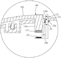
请参阅图13与图14所示,图13是本发明第六实施例中,调整元件、第一磁作用件与第二磁作用件的外观立体图,图12是本发明第六实施例中,按键结构的局部放大剖视图。在第六实施例中,调整元件包含轴杆190以及转盘200。使用时,轴杆190可转动地设置于基座130,转盘200设置于轴杆190并且位于容置空间136中。第二磁作用件120设于转盘200的外周面,通过转盘200转动,而改变第二磁作用件120的位置,而改变第一磁作用件110与第二磁作用件120之间的间隔距离,进而改变第一磁作用件110与第二磁作用件120之间常态地互相吸引或排斥(图13与图14中示出的是以磁力相互吸的实施例,在第六实施例的基础上参考图5以及图6中的结构稍作修改即可实现磁力排斥的实施例,此处不做赘述)时的磁力值。Please refer to FIG. 13 and FIG. 14. FIG. 13 is an external perspective view of the adjusting element, the first magnetic action piece and the second magnetic action piece in the sixth embodiment of the present invention, and FIG. 12 is the sixth embodiment of the present invention, A partial enlarged cross-sectional view of the key structure. In the sixth embodiment, the adjustment element includes a
如图14所示,上表面130a开设有开孔130d,按键板140的凸柱144a穿过开孔130d,使第一磁作用件110位于容置空间136中。第六实施例不排除省略凸柱144a,使得第一磁作用件110设置于按键板140的复位端144,并位于按键板140朝向基座130的一面且相对应于开孔130d;或是,进一步地省略开孔130d的设置,使得第一磁作用件110与容置空间136之间被基座130的实体部分隔开。As shown in FIG. 14 , an
如图13与图14所示,基座130的上表面130a凹设有内凹部130g,且内凹部130g通过穿置孔130h连通基座130的容置空间136。内凹部130g与容置空间136的连接处设置轴座130i。轴杆190具有穿置端191、转柄192以及凸缘部193。轴杆190穿过穿置孔130h,使得穿置端191位于容置空间136中,且转柄192位于内凹部130g。凸缘部193位于穿置端191与转柄192之间,并且嵌入轴座130i,以可转动地固定轴杆190于基座130。转盘200位于容置空间136中,并且相对应于开孔130d与第一磁作用件110。As shown in FIG. 13 and FIG. 14 , the
如图13、图14、图15以及图16所示,转柄192用以供使用者以手转动,带动转盘200转动,而改变第二磁作用件120的位置。第二磁作用件120的位置改变,改变了第一磁作用件110与第二磁作用件120之间的间隔距离,进而改变第一磁作用件110与第二磁作用件120之间常态地互相吸引时的磁力值。因此,通过使用转柄192转动轴杆190,可改变使用者按压按键板140的手感。As shown in FIG. 13 , FIG. 14 , FIG. 15 and FIG. 16 , the
如图15与图16所示,在至少一实施例中,按键结构1具有多个相同的第二磁作用件120,且多个第二磁作用件120被区分为多个群组。多个群组分别设置于转盘200的外周面上的不同位置,并且各群组具有的第二磁作用件120的数量不同。因此,当不同群组的第二磁作用件120通过转动轴杆190而相对应于第一磁作用件110时,将提供不同的磁力值,改变使用者按压按键板140的手感。As shown in FIGS. 15 and 16 , in at least one embodiment, the
如图15与图16所示,在不同实施例中,按键结构1具有多个不同(如体积不同等)的第二磁作用件120,且多个第二磁作用件120分别设置于转盘200的外周面上的不同位置。因此,当不同的第二磁作用件120通过转动轴杆190而相应于第一磁作用件110时,将提供不同的磁力值,改变使用者按压按键板140的手感。As shown in FIG. 15 and FIG. 16 , in different embodiments, the
如图19与图20所示,在第三实施例或第四实施例中,作为调整元件的移动件170上也可以设置多个第二磁作用件120。如图19所示,按键结构1具有多个相同的第二磁作用件120,且多个第二磁作用件120被区分为多个群组。多个群组分别设置于移动件170上的不同位置,并且各群组具有的第二磁作用件120的数量不同。因此,当不同群组的第二磁作用件120通过移动移动件170而相应于第一磁作用件110时,将提供不同的磁力值,改变使用者按压按键板140的手感。如图18所示,按键结构1具有多个不同的第二磁作用件120,且多个第二磁作用件120分别设置于移动件170上的不同位置。因此,当不同的第二磁作用件120通过移动移动件170而相应于第一磁作用件110时,将提供不同的磁力值,改变使用者按压按键板140的手感。As shown in FIG. 19 and FIG. 20 , in the third embodiment or the fourth embodiment, a plurality of second
请参阅图21、图22以及图23所示,为本发明第七实施例所公开的一种按键结构1。第七实施例中的调整元件省略了转盘200的配置,而是将第二磁作用件120设置于轴杆190上,且第二磁作用件120是偏心设置的转动元件,例如将第二磁作用件120设置为凸轮型态。如图20与图21所示,随着转柄192带动轴杆190转动,第二磁作用件120与第一磁作用件110之间的最小间隔距离将随之改变,从而改变第一磁作用件110与第二磁作用件120之间常态地互相吸引或排斥(图21、图22以及图23中示出的是以磁力相互吸的实施例,在第七实施例的基础上参考图5以及图6中的结构稍作修改即可实现磁力排斥的实施例,此处不做赘述)时的磁力值。为了简化配置,在第七实施例中,第一磁作用件110为磁铁,而第二磁作用件120较佳为导磁元件,使得第二磁作用件120的转动过程不需考虑磁极方向改变造成磁吸力转换为斥力。Please refer to FIG. 21 , FIG. 22 and FIG. 23 , which is a
请参阅图24、图25以及图26所示,为本发明第八实施例所公开的一种按键结构1。第八实施例的调整元件省略了转盘200的配置。调整元件进一步包含两个导引盘210以及导引座220。两个导引盘210设置于轴杆190上,并且两个导引盘210上设置相应的螺旋线槽212。导引座220的相对的两个侧面设置有导引杆222,各导引杆222分别可滑动地插入螺旋线槽212。第二磁作用件120设置于导引座220上,并且相对应于第一磁作用件110(通过开孔130d或相隔着基座130的实体部分)。第二磁作用件120常态地受到第一磁作用件110吸引或排斥(图21、图22以及图23中示出的是以磁力相互吸的实施例,在第八实施例的基础上参考图5以及图6中的结构稍作修改即可实现磁力排斥的实施例,此处不做赘述),而维持第二磁作用件120指向第一磁作用件110的状态。如图23与图24所示,随着转柄192带动轴杆190转动,导引杆222滑动于螺旋线槽212中,而改变第二磁作用件120与第一磁作用件110之间的间隔距离,从而改变第一磁作用件110与第二磁作用件120之间常态地互相吸引时的磁力值。Please refer to FIG. 24 , FIG. 25 and FIG. 26 , which is a
综上所述,本发明通过第一磁作用件110与第二磁作用件120之间通过磁力互相吸引或排斥,提供没有磨损问题的按压阻力和手感反馈,而可适用于欠缺手感反馈的开关装置,例如光开关160。手感产生过程中不涉及实体连接元件之间的干涉运动,可避免元件之间的操作磨损。通过磁作用件之间的相对位置、数量变化调整,本发明也可以快速增加或减少按压阻力或手感反馈的大小程度。此外,前述各实施例介绍的各种磁作用件(组)的设置位置,可以对应于按键板用于枢接部的前后两侧,例如各磁作用件(组)可位于枢接部146和按键板靠前侧 (如对应鼠标左右键的手指按压位置),或者各磁作用件(组)可位于枢接部和按键板靠后侧 (如对应鼠标左右键的操作手指的根部位置或邻近手掌前缘位置)。To sum up, the present invention provides pressing resistance and feel feedback without wear and tear through magnetic attraction or repulsion between the first
当然,本发明还可有其它多种实施例,在不背离本发明精神及其实质的情况下,熟悉本领域的技术人员可根据本发明作出各种相应的改变和变形,但这些相应的改变和变形都应属于本发明所附的权利要求的保护范围。Of course, the present invention can also have other various embodiments, without departing from the spirit and essence of the present invention, those skilled in the art can make various corresponding changes and deformations according to the present invention, but these corresponding changes and deformation should belong to the protection scope of the appended claims of the present invention.
Claims (22)
Applications Claiming Priority (2)
| Application Number | Priority Date | Filing Date | Title |
|---|---|---|---|
| TW110147046 | 2021-12-15 | ||
| TW110147046 | 2021-12-15 |
Publications (2)
| Publication Number | Publication Date |
|---|---|
| CN114446696A true CN114446696A (en) | 2022-05-06 |
| CN114446696B CN114446696B (en) | 2024-03-22 |
Family
ID=81366811
Family Applications (1)
| Application Number | Title | Priority Date | Filing Date |
|---|---|---|---|
| CN202210067597.6A Active CN114446696B (en) | 2021-12-15 | 2022-01-20 | Button structure |
Country Status (3)
| Country | Link |
|---|---|
| US (1) | US20230187147A1 (en) |
| CN (1) | CN114446696B (en) |
| TW (1) | TWI789212B (en) |
Cited By (1)
| Publication number | Priority date | Publication date | Assignee | Title |
|---|---|---|---|---|
| WO2024138464A1 (en) * | 2022-12-28 | 2024-07-04 | Logitech Europe S.A. | Computer mouse with non-impact magnet-based switch |
Citations (5)
| Publication number | Priority date | Publication date | Assignee | Title |
|---|---|---|---|---|
| TWM432878U (en) * | 2012-03-22 | 2012-07-01 | Darfon Electronics Corp | Magnetic keyswitch assembly and keyboard |
| DE202012002710U1 (en) * | 2012-03-15 | 2012-07-02 | Cheng Uei Precision Industry Co., Ltd. | Mouse setup |
| US20170285768A1 (en) * | 2016-03-31 | 2017-10-05 | Azoteq (Pty) Ltd | Rotational sensing |
| US20190146600A1 (en) * | 2017-11-10 | 2019-05-16 | Primax Electronics Ltd. | Mouse device with button feedback mechanism |
| CN113342191A (en) * | 2021-06-23 | 2021-09-03 | 深圳市富吉电子有限公司 | Mouse with adjustable button pressure |
Family Cites Families (2)
| Publication number | Priority date | Publication date | Assignee | Title |
|---|---|---|---|---|
| US10022622B2 (en) * | 2014-04-21 | 2018-07-17 | Steelseries Aps | Programmable actuation inputs of an accessory and methods thereof |
| TWM570463U (en) * | 2018-06-29 | 2018-11-21 | 宏碁股份有限公司 | Mouse device |
-
2022
- 2022-01-18 TW TW111102080A patent/TWI789212B/en active
- 2022-01-20 CN CN202210067597.6A patent/CN114446696B/en active Active
- 2022-08-24 US US17/821,814 patent/US20230187147A1/en active Pending
Patent Citations (5)
| Publication number | Priority date | Publication date | Assignee | Title |
|---|---|---|---|---|
| DE202012002710U1 (en) * | 2012-03-15 | 2012-07-02 | Cheng Uei Precision Industry Co., Ltd. | Mouse setup |
| TWM432878U (en) * | 2012-03-22 | 2012-07-01 | Darfon Electronics Corp | Magnetic keyswitch assembly and keyboard |
| US20170285768A1 (en) * | 2016-03-31 | 2017-10-05 | Azoteq (Pty) Ltd | Rotational sensing |
| US20190146600A1 (en) * | 2017-11-10 | 2019-05-16 | Primax Electronics Ltd. | Mouse device with button feedback mechanism |
| CN113342191A (en) * | 2021-06-23 | 2021-09-03 | 深圳市富吉电子有限公司 | Mouse with adjustable button pressure |
Cited By (1)
| Publication number | Priority date | Publication date | Assignee | Title |
|---|---|---|---|---|
| WO2024138464A1 (en) * | 2022-12-28 | 2024-07-04 | Logitech Europe S.A. | Computer mouse with non-impact magnet-based switch |
Also Published As
| Publication number | Publication date |
|---|---|
| TW202326346A (en) | 2023-07-01 |
| TWI789212B (en) | 2023-01-01 |
| US20230187147A1 (en) | 2023-06-15 |
| CN114446696B (en) | 2024-03-22 |
Similar Documents
| Publication | Publication Date | Title |
|---|---|---|
| TWI607476B (en) | Keyswitch structure | |
| US10937610B2 (en) | Keyboard keyswitches having adjustable tactile feedback members | |
| JP2004235059A (en) | Recording medium ejection button switch of composite equipment | |
| TW201608586A (en) | Keyswitch structure | |
| JP2018107088A (en) | Contact structure of switch, trigger switch, and power tool | |
| CN114446696A (en) | Key structure | |
| TW202042265A (en) | Keyswitch structure | |
| EP3611600B1 (en) | Keyboard | |
| TWM606963U (en) | Mechanical keyboard | |
| CN101226839A (en) | Micro-switch | |
| TWM595258U (en) | Mouse pressing structure | |
| EP0075088A1 (en) | Nutating snap action switch apparatus | |
| EP3975217B1 (en) | Keyboard key | |
| TW202025190A (en) | Keyboard | |
| CN114527885A (en) | Mouse (Saggar) | |
| CN216486378U (en) | Mouse (Saggar) | |
| CN108666162B (en) | Keyboard device and key structure thereof | |
| TWI777591B (en) | Mouse apparatus | |
| JP6303380B2 (en) | Click mechanism and dial equipped with it | |
| US8704119B2 (en) | Thin profile cam switch assemblies | |
| JP2005026035A (en) | Switch | |
| TWM535391U (en) | Key structure and electronic device using the same | |
| JP7059964B2 (en) | Switch device and key input device | |
| TWI666669B (en) | Resilient contact and input device | |
| US7763817B2 (en) | Button assembly |
Legal Events
| Date | Code | Title | Description |
|---|---|---|---|
| PB01 | Publication | ||
| PB01 | Publication | ||
| SE01 | Entry into force of request for substantive examination | ||
| SE01 | Entry into force of request for substantive examination | ||
| GR01 | Patent grant | ||
| GR01 | Patent grant |