CN114446619A - A kind of on-load tap changer series load single resistance transition circuit and voltage regulation method - Google Patents
A kind of on-load tap changer series load single resistance transition circuit and voltage regulation method Download PDFInfo
- Publication number
- CN114446619A CN114446619A CN202210138035.6A CN202210138035A CN114446619A CN 114446619 A CN114446619 A CN 114446619A CN 202210138035 A CN202210138035 A CN 202210138035A CN 114446619 A CN114446619 A CN 114446619A
- Authority
- CN
- China
- Prior art keywords
- switch
- switching element
- tap
- load
- main
- Prior art date
- Legal status (The legal status is an assumption and is not a legal conclusion. Google has not performed a legal analysis and makes no representation as to the accuracy of the status listed.)
- Pending
Links
- 230000007704 transition Effects 0.000 title claims description 94
- 238000000034 method Methods 0.000 title claims description 50
- 238000004804 winding Methods 0.000 claims description 78
- 230000008569 process Effects 0.000 claims description 31
- 230000003068 static effect Effects 0.000 claims description 21
- 230000007935 neutral effect Effects 0.000 claims description 19
- 230000001105 regulatory effect Effects 0.000 claims description 11
- 238000002955 isolation Methods 0.000 claims description 6
- 238000010586 diagram Methods 0.000 description 18
- 230000009471 action Effects 0.000 description 15
- 238000011084 recovery Methods 0.000 description 4
- 230000005540 biological transmission Effects 0.000 description 2
- 230000007774 longterm Effects 0.000 description 2
- 238000012423 maintenance Methods 0.000 description 2
- 238000012986 modification Methods 0.000 description 2
- 230000004048 modification Effects 0.000 description 2
- 230000009286 beneficial effect Effects 0.000 description 1
- 238000003763 carbonization Methods 0.000 description 1
- 230000008859 change Effects 0.000 description 1
- 150000001875 compounds Chemical class 0.000 description 1
- 238000009833 condensation Methods 0.000 description 1
- SBYXRAKIOMOBFF-UHFFFAOYSA-N copper tungsten Chemical compound [Cu].[W] SBYXRAKIOMOBFF-UHFFFAOYSA-N 0.000 description 1
- 238000005260 corrosion Methods 0.000 description 1
- 230000007797 corrosion Effects 0.000 description 1
- 230000009977 dual effect Effects 0.000 description 1
- 230000000694 effects Effects 0.000 description 1
- 230000005284 excitation Effects 0.000 description 1
- 238000010304 firing Methods 0.000 description 1
- 230000007246 mechanism Effects 0.000 description 1
Images


Classifications
-
- H—ELECTRICITY
- H01—ELECTRIC ELEMENTS
- H01F—MAGNETS; INDUCTANCES; TRANSFORMERS; SELECTION OF MATERIALS FOR THEIR MAGNETIC PROPERTIES
- H01F29/00—Variable transformers or inductances not covered by group H01F21/00
- H01F29/02—Variable transformers or inductances not covered by group H01F21/00 with tappings on coil or winding; with provision for rearrangement or interconnection of windings
- H01F29/04—Variable transformers or inductances not covered by group H01F21/00 with tappings on coil or winding; with provision for rearrangement or interconnection of windings having provision for tap-changing without interrupting the load current
-
- H—ELECTRICITY
- H01—ELECTRIC ELEMENTS
- H01H—ELECTRIC SWITCHES; RELAYS; SELECTORS; EMERGENCY PROTECTIVE DEVICES
- H01H9/00—Details of switching devices, not covered by groups H01H1/00 - H01H7/00
- H01H9/0005—Tap change devices
-
- H—ELECTRICITY
- H01—ELECTRIC ELEMENTS
- H01H—ELECTRIC SWITCHES; RELAYS; SELECTORS; EMERGENCY PROTECTIVE DEVICES
- H01H9/00—Details of switching devices, not covered by groups H01H1/00 - H01H7/00
- H01H9/0005—Tap change devices
- H01H9/0016—Contact arrangements for tap changers
-
- H—ELECTRICITY
- H01—ELECTRIC ELEMENTS
- H01H—ELECTRIC SWITCHES; RELAYS; SELECTORS; EMERGENCY PROTECTIVE DEVICES
- H01H9/00—Details of switching devices, not covered by groups H01H1/00 - H01H7/00
- H01H9/0005—Tap change devices
- H01H2009/0061—Monitoring tap change switching devices
Landscapes
- Engineering & Computer Science (AREA)
- Power Engineering (AREA)
- High-Tension Arc-Extinguishing Switches Without Spraying Means (AREA)
Abstract
一种有载分接开关串联负载单电阻过渡电路及调压方法,包括第一主通流开关;第一主通断开关的第一端与第一开关元件的第一端相连,第一主通断开关的第二端与第三开关元件的第一端、过渡电阻的第一端、第四开关元件的第一端和第二主通流开关的第一端均相连,第一开关元件的第二端以及与第三开关元件的第二端均与转换开关的第一静触点相连,过渡电阻的第二端与转换开关的动触点相连,第二主通流开关的第二端与第二开关元件的第一端相连,第二开关元件的第二端和第四开关元件的第二端均与转换开关的第二静触点相连。过渡电路中两个负载电流开断元件轮流开断负载电流,两个环流开断元件工作损耗程度一致,提高了有载分接开关的可靠性和电气寿命。

An on-load tap changer series-loaded single-resistor transition circuit and a voltage regulation method, comprising a first main current on-off switch; a first end of the first main on-off switch is connected with a first end of a first switching element, and the first main The second end of the on-off switch is connected to the first end of the third switching element, the first end of the transition resistor, the first end of the fourth switching element and the first end of the second main current-passing switch, and the first switching element The second end of the transition resistor and the second end of the third switch element are connected to the first static contact of the transfer switch, the second end of the transition resistor is connected to the moving contact of the transfer switch, and the second end of the second main current switch The terminal is connected to the first terminal of the second switch element, and the second terminal of the second switch element and the second terminal of the fourth switch element are both connected to the second stationary contact of the transfer switch. The two load current breaking elements in the transition circuit alternately break the load current, and the working loss of the two circulating current breaking elements is the same, which improves the reliability and electrical life of the on-load tap-changer.
Description
技术领域technical field
本发明涉及有载分接开关技术领域,特别涉及一种有载分接开关串联负载单电阻过渡电路及调压方法。The invention relates to the technical field of on-load tap changers, in particular to an on-load tap changer series-loaded single-resistor transition circuit and a voltage regulation method.
背景技术Background technique
有载分接开关是电力变压器内部的关键组件,能够在变压器励磁或负载状态下操作、变化连接变压器绕组中引出的若干分接头改变有效匝数比,实现在不中断负载电流的情况下调节输出电压。有载分接开关应用范围广泛,尤其应用在特高压直流输电工程的换流变压器中,以保证换流器在正常运行时的额定触发角。早期电力变压器所配的有载分接开关大都采用高速电阻切换原理,靠铜钨电弧触头进行负载转换。这类油浸式非有载分接开关切换频繁,电弧触头烧损相应比较严重,油的碳化和污染速度较快,因此给供电部门增加了日常维护和定期检修工作量。真空式有载分接开关,主要使用真空管来实现电弧熄灭,避免了油中熄弧对油的碳化和污染;由于真空管开断燃弧时间短、弧压低、电弧能耗小以及触头金属气化物的重凝,触头烧损腐蚀可以降到最低限度。电力电子式有载分接开关,通过电力电子元件替代真空管从而实现有载切换过程中无开断电弧操作。The on-load tap-changer is a key component inside the power transformer. It can operate under the transformer excitation or load state, change the effective turns ratio by changing several taps drawn from the transformer winding, and adjust the output without interrupting the load current. Voltage. The on-load tap-changer has a wide range of applications, especially in the converter transformer of the UHV DC transmission project to ensure the rated firing angle of the converter during normal operation. Most of the on-load tap-changers equipped with early power transformers adopted the principle of high-speed resistance switching, relying on copper-tungsten arc contacts for load switching. This type of oil-immersed non-on-load tap-changer switches frequently, the arc contact burns relatively seriously, and the oil is carbonized and polluted quickly, thus increasing the daily maintenance and regular maintenance workload for the power supply department. The vacuum type on-load tap-changer mainly uses the vacuum tube to realize the arc extinguishing, which avoids the carbonization and pollution of the oil caused by the arc extinguishing in the oil; The re-condensation of the compound, the contact burning and corrosion can be reduced to a minimum. The power electronic on-load tap-changer replaces the vacuum tube with power electronic components to realize the arc-free operation during the on-load switching process.
有载分接开关由切换开关、分接选择器和电动机构组成。其中切换开关有独立的油室,是分接开关实现有载切换的关键组件,其核心是采用了过渡电路。真空式有载分接开关按其真空管的个数不同可分为单触点电路、双触点电路、三触点电路和四触点电路;按其过渡电阻的数目不同有单电阻、双电阻过渡两种;按其触头断口数目有单断口、双断口等;上述各种组合可构成各式各样的真空式有载分接开关过渡电路。过渡电路中的开关元件可以是单断口真空触头、双断口真空触头、电力电子元件等;不同的过渡电路为了实现有载切换调压有着不同的切换时序,各开关元件的切换任务也会有所不同。过渡电路的拓扑结构对有载分接开关切换过程的可靠性,以及开关的故障率和电气寿命都有明显的影响。The on-load tap-changer consists of a diverter switch, a tap selector and an electric mechanism. Among them, the switch has an independent oil chamber, which is the key component for the on-load switching of the tap changer. The core of the switch is the use of a transition circuit. Vacuum on-load tap-changers can be divided into single-contact circuit, double-contact circuit, three-contact circuit and four-contact circuit according to the number of vacuum tubes; according to the number of transition resistances, there are single resistance, double resistance There are two types of transition; according to the number of contact fractures, there are single fracture, double fracture, etc. The above combinations can form various transition circuits of vacuum on-load tap-changers. The switching elements in the transition circuit can be single-break vacuum contacts, double-break vacuum contacts, power electronic components, etc.; different transition circuits have different switching sequences in order to realize on-load switching and voltage regulation, and the switching tasks of each switching element will also be different. The topology of the transition circuit has a significant impact on the reliability of the on-load tap-changer switching process, as well as on the failure rate and electrical life of the switch.
有载分接开关过渡电路中,有着只承担开断负载电流任务的负载电流真空断路器和只承担开断级间环流任务的环流真空断路器。在特高压直流输电工程实际中,流过换流变压器有载分接开关中的负载电流约为500~600A,切换过程中流过过渡电阻的级间环流约为900~1000A,环流真空断路器单次开断的环流明显大于负载电流真空断路器开断的负载电流,导致负载电流真空断路器和环流真空断路器开断任务不平衡。In the transition circuit of the on-load tap-changer, there are load current vacuum circuit breakers that only undertake the task of breaking the load current and circulating current vacuum circuit breakers that only undertake the task of breaking the circulating current between stages. In the actual UHVDC transmission project, the load current flowing through the on-load tap-changer of the converter transformer is about 500-600A, and the interstage circulating current flowing through the transition resistance during the switching process is about 900-1000A. The circulating current of the secondary breaking is obviously larger than the load current of the load current vacuum circuit breaker, which leads to the imbalance of the breaking tasks of the load current vacuum circuit breaker and the circulating current vacuum circuit breaker.
发明内容SUMMARY OF THE INVENTION
本发明提出一种有载分接开关串联负载单电阻过渡电路及调压方法,具有过渡电阻少、环流真空断路器与负载电流真空断路器均双重化配置,交替切断电流的优点,元件分布对称,切换时序对称,可提高有载分接开关的可靠性和切换效率。The invention proposes an on-load tap-changer series load single-resistance transition circuit and a voltage regulation method, which have the advantages of less transition resistance, dual configuration of circulating current vacuum circuit breaker and load current vacuum circuit breaker, alternating current cutoff, and symmetrical distribution of components , the switching sequence is symmetrical, which can improve the reliability and switching efficiency of the on-load tap-changer.
本发明目的通过如下技术方案予以实现:The object of the present invention is achieved through the following technical solutions:
一种有载分接开关串联负载单电阻过渡电路,包括第一主通流开关和第二主通流开关,作为环流开断元件的第一开关元件和第二开关元件,作为负载电流开关元件的第三开关元件和第四开关元件,转换开关以及过渡电阻;An on-load tap changer series load single-resistor transition circuit, comprising a first main current switch and a second main current switch, a first switch element and a second switch element as circulating current breaking elements, as load current switch elements The third switching element and the fourth switching element, the transfer switch and the transition resistance;
其中,第一主通断开关的第一端与第一开关元件的第一端相连,第一主通断开关的第二端与第三开关元件的第一端、过渡电阻的第一端、第四开关元件的第一端和第二主通流开关的第一端均相连,第一开关元件的第二端以及与第三开关元件的第二端均与转换开关的第一静触点相连,过渡电阻的第二端与转换开关的动触点相连,第二主通流开关的第二端与第二开关元件的第一端相连,第二开关元件的第二端和第四开关元件的第二端均与转换开关的第二静触点相连。Wherein, the first end of the first main on-off switch is connected with the first end of the first switching element, the second end of the first main on-off switch is connected with the first end of the third switching element, the first end of the transition resistance, The first end of the fourth switch element is connected to the first end of the second main current switch, and the second end of the first switch element and the second end of the third switch element are both connected to the first static contact of the transfer switch. connected, the second end of the transition resistor is connected to the moving contact of the transfer switch, the second end of the second main current switch is connected to the first end of the second switch element, the second end of the second switch element is connected to the fourth switch The second ends of the elements are all connected with the second stationary contact of the transfer switch.
进一步的,还包括第一隔离开关,第三开关元件的第二端经第一隔离开关与转换开关的第一静触点相连。Further, it also includes a first isolating switch, and the second end of the third switching element is connected to the first static contact of the transfer switch via the first isolating switch.
进一步的,还包括第二隔离开关,第四开关元件的第二端经第二隔离开关与转换开关的第二静触点相连。Further, a second isolating switch is also included, and the second end of the fourth switching element is connected to the second static contact of the transfer switch via the second isolating switch.
进一步的,第一开关元件、第二开关元件、第三开关元件和第四开关元件为单断口真空断路器、双断口真空断路器或具有可控制通断功能的电力电子元件。Further, the first switching element, the second switching element, the third switching element and the fourth switching element are single-break vacuum circuit breakers, double-break vacuum circuit breakers or power electronic components with controllable on-off functions.
进一步的,还包括有载分接开关调压绕组,第二主通流开关的第二端与第二开关元件的第一端均与有载分接开关调压第二绕组抽头相连,第一主通断开关的第一端和第一开关元件的第一端均与有载分接开关调压第一绕组抽头N相连。Further, it also includes a voltage regulating winding of the on-load tap-changer, the second end of the second main current switch and the first end of the second switching element are both connected to the tap of the second winding of the on-load tap-changer voltage regulating, the first The first end of the main on-off switch and the first end of the first switching element are both connected to the tap N of the first winding for voltage regulation of the on-load tap changer.
进一步的,还包括有载分接开关,第三开关元件的第一端、过渡电阻的第一端、第四开关元件的第一端、第一主通流开关的第二端和第二主通流开关的第一端均与有载分接开关的中性点引出端相连。Further, it also includes an on-load tap changer, the first end of the third switching element, the first end of the transition resistor, the first end of the fourth switching element, the second end of the first main current switch and the second main The first ends of the current-passing switch are all connected with the neutral point lead-out end of the on-load tap changer.
进一步的,第三开关元件用于从第一绕组抽头切换至第二绕组抽头过程中开断负载电流,第四开关元件用于从第二绕组抽头切换至第一绕组抽头过程中开断负载电流;Further, the third switching element is used to interrupt the load current during the process of switching from the first winding tap to the second winding tap, and the fourth switching element is used to interrupt the load current during the process of switching from the second winding tap to the first winding tap. ;
第一开关元件用于从第一绕组抽头N切换至第二绕组抽头过程中,开断过渡电路桥接时的级间环流,第二开关元件用于从第二绕组抽头切换至第一绕组抽头过程中,开断过渡电路桥接时的级间环流;The first switching element is used for switching off the interstage circulating current when the transition circuit is bridged during the process of switching from the first winding tap N to the second winding tap, and the second switching element is used for switching from the second winding tap to the first winding tap. , the inter-stage circulating current when the transition circuit is bridged;
所述过渡电阻,用于过渡电路切换过程中限制第一绕组抽头和第二绕组抽头桥接时的级间环流。The transition resistance is used to limit the inter-stage circulating current when the first winding tap and the second winding tap are bridged during the switching process of the transition circuit.
一种基于上述的有载分接开关串联负载单电阻过渡电路的调压方法,包括以下步骤:A voltage regulation method based on the above-mentioned on-load tap-changer series load single-resistance transition circuit, comprising the following steps:
第一主通断开关、第三开关元件与第一开关元件置于导通状态,第二主通断开关、第四开关元件与第二开关元件置于断开状态;The first main on-off switch, the third switch element and the first switch element are placed in an on state, and the second main on-off switch, the fourth switch element and the second switch element are placed in an off state;
将第一主通断开关断开,将转换开关从空置切换至第一静触点,将第二开关元件导通,将第三开关元件断开,将第四开关元件导通,将第一开关元件断开,将转换开关从第一静触点切换至空置,将第二主通断开关导通,有载分接开关从调压第一绕组抽头切换到调压第二绕组抽头。Turn off the first main on-off switch, switch the transfer switch from vacant to the first static contact, turn on the second switching element, turn off the third switching element, turn on the fourth switching element, and turn the first switching element on. The switching element is turned off, the transfer switch is switched from the first static contact to the idle, the second main on-off switch is turned on, and the on-load tap changer is switched from the tap of the first winding of the voltage regulation to the tap of the second winding of the voltage regulation.
一种基于上述的有载分接开关串联负载单电阻过渡电路的调压方法,第二主通断开关处于导通状态,第一主通断开关处于断开状态,第四开关元件处于导通状态,第三开关元件处于断开状态,第二开关元件处于导通状态,第一开关元件处于断开状态;A voltage regulation method based on the above-mentioned on-load tap changer series load single-resistance transition circuit, the second main on-off switch is in an on state, the first main on-off switch is in an off state, and the fourth switch element is in a conductive state state, the third switch element is in the off state, the second switch element is in the on state, and the first switch element is in the off state;
将第二主通断开关断开,将转换开关从空置切换至第二静触点,将第一开关元件导通,将第四开关元件断开,将第三开关元件导通,将第二开关元件断开,将转换开关从第二静触点切换至空置,将第一主通断开关导通,有载分接开关从调压第二绕组抽头切换到调压第一绕组抽头。Turn off the second main on-off switch, switch the transfer switch from vacant to the second static contact, turn on the first switching element, turn off the fourth switching element, turn on the third switching element, and turn the second switching element on. The switching element is turned off, the transfer switch is switched from the second static contact to the vacant position, the first main on-off switch is turned on, and the on-load tap changer is switched from the tap of the second winding of the voltage regulation to the tap of the first winding of the voltage regulation.
与现有技术相比,本发明具有的有益效果:Compared with the prior art, the present invention has the following beneficial effects:
本发明提供了一种有载分接开关串联负载单电阻过渡电路及调压方法,过渡电路中存在两个负载电流开断元件,轮流开断负载电流;存在两个环流开断元件,轮流开断有载切换过程中的级间环流,切换程序对称,两个环流开断元件工作损耗程度一致,减轻了环流开断元件的切换损耗,能够平衡负载电流开断元件和环流开断元件的切换容量,极大提高了有载分接开关的电气寿命。The invention provides an on-load tap changer series load single-resistance transition circuit and a voltage regulation method. There are two load current interrupting elements in the transition circuit, and the load current is interrupted in turn; there are two circulating current interrupting elements, which alternately open Inter-stage circulating current is interrupted in the process of on-load switching, the switching procedure is symmetrical, the working loss of the two circulating current interrupting elements is the same, the switching loss of the circulating current interrupting element is reduced, and the switching of the load current interrupting element and the circulating current interrupting element can be balanced. capacity, greatly improving the electrical life of the on-load tap-changer.
进一步的,在电路中设置第一隔离开关与第二隔离开关,以起到当断路器失效时,断开电路连接的作用。Further, a first isolating switch and a second isolating switch are arranged in the circuit, so as to disconnect the circuit when the circuit breaker fails.
附图说明Description of drawings
图1为本发明的有载分接开关串联负载单电阻过渡电路的电路图;Fig. 1 is the circuit diagram of the on-load tap changer series load single resistance transition circuit of the present invention;
图2为本发明的有载分接开关串联负载单电阻过渡电路切换过程的示意图;Fig. 2 is the schematic diagram of the switching process of the on-load tap changer series load single-resistance transition circuit of the present invention;
图3为本发明的有载分接开关串联负载单电阻过渡电路切换过程的示意图;3 is a schematic diagram of the switching process of the on-load tap-changer series load single-resistance transition circuit of the present invention;
图4为本发明的有载分接开关串联负载单电阻过渡电路切换过程的示意图;4 is a schematic diagram of a switching process of an on-load tap-changer connected in series with a single-resistor transition circuit of the present invention;
图5为本发明的有载分接开关串联负载单电阻过渡电路切换过程的示意图;5 is a schematic diagram of the switching process of the on-load tap changer series load single-resistance transition circuit of the present invention;
图6为本发明的有载分接开关串联负载单电阻过渡电路切换过程的示意图;6 is a schematic diagram of the switching process of the on-load tap changer series load single-resistance transition circuit of the present invention;
图7为本发明的有载分接开关串联负载单电阻过渡电路切换过程的示意图;7 is a schematic diagram of a switching process of an on-load tap-changer connected in series with a single-resistor transition circuit of the present invention;
图8为本发明的有载分接开关串联负载单电阻过渡电路切换过程的示意图;8 is a schematic diagram of a switching process of an on-load tap changer connected in series with a single-resistor transition circuit of the present invention;
图9为本发明的有载分接开关串联负载单电阻过渡电路切换过程的示意图;9 is a schematic diagram of a switching process of an on-load tap-changer connected in series with a single-resistor transition circuit of the present invention;
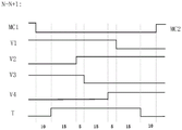
图10为负载从绕组抽头N切换到绕组抽头N+1过程中本发明的有载分接开关串联负载单电阻过渡电路中各开关通断的示意图;10 is a schematic diagram of the on-off of each switch in the on-load tap-changer series load single-resistance transition circuit of the present invention during the process of switching the load from the winding tap N to the winding tap N+1;
图11为负载从绕组抽头N+1切换到绕组抽头N过程中本发明的有载分接开关串联负载单电阻过渡电路中各开关通断的示意图;11 is a schematic diagram of the on-off of each switch in the on-load tap-changer series load single-resistance transition circuit of the present invention during the process of switching the load from the winding tap N+1 to the winding tap N;
图12为根据本发明实施方式的开关元件为电力电子元件的有载分接开关串联负载单电阻过渡电路的电路图;12 is a circuit diagram of an on-load tap-changer series-loaded single-resistor transition circuit in which the switching element is a power electronic element according to an embodiment of the present invention;
图13为根据本发明实施方式的开关元件为双断口真空断路器的有载分接开关串联负载单电阻过渡电路的电路图;13 is a circuit diagram of an on-load tap-changer series-loaded single-resistance transition circuit in which the switching element is a double-break vacuum circuit breaker according to an embodiment of the present invention;
图14为根据本发明的有载分接开关串联负载单电阻过渡电路,在电路中添加示例隔离开关,从而起到电气隔离作用的电路图。14 is a circuit diagram of an on-load tap-changer connected in series with a load single-resistance transition circuit according to the present invention, and an example isolation switch is added to the circuit to achieve electrical isolation.
具体实施方式Detailed ways
下面结合附图对本发明进行详细说明。The present invention will be described in detail below with reference to the accompanying drawings.
为了使本技术领域的人员更好地理解本发明方案,下面将结合本发明实施例中的附图,对本发明实施例中的技术方案进行清楚、完整地描述,显然,所描述的实施例仅仅是本发明一部分的实施例,而不是全部的实施例。基于本发明中的实施例,本领域普通技术人员在没有做出创造性劳动前提下所获得的所有其他实施例,都应当属于本发明保护的范围。In order to make those skilled in the art better understand the solutions of the present invention, the technical solutions in the embodiments of the present invention will be clearly and completely described below with reference to the accompanying drawings in the embodiments of the present invention. Obviously, the described embodiments are only Embodiments are part of the present invention, but not all embodiments. Based on the embodiments of the present invention, all other embodiments obtained by persons of ordinary skill in the art without creative efforts shall fall within the protection scope of the present invention.
需要说明的是,本发明的说明书和权利要求书及上述附图中的术语“第一”、“第二”等是用于区别类似的对象,而不必用于描述特定的顺序或先后次序。应该理解这样使用的数据在适当情况下可以互换,以便这里描述的本发明的实施例能够以除了在这里图示或描述的那些以外的顺序实施。此外,术语“包括”和“具有”以及他们的任何变形,意图在于覆盖不排他的包含,例如,包含了一系列步骤或单元的过程、方法、系统、产品或设备不必限于清楚地列出的那些步骤或单元,而是可包括没有清楚地列出的或对于这些过程、方法、产品或设备固有的其它步骤或单元。It should be noted that the terms "first", "second" and the like in the description and claims of the present invention and the above drawings are used to distinguish similar objects, and are not necessarily used to describe a specific sequence or sequence. It is to be understood that the data so used may be interchanged under appropriate circumstances such that the embodiments of the invention described herein can be practiced in sequences other than those illustrated or described herein. Furthermore, the terms "comprising" and "having", and any variations thereof, are intended to cover non-exclusive inclusion, for example, a process, method, system, product or device comprising a series of steps or units is not necessarily limited to those expressly listed Rather, those steps or units may include other steps or units not expressly listed or inherent to these processes, methods, products or devices.
图1为本发明的有载分接开关串联负载单电阻过渡电路的电路图。如图1所示,本发明提供了一种有载分接开关串联负载单电阻过渡电路,过渡电路中存在两个负载电流开断元件,轮流开断负载电流;存在两个环流开断元件,轮流开断有载切换过程中的级间环流,切换程序对称,两个环流开断元件工作损耗程度一致,减轻了环流开断元件的切换损耗,能够平衡负载电流开断元件和环流开断元件的切换容量,极大提高了有载分接开关的电气寿命。FIG. 1 is a circuit diagram of an on-load tap changer connected in series with a single-resistor transition circuit of the present invention. As shown in FIG. 1 , the present invention provides an on-load tap-changer series load single-resistance transition circuit. There are two load current interrupting elements in the transition circuit, and the load current is interrupted in turn; there are two circulating current interrupting elements, The inter-stage circulating current in the on-load switching process is alternately interrupted, the switching procedure is symmetrical, the working loss of the two circulating current interrupting elements is the same, the switching loss of the circulating current interrupting element is reduced, and the load current interrupting element and the circulating current interrupting element can be balanced. The switching capacity of the switch greatly improves the electrical life of the on-load tap-changer.
具体的,本发明的有载分接开关串联负载单电阻过渡电路,包括:第一主通流开关MC1和第二主通流开关MC2,作为环流开断元件的第一开关元件V1和第二开关元件V2,作为负载电流开关元件的第三开关元件V3和第四开关元件V4,转换开关T以及过渡电阻R。Specifically, the on-load tap-changer series load single-resistance transition circuit of the present invention includes: a first main current switch MC1 and a second main current switch MC2, and a first switching element V1 and a second switching element V1 serving as circulating current breaking elements The switching element V2, the third switching element V3 and the fourth switching element V4 as load current switching elements, the changeover switch T and the transition resistance R.
其中,第一主通断开关MC1的第一端与第一开关元件V1的第一端和调压第一绕组抽头N均相连,第一主通断开关MC1的第二端与中性点引出端、第三开关元件V3的第一端、过渡电阻R的第一端、第四开关元件V4的第一端、第二主通流开关MC2的第一端和中性点引出端均相连,第一开关元件V1的第二端以及与第三开关元件V3的第二端均与转换开关T的第一静触点11相连,过渡电阻R的第二端与转换开关T的动触点相连,第二主通流开关MC2的第二端与第二开关元件V2的第一端相连,第二开关元件V2的第二端和第四开关元件V4的第二端均与转换开关T的第二静触点12相连,The first end of the first main on-off switch MC1 is connected to the first end of the first switching element V1 and the voltage regulating first winding tap N, and the second end of the first main on-off switch MC1 is connected to the neutral point. terminal, the first terminal of the third switching element V3, the first terminal of the transition resistance R, the first terminal of the fourth switching element V4, the first terminal of the second main current switch MC2 and the neutral point lead terminal are all connected, The second end of the first switching element V1 and the second end of the third switching element V3 are both connected to the first
第三开关元件V3的第一端、过渡电阻R的第一端、第四开关元件V4的第一端、第一主通流开关MC1的第二端和第二主通流开关MC2的第一端均与有载分接开关的中性点引出端相连。The first terminal of the third switching element V3, the first terminal of the transition resistor R, the first terminal of the fourth switching element V4, the second terminal of the first main current switch MC1, and the first terminal of the second main current switch MC2 The terminals are all connected to the neutral point terminal of the on-load tap-changer.
第二主通流开关MC2的第二端与第二开关元件V2的第一端均与有载分接开关调压第二绕组抽头N+1相连。The second end of the second main current switch MC2 and the first end of the second switching element V2 are both connected to the on-load tap changer voltage regulating second winding tap N+1.
优选的,还包括第一隔离开关Z1,第三开关元件V3的第二端经第一隔离开关Z1与转换开关T的第一静触点11相连。Preferably, a first isolating switch Z1 is also included, and the second end of the third switching element V3 is connected to the first
优选的,还包括第二隔离开关Z2,第四开关元件V4的第二端经第二隔离开关Z2与转换开关T的第二静触点12相连。Preferably, a second isolating switch Z2 is also included, and the second end of the fourth switching element V4 is connected to the second
优选的,第一开关元件V1、第一开关元件V2、第三开关元件V3和第四开关元件V4为单断口真空断路器、双断口真空断路器或具有可控制通断功能的电力电子元件。Preferably, the first switching element V1 , the first switching element V2 , the third switching element V3 and the fourth switching element V4 are single-break vacuum circuit breakers, double-break vacuum circuit breakers or power electronic components with controllable on-off functions.
具体的,所述转换开关T,具有第一静触点11和第二静触点12和一个动作臂(动触点),所述第一静触点11连接第一开关元件V1的一端和第三开关元件V3的一端,第一开关元件V1的另一端调压第一绕组抽头N,所述第二静触点12连接环流真空断路器V2的一端和第四开关元件V4的一端,第二开关元件V2的另一端调压第二绕组抽头N+1,所述动作臂连接第一静触点11和第二静触点12的任意一个,动作臂也可作为空置状态,既不连接第一静触点11也不连接第二静触点12。Specifically, the transfer switch T has a first
使用时,所述第一主通流开关MC1用于有载分接开关调压第一绕组抽头N到中性点引出端的负载电流长期载流;所述主通流开关MC2用于有载分接开关调压第二绕组抽头N+1到中性点引出端的负载电流长期载流。When in use, the first main current switch MC1 is used for the on-load tap changer to adjust the load current from the tap N of the first winding to the long-term current carrying of the load current from the neutral point terminal; the main current switch MC2 is used for the on-load tap changer. Connect the switch to adjust the load current from the second winding tap N+1 to the neutral point lead-out end for long-term current carrying.
第三开关元件V3用于从第一绕组抽头N切换至第二绕组抽头N+1过程中开断负载电流,第四开关元件V4用于从第二绕组抽头N+1切换至第一绕组抽头N过程中开断负载电流。The third switching element V3 is used for switching off the load current during switching from the first winding tap N to the second winding tap N+1, and the fourth switching element V4 is used for switching from the second winding tap N+1 to the first winding tap The load current is interrupted during the N process.
第一开关元件V1用于从第一绕组抽头N切换至第二绕组抽头N+1过程中,开断过渡电路桥接时的级间环流,第二开关元件V2用于从第二绕组抽头N+1切换至第一绕组抽头N过程中,开断过渡电路桥接时的级间环流。The first switching element V1 is used to switch off the interstage circulating current when the transition circuit is bridged during the process of switching from the first winding tap N to the second winding tap N+1, and the second switching element V2 is used to tap the N+ from the second winding
所述过渡电阻R,用于过渡电路切换过程中限制第一绕组抽头N和第二绕组抽头N+1桥接时的级间环流。The transition resistance R is used to limit the inter-stage circulating current when the first winding tap N and the second winding tap N+1 are bridged during the switching process of the transition circuit.
所述有载分接开关中,可以在任意位置添加额外的隔离开关,来起到电气隔离的作用。In the on-load tap-changer, an additional isolating switch can be added at any position to play the role of electrical isolation.
具体的,下面结合附图详细说明本发明有载分接开关串联负载单电阻过渡电路的工作过程和原理:当有载分接开关档位处于第一绕组抽头N时,如图1所示,当第一主通断开关MC1处于导通状态,第二主通断开关MC2处于断开状态,第三开关元件V3处于导通状态,第四开关元件V4处于断开状态,第一开关元件V1处于导通状态,第二开关元件V2处于断开状态,转换开关T动作臂空置,有载分接开关过渡电路能够使负载电流经过所述第一主通断开关MC1从中性点引出端流出。Specifically, the working process and principle of the on-load tap-changer series-loaded single-resistance transition circuit of the present invention will be described in detail below with reference to the accompanying drawings: when the on-load tap-changer is in the first winding tap N, as shown in FIG. 1 , When the first main on-off switch MC1 is in an on state, the second main on-off switch MC2 is in an off state, the third switching element V3 is in an on state, the fourth switching element V4 is in an off state, and the first switching element V1 In the on state, the second switch element V2 is in the off state, the action arm of the transfer switch T is vacant, and the on-load tap changer transition circuit can make the load current flow out from the neutral point terminal through the first main on-off switch MC1.
当有载分接开关从调压第一绕组抽头N切换到调压第二绕组抽头N+1,以第一开关元件V1、第二开关元件V2、第三开关元件V3和第四开关元件V4为单断口真空断路器为例说明,所述过渡电路的操作步骤包括:When the on-load tap-changer switches from the voltage regulating first winding tap N to the voltage regulating second winding tap N+1, the first switching element V1, the second switching element V2, the third switching element V3 and the fourth switching element V4 Taking the single-break vacuum circuit breaker as an example, the operation steps of the transition circuit include:
如图2所示,断开第一主通流开关MC1,负载电流IN流经第一开关元件V1、第三开关元件V3从中性点流出。As shown in FIG. 2 , the first main current switch MC1 is turned off, and the load current IN flows through the first switching element V1 and the third switching element V3 and flows out from the neutral point.
如图3所示,将转换开关T动作臂从空置转换到第一静触点11。As shown in FIG. 3 , the action arm of the change-over switch T is changed over from idle to the first
如图4所示,将第二开关元件V2导通。As shown in FIG. 4 , the second switching element V2 is turned on.
如图5所示,断开第三开关元件V3,切断负载电流IN,第三开关元件V3产生电弧,电弧熄灭后,负载电流IN依次经过第一开关元件V1、转换开关T的第一静触点11、过渡电阻R从中性点流出,所述第三开关元件V3两端的恢复电压UV1=IN×R。As shown in FIG. 5 , the third switching element V3 is turned off, the load current IN is cut off, and the third switching element V3 generates an arc. After the arc is extinguished, the load current IN passes through the first switching element V1 and the first switching switch T in sequence. The
如图6所示,待第三开关元件V3中完全熄弧后,将第四开关元件V4导通,过渡电路同时连接第一绕组抽头N和第二绕组抽头N+1,形成桥接,产生级间环流IC=US/R,此时负载电流转移至第二绕组抽头N+1流出,负载电流流经第二开关元件V2、第四开关元件V4从中性点流出,第一开关元件V1中的电流为级间环流IC。As shown in Fig. 6, after the arc is completely extinguished in the third switching element V3, the fourth switching element V4 is turned on, and the transition circuit connects the first winding tap N and the second winding tap N+1 at the same time to form a bridge and generate a stage The circulating current I C =U S /R, the load current is transferred to the second winding tap N+1 and flows out, the load current flows through the second switching element V2 and the fourth switching element V4 and flows out from the neutral point, and the first switching element V1 The current in is the interstage circulating current I C .
如图7所示,断开第一开关元件V1,切断级间环流,产生电弧,负载电流流经第二开关元件V2、第四开关元件V4从中性点流出,所述第一开关元件V1两端的恢复电压为UV1=US。As shown in FIG. 7 , the first switching element V1 is turned off, the inter-stage circulating current is cut off, and an arc is generated. The load current flows through the second switching element V2 and the fourth switching element V4 and flows out from the neutral point. The first switching element V1 has two The recovery voltage of the terminal is U V1 =U S .
如图8所示,待第一开关元件V1中完全熄弧后,将转换开关T动作臂从第一静触点11转换到空置,负载电流流经环第二开关元件V2、第四开关元件V4从中性点流出。As shown in FIG. 8 , after the arc is completely extinguished in the first switching element V1, the action arm of the transfer switch T is switched from the first
如图9所示,将第二主通流开关MC2闭合,负载电流IN流经第二主通流开关MC2流出,同时并联第二开关元件V2、第四开关元件V4,从调压第一绕组抽头N切换到调压第二绕组抽头N+1的切换操作结束。As shown in FIG. 9 , the second main current switch MC2 is closed, the load current I N flows through the second main current switch MC2 and flows out, and the second switching element V2 and the fourth switching element V4 are connected in parallel, and the first switching element V2 and V4 are connected in parallel. The switching operation of switching the winding tap N to the voltage regulating second winding tap N+1 ends.
第二主通断开关MC2处于导通状态,第一主通断开关MC1处于断开状态,第四开关元件V4处于导通状态,第三开关元件V3处于断开状态,第二开关元件V2处于导通状态,第一开关元件V1处于断开状态,转换开关T动作臂空置,有载分接开关过渡电路能够使负载电流经过所述第二主通流开关MC2从中性点引出端流出。The second main on-off switch MC2 is in the on state, the first main on-off switch MC1 is in the off state, the fourth switching element V4 is in the on state, the third switching element V3 is in the off state, and the second switching element V2 is in the off state In the on state, the first switch element V1 is in the off state, the action arm of the transfer switch T is vacant, and the on-load tap changer transition circuit can make the load current flow out from the neutral point terminal through the second main current switch MC2.
当有载分接开关从调压第二绕组抽头N+1切换到调压第一绕组抽头N,第一开关元件V1、第二开关元件V2、第三开关元件V3和第四开关元件V4为以单断口真空断路器为例说明,所述过渡电路的操作步骤包括:When the on-load tap-changer is switched from the voltage regulating second winding tap N+1 to the voltage regulating first winding tap N, the first switching element V1, the second switching element V2, the third switching element V3 and the fourth switching element V4 are Taking the single-break vacuum circuit breaker as an example, the operation steps of the transition circuit include:
断开第二主通流开关MC2,负载电流IN流经第二开关元件V2、第四开关元件V4从中性点流出;Disconnect the second main current switch MC2, the load current IN flows through the second switching element V2, and the fourth switching element V4 flows out from the neutral point;
将转换开关T动作臂从空置转换到第二静触点12;Convert the action arm of the transfer switch T from the idle to the second
将第一开关元件V1导通;Turn on the first switching element V1;
断开负载电流真空断路器V4,切断负载电流IN,V4产生电弧,电弧熄灭后,负载电流IN依次经过环流真空断路器V2、转换开关T的第二静触点12、过渡电阻R从中性点流出,所述负载电流真空断路器V4两端的恢复电压UV1=IN×R;Disconnect the load current vacuum circuit breaker V4, cut off the load current IN , and V4 generates an arc. After the arc is extinguished, the load current IN passes through the circulating vacuum circuit breaker V2, the second
待第四开关元件V4中完全熄弧后,将第三开关元件V3导通,过渡电路同时连接第一绕组抽头N和第二绕组抽头N+1,形成桥接,产生级间环流IC=US/R,此时负载电流转移至第一绕组抽头N流出,负载电流流经第一开关元件V1、第三开关元件V3从中性点流出,第二开关元件V2中的电流为级间环流IC;After the arc is completely extinguished in the fourth switching element V4, the third switching element V3 is turned on, and the transition circuit connects the first winding tap N and the second winding tap N+1 at the same time to form a bridge, resulting in an inter-stage circulating current I C =U S /R, at this time, the load current is transferred to the first winding tap N and flows out, the load current flows through the first switching element V1 and the third switching element V3 and flows out from the neutral point, and the current in the second switching element V2 is the interstage circulating current I C ;
断开第二开关元件V2,切断级间环流,产生电弧,负载电流流经第一开关元件V1、第三开关元件V3从中性点流出,所述第二开关元件V2两端的恢复电压为UV2=US;Disconnect the second switching element V2, cut off the inter-stage circulating current, and generate an arc. The load current flows through the first switching element V1 and the third switching element V3 and flows out from the neutral point. The recovery voltage across the second switching element V2 is U V2 = US ;
待第二开关元件V2中完全熄弧后,将转换开关T动作臂从第二静触点12转换到空置,负载电流流经第一开关元件V1、第三开关元件V3从中性点流出;After the arc is completely extinguished in the second switching element V2, the action arm of the transfer switch T is switched from the second
将第一主通流开关MC1闭合,负载电流IN流经第一主通流开关MC1流出,同时并联第一开关元件V1、第三开关元件V3,从调压第二绕组抽头N+1切换到调压第一绕组抽头N的切换操作结束。The first main current switch MC1 is closed, and the load current I N flows through the first main current switch MC1 and flows out. At the same time, the first switching element V1 and the third switching element V3 are connected in parallel, and the voltage regulation second winding tap N+1 is switched. The switching operation to the voltage regulating first winding tap N ends.
所述有载分接开关串联负载单电阻过渡电路中的内部开关元件为具有可控制通断功能的电力电子元件和双断口真空断路器时,开关元件的动作时序和调压方法一致,不再赘述。When the internal switching elements in the on-load tap-changer series load single-resistance transition circuit are power electronic elements with controllable on-off function and double-break vacuum circuit breakers, the action sequence of the switching elements and the voltage regulation method are the same, and no longer Repeat.
当有载分接开关从第一绕组抽头N分接切换到第二绕组抽头N+1分接,过渡电路转换程序如图10所示。When the on-load tap-changer switches from the first winding tap N tap to the second winding tap N+1 tap, the transition circuit switching procedure is shown in Figure 10.
当有载分接开关从第二绕组抽头N+1分接切换到第一绕组抽头N分接,过渡电路转换程序如图11所示。When the on-load tap-changer switches from the second winding tap N+1 tap to the first winding tap N tap, the transition circuit switching procedure is shown in Figure 11.
在本发明的实施方式中,有载分接开关过渡电路的切换任务如下表1所示:In the embodiment of the present invention, the switching tasks of the on-load tap-changer transition circuit are shown in Table 1 below:
表1有载分接开关过渡电路的N到N+1切换任务Table 1 N to N+1 switching tasks of the on-load tap-changer transition circuit

其中,IN为负载电流;US为有载分接开关级间电压;R为过渡电阻。Among them, I N is the load current; U S is the voltage between the stages of the on-load tap-changer; R is the transition resistance.
参见图12,为根据本发明实施方式的开关元件为电力电子元件的有载分接开关串联负载单电阻过渡电路的电路图,仅将图1中的单断口真空断路器替换为具有可控制通断的电力电子元件,其他元件与图1中的元件相同,动作时序一致,且功能和作用上与图1所示过渡电路的功能和作用也相同,在此不再赘述。Referring to FIG. 12, it is a circuit diagram of an on-load tap-changer series load single-resistance transition circuit in which the switching element is a power electronic element according to an embodiment of the present invention, only the single-break vacuum circuit breaker in FIG. 1 is replaced with a controllable on-off The other components are the same as the components in FIG. 1, the action sequence is consistent, and the functions and functions are the same as those of the transition circuit shown in FIG. 1, and will not be repeated here.
参见图13,为根据本发明实施方式的开关元件为双断口真空断路器的有载分接开关串联负载单电阻过渡电路的电路图;仅将图1中的单断口真空断路器替换为双断口真空断路器,其他元件与图1中的元件相同,动作时序一致,且功能和作用上与图1所示过渡电路的功能和作用也相同,在此不再赘述。Referring to FIG. 13, it is a circuit diagram of an on-load tap-changer series load single-resistance transition circuit in which the switching element is a double-break vacuum circuit breaker according to an embodiment of the present invention; only the single-break vacuum circuit breaker in FIG. 1 is replaced with a double-break vacuum circuit breaker The other components of the circuit breaker are the same as those in FIG. 1 , the action sequence is consistent, and the functions and functions are the same as those of the transition circuit shown in FIG. 1 , and will not be repeated here.
参见图14,为根据本发明的有载分接开关串联负载单电阻过渡电路,在电路中添加示例隔离开关,从而起到电气隔离作用的电路图;在电路中添加示例的第一隔离开关Z1与第二隔离开关Z2,以起到当断路器失效时,断开电路连接的作用,在其余位置添加隔离开关也有相同的效果,在此不再赘述。Referring to FIG. 14, it is a circuit diagram of an on-load tap-changer series load single-resistance transition circuit according to the present invention, adding an example isolating switch in the circuit, so as to play the role of electrical isolation; adding an example first isolating switch Z1 and The second isolating switch Z2 is used to disconnect the circuit when the circuit breaker fails. Adding isolating switches at other positions also has the same effect, which will not be repeated here.
本发明在一个实施例中,提供一种有载分接开关串联负载单电阻过渡电路的调压方法,包括以下步骤:以单断口真空断路器为例说明,过渡电路包括第一主通流开关MC1和第二主通流开关MC2,第三开关元件V3和第四开关元件V4,第一开关元件V1和第二开关元件V2,转换开关T,以及过渡电阻R,所述方法如下:In one embodiment of the present invention, there is provided a voltage regulation method for an on-load tap-changer connected in series with a single-resistor transition circuit, including the following steps: taking a single-break vacuum circuit breaker as an example, the transition circuit includes a first main current switch MC1 and the second main current switch MC2, the third switching element V3 and the fourth switching element V4, the first switching element V1 and the second switching element V2, the transfer switch T, and the transition resistance R, the method is as follows:
有载分接开关从调压第一绕组抽头N切换到调压第二绕组抽头N+1,包括:The on-load tap-changer switches from tap N of the first winding of voltage regulation to tap N+1 of the second winding of voltage regulation, including:
第一主通断开关MC1处于导通状态,第二主通断开关MC2处于断开状态,第三开关元件V3处于导通状态,第四开关元件V4处于断开状态,第一开关元件V1处于导通状态,第二开关元件V2处于断开状态,转换开关T动作臂空置;The first main on-off switch MC1 is in an on state, the second main on-off switch MC2 is in an off state, the third switching element V3 is in an on state, the fourth switching element V4 is in an off state, and the first switching element V1 is in an off state. In the on state, the second switch element V2 is in the off state, and the action arm of the transfer switch T is vacant;
将第一主通断开关MC1断开;Disconnect the first main on-off switch MC1;
将转换开关T从空置切换至第一静触点11;Switch the transfer switch T from vacant to the first
将第二开关元件V2导通;Turn on the second switching element V2;
将第三开关元件V3断开,产生电弧;Disconnect the third switching element V3 to generate an arc;
待第三开关元件V3中完全熄弧后,将第四开关元件V4导通;After the arc is completely extinguished in the third switching element V3, the fourth switching element V4 is turned on;
将第一开关元件V1断开,产生电弧;Disconnect the first switching element V1 to generate an arc;
待第一开关元件V1中完全熄弧后,将转换开关T从第一静触点11切换至空置;After the arc is completely extinguished in the first switching element V1, the transfer switch T is switched from the first
将第二主通断开关MC2导通。The second main on-off switch MC2 is turned on.
有载分接开关从调压第二绕组抽头N+1切换到调压第一绕组抽头N,包括:The on-load tap-changer switches from the tap N+1 of the second winding of the voltage regulation to the tap N of the first winding of the voltage regulation, including:
第二主通断开关MC2处于导通状态,第一主通断开关MC1处于断开状态,第四开关元件V4处于导通状态,第三开关元件V3处于断开状态,第二开关元件V2处于导通状态,第一开关元件V1处于断开状态,转换开关T动作臂空置;The second main on-off switch MC2 is in the on state, the first main on-off switch MC1 is in the off state, the fourth switching element V4 is in the on state, the third switching element V3 is in the off state, and the second switching element V2 is in the off state In the on state, the first switch element V1 is in the off state, and the action arm of the transfer switch T is vacant;
将第二主通断开关MC2断开;Disconnect the second main on-off switch MC2;
将转换开关T从空置切换至第二静触点12;Switch the transfer switch T from vacant to the second
将第一开关元件V1导通;Turn on the first switching element V1;
将第四开关元件V4断开,产生电弧;Disconnect the fourth switching element V4 to generate an arc;
待第四开关元件V4中完全熄弧后,将第三开关元件V3导通;After the arc is completely extinguished in the fourth switching element V4, the third switching element V3 is turned on;
将第二开关元件V2断开,产生电弧;Disconnect the second switching element V2 to generate an arc;
待第二开关元件V2中完全熄弧后,将转换开关T从第二静触点12切换至空置;After the arc is completely extinguished in the second switching element V2, the transfer switch T is switched from the second
将第一主通断开关MC1导通。The first main on-off switch MC1 is turned on.
所述有载分接开关串联负载单电阻过渡电路中的内部开关元件为具有可控制通断功能的电力电子元件和双断口真空断路器时,开关元件的动作时序和调压方法一致。When the internal switching elements in the on-load tap changer series-loaded single-resistance transition circuit are power electronic elements with controllable on-off function and double-break vacuum circuit breakers, the action sequence of the switching elements and the voltage regulation method are consistent.
最后应当说明的是:以上实施例仅用以说明本发明的技术方案而非对其限制,尽管参照上述实施例对本发明进行了详细的说明,所属领域的普通技术人员应当理解:依然可以对本发明的具体实施方式进行修改或者等同替换,而未脱离本发明精神和范围的任何修改或者等同替换,其均应涵盖在本发明的权利要求保护范围之内。Finally, it should be noted that the above embodiments are only used to illustrate the technical solutions of the present invention and not to limit them. Although the present invention has been described in detail with reference to the above embodiments, those of ordinary skill in the art should understand that: the present invention can still be Modifications or equivalent replacements are made to the specific embodiments of the present invention, and any modifications or equivalent replacements that do not depart from the spirit and scope of the present invention shall be included within the protection scope of the claims of the present invention.
Claims (9)
Priority Applications (1)
| Application Number | Priority Date | Filing Date | Title |
|---|---|---|---|
| CN202210138035.6A CN114446619A (en) | 2022-02-15 | 2022-02-15 | A kind of on-load tap changer series load single resistance transition circuit and voltage regulation method |
Applications Claiming Priority (1)
| Application Number | Priority Date | Filing Date | Title |
|---|---|---|---|
| CN202210138035.6A CN114446619A (en) | 2022-02-15 | 2022-02-15 | A kind of on-load tap changer series load single resistance transition circuit and voltage regulation method |
Publications (1)
| Publication Number | Publication Date |
|---|---|
| CN114446619A true CN114446619A (en) | 2022-05-06 |
Family
ID=81373777
Family Applications (1)
| Application Number | Title | Priority Date | Filing Date |
|---|---|---|---|
| CN202210138035.6A Pending CN114446619A (en) | 2022-02-15 | 2022-02-15 | A kind of on-load tap changer series load single resistance transition circuit and voltage regulation method |
Country Status (1)
| Country | Link |
|---|---|
| CN (1) | CN114446619A (en) |
-
2022
- 2022-02-15 CN CN202210138035.6A patent/CN114446619A/en active Pending
Similar Documents
| Publication | Publication Date | Title |
|---|---|---|
| KR100814514B1 (en) | On-load tap changer | |
| CN112071672B (en) | Vacuum on-load tap-changer transition device and switching method of transition device | |
| CN100536057C (en) | Parallel circuit breaker | |
| CN111799075A (en) | Double-resistor transition circuit of vacuum on-load tap-changer and voltage regulation method | |
| CN101430966A (en) | Thyristor direct switching on-load tap-changer | |
| CN112670066B (en) | Transition circuit device and method for alternately bearing symmetrical vacuum bubbles | |
| CN215680376U (en) | On-load tap-changer reciprocating transition circuit | |
| CN111799076B (en) | A vacuum on-load tap changer single resistance alternating transition circuit and voltage regulation method | |
| CN113077980A (en) | On-load tap-changer for high-voltage transmission transformer and control method thereof | |
| CN215680377U (en) | An on-load tap-changer single-resistor transition circuit | |
| CN215680375U (en) | Single-resistor symmetrical transition circuit of on-load tap-changer | |
| CN105070554B (en) | An arc-free on-load tap changer switch and method thereof | |
| CN215680465U (en) | An on-load tap-changer double-resistance symmetrical transition circuit | |
| CN114446622A (en) | Single-isolation contact transition circuit of on-load tap-changer and voltage regulation method | |
| CN215680464U (en) | An on-load tap-changer transition circuit without changeover contacts | |
| CN115763112A (en) | Symmetrical reciprocating transition circuit and voltage regulation method for on-load voltage regulating switch of converter transformer | |
| CN114446619A (en) | A kind of on-load tap changer series load single resistance transition circuit and voltage regulation method | |
| CN113851312B (en) | A reciprocating transition circuit and voltage regulation method for an on-load tap changer | |
| CN112216494A (en) | On-load tap-changer and operation control method thereof | |
| CN114446620A (en) | Double-resistor reciprocating type transition circuit of on-load tap-changer and voltage regulation method | |
| CN114127878A (en) | On-load tap-changer | |
| JPS6216004B2 (en) | ||
| CN113851314A (en) | An on-load tap-changer single-resistance symmetrical transition circuit and voltage regulation method | |
| CN113851313A (en) | Single-resistor transition circuit of on-load tap-changer and voltage regulation method | |
| CN115938766A (en) | A three-vacuum-tube transition circuit and voltage regulation method for a converter transformer on-load tap-changer |
Legal Events
| Date | Code | Title | Description |
|---|---|---|---|
| PB01 | Publication | ||
| PB01 | Publication | ||
| SE01 | Entry into force of request for substantive examination | ||
| SE01 | Entry into force of request for substantive examination |