CN114424960A - Repeating clip applier for surgical robot - Google Patents
Repeating clip applier for surgical robot Download PDFInfo
- Publication number
- CN114424960A CN114424960A CN202111427016.7A CN202111427016A CN114424960A CN 114424960 A CN114424960 A CN 114424960A CN 202111427016 A CN202111427016 A CN 202111427016A CN 114424960 A CN114424960 A CN 114424960A
- Authority
- CN
- China
- Prior art keywords
- nail
- cylindrical body
- closing
- rod
- clip applier
- Prior art date
- Legal status (The legal status is an assumption and is not a legal conclusion. Google has not performed a legal analysis and makes no representation as to the accuracy of the status listed.)
- Pending
Links
- 230000005540 biological transmission Effects 0.000 claims abstract description 98
- 230000007246 mechanism Effects 0.000 claims abstract description 21
- 230000033001 locomotion Effects 0.000 claims description 12
- 230000009471 action Effects 0.000 abstract description 18
- 238000010304 firing Methods 0.000 abstract description 2
- 238000003032 molecular docking Methods 0.000 abstract description 2
- 238000000034 method Methods 0.000 description 12
- 210000001503 joint Anatomy 0.000 description 11
- 230000008569 process Effects 0.000 description 10
- 241000270295 Serpentes Species 0.000 description 6
- 238000002324 minimally invasive surgery Methods 0.000 description 6
- 238000004804 winding Methods 0.000 description 5
- 238000010276 construction Methods 0.000 description 4
- 238000005452 bending Methods 0.000 description 3
- 210000004204 blood vessel Anatomy 0.000 description 3
- 238000010586 diagram Methods 0.000 description 2
- 238000001356 surgical procedure Methods 0.000 description 2
- 241001079814 Symphyotrichum pilosum Species 0.000 description 1
- 235000004224 Typha angustifolia Nutrition 0.000 description 1
- 230000000903 blocking effect Effects 0.000 description 1
- 230000008878 coupling Effects 0.000 description 1
- 238000010168 coupling process Methods 0.000 description 1
- 238000005859 coupling reaction Methods 0.000 description 1
- 230000007547 defect Effects 0.000 description 1
- 230000000694 effects Effects 0.000 description 1
- 230000005489 elastic deformation Effects 0.000 description 1
- 238000005516 engineering process Methods 0.000 description 1
- 230000004927 fusion Effects 0.000 description 1
- 208000015181 infectious disease Diseases 0.000 description 1
- 230000010354 integration Effects 0.000 description 1
- 239000002184 metal Substances 0.000 description 1
- 238000012978 minimally invasive surgical procedure Methods 0.000 description 1
- 230000000149 penetrating effect Effects 0.000 description 1
- 238000006467 substitution reaction Methods 0.000 description 1
- 239000012780 transparent material Substances 0.000 description 1
- 230000002485 urinary effect Effects 0.000 description 1
- 238000003466 welding Methods 0.000 description 1
Images


Classifications
-
- A—HUMAN NECESSITIES
- A61—MEDICAL OR VETERINARY SCIENCE; HYGIENE
- A61B—DIAGNOSIS; SURGERY; IDENTIFICATION
- A61B17/00—Surgical instruments, devices or methods
- A61B17/12—Surgical instruments, devices or methods for ligaturing or otherwise compressing tubular parts of the body, e.g. blood vessels or umbilical cord
- A61B17/128—Surgical instruments, devices or methods for ligaturing or otherwise compressing tubular parts of the body, e.g. blood vessels or umbilical cord for applying or removing clamps or clips
- A61B17/1285—Surgical instruments, devices or methods for ligaturing or otherwise compressing tubular parts of the body, e.g. blood vessels or umbilical cord for applying or removing clamps or clips for minimally invasive surgery
-
- A—HUMAN NECESSITIES
- A61—MEDICAL OR VETERINARY SCIENCE; HYGIENE
- A61B—DIAGNOSIS; SURGERY; IDENTIFICATION
- A61B34/00—Computer-aided surgery; Manipulators or robots specially adapted for use in surgery
- A61B34/30—Surgical robots
-
- A—HUMAN NECESSITIES
- A61—MEDICAL OR VETERINARY SCIENCE; HYGIENE
- A61B—DIAGNOSIS; SURGERY; IDENTIFICATION
- A61B34/00—Computer-aided surgery; Manipulators or robots specially adapted for use in surgery
- A61B34/30—Surgical robots
- A61B2034/302—Surgical robots specifically adapted for manipulations within body cavities, e.g. within abdominal or thoracic cavities
Landscapes
- Health & Medical Sciences (AREA)
- Surgery (AREA)
- Life Sciences & Earth Sciences (AREA)
- Engineering & Computer Science (AREA)
- Heart & Thoracic Surgery (AREA)
- Nuclear Medicine, Radiotherapy & Molecular Imaging (AREA)
- Biomedical Technology (AREA)
- Medical Informatics (AREA)
- Molecular Biology (AREA)
- Animal Behavior & Ethology (AREA)
- General Health & Medical Sciences (AREA)
- Public Health (AREA)
- Veterinary Medicine (AREA)
- Vascular Medicine (AREA)
- Reproductive Health (AREA)
- Robotics (AREA)
- Surgical Instruments (AREA)
Abstract
The invention discloses a continuous firing clip applier for a surgical robot, wherein a nail feeding rod, a nail closing rod and a clip applier tube of the clip applier are respectively connected with a clip applier base, and the clip applier base comprises a second transmission component, a third transmission component and a driving assembly; the second transmission assembly and the third transmission assembly are respectively connected with the driving assembly; the drive assembly comprises an outer rotor and an inner rotor; the outer side wall of the first cylindrical body of the external rotating body is connected with a third driving wheel in a third driving assembly; the outer side wall of the part, outside the cavity, of the second cylindrical body of the inner rotating body is connected with a second driving wheel in a second driving assembly; a nail closing driving sleeve is fixedly arranged in the second cylindrical body, and a nail feeding driving sleeve is fixedly arranged at one end of the cavity far away from the opening; the nail feeding rod and the nail closing rod are respectively connected with the rotation stopping mechanism. The power in the surgical robot system is transmitted to the clamp applying forceps through the body base, and the clamp applying action is completed. Forming a clip applier capable of docking and fusing with a surgical robot.
Description
Technical Field
The invention belongs to the technical field of manipulator appliances at the side of a patient in a minimally invasive surgery system, and particularly relates to a repeating clamp for a surgical robot.
Background
The clip applier is a surgical instrument in surgical operation, and is used for clamping a special closing clip such as a plastic clip or a metal clip at a specified position of a blood vessel or a urinary catheter so as to achieve the effects of cutting off, blocking flow and the like.
On one hand, with the development of minimally invasive medical technology, it is necessary to provide a high-quality scheme to enable the clip applier and the mechanical arm in the minimally invasive surgery robot system to be detachably fused and butted to form a minimally invasive surgery manipulator which can form precise control in the minimally invasive surgery process. On the other hand, in the existing minimally invasive robot-operated surgery, a single-shot clip applier is usually adopted, that is, the closing action of each tissue clip needs to be performed after the tissue clip before closing is installed in the jaw of the clip applier. Taking the cut blood vessel as an example: because at least three tissue clamps are usually needed when each section of blood vessel is cut off, the tissue clamps need to be repeatedly filled for multiple times by a single clip applier, the closing efficiency is low, the operation duration is not shortened, and the infection risk is undoubtedly increased by the process of filling the tissue clamps. To avoid the above risk items, it is also necessary to provide a solution for a minimally invasive surgical manipulator instrument with a burst clip application function of good quality.
The special intraoperative conditions in the technical field of minimally invasive surgery, such as micro incision, remote control of doctors, small action space of instruments, low fault tolerance rate and the like, lead to the fact that in the process of providing a scheme, the transmission integration with the original minimally invasive surgery robot system is ensured, technical nodes in the overall miniaturization process of the instruments are overcome, and the technical updating in the prior art scheme in the field is slow all the time.
Disclosure of Invention
The invention aims to overcome the defects of the prior art and provides a continuous shooting clip applier for a surgical robot.
In order to achieve the purpose, the invention adopts the following technical scheme:
a continuous firing clip applier for a surgical robot is characterized in that a nail feeding rod, a nail closing rod and a body tube of the clip applier are respectively connected with a body base, and the body base can be connected with a mechanical arm of the surgical robot when in use;
the body base comprises a second transmission component, a third transmission component and a driving assembly;
the second transmission assembly and the third transmission assembly are respectively connected with the driving assembly;
the second transmission assembly comprises a second chuck and a second transmission wheel, and the second chuck is fixedly connected with the second transmission wheel through a shaft; when the second chuck rotates, the second transmission wheel rotates along with the second chuck;
the third transmission assembly comprises a third chuck and a third transmission wheel, and the third chuck is fixedly connected with the third transmission wheel through a shaft; when the third chuck rotates, the third driving wheel rotates along with the third chuck;
the drive assembly includes an outer rotor and an inner rotor; the inner rotating body and the outer rotating body can be connected in a rotating way by taking the central axis of the inner rotating body and the central axis of the outer rotating body as the axis;
the external rotating body comprises a first cylindrical body, a cavity extending along the central axis of the first cylindrical body is arranged in the first cylindrical body, and the outer side wall of the first cylindrical body is connected with a third driving wheel; when the third transmission wheel rotates, the first cylindrical body rotates along with the third transmission wheel;
the inner rotating body comprises a second cylindrical body, the upper part of the second cylindrical body extends into the cavity, the lower part of the second cylindrical body is positioned outside the cavity, and the outer side wall of the part of the second cylindrical body, which is positioned outside the cavity, is connected with the second driving wheel; when the second driving wheel rotates, the second cylindrical body rotates along with the second driving wheel; a nail closing driving sleeve is fixedly arranged in the second cylindrical body, a through screw hole is formed in the middle of the nail closing driving sleeve, and a nail closing rod is in threaded connection with the nail closing driving sleeve;
one end of the cavity, which is far away from the opening, is fixedly provided with a nail feeding driving sleeve, a through screw hole is formed in the nail feeding driving sleeve, and a nail feeding rod is connected with the nail feeding driving sleeve through threads;
the upper part of the first cylindrical body is fixedly connected with the positioning seat, and the first cylindrical body can rotate relative to the positioning seat; the lower part of the second cylindrical body is fixedly connected with the other positioning seat, and the second cylindrical body can rotate relative to the positioning seat;
the nail feeding rod and the nail closing rod are respectively connected with the rotation stopping mechanism, the rotation stopping mechanism can prevent the nail feeding rod and the nail closing rod from rotating by taking the self central axis as the central axis, and the rotation stopping mechanism allows the nail feeding rod and the nail closing rod to move along the self central axis direction.
Preferably, the nail closing rod is sleeved outside the nail feeding rod, the body pipe is sleeved outside the nail closing rod, and the body pipe, the nail closing rod and the nail feeding rod are coaxially arranged;
the nail feeding rod penetrates through the second cylindrical body and is connected with the first cylindrical body.
Preferably, the invention further comprises a first transmission assembly and a third cylindrical body, wherein the first transmission assembly comprises a first chuck and a first transmission wheel, and the first chuck is fixedly connected with the first transmission wheel through a shaft; when the first chuck rotates, the first transmission wheel rotates along with the first chuck; the lower part of the third cylindrical body is rotatably connected with the positioning seat, the third cylindrical body is fixedly connected with the instrument body tube, the third cylindrical body is connected with the first transmission wheel, and when the first transmission wheel rotates, the third cylindrical body rotates along with the first transmission wheel.
Preferably, the outer side wall of the first cylindrical body is fixedly provided with a gear ring, the third transmission wheel is a transmission gear, and the gear ring is meshed with the transmission gear;
the outer side wall of the second cylindrical body is provided with a gear ring, the second driving wheel is a transmission gear, and the gear ring is meshed with the transmission gear.
Preferably, a gear ring is fixedly arranged on the outer side wall of the third columnar body, the first transmission wheel is a transmission gear, and the gear ring is meshed with the transmission gear.
Preferably, the instrument body base comprises a base, a middle layer bracket and a top layer bracket, the middle layer bracket and the top layer bracket are respectively and fixedly connected with the base, the upper part of the first cylindrical body is rotatably connected with the top layer bracket, and the lower part of the second cylindrical body is rotatably connected with the middle layer bracket; the third columnar body of the repeating clip applier clamp is rotatably connected with the base; the first chuck, the second chuck and the third chuck of the instrument body base respectively extend out of the base.
Preferably, the rotation stopping mechanism comprises a rotation stopping pipe, the rotation stopping pipe is fixedly connected with a body pipe of the clip applier, and a first guide hole is formed in the side wall of the rotation stopping pipe;
the side wall of the nail closing rod is provided with a second guide hole corresponding to the first guide hole in position;
the nail feeding rod is fixedly connected with a limiting column, the limiting column is inserted into the first guide hole and the second guide hole, and when the nail feeding rod or the nail closing rod moves towards the front portion or the rear portion of the clip applier, the limiting column moves along the length direction of the first guide hole and the length direction of the second guide hole.
Preferably, the invention comprises a clamping jaw positioned at one end of a device body tube, a nail bin fixedly arranged in the device body tube, a rotation stopping tube fixedly arranged in the device body tube, a nail feeding assembly used for pushing a tissue clamp to the clamping jaw and a nail closing assembly used for closing the clamping jaw;
the nail feeding assembly comprises a nail feeding rod and a nail feeding plate fixedly connected with the nail feeding rod;
the clamping jaw is hinged with the front part of the nail bin, and a closing spring capable of providing closing force for the clamping jaw to close for a certain angle is arranged at the tail part of the clamping jaw;
the nail feeding plate is connected with the nail bin; the front end of the nail feeding plate is provided with a nail pushing head for pushing the tissue clamp, and when the nail feeding rod moves towards the front end or the rear end of the instrument, the nail feeding plate can move forwards/backwards along the length direction of the nail bin along with the nail feeding rod;
and the nail feeding plate is connected with an opening spring.
Preferably, a nail closing rod in a nail closing assembly of the clip applier is sleeved outside the nail feeding rod, the front end of the nail closing rod is fixedly connected with a nail closing pipe, the nail closing pipe is sleeved outside the nail bin, a limiting bulge is arranged on the side wall of the nail bin, a through hole is arranged on the side wall of the nail closing pipe, the limiting bulge penetrates through the through hole, and the through hole allows the limiting bulge to pass through in a reciprocating mode along the length direction of the through hole.
Preferably, a guide fixing piece is fixedly arranged in the instrument body tube, a fixing hole corresponding to the limiting bulge is formed in the guide fixing piece, and the limiting bulge penetrates through the through hole and is inserted into the fixing hole; the guide fixing piece is separated into two parts from the middle part, and the two parts are buckled to form a cylinder shape during assembly; a gap for reciprocating motion of the nail closing tube is preset between the guide fixing piece and the nail bin. .
The repeating clip applier for the surgical robot disclosed by the invention can transmit power in a surgical robot system to the clip applier through the body base to complete clip application. Forming a clip applier capable of docking and fusing with a surgical robot.
In addition, the repeating clip applier for the surgical robot disclosed by the invention can realize the function of repeating clip applier while being in butt joint and fusion with the surgical robot.
Drawings
FIG. 1 is a schematic structural view of the present invention;
FIG. 2 is a schematic structural diagram of the positional relationship of the first chuck, the second chuck and the third chuck of the present invention;
FIG. 3 is a schematic structural diagram of the connection of the first transmission assembly, the second transmission assembly and the third transmission assembly with the driving assembly;
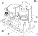
FIG. 4 is a schematic structural view of the drive assembly of the present invention;
FIG. 5 is a schematic structural view of the nail feeding assembly and the nail closing assembly of the present invention;
FIG. 6 is a schematic structural view of the anti-rotation mechanism of the present invention;
FIG. 7 is a schematic structural view of the present invention showing the placement of the tissue clip within the staple cartridge;
FIG. 8 is a schematic view of the structure of the base, middle layer support, top layer support of the present invention;
FIG. 9 is a schematic view showing the construction of the coupling of the outer rotor and the inner rotor according to the present invention;
FIG. 10 is a schematic view of the closure spring of the present invention;
FIG. 11 is a schematic view of the construction of the expanding spring of the present invention;
FIG. 12 is a schematic view of the structure of the housing of the present invention;
FIG. 13 is a schematic structural view of a fourth chuck and a fifth chuck of the present invention;
FIG. 14 is a schematic structural view of a bend control spool of the present invention;
FIG. 15 is a schematic view of the wire fixing device of the present invention;
FIG. 16 is a schematic view of the connection of the wire rope of the present invention to the wire binding device;
FIG. 17 is a schematic view of the construction of the flexible, bendable portion of the clip applier of the invention;
FIG. 18 is a schematic structural view of a joint of the present invention;
FIG. 19 is a schematic view of the construction of the backspacing tether of the present invention;
FIG. 20 is a schematic structural view of the connection of the staple feeding and closing rods to the withdrawal string in accordance with one embodiment of the present invention;
FIG. 21 is a schematic view of a flexible, bendable section of one embodiment of the present invention;
in the drawing, 1 clamp applying clamp, 2 clamp jaws, 3 instrument tube, 4 instrument base, 5 nail feeding rod, 6 nail closing rod, 71 first chuck, 72 first driving wheel, 81 second chuck, 82 second driving wheel, 91 outer rotating body, 911 first column body, 912 cavity, 913 nail feeding driving sleeve, 92 inner rotating body, 921 second column body, 922 nail closing driving sleeve, 93 third column body, 94 third chuck, 95 third driving wheel, 10 gear ring, 11 shell, 111 base, 112 middle layer bracket, 113 upper cover, 114 top layer bracket, 121 rotation stopping tube, 122 first guiding hole, 123 second guiding hole, 124 limiting column, 13 nail bin, 131 limiting bulge, 132 nail bin backstop elastic sheet, 14 nail feeding plate, 141 nail pushing head, 142 nail feeding elastic sheet, 15 closing spring, 16 nail closing spring, 17 nail closing tube, 18 through hole, 19 actuating hook, 191 actuating hook hole, 20 guiding fixing sheet, 201 fixing hole, The device comprises a manual control port 21, a control port cover plate 22, a tissue clamp, an 1 positioning lug boss, central axes of an outer rotator and an inner rotator of the b, a bearing c, a position of a table d and a tail part of a clamping jaw e.
24 front body tube, 25 rear body tube, 26 joints, 261 wire hole, 262 rotating shaft, 27 first straight rod part, 271 front end of nail feeding rod, 28 first snake rod part, 29 second straight rod part, 291 front end of nail closing rod, 30 second snake rod part, 40 withdrawing tensioning rope, 401 withdrawing tensioning rope front end, 50 wire rope, 60 turning control spool, 601 winding shaft groove, 70 wire fixing device, 701 wire hole, 80 fourth chuck and 90 fifth chuck.
Detailed Description
The following examples are given in conjunction with the accompanying drawings to further illustrate the embodiments. The present invention is not limited to the description of the following examples.
In the following embodiments, a main disclosed technical solution is that a repeating clip applier for a surgical robot belongs to a part of a minimally invasive surgical robot system, and is assembled with a mechanical arm during a minimally invasive surgical procedure, and a manipulation action input by a physician (a physician, a nurse or other staff who manipulates the minimally invasive surgical robot system during the surgical procedure) is converted into a surgical action of a front-end instrument through the minimally invasive surgical robot system.
Example 1
In this embodiment, in order to facilitate those skilled in the art to fully and clearly understand the technical solutions disclosed in the embodiments of the present invention, a relatively uniform orientation reference is used: the orientation of the clamping jaw is taken as the front, and the orientation of the body base is taken as the back (refer to figure 1). In this embodiment, the tissue clips may also be referred to as staples or tacks.
Referring to fig. 1 to 4, a continuous emission clip applier for surgical robots, the nail feeding rod, the nail closing rod and the body tube of the clip applier are respectively connected to a body base, which is connected to a robot arm of a surgical robot in use.
As shown in fig. 2, 3 and 4, the body base includes a second transmission component, a third transmission component and a drive assembly. The second transmission component and the third transmission component are respectively connected with the driving assembly.
The second transmission assembly comprises a second chuck and a second transmission wheel, and the second chuck is fixedly connected with the second transmission wheel through a shaft. When the second chuck rotates, the second transmission wheel rotates along with the second chuck.
The third transmission assembly comprises a third chuck and a third transmission wheel, and the third chuck is fixedly connected with the third transmission wheel through a shaft. When the third chuck rotates, the third driving wheel rotates along with the third chuck.
The drive assembly comprises an outer rotor and an inner rotor; the inner rotating body and the outer rotating body can be connected in a rotating mode by taking the central axis of the inner rotating body and the central axis of the outer rotating body as an axis.
As shown in fig. 4, the external rotator includes a first cylindrical body, a cavity extending along a central axis of the first cylindrical body is arranged in the first cylindrical body, and an outer side wall of the first cylindrical body is connected with the third transmission wheel; when the third transmission wheel rotates, the first cylindrical body rotates along with the third transmission wheel.
As shown in fig. 3 and 4, the inner rotating body comprises a second cylindrical body, the upper part of the second cylindrical body extends into the cavity, the lower part of the second cylindrical body is positioned outside the cavity, and the outer side wall of the part of the second cylindrical body, which is positioned outside the cavity, is connected with the second driving wheel; when the second driving wheel rotates, the second cylindrical body rotates along with the second driving wheel; the nail closing driving sleeve is fixedly arranged inside the second cylindrical body, a through screw hole is formed in the middle of the nail closing driving sleeve, and the nail closing rod is in threaded connection with the nail closing driving sleeve.
The one end of keeping away from the open-ended in chamber is fixed to be provided with and send the nail drive cover, send nail drive cover inside to be provided with penetrating screw, send the nail pole with send through threaded connection between the nail drive cover.
The nail feeding rod and the nail closing rod are respectively connected with the rotation stopping mechanism, the rotation stopping mechanism can prevent the nail feeding rod and the nail closing rod from rotating by taking the self central axis as the axis, and the rotation stopping mechanism allows the nail feeding rod and the nail closing rod to move along the self central axis direction.
Preferably, in the embodiment, the nail feeding driving sleeve and the nail closing driving sleeve are hollow sleeve-shaped driving sleeves with connecting threads.
Referring to fig. 8: the upper part of the first cylindrical body is fixedly connected with the positioning seat, and the first cylindrical body can rotate relative to the positioning seat; the lower part of the second cylindrical body is fixedly connected with the other positioning seat, and the second cylindrical body can rotate relative to the positioning seat. It should be clear from reading this embodiment and referring to the drawings that the positioning seat only allows the first cylindrical body and the second cylindrical body to rotate about their own central axes, but does not allow the first cylindrical body and the second cylindrical body to yaw or translate or rotate about their own central axes.
The following illustrates a set of transmission actions: in use, the forceps are used as special forceps for a surgical robot system and are detachably connected with an instrument arm in the surgical robot system. When the rotation stopping mechanism prevents the nail closing rod from rotating and allows the nail closing rod to move along the central axis of the rotation stopping mechanism, so that the nail closing rod moves forwards or backwards. Similarly, when the third chuck rotates forwards or reversely, the third transmission wheel rotates along with the third chuck, so that the first columnar body is driven to rotate, and the nail feeding rod is pushed to move forwards or backwards. In the process of forward movement of the nail feeding rod, the tissue clamp in the nail bin is pushed into the clamping jaw, and the nail closing rod draws the clamping jaw in and closes the clamping jaw when moving forward, so that the tissue clamp is closed.
As shown in fig. 8: the device body base comprises a base, a middle layer bracket and a top layer bracket, wherein the middle layer bracket and the top layer bracket are respectively and fixedly connected with the base; the third cylinder of the burst applicator clamp is rotatably connected to the base. In this embodiment, the structures rotatably coupled to each other are coupled using bearings. The first chuck, the second chuck and the third chuck of the instrument body base respectively extend out of the base, the first chuck, the second chuck and the third chuck are respectively connected with a plurality of brake discs or actuating motors of the surgical robot at corresponding positions, and when the brake discs or the actuating motors rotate forwards or backwards, the first chuck, the second chuck and the third chuck rotate forwards or backwards along with the brake discs or the actuating motors. The body base is provided with a clamping mechanism or other quick-release mechanism for detachably fixing with the surgical robot. In this embodiment, the positioning seats are a base, a middle layer bracket and a top layer bracket respectively.
In some embodiments of the invention, the positioning seat is connected with the first cylindrical body and the second cylindrical body through bearings.
As shown in fig. 9: the inner side wall of the cavity is fixedly connected with the outer side wall of the second cylindrical body through a bearing. The inner diameter of the opening end of the cavity is expanded to form a platform (d), the outer diameter of the upper part of the second cylindrical body is reduced to form a platform, and a bearing is clamped between the platform inside the cavity and the platform outside the second cylindrical body.
As shown in fig. 4 and 9: the nail closing rod is sleeved outside the nail feeding rod, the body pipe is sleeved outside the nail closing rod, and the body pipe, the nail closing rod and the nail feeding rod are coaxially arranged. The nail feeding rod penetrates through the second cylindrical body and is connected with the first cylindrical body.
As shown in fig. 3 and 4: preferably, in some embodiments of the present invention, in order to further enhance the maneuverability of the clip applier, more physician manipulation actions are performed, and the technical solution is optimized: arranging a first transmission assembly and a third cylindrical body, wherein the first transmission assembly comprises a first chuck and a first transmission wheel, and the first chuck is fixedly connected with the first transmission wheel through a shaft; when the first chuck rotates, the first driving wheel rotates along with the first chuck. The lower part of the third cylindrical body is rotatably connected with the positioning seat, the third cylindrical body is fixedly connected with the body tube, and the third cylindrical body is connected with the first transmission wheel. When the first driving wheel rotates, the third columnar body is driven to rotate, and the body pipe follows up. Thereby realizing the autorotation of the body tube of the clip applier. The orientation of the clamping jaw is convenient to adjust. Preferably, the nail feeding rod and the nail closing rod penetrate through the third cylindrical body and are connected with the second cylindrical body and the first cylindrical body.
In the above embodiments, the "positioning seat" described herein is a fixing frame/seat structure having a positioning function and connected to a structure (such as a first cylindrical body, a second cylindrical body, and a third cylindrical body) to be positioned, and on the premise of satisfying compact and precise functions and structural layout, the "positioning seat" may be separate and respectively corresponding to a device structure to be positioned, and may also be an integrated positioning structure.
As shown in fig. 3: the outer side wall of the first columnar body is fixedly provided with a gear ring, the third transmission wheel is a transmission gear, and the gear ring is meshed with the transmission gear; the outer side wall of the second cylindrical body is provided with a gear ring, the second driving wheel is a transmission gear, and the gear ring is meshed with the transmission gear. The outer side wall of the third columnar body is fixedly provided with a gear ring, the first driving wheel is a driving gear, and the gear ring is meshed with the driving gear.
As shown in fig. 5 and 6, preferably, the rotation stopping mechanism comprises a rotation stopping tube, the rotation stopping tube is fixedly connected with the body tube of the clip applier, and the side wall of the rotation stopping tube is provided with a first guide hole;
the side wall of the nail closing rod is provided with a second guide hole corresponding to the first guide hole in position;
the nail feeding rod is fixedly connected with a limiting column, the limiting column is inserted into the first guide hole and the second guide hole, and when the nail feeding rod or the nail closing rod moves towards the front portion or the rear portion of the clip applier, the limiting column moves along the length direction of the first guide hole and the second guide hole. It should be understood from reading the present embodiment that the first guide hole and the second guide hole are holes having a certain length, such as long holes (waist-shaped holes) or other holes capable of limiting the deflection of the position-limiting column and allowing the position-limiting column to move in the length direction. The rotation stopping mechanism can prevent the nail feeding rod and the nail closing rod from rotating along with the rotation of the nail feeding driving sleeve and the nail closing driving sleeve in the rotation process.
As shown in fig. 1, 5 and 7, the clip applier comprises a body tube, a clamping jaw at one end of the body tube, a staple cartridge fixedly arranged in the body tube, a rotation stop tube fixedly arranged in the body tube, a staple feeding assembly for pushing a tissue clip to the clamping jaw, and a staple closing assembly for closing the clamping jaw. The body tube and the nail closing rod are respectively of a hollow structure, the nail closing rod is inserted in the body tube, and the nail feeding rod is inserted in the nail closing rod. The nail feeding assembly comprises a nail feeding rod and a nail feeding plate fixedly connected with the nail feeding rod.
As shown in fig. 10: the clamping jaw is hinged with the front part of the nail bin, and the tail part of the clamping jaw is provided with a closing spring which can provide closing force for the clamping jaw to close for a certain angle.
Referring to figures 5 and 7: the nail bin and the nail feeding plate are inserted into the nail closing pipe, and the nail feeding plate is connected with the nail bin; the front end of the nail feeding plate is provided with a nail pushing head used for pushing the tissue clamp, and when the nail feeding rod moves towards the front end or the rear end of the instrument, the nail feeding plate can move forwards/backwards along the length direction of the nail bin along with the nail feeding rod.
Referring to FIG. 5: preferably, close the nail subassembly including closing the nail pole, close the nail pole suit and send the outside of nail pole, close the front end of nail pole and close nail pipe fixed connection, close nail pipe suit outside the nail storehouse, the lateral wall of nail storehouse is provided with spacing arch, the lateral wall of closing the nail pipe is provided with the via hole, and spacing arch passes from the via hole, and the via hole allows spacing arch to pass through along the length direction of via hole is reciprocal. The via holes are kidney-shaped holes in this embodiment.
As shown in fig. 7, referring to fig. 5, 10, and 11: an opening spring used for keeping the clamping jaws in an opening state is connected to the nail feeding plate. The nail feeding plate is fixedly provided with a nail feeding elastic sheet, the nail bin is internally provided with a nail bin stopping elastic sheet, the nail feeding plate is connected with the nail bin to form a bin which extends along the length direction of the nail bin and can store the tissue clamp, and when the tissue clamp is positioned in the bin, the nail feeding elastic sheet and the nail bin stopping elastic sheet are respectively abutted against a positioning bulge part (also called as a tissue clamp cylinder) of the tissue clamp. The nail feeding elastic sheet and the nail bin backstop elastic sheet are arranged in pairs oppositely. The plurality of tissue clamps are sequentially arranged along the length direction of the nail bin, when the nail feeding rod moves forwards, the nail pushing head feeds the tissue clamp positioned at the forefront position in the nail bin into the clamping jaw, and the nail feeding elastic sheet pushes the tissue clamp positioned at the back position forwards in the process. The tissue clamps are pushed to the clamping jaws one by one and closed, so that the aim of continuously applying the clamps is fulfilled. After the nail feeding is finished once, the nail feeding plate returns backwards, the nail feeding elastic sheet bounces off the tissue clamp under the elastic deformation of the nail feeding elastic sheet in the process, and the nail bin backstop elastic sheet abuts against the positioning bulge of the tissue clamp to prevent the tissue clamp from retreating along with the nail feeding elastic sheet. Before the nail is not fed, the clamping jaw is kept open, the front end of the opening spring is clamped at the tail part of the clamping jaw at the moment, the opening spring moves forwards along with the nail feeding plate until the front end of the opening spring abuts against a boss at the tail part of the clamping jaw, the actuating hook on the opening spring is separated from the actuating hook hole on the nail feeding plate, the nail feeding plate retreats, the actuating hook enters and hooks the actuating hook hole on the nail feeding plate again, the opening spring returns along with the nail feeding plate retreating, and the nail feeding is completed once. When the nail is closed, the nail closing pipe moves forwards until the nail closing pipe closes the clamping jaw collecting cage, and the nail closing is completed.
Referring to fig. 5, a guide fixing piece is fixedly arranged inside the body tube, a fixing hole corresponding to the limiting protrusion is formed in the guide fixing piece, and the limiting protrusion penetrates through the through hole and is inserted into the fixing hole. The guide fixing piece is separated into two parts from the middle part, and the two parts are buckled to form a cylinder shape during assembly. A gap for reciprocating motion of the nail closing tube is preset between the guide fixing piece and the nail bin. The guide fixing piece is welded or clamped and fixed in the inner part of the transformer body tube.
As shown in fig. 4, preferably, the first cylindrical body, the second cylindrical body and the third cylindrical body are coaxially arranged, and the nail closing rod and the nail feeding rod penetrate through a central hole of the third cylindrical body and then extend into the second cylindrical body and the first cylindrical body.
Example 2
As shown in fig. 12, the present embodiment is optimized based on embodiment 1: the shell of the transformer body base comprises an upper cover detachably connected with the base, the upper cover covers the middle layer support and the top layer support inside the transformer body base, a manual control port is formed in the upper cover, and a control port cover plate is detachably connected with the manual control port. The position of the manual control opening corresponds to the position of the second transmission wheel, the third transmission wheel and/or the first transmission wheel inside the base of the machine body.
The control port cover plate is made of transparent materials. The control port cover plate is fixedly clamped with the manual control port.
When the appliance is in power supply loss of a manually irresistible surgical robot system in an accident with extremely low probability, the front-end manipulator appliance cannot move, the clamp applying forceps cannot move, and medical workers can toggle the first transmission wheel, the second transmission wheel and/or the third transmission wheel through the manual control port by opening the control port, so that the method for manually relieving the fault in an emergency condition is provided.
Referring to the drawings, several of the more typical clip application procedures are illustrated below, and the present invention is not limited to a single action among the numerous actions, the following actions being merely exemplary.
In use, the first action is that the body tube rotates: the first chuck drives the first transmission wheel to rotate, the first transmission wheel is meshed with the third cylindrical body through a gear, the third cylindrical body is fixedly connected with the body tube through a pin, and the first chuck rotates to enable the body tube to rotate along the center shaft of the body tube.
And secondly, the feeding clamp is operated, wherein a third chuck is connected with a third driving wheel, the third driving wheel is meshed with a gear outside the first cylindrical body, a nail feeding driving sleeve (also called as a nail feeding nut) is fixed inside the third cylindrical body, and the nail feeding driving sleeve is matched with the screw thread of the nail feeding rod. The nail feeding rod is provided with a limiting column which slides in the long hole of the rotation stopping pipe to prevent the nail feeding rod from rotating. The rotation stopping pipe is fixed in the body pipe through a buckle.
When the third chuck rotates under the driving of the actuating motor/actuating disc, the nail feeding driving sleeve correspondingly rotates, the screw threads push the nail feeding rod, the rotation motion is changed into linear motion, and the nail feeding rod moves forwards or backwards.
The head of the nail feeding rod is fixedly connected with the tail of the nail feeding plate, and the movement of the nail feeding rod is transferred to the nail feeding plate. The head of the staple feeding plate pushes the tissue gripper located in the ready-to-deliver position forward to the working position, at which time the gripper jaws are in an open state. Meanwhile, the nail feeding plate is provided with nail feeding elastic sheets which push a tissue clamp cylinder of a second tissue clamp (the tissue clamp positioned at the forefront part in the nail bin is the first tissue clamp, and the nth tissue clamp is sequentially arranged towards the back part to form the second tissue clamp … …).
Action three, closing the clamp: the second chuck is connected with a second driving wheel which is meshed with a gear outside the second cylindrical body, a nail closing driving sleeve (also called as a nail closing nut) is arranged inside the second cylindrical body, and the nail closing driving sleeve is matched with the screw thread of the nail closing rod. When the second chuck rotates under the drive of the actuating motor/actuating disc, the nail closing driving sleeve correspondingly rotates, the screw threads push the nail closing rod, the rotation motion is changed into linear motion, and the nail closing rod moves forwards along with the linear motion. The rotation stopping mechanism also prevents the nail closing rod from rotating. The head of the nail closing rod is fixedly connected with the tail of the nail closing pipe, and the movement of the nail closing rod is transferred to the nail closing pipe. The nail closing pipe is guided by the guide fixing piece which is fixed in the body pipe through a buckle. And when the nail closing pipe advances, the clamping jaws are pushed to be closed, and the nail closing is completed.
Action four, close the nail pole, send the nail pole to reset: (the related figure shows that the action III is used for closing the clamp), the second chuck rotates reversely (the reverse direction refers to the direction opposite to the direction of the closing nail action) under the driving of the motor, and the closing nail driving sleeve rotates reversely to drive the closing nail rod and the closing nail pipe to return to the original position.
The third chuck rotates reversely under the drive of the motor (the related figure shows that the action II is the nail feeding clamp), the nail feeding driving sleeve rotates reversely, and the nail feeding rod is driven to return to the original position.
In the process that the nail feeding rod drives the nail pushing piece to return to the original position, the head of the nail feeding plate and the nail feeding elastic piece are pulled back, and the second tissue clamp completely returns to the position of preparing the nail bin and is clamped by the nail bin backstop elastic piece.
And fifthly, feeding and closing the nails again: after resetting is completed, feeding the nail again, closing the nail and performing action two: clip feeding and action three: the closed clamp is the same.
Example 3
This example was optimized on the basis of example 2 or 1: as shown in fig. 13 to 20, the shaft of the clip applier has flexible, bendable portions.
As shown in fig. 13, 16 and 18, a bending control spool and a wire fixing device are arranged in the body base, and the wire fixing device is fixedly connected with the middle layer bracket. The two bending control bobbins are fixedly connected with the fourth chuck and the fifth chuck respectively. Two wire ropes with opposite winding directions are fixed on the winding shaft grooves of each turning control spool respectively, the wire ropes enter the body tube through wire holes in the wire fixing device and reach the joints along the body tube and are fixedly connected with the wire rope holes of the joints, and when the turning control spools rotate under the driving of the chucks, the wire ropes drive the joints to turn. Furthermore, two wire ropes on each bending control spool form a group, and each group of wire ropes is connected with two wire rope holes opposite to the phase position of the joint. The fourth chuck and the fifth chuck respectively extend out of the outer side of the base.
In some embodiments of the present invention, two wires are disposed on each of the turning control spools, and the two wires are wound on the turning control spools in opposite directions, that is, when one turning control wire is rotated in one direction along the axis of the turning control spool, one of the two wires is wound along the winding shaft groove toward the turning control spool, and the other wire is gradually wound along the winding shaft groove outward from the turning control spool. After the wire rope is stretched into the body tube from the wire guide hole, the wire rope sequentially penetrates into the wire guide hole on the joint from the rear part of the turning section (the tube section where the joint on the body tube is located is called as the turning section) to the front part of the turning section and is finally fixed with the guide hole of the joint positioned at the forefront part of the turning section. Four wire rope holes are uniformly distributed on the circumference of each joint of the turning section, and two wire ropes on the same turning control spool are respectively connected with two wire rope holes positioned at the diagonal positions in the four wire rope holes, so that the turning of the turning section on one plane is realized.
Referring to figures 19 and 20: the front end of the nail closing rod is fixedly connected with the rear part of the nail closing pipe, and the front end of the nail feeding rod is fixedly connected with the nail feeding plate. In some embodiments of the invention, welding is used for fixing.
Further, the body tube comprises a front body tube and a rear body tube, and the front body tube and the rear body tube are connected through a plurality of joints.
As shown in fig. 18, further, joint bases for fixedly connecting joints are fixedly arranged at the end portions of the front body tube and the rear body tube, adjacent joints are fixedly connected through rotating shafts, two adjacent joints form a turning group, and the axes of the rotating shafts on the adjacent turning groups are perpendicular to each other. In this embodiment, the rotating shaft is a rivet, and adjacent joints can rotate around the rivet. The silk ropes sequentially pass through the silk rope holes in the joints from the back to the front, and the tail end of each silk rope is fixedly connected with the silk rope hole of the joint positioned at the foremost end. As shown in the figure, the nail bin, the nail feeding plate and the guide fixing plate are positioned in the inner part of the front body tube.
Furthermore, the nail feeding rod and the nail closing rod are respectively provided with a flexible part at the position of the joint. The nail feeding rod comprises a first straight rod part and a first snake rod part, and the front end of the nail feeding rod is provided with a front end head. The nail closing rod comprises a second straight rod part and a second snake rod part, and the front end of the nail closing rod is provided with a front end head. The inside fixedly connected with of sending the nail pole backs the taut rope, and the rear portion that backs the taut rope and send the inside fixed connection of nail pole, the front end card of backing the taut rope is put in the draw-in groove of sending the front end of nail pole. The position of the back tensioning rope corresponds to the position of the first snake rod part. When the nail feeding rod moves backwards, the back tension rope can keep tension, and the first snake rod part is prevented from being stretched excessively in the process of backwards moving. Referring to fig. 20, when the clip applier is in the initial state, i.e. the jaws are opened, and the nail feeding rod and the nail closing rod are located at the rearmost part of the movement stroke, the rear end of the front end of the nail feeding rod abuts against the front end of the nail closing rod, and the front end of the withdrawal tension rope is clamped on the front end of the nail feeding rod.
The foregoing is a further detailed description of the invention in connection with specific preferred embodiments and it is not intended to limit the invention to the specific embodiments described. For those skilled in the art to which the invention pertains, several simple deductions or substitutions can be made without departing from the spirit of the invention, and all shall be considered as belonging to the protection scope of the invention.
Claims (10)
1. A burst clip applier for a surgical robot, comprising: the nail feeding rod, the nail closing rod and the instrument body pipe of the clip applier are respectively connected with an instrument body base, and the instrument body base can be connected with a mechanical arm of a surgical robot when in use;
the body base comprises a second transmission component, a third transmission component and a driving assembly;
the second transmission assembly and the third transmission assembly are respectively connected with the driving assembly;
the second transmission assembly comprises a second chuck and a second transmission wheel, and the second chuck is fixedly connected with the second transmission wheel through a shaft; when the second chuck rotates, the second transmission wheel rotates along with the second chuck;
the third transmission assembly comprises a third chuck and a third transmission wheel, and the third chuck is fixedly connected with the third transmission wheel through a shaft; when the third chuck rotates, the third driving wheel rotates along with the third chuck;
the drive assembly includes an outer rotor and an inner rotor; the inner rotating body and the outer rotating body can be connected in a rotating mode by taking the central axis of the inner rotating body and the central axis of the outer rotating body as an axis;
the external rotating body comprises a first cylindrical body, a cavity extending along the central axis of the first cylindrical body is arranged in the first cylindrical body, and the outer side wall of the first cylindrical body is connected with a third driving wheel; when the third transmission wheel rotates, the first cylindrical body rotates along with the third transmission wheel;
the inner rotating body comprises a second cylindrical body, the upper part of the second cylindrical body extends into the cavity, the lower part of the second cylindrical body is positioned outside the cavity, and the outer side wall of the part of the second cylindrical body, which is positioned outside the cavity, is connected with the second driving wheel; when the second driving wheel rotates, the second cylindrical body rotates along with the second driving wheel; a nail closing driving sleeve is fixedly arranged in the second cylindrical body, a through screw hole is formed in the middle of the nail closing driving sleeve, and a nail closing rod is in threaded connection with the nail closing driving sleeve;
one end of the cavity, which is far away from the opening, is fixedly provided with a nail feeding driving sleeve, a through screw hole is formed in the nail feeding driving sleeve, and a nail feeding rod is connected with the nail feeding driving sleeve through threads;
the upper part of the first columnar body is fixedly connected with the positioning seat, and the first columnar body can rotate relative to the positioning seat; the lower part of the second cylindrical body is fixedly connected with the other positioning seat, and the second cylindrical body can rotate relative to the positioning seat;
the nail feeding rod and the nail closing rod are respectively connected with the rotation stopping mechanism, the rotation stopping mechanism can prevent the nail feeding rod and the nail closing rod from rotating by taking the self central axis as the central axis, and the rotation stopping mechanism allows the nail feeding rod and the nail closing rod to move along the self central axis direction.
2. A burst clip applier for a surgical robot according to claim 1, wherein:
the nail closing rod is sleeved outside the nail feeding rod, the body pipe is sleeved outside the nail closing rod, and the body pipe, the nail closing rod and the nail feeding rod are coaxially arranged;
the nail feeding rod penetrates through the second cylindrical body and is connected with the first cylindrical body.
3. A burst clip applier for a surgical robot according to claim 1, wherein: the transmission mechanism comprises a first transmission assembly and a third cylindrical body, wherein the first transmission assembly comprises a first chuck and a first transmission wheel, and the first chuck is fixedly connected with the first transmission wheel through a shaft; when the first chuck rotates, the first transmission wheel rotates along with the first chuck; the lower part of the third cylindrical body is rotatably connected with the positioning seat, the third cylindrical body is fixedly connected with the instrument body tube, the third cylindrical body is connected with the first transmission wheel, and when the first transmission wheel rotates, the third cylindrical body rotates along with the first transmission wheel.
4. A burst clip applier for a surgical robot according to claim 1, wherein: the outer side wall of the first columnar body is fixedly provided with a gear ring, the third transmission wheel is a transmission gear, and the gear ring is meshed with the transmission gear;
the outer side wall of the second cylindrical body is provided with a gear ring, the second driving wheel is a transmission gear, and the gear ring is meshed with the transmission gear.
5. A burst clip applier for a surgical robot according to claim 3, wherein: the outer side wall of the third columnar body is fixedly provided with a gear ring, the first driving wheel is a driving gear, and the gear ring is meshed with the driving gear.
6. A burst clip applier for a surgical robot according to claim 1, wherein: the device body base comprises a base, a middle layer bracket and a top layer bracket, wherein the middle layer bracket and the top layer bracket are respectively and fixedly connected with the base; the third columnar body of the repeating clip applier clamp is rotatably connected with the base; the first chuck, the second chuck and the third chuck of the instrument body base respectively extend out of the base.
7. A burst clip applier for a surgical robot according to claim 1, wherein: the rotation stopping mechanism comprises a rotation stopping pipe, the rotation stopping pipe is fixedly connected with a body pipe of the clip applier, and a first guide hole is formed in the side wall of the rotation stopping pipe;
a second guide hole corresponding to the first guide hole is formed in the side wall of the nail closing rod;
the nail feeding rod is fixedly connected with a limiting column, the limiting column is inserted into the first guide hole and the second guide hole, and when the nail feeding rod or the nail closing rod moves towards the front portion or the rear portion of the clip applier, the limiting column moves along the length direction of the first guide hole and the length direction of the second guide hole.
8. A burst clip applier for a surgical robot according to claim 1, wherein: the tissue clamp comprises a clamping jaw positioned at one end of a body tube, a nail bin fixedly arranged in the body tube, a rotation stopping tube fixedly arranged in the body tube, a nail feeding assembly used for pushing a tissue clamp to the clamping jaw and a nail closing assembly used for closing the clamping jaw;
the nail feeding assembly comprises a nail feeding rod and a nail feeding plate fixedly connected with the nail feeding rod;
the clamping jaw is hinged with the front part of the nail bin, and a closing spring capable of providing closing force for the clamping jaw to close for a certain angle is arranged at the tail part of the clamping jaw;
the nail feeding plate is connected with the nail bin; the front end of the nail feeding plate is provided with a nail pushing head for pushing the tissue clamp, and when the nail feeding rod moves towards the front end or the rear end of the instrument, the nail feeding plate can move forwards/backwards along the length direction of the nail bin along with the nail feeding rod;
and the nail feeding plate is connected with an opening spring.
9. A burst clip applier for a surgical robot according to claim 1, wherein: the nail closing rod in the nail closing assembly of the clip applier is sleeved outside the nail feeding rod, the front end of the nail closing rod is fixedly connected with the nail closing pipe, the nail closing pipe is sleeved outside the nail bin, the side wall of the nail bin is provided with a limiting bulge, the side wall of the nail closing pipe is provided with a through hole, the limiting bulge penetrates through the through hole, and the through hole allows the limiting bulge to pass through in a reciprocating mode along the length direction of the through hole.
10. A burst clip applier for a surgical robot according to claim 1, wherein: a guide fixing piece is fixedly arranged in the instrument body tube, a fixing hole corresponding to the limiting bulge is formed in the guide fixing piece, and the limiting bulge penetrates through the through hole and is inserted into the fixing hole; the guide fixing piece is separated into two parts from the middle part, and the two parts are buckled to form a cylinder shape during assembly; a gap for reciprocating motion of the nail closing tube is preset between the guide fixing piece and the nail bin.
Priority Applications (1)
| Application Number | Priority Date | Filing Date | Title |
|---|---|---|---|
| CN202111427016.7A CN114424960A (en) | 2021-11-28 | 2021-11-28 | Repeating clip applier for surgical robot |
Applications Claiming Priority (1)
| Application Number | Priority Date | Filing Date | Title |
|---|---|---|---|
| CN202111427016.7A CN114424960A (en) | 2021-11-28 | 2021-11-28 | Repeating clip applier for surgical robot |
Publications (1)
| Publication Number | Publication Date |
|---|---|
| CN114424960A true CN114424960A (en) | 2022-05-03 |
Family
ID=81310695
Family Applications (1)
| Application Number | Title | Priority Date | Filing Date |
|---|---|---|---|
| CN202111427016.7A Pending CN114424960A (en) | 2021-11-28 | 2021-11-28 | Repeating clip applier for surgical robot |
Country Status (1)
| Country | Link |
|---|---|
| CN (1) | CN114424960A (en) |
Cited By (1)
| Publication number | Priority date | Publication date | Assignee | Title |
|---|---|---|---|---|
| WO2024249986A1 (en) * | 2023-06-02 | 2024-12-05 | Intuitive Surgical Operations, Inc. | Surgical clip applier instruments with articulating jaws |
-
2021
- 2021-11-28 CN CN202111427016.7A patent/CN114424960A/en active Pending
Cited By (1)
| Publication number | Priority date | Publication date | Assignee | Title |
|---|---|---|---|---|
| WO2024249986A1 (en) * | 2023-06-02 | 2024-12-05 | Intuitive Surgical Operations, Inc. | Surgical clip applier instruments with articulating jaws |
Similar Documents
| Publication | Publication Date | Title |
|---|---|---|
| EP4037577B1 (en) | Articulatable surgical instruments with articulation joints comprising flexible exoskeleton arrangements | |
| US11723666B2 (en) | Flexible surgical stapler | |
| RU2640002C2 (en) | Rotary drive structures for surgical instruments | |
| CN108354668B (en) | Auxiliary robot system for digestive tract operation | |
| CN112672700B (en) | Repeating clip applier and feeding device thereof | |
| US20170340351A1 (en) | Flexible trocar assembly for surgical circular stapling devices | |
| US20230320851A1 (en) | Valve clip delivery device | |
| JP2005218497A (en) | Treating implement for endoscope, endoscope and endoscope treatment system | |
| MXPA01002081A (en) | Surgical suturing instrument and method of use. | |
| CN115530934B (en) | A flexible puncture needle puncture surgical instrument based on wire transmission | |
| CN113616379A (en) | Suture locking and cutting device and suture locking and cutting system | |
| CN114424960A (en) | Repeating clip applier for surgical robot | |
| CN217525261U (en) | Butt joint structure with replaceable components and repeating clamp for surgical robot | |
| CN217525262U (en) | Surgical robot is with running fire of changeable subassembly pincers of executing that can turn | |
| CN114601522A (en) | Continuous shooting clip applier with integrated bendable structure | |
| CN212490258U (en) | Suture locking and cutting device and suture locking and cutting system | |
| CN217525258U (en) | Repeating clip applying forceps for surgical robot | |
| KR101836301B1 (en) | Surgical clamping instrument | |
| CN114191030A (en) | Butt joint structure with replaceable components and repeating clamp for surgical robot | |
| CN217525260U (en) | Bendable repeating clip applier for surgical robot | |
| CN116983087A (en) | Surgical instrument and surgical robot | |
| CN217525259U (en) | Continuous shooting clip applier with integrated bendable structure | |
| CN114424959A (en) | Bendable repeating clip applier for surgical robot | |
| CN114159113A (en) | Surgical robot is with running fire of changeable subassembly pincers of executing that can turn | |
| CN113456141A (en) | Active bending system of anastomat |
Legal Events
| Date | Code | Title | Description |
|---|---|---|---|
| PB01 | Publication | ||
| PB01 | Publication | ||
| DD01 | Delivery of document by public notice | ||
| DD01 | Delivery of document by public notice |
Addressee: Pang Jian Document name: Notice of Termination of Program |
|
| SE01 | Entry into force of request for substantive examination | ||
| SE01 | Entry into force of request for substantive examination |