CN114401646A - Display bar graph and adaptive control - Google Patents
Display bar graph and adaptive control Download PDFInfo
- Publication number
- CN114401646A CN114401646A CN202080064308.6A CN202080064308A CN114401646A CN 114401646 A CN114401646 A CN 114401646A CN 202080064308 A CN202080064308 A CN 202080064308A CN 114401646 A CN114401646 A CN 114401646A
- Authority
- CN
- China
- Prior art keywords
- consumable
- puffs
- usage data
- depletion
- aerosol
- Prior art date
- Legal status (The legal status is an assumption and is not a legal conclusion. Google has not performed a legal analysis and makes no representation as to the accuracy of the status listed.)
- Pending
Links
Images


Classifications
-
- A—HUMAN NECESSITIES
- A24—TOBACCO; CIGARS; CIGARETTES; SIMULATED SMOKING DEVICES; SMOKERS' REQUISITES
- A24F—SMOKERS' REQUISITES; MATCH BOXES; SIMULATED SMOKING DEVICES
- A24F40/00—Electrically operated smoking devices; Component parts thereof; Manufacture thereof; Maintenance or testing thereof; Charging means specially adapted therefor
- A24F40/50—Control or monitoring
- A24F40/53—Monitoring, e.g. fault detection
-
- A—HUMAN NECESSITIES
- A24—TOBACCO; CIGARS; CIGARETTES; SIMULATED SMOKING DEVICES; SMOKERS' REQUISITES
- A24F—SMOKERS' REQUISITES; MATCH BOXES; SIMULATED SMOKING DEVICES
- A24F40/00—Electrically operated smoking devices; Component parts thereof; Manufacture thereof; Maintenance or testing thereof; Charging means specially adapted therefor
- A24F40/50—Control or monitoring
- A24F40/51—Arrangement of sensors
-
- A—HUMAN NECESSITIES
- A24—TOBACCO; CIGARS; CIGARETTES; SIMULATED SMOKING DEVICES; SMOKERS' REQUISITES
- A24F—SMOKERS' REQUISITES; MATCH BOXES; SIMULATED SMOKING DEVICES
- A24F40/00—Electrically operated smoking devices; Component parts thereof; Manufacture thereof; Maintenance or testing thereof; Charging means specially adapted therefor
- A24F40/60—Devices with integrated user interfaces
-
- G—PHYSICS
- G08—SIGNALLING
- G08B—SIGNALLING OR CALLING SYSTEMS; ORDER TELEGRAPHS; ALARM SYSTEMS
- G08B3/00—Audible signalling systems; Audible personal calling systems
- G08B3/10—Audible signalling systems; Audible personal calling systems using electric transmission; using electromagnetic transmission
-
- G—PHYSICS
- G08—SIGNALLING
- G08B—SIGNALLING OR CALLING SYSTEMS; ORDER TELEGRAPHS; ALARM SYSTEMS
- G08B5/00—Visible signalling systems, e.g. personal calling systems, remote indication of seats occupied
- G08B5/22—Visible signalling systems, e.g. personal calling systems, remote indication of seats occupied using electric transmission; using electromagnetic transmission
-
- G—PHYSICS
- G08—SIGNALLING
- G08B—SIGNALLING OR CALLING SYSTEMS; ORDER TELEGRAPHS; ALARM SYSTEMS
- G08B6/00—Tactile signalling systems, e.g. personal calling systems
-
- A—HUMAN NECESSITIES
- A24—TOBACCO; CIGARS; CIGARETTES; SIMULATED SMOKING DEVICES; SMOKERS' REQUISITES
- A24F—SMOKERS' REQUISITES; MATCH BOXES; SIMULATED SMOKING DEVICES
- A24F40/00—Electrically operated smoking devices; Component parts thereof; Manufacture thereof; Maintenance or testing thereof; Charging means specially adapted therefor
- A24F40/20—Devices using solid inhalable precursors
Landscapes
- Physics & Mathematics (AREA)
- Engineering & Computer Science (AREA)
- Human Computer Interaction (AREA)
- General Physics & Mathematics (AREA)
- Electromagnetism (AREA)
- Containers And Packaging Bodies Having A Special Means To Remove Contents (AREA)
- Catching Or Destruction (AREA)
- Infusion, Injection, And Reservoir Apparatuses (AREA)
- Apparatus For Making Beverages (AREA)
- Pharmaceuticals Containing Other Organic And Inorganic Compounds (AREA)
- Nozzles (AREA)
- Medicinal Preparation (AREA)
- Apparatus For Disinfection Or Sterilisation (AREA)
Abstract
披露了一种估计和指示气溶胶产生装置(100)中的消耗品(114)的耗减水平的方法。气溶胶产生装置具有处理器(270)、存储器(241)和状态指示器(201)。该方法包括生成关于使用者使用气溶胶产生装置的使用数据并将该使用数据存储到存储器上的步骤。从存储器读取使用数据,并基于该使用数据来计算耗减水平、优选为消耗品上的剩余抽吸次数方面的耗减水平。将所计算的消耗品的耗减水平和/或消耗品是否已被消耗以信号形式发送到状态指示器。
A method of estimating and indicating a depletion level of a consumable (114) in an aerosol-generating device (100) is disclosed. The aerosol generating device has a processor (270), a memory (241) and a status indicator (201). The method includes the steps of generating usage data regarding the user's use of the aerosol generating device and storing the usage data on a memory. The usage data is read from the memory and based on the usage data a depletion level, preferably a depletion level in terms of the number of puffs remaining on the consumable is calculated. The calculated depletion level of the consumable and/or whether the consumable has been consumed is signaled to the status indicator.
Description
技术领域technical field
本发明涉及一种估计和指示消耗品的耗减水平的方法、一种控制电路系统、以及一种具有处理器、存储器和状态指示器的气溶胶产生装置。The present invention relates to a method of estimating and indicating depletion levels of consumables, a control circuit system, and an aerosol generating device having a processor, a memory and a status indicator.
背景技术Background technique
在过去的几年里,气溶胶产生装置(也称为风险被降低或风险被修正的装置或汽化器)的普及和使用快速增长,这有助于帮助想要戒烟的习惯性吸烟者戒掉诸如香烟、雪茄、小雪茄和卷烟等传统烟草产品。与在常规的烟草产品中灼烧烟草不同,可以获得加热或煽动载体物质来产生供吸入的气溶胶的各种装置和系统。The popularity and use of aerosol-generating devices (also known as risk-reduced or risk-modified devices or vaporizers) has grown rapidly over the past few years, helping to help habitual smokers who want to quit smoking cigarettes such as Traditional tobacco products such as cigarettes, cigars, cigarillos and cigarettes. In contrast to burning tobacco in conventional tobacco products, various devices and systems are available that heat or incite a carrier material to generate an aerosol for inhalation.
一种类型的气溶胶产生装置是加热基质式气溶胶产生装置或加热不灼烧式装置。这种类型的装置通过将固体气溶胶基质(典型地,潮湿的烟叶)加热到可以在150℃到300℃范围内的温度来产生气溶胶。另一种类型的气溶胶产生装置是液体汽化装置。在液体汽化装置中,可以将可汽化物质固持在烟弹中。然后,可以对可汽化物质进行加热或以其他方式(例如,通过振动)对其进行煽动,从而进行气溶胶化。One type of aerosol-generating device is a heated matrix aerosol-generating device or a heat-and-burn device. This type of device produces an aerosol by heating a solid aerosol substrate (typically, moist tobacco leaf) to a temperature that can range from 150°C to 300°C. Another type of aerosol-generating device is a liquid vaporization device. In liquid vaporization devices, the vaporizable substance may be held in the cartridge. The vaporizable substance may then be heated or otherwise agitated (eg, by vibration) to effect aerosolization.
加热但并不燃烧或灼烧气溶胶基质会释放气溶胶,这种气溶胶包括使用者寻求的组分但不包括燃烧产生的有毒和致癌副产物。此外,通过加热气溶胶基质或可汽化物质(例如,烟草)而产生的气溶胶通常不包括由燃烧导致的可能使使用者不愉快的糊味或苦味。这意味着,气溶胶基质不需要通常被添加到常规烟草产品的烟草中以使烟雾对于使用者来说更美味的糖或其他添加剂。然而,与传统香烟相比,使用者无法直接观察气溶胶产生装置中烟草材料的耗减。Heating but not burning or burning the aerosol matrix releases an aerosol that includes the components sought by the user but does not include the toxic and carcinogenic by-products of combustion. Furthermore, aerosols produced by heating an aerosol substrate or a vaporizable substance (eg, tobacco) typically do not include a mush or bitter taste resulting from combustion that may be unpleasant to the user. This means that the aerosol matrix does not require sugar or other additives that are typically added to the tobacco of conventional tobacco products to make the smoke more palatable to the user. However, in contrast to conventional cigarettes, the user cannot directly observe the depletion of tobacco material in the aerosol-generating device.
US 10,143,235披露了一种电子烟个人汽化器。电子烟个人汽化器包括雾化器和抽吸计数器。个人汽化器可以包括一系列12个LED,这些LED随着个人汽化器消耗相当于一支香烟的尼古丁而逐渐亮起。根据US 10,143,235,每次吸入就有一个LED亮起,其中,所使用的电子液体强度意味着吸入十二次对应于吸一支香烟。可替代地,使用者可以将LED设置为使得在消耗了相当于一整支香烟的尼古丁时,单个LED亮起。US 10,143,235 discloses an electronic cigarette personal vaporizer. Electronic cigarette personal vaporizers include atomizers and puff counters. A personal vaporizer may include a series of 12 LEDs that light up gradually as the personal vaporizer consumes the equivalent of a cigarette of nicotine. According to US 10,143,235, one LED lights up for each inhalation, wherein the strength of the e-liquid used means that twelve inhalations correspond to smoking a cigarette. Alternatively, the user may set the LEDs so that a single LED lights up when the equivalent of an entire cigarette has been consumed.
US 2015/0142387 A1披露了一种用于检测、监测和记录与吸烟活动相关的数据的系统。该装置包括壳体、电源、雾化器、以及被配置为位于壳体内的数据记录装置。数据记录装置所包括的微控制器处理记录数据。记录数据包括与系统的特性和状况相关的数据,例如,加热元件、液体储存区域、雾化器、电池和使用者活动记录数据。基于记录数据,微控制器控制向使用者递送的气溶胶有效载荷的量和定时。US 2015/0142387 A1 discloses a system for detecting, monitoring and recording data related to smoking activity. The device includes a housing, a power source, a nebulizer, and a data recording device configured to be located within the housing. A microcontroller included in the data recording device processes the recorded data. Logged data includes data related to the characteristics and conditions of the system, eg, heating elements, liquid storage areas, nebulizers, batteries, and user activity log data. Based on the recorded data, the microcontroller controls the amount and timing of the aerosol payload delivered to the user.
WO 2018/098371 A1涉及一种蒸气吸入系统以及计算机化方法,这种方法用于基于对消费者生理学、消费者体验反馈、消费者使用行为、特定产品和环境因素的动态建模来开发用于治疗和娱乐使用管理的功效的特定于消费者的模型。WO 2018/098371 A1提出使用复杂的多变量感测系统来提高吸用产品的整体功效。WO 2018/098371 A1 relates to a vapor inhalation system and a computerized method for developing an Consumer-specific models of efficacy for therapeutic and recreational use management. WO 2018/098371 A1 proposes to use a complex multivariate sensing system to improve the overall efficacy of an inhalation product.
现有技术的缺点在于,使用者无法在同一时间既有效监测其气溶胶产生装置又根据其需求对该装置进行调整。A disadvantage of the prior art is that the user cannot effectively monitor his aerosol generating device and adjust the device according to his needs at the same time.
发明内容SUMMARY OF THE INVENTION
因此,本发明的目的是提供一种方法、一种控制电路系统以及一种气溶胶产生装置,其允许在简单、直观操纵的同时可根据使用者的习惯、需求和使用情况灵活调整。Therefore, it is an object of the present invention to provide a method, a control circuit system and an aerosol generating device that allow simple and intuitive manipulation while being flexibly adjusted according to the user's habits, needs and usage.
本发明的第一方面涉及一种估计和指示气溶胶产生装置中的消耗品的耗减水平的方法。气溶胶产生装置具有处理器、存储器和状态指示器。该方法包括生成关于使用者使用气溶胶产生装置的使用数据并将该使用数据存储到存储器上的步骤。从存储器读取使用数据,并基于该使用数据来计算耗减水平、优选为消耗品上的剩余抽吸次数。将所计算的消耗品的耗减水平和/或消耗品是否已被消耗以信号形式发送到状态指示器。使用数据可以包括抽吸记录和事件记录,并且该方法可以包括基于事件记录来将抽吸记录分组到时段中的步骤,A first aspect of the present invention relates to a method of estimating and indicating depletion levels of consumables in an aerosol-generating device. The aerosol generating device has a processor, a memory and a status indicator. The method includes the steps of generating usage data regarding the user's use of the aerosol generating device and storing the usage data on a memory. Usage data is read from memory and based on the usage data a depletion level, preferably the number of puffs remaining on the consumable, is calculated. The calculated depletion level of the consumable and/or whether the consumable has been consumed is signaled to the status indicator. The usage data can include puff records and event records, and the method can include the step of grouping puff records into time periods based on the event records,
消耗品可以包括烟草材料部分。烟草材料部分包括例如浸渍有液体气溶胶形成剂或液体气溶胶基质的再造烟草纸的卷起薄片或条。The consumable may include portions of tobacco material. The tobacco material portion includes, for example, a rolled sheet or strip of reconstituted tobacco paper impregnated with a liquid aerosol former or liquid aerosol matrix.
存储器(在本文中有时被称为数据存储单元)可以存储使用数据、尤其是抽吸记录和/或事件记录。数据存储单元可以包括易失性或非易失性存储器,例如,闪速存储器或固态存储器或类似物。数据存储单元可以适合于存储多个抽吸记录或事件记录。在一个示例中,6000个或更多个抽吸记录以及4000个或更多个事件记录可存储在数据存储单元上。如以下将详细解释的,处理器(例如,CPU)可以检索存储在数据存储单元中的全部或部分使用数据,以基于使用者的吸用行为和偏好来计算耗减信号。A memory (sometimes referred to herein as a data storage unit) may store usage data, particularly puff records and/or event records. The data storage unit may include volatile or non-volatile memory, such as flash memory or solid state memory or the like. The data storage unit may be adapted to store multiple aspiration records or event records. In one example, 6000 or more puff records and 4000 or more event records may be stored on the data storage unit. As will be explained in detail below, a processor (eg, a CPU) may retrieve all or part of the usage data stored in the data storage unit to calculate a depletion signal based on the user's smoking behavior and preferences.
该方法的优点在于,以信号形式发送到状态指示器的耗减水平是个性化的,并且根据使用者的需求进行调整。可以计算耗减水平并且将其单独转发给使用者。根据本发明,耗减水平是基于使用行为(即,使用数据)而计算的。因此,将根据使用者的习惯来显示耗减水平。耗减水平可以让使用者知道烟草部分何时耗尽并且必须被更换。The advantage of this approach is that the depletion level signaled to the status indicator is individualized and adjusted according to the needs of the user. The depletion level can be calculated and forwarded individually to the user. According to the present invention, the depletion level is calculated based on usage behavior (ie usage data). Therefore, the depletion level will be displayed according to the user's habits. The depletion level can let the user know when the tobacco portion is exhausted and must be replaced.
例如,高频率的消耗品更换可以指示使用者期望的剂量较高,而低频率的消耗品更换可以指示使用者希望降低其尼古丁摄入。For example, a high frequency of consumable changes may indicate that the user desires a higher dose, while a low frequency of consumable changes may indicate that the user desires to reduce their nicotine intake.
由于耗减水平是基于使用数据而不是现有技术中的固定函数来计算的,因此其更符合使用者的偏好,从而提高了使用者使用气溶胶产生装置的体验。例如,一些用途可能更喜欢强烈的味道,这会导致更快的耗减,而其他使用者可能想要使其烟草部分保留更长的时间。在本发明的示例中,使用者频繁地进行吸用时段,由此推断出,使用者期望更强烈的味道或更多的尼古丁摄入。Since the depletion level is calculated based on usage data rather than a fixed function in the prior art, it is more in line with the user's preference, thereby improving the user's experience of using the aerosol generating device. For example, some uses may prefer a stronger taste, which results in faster depletion, while other users may want to retain their tobacco portion for longer. In the example of the present invention, the user has frequent puff sessions, from which it is inferred that the user desires a stronger taste or more nicotine intake.
在第一方面的优选实施例中,响应于检测到消耗品的插入来计算耗减水平。In a preferred embodiment of the first aspect, the depletion level is calculated in response to detecting the insertion of the consumable.
在第一方面的优选实施例中,使用数据包括以下各项中的至少一项:每个消耗品的抽吸次数;诸如体积、持续时间和/或强度等关于(多次)抽吸的气流的参数;抽吸频率;时段的持续时间和/或频率;以及时段的时间。In a preferred embodiment of the first aspect, the usage data comprises at least one of the following: number of puffs per consumable; airflow with respect to puff(s) such as volume, duration and/or intensity the frequency of puffs; the duration and/or frequency of the session; and the time of the session.
在第一方面的优选实施例中,使用数据包括抽吸记录,这些抽吸记录包括以下各项中的至少一项:关于抽吸气流的参数、以及时间戳。关于气流的参数可以包括抽吸的存在、体积、持续时间和/或强度。In a preferred embodiment of the first aspect, the usage data comprises puff records comprising at least one of: parameters relating to the puff flow, and a time stamp. Parameters related to airflow may include the presence, volume, duration and/or intensity of puffs.
使用数据的进一步参数可以根据抽吸记录来计算并且被用于计算。这种参数的示例是自先前的(多次)抽吸以来所经过的时间、以及时段中的抽吸频率。在某些实施例中,抽吸记录可以另外包括环境数据,即,以下各项中的一项或多项:当前温度、位置和天气。Further parameters of the usage data can be calculated from the aspiration records and used for the calculations. Examples of such parameters are the elapsed time since the previous (multiple) puffs, and the puff frequency in the period. In certain embodiments, the puff record may additionally include environmental data, ie, one or more of the following: current temperature, location, and weather.
在第一方面的优选实施例中,使用数据包括事件记录,这些事件记录包括以下各项中的至少一项:事件类型、消耗品类型、消耗品标识号以及时间戳。事件类型可以包括插入消耗品、移除消耗品、耗尽消耗品、打开气溶胶产生装置(即,打开装置)、关闭气溶胶产生装置以及错误消息。错误消息的示例是加热器故障、(棒)固持器故障、电池电量不足、加热器需要清洁。In a preferred embodiment of the first aspect, the usage data includes event records including at least one of the following: an event type, a consumable type, a consumable identification number, and a time stamp. Event types may include inserting consumables, removing consumables, depleting consumables, turning on the aerosol-generating device (ie, turning on the device), turning off the aerosol-generating device, and error messages. Examples of error messages are heater failure, (rod) holder failure, low battery, heater needs cleaning.
基于这些记录,可以计算进一步指标,诸如连续抽吸之间的时间、时段以及其他抽吸风格指标。时段可以被理解为从激活装置并使用装置直到再次关闭装置的时间。Based on these records, further metrics can be calculated, such as time between successive puffs, periods of time, and other puff style metrics. A period can be understood as the time from when the device is activated and used until the device is turned off again.
在第一方面的优选实施例中,基于事件记录将抽吸记录分组到时段中。特别地,具有在打开气溶胶产生装置的事件的时间戳与关闭气溶胶产生装置的事件的时间戳之间的时间戳的抽吸记录可以被分组到一个时段中。被分组到吸用时段、尤其是最近的或当前的吸用时段中的使用数据可以提供关于当前使用者行为和偏好的可靠信息。In a preferred embodiment of the first aspect, puff records are grouped into time periods based on event records. In particular, puff records with timestamps between the timestamp of the event of opening the aerosol-generating device and the timestamp of the event of closing the aerosol-generating device may be grouped into a period. Usage data grouped into usage periods, especially recent or current usage periods, can provide reliable information about current user behavior and preferences.
时间戳尤其可以包括一天中的时间和/或一周中的某天。在进一步示例中,时间戳可以包括月份和年份。通过以上使用数据,可以分析使用者行为,并且可以基于使用者个人行为来计算准确的个人耗减水平。Timestamps may include, among other things, the time of day and/or the day of the week. In a further example, the timestamp may include month and year. From the above usage data, user behavior can be analyzed and an accurate personal depletion level can be calculated based on the user's personal behavior.
在第一方面的优选实施例中,接收针对所插入消耗品的类型的历程,并且另外基于所插入消耗品的类型来计算剩余抽吸次数。In a preferred embodiment of the first aspect, a history for the type of inserted consumable is received, and the number of puffs remaining is calculated additionally based on the type of inserted consumable.
在第一方面的优选实施例中,耗减水平的计算是基于先前消耗品上的平均抽吸次数。例如,可以通过使用指示消耗品插入到气溶胶产生装置和消耗品从其中移除的事件记录的时间戳根据抽吸记录来获得先前消耗品上的平均抽吸次数。In a preferred embodiment of the first aspect, the calculation of the depletion level is based on the average number of puffs on previous consumables. For example, the average number of puffs on previous consumables can be obtained from puff records by using timestamps of the event records indicating the insertion of the consumable into the aerosol-generating device and the removal of the consumable therefrom.
在第一方面的优选实施例中,耗减水平的计算使用机器学习算法来计算耗减水平。In a preferred embodiment of the first aspect, the calculation of the depletion level uses a machine learning algorithm to calculate the depletion level.
在第一方面的优选实施例中,耗减水平的计算是基于当前时间(尤其是一天中的时间)、紧邻的前一时段上的使用数据和/或当前时段上的使用数据。例如,上午的抽吸可能导致耗减更快,因为它们与晚上(此时抽吸可能不那么强烈)的抽吸相比通常是较深的抽吸。In a preferred embodiment of the first aspect, the calculation of the depletion level is based on the current time (in particular the time of day), usage data over the immediately preceding period and/or usage data over the current period. For example, morning puffs may result in faster depletion because they are generally deeper puffs than evening puffs (when puffs may be less intense).
在第一方面的优选实施例中,耗减水平的计算是基于当前时段上的使用数据与平均时段上的使用数据的比较。In a preferred embodiment of the first aspect, the calculation of the depletion level is based on a comparison of usage data over the current period with usage data over the average period.
在第一方面的优选实施例中,响应于气溶胶产生装置的激活,基于使用数据计算或重新计算耗减水平,其中,该计算或该重新计算优选地基于时间和/或紧邻的前一时段上的使用数据。In a preferred embodiment of the first aspect, the depletion level is calculated or recalculated based on the usage data in response to activation of the aerosol generating device, wherein the calculation or the recalculation is preferably based on time and/or an immediately preceding period usage data on .
在第一方面的优选实施例中,周期性地或响应于检测到抽吸,基于使用数据计算或重新计算耗减水平。该计算或重新计算优选地使用当前时段上的使用数据,并且尤其优选地将该使用数据与先前时段上的使用数据进行比较。In a preferred embodiment of the first aspect, the depletion level is calculated or recalculated based on the usage data periodically or in response to detection of a puff. The calculation or recalculation preferably uses usage data over the current period, and particularly preferably compares the usage data with usage data over previous periods.
在第一方面的优选实施例中,使用以下各项中的至少一项来生成使用数据:抽吸传感器;消耗品更换检测器,尤其是弹出传感器和/或插入传感器;用于检测该消耗品的标识标签的消耗品检测单元;以及使用者输入接口。例如,消耗品更换检测器可以由响应于消耗品的插入而移动的可移动活塞、(末端)位置传感器、接近度传感器、光传感器或开关形成。In a preferred embodiment of the first aspect, the usage data is generated using at least one of the following: a suction sensor; a consumable replacement detector, in particular an eject sensor and/or an insertion sensor; for detecting the consumable The consumable detection unit of the identification label; and the user input interface. For example, the consumable replacement detector may be formed by a movable piston, a (end) position sensor, a proximity sensor, a light sensor or a switch that moves in response to the insertion of a consumable.
抽吸传感器检测抽吸的存在,并且因此可以提供关于以下各项的信息:抽吸长度、(使用时钟来提供)抽吸时间和关于抽吸气流的参数。抽吸传感器可以向处理器提供使用数据。The puff sensor detects the presence of puffs and can therefore provide information on puff length, puff time (provided using a clock) and parameters on puff flow. The puff sensor can provide usage data to the processor.
在第一方面的优选实施例中,使用显示器、扬声器或振动器向使用者指示耗减水平。显示器优选为条形图。由此,可以以图形、听觉或触觉的方式告知使用者消耗品的当前耗减情况。当然,上面提及的状态指示手段可以进行组合。In a preferred embodiment of the first aspect, the depletion level is indicated to the user using a display, speaker or vibrator. The display is preferably a bar graph. Thereby, the user can be informed graphically, audibly or haptically of the current depletion of the consumable. Of course, the above-mentioned status indication means can be combined.
在第一方面的优选实施例中,用具有至少一个发光装置的显示器来指示耗减水平。在优选实施例中,显示器包括两个或更多个发光装置,这些发光装置甚至更优选地以线性布置排列。发光装置可以基于当前耗减情况而改变其颜色。例如,当插入新消耗品时,发光装置可以显示绿色,并且随后根据当前耗减水平而变为红色。In a preferred embodiment of the first aspect, the depletion level is indicated by a display having at least one light emitting device. In a preferred embodiment, the display comprises two or more light emitting devices, which are arranged even more preferably in a linear arrangement. The lighting device can change its color based on the current depletion situation. For example, when a new consumable is inserted, the light emitting device may display green and then turn red according to the current depletion level.
在优选实施例中,显示器包括三个、四个、五个或更多个发光装置(尤其是LED),其中,这些发光装置呈线性布置。线性布置上的进程向使用者显示由处理器计算的烟草材料部分的自适应计算的耗减水平。在具有两个发光装置的示例中,当第一个发光装置亮起时,消耗品的一半已耗尽,并且当第二个发光装置亮起时,消耗品已完全耗尽。可替代地,(多个)发光装置可以具有任何其他合适的布置,诸如可以沿其示出进程的圆。由此,提供了一种用于向使用者显示当前耗减水平的直观且容易的方法。In a preferred embodiment, the display comprises three, four, five or more light emitting devices (especially LEDs), wherein the light emitting devices are arranged in a linear fashion. The progression on the linear arrangement displays to the user the adaptively calculated depletion level of the portion of tobacco material calculated by the processor. In the example with two lighting devices, when the first lighting device is on, half of the consumable is depleted, and when the second lighting device is on, the consumable is completely depleted. Alternatively, the light emitting device(s) may have any other suitable arrangement, such as a circle along which progression may be shown. Thereby, an intuitive and easy method for displaying the current depletion level to the user is provided.
本发明的第二方面涉及一种包括处理器和存储器的控制电路系统。该控制电路系统被配置为执行如上所述的方法。A second aspect of the invention relates to a control circuitry including a processor and a memory. The control circuitry is configured to perform the method as described above.
本发明的第三方面涉及一种具有处理器、存储器和状态指示器的气溶胶产生装置。该气溶胶产生装置被配置为执行如上所述的方法,并借助于状态指示器来指示消耗品的当前耗减水平和/或消耗品是否已被消耗。A third aspect of the invention relates to an aerosol generating device having a processor, a memory and a status indicator. The aerosol generating device is configured to perform the method as described above and to indicate, by means of the status indicator, the current depletion level of the consumable and/or whether the consumable has been consumed.
该气溶胶产生装置可以是加热不灼烧式装置(“T蒸气”)或液体汽化器(“E蒸气”)。在本发明的范围内,加热不灼烧式产品和/或液体汽化器两者均可以被称为气溶胶产生装置。The aerosol generating device may be a heat-and-burn device ("T-vapor") or a liquid vaporizer ("E-vapor"). Within the scope of the present invention, both the heat-not-burn product and/or the liquid vaporizer may be referred to as an aerosol-generating device.
在优选实施例中,气溶胶产生装置包括接口,该接口可以被配置为接纳消耗品,例如,包括电子液体的热棒或烟弹。由于使用者可能难以或无法直接确定热棒或烟弹的耗减水平,因此所提出的当前耗减水平的计算对于包括电子液体的热棒和烟弹尤其有利。In a preferred embodiment, the aerosol-generating device includes an interface that can be configured to receive a consumable, eg, a hot stick or a pod including an e-liquid. Since it may be difficult or impossible for a user to directly determine the depletion level of a hot stick or pod, the proposed calculation of the current depletion level is particularly beneficial for hot sticks and pods that include e-liquids.
参数(例如,消耗品的插入/更换、一天中的时间、消耗品类型(尼古丁、味道)检测等)可以以不同或相同的方式与T蒸气装置和E蒸气装置结合使用。Parameters (eg, insertion/replacement of consumables, time of day, consumable type (nicotine, taste) detection, etc.) can be used in different or identical ways in conjunction with T-vapor devices and E-vapor devices.
在不进行抽吸时,与启用加热时间相关的参数对于T蒸气装置而言可能尤其相关。一个示例可以是两次连续抽吸之间的抽吸间隔和/或持续时间。在T蒸气装置中,加热器在整个吸用时段期间(包括抽吸之间的时间)保持工作于正常运行温度下。烟草部分在抽吸之间可以被加热,并且因此可能影响消耗品的耗减。因此,特别是对于T蒸气装置来说,计算可以考虑加热器的启用时间以及抽吸之间的时间。Parameters related to the time to activate heating may be particularly relevant for T-vapor devices when no puffing is being performed. An example may be the puff interval and/or duration between two consecutive puffs. In a T-vapor device, the heater remains operating at normal operating temperature during the entire puff period, including the time between puffs. The tobacco portion may be heated between puffs and thus may affect depletion of the consumable. Therefore, especially for T-vapor devices, the calculation can take into account the heater activation time and the time between puffs.
在E蒸气装置中,加热器可以由抽吸传感器来激活,并且在抽吸期间加热,但是在不存在抽吸的情况下不加热。抽吸之间不加热,并且抽吸之间的时间可能对耗减水平几乎没有影响。In an E-vapor device, the heater can be activated by a puff sensor and heat up during puff, but not in the absence of puff. There is no heating between puffs, and the time between puffs may have little effect on depletion levels.
消耗品可以包括标识标签,其具有作为计算的基础的默认剩余抽吸次数。在一些实施例中,装置可以包括用于从消耗品的标识标签读取数据的接口。当插入特定类型的消耗品时,默认历程可以允许从更接近使用者偏好的剩余抽吸次数开始计算。The consumable may include an identification label with a default number of puffs remaining as a basis for the calculation. In some embodiments, the device may include an interface for reading data from identification tags of consumables. When inserting a particular type of consumable, the default course may allow counting from a number of puffs remaining closer to the user's preference.
在优选实施例中,默认剩余抽吸次数基于消耗品的类型。可以有不同类别的消耗品(例如,具有不同共混物的消耗品或具有诸如甲醇、香草和水果调味剂等添加剂的消耗品),使用者可以基于其个人偏好来进行选择。装置可以根据标识标签来检测消耗品的类别,并且相应地调整默认抽吸次数。根据尤其优选的选项,使用者可以能够在消耗品或装置上设置其优选的默认水平。在进一步优选实施例中,使用者可以通过接口(例如,一个或多个按钮)来提供默认抽吸次数。In a preferred embodiment, the default number of puffs remaining is based on the type of consumable. There may be different categories of consumables (eg, consumables with different blends or consumables with additives such as methanol, vanilla, and fruit flavors) that users can choose based on their personal preferences. The device can detect the category of the consumable from the identification tag and adjust the default number of puffs accordingly. According to a particularly preferred option, the user may be able to set his preferred default level on the consumable or device. In a further preferred embodiment, the user may provide a default number of puffs through an interface (eg, one or more buttons).
附图说明Description of drawings
在下文中,参考附图中所示的实施例以示例性方式进一步详细描述本发明,在附图中:In the following, the invention is described in further detail by way of example with reference to embodiments shown in the accompanying drawings, in which:
图1:是根据第一实施例的气溶胶产生装置的示意性透视图,其中示出的是消耗品正被装入气溶胶产生装置中,Figure 1: is a schematic perspective view of an aerosol-generating device according to a first embodiment, wherein consumables are shown being loaded into the aerosol-generating device,
图2:是图1的气溶胶产生装置和消耗品从侧面的示意性截面视图,Figure 2: is a schematic cross-sectional view of the aerosol generating device and consumables of Figure 1 from the side,
图3:是气溶胶产生装置的第二实施例的示意性透视图,Figure 3: is a schematic perspective view of a second embodiment of the aerosol generating device,
图4a、图4b、图4c:是在使用气溶胶产生装置期间一系列耗减水平的示意性视图,Figures 4a, 4b, 4c: are schematic views of a series of depletion levels during use of an aerosol generating device,
图5:是在使用气溶胶产生装置期间一系列事件的示意性视图,Figure 5: is a schematic view of a sequence of events during the use of an aerosol generating device,
图6:是气溶胶产生装置的部件的框图,Figure 6: is a block diagram of the components of the aerosol generating device,
图7:是气溶胶产生装置所包括的控制电路系统的框图,Figure 7: is a block diagram of the control circuit system included in the aerosol generating device,
图8:是插入消耗品后的耗减水平的自适应计算的流程图,Figure 8: is a flowchart of the adaptive calculation of the consumption level after inserting consumables,
图9:是开始新的吸用时段后的耗减水平的自适应计算的流程图,Figure 9: is a flowchart of the adaptive calculation of the depletion level after starting a new intake period,
图10:是吸用时段期间的耗减水平的自适应计算的流程图,Figure 10: is a flow chart of adaptive calculation of depletion levels during the intake period,
图11A和图11B:是插入/弹出传感器的第一实施例的示意性视图,11A and 11B : are schematic views of the first embodiment of the insertion/ejection sensor,
图11C和图11D:是插入/弹出传感器的第二实施例的示意性视图,以及11C and 11D : are schematic views of a second embodiment of an insert/eject sensor, and
图12A至图12C:是插入/弹出传感器的第三实施例的示意性视图。12A to 12C: are schematic views of a third embodiment of an insertion/ejection sensor.
具体实施方式Detailed ways
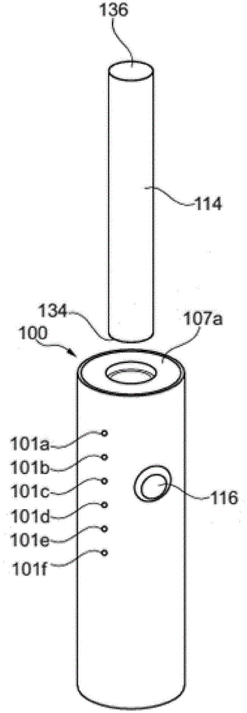
图1和图2示出了气溶胶产生装置100和被实现为基质载体114的消耗品。气溶胶产生装置100包括容纳气溶胶产生装置100的各种部件的本体118。如图1和图2所示,本体118为管状和圆柱状。应注意,本体118不必具有管状或圆柱形形状,而是可以具有任何形状,只要其尺寸适应本文阐述的各种实施例中所描述的部件即可。本体118可以由任何合适的材料或者材料层形成。例如,本体118的外壳可以由金属制成的内层和塑料制成的外层形成。这允许本体118让使用者愉快地握住。1 and 2 illustrate an aerosol-generating
本体118包括第一端104和第二端106。在使用中,使用者通常将气溶胶产生装置100定向成使得第一端104朝下和/或相对于使用者的嘴处于远侧位置,并且第二端106朝上和/或相对于使用者的嘴处于近侧位置。第二端106通过与本体118的内部部分的过盈配合来固持一对垫圈107a、107b(参见图2的截面)。气溶胶产生装置100包括用于接纳基质载体114的接口,其中,该接口被实现为朝向气溶胶产生装置100的第二端106定位的加热腔室108。加热腔室108朝向气溶胶产生装置100的第二端106开放,并且可以将基质载体114接纳至加热腔室108内。The
进一步地,装置100具有使用者可操作的按钮116。按钮116位于本体118上。按钮116被布置成使得在例如通过按下按钮来致动时,使用者可以激活气溶胶产生装置100并开始吸用时段。激活后,可以加热基质载体114以产生供吸入的气溶胶。在本体118的侧壁上,装置100进一步包括状态指示器,该状态指示器被实现为包括发光装置101a至101f的显示器101。发光装置101a-f沿本体118的轴线线性排列。Further, the
加热腔室108(参见图2)包括开口端110、侧壁126和底座112。在侧壁126的内表面上形成多个突出物140。突出物140朝向基质载体114延伸并与其接合。Heating chamber 108 (see FIG. 2 ) includes
在图中所示的实施例中,气溶胶产生装置100是电动的。气溶胶是通过气溶胶产生装置100使用电功率而产生的。气溶胶产生装置100具有电力电源120,例如,电池。电源120联接到控制电路系统122,该控制电路系统可操作地连接到加热器124。使用者可操作的按钮被布置为在致动时经由控制电路系统122将电源122与加热器124联接。进一步地,控制电路系统122控制发光装置101a-f。In the embodiment shown in the figures, the
图1和图2中结合气溶胶产生装置100而示出的基质载体114包括第一端134和第二端136。载体114包括烟草部分。在载体114的情况下,部分烟草是朝向第一端134布置的气溶胶基质128(参见图4)和朝向第二端136布置的蒸气收集部130。蒸气收集部130和气溶胶基质128两者均由包裹物132固持。The
气溶胶基质和基质载体114可以被称为消耗品或可消耗物品。在所展示的实施例中,可消耗物品可以呈含有加工过的烟草材料的棒形式,例如,浸渍有液体气溶胶形成剂的再造烟草(RTB)纸的卷起薄片或定向条。The aerosol matrix and
使用者从第一端134开始将基质载体114插入到加热腔室108中,直到第一端134接触到底座112。在该位置,加热器124可操作以加热基质128,从而产生气溶胶。气溶胶产生装置100包括用于检测基质载体114的插入和移除的末端位置传感器(例如,活塞,未示出)。The user inserts the
使用者通过按压对控制电路系统122和电源122进行控制的按钮116来激活装置100,从而向电加热器124供应电功率。按钮116可以包括用于指示气溶胶产生装置100的当前状态的一个或多个灯(例如,一个或多个LED或其他合适的光源)。该状态可以指以下各项中的一项或多项:电池剩余电量、耗减水平、加热器状态(尤其是开、关、错误等)、装置状态(例如,准备进行抽吸)或其他状态指示,例如,错误模式。The user activates the
使用者可以将载体114插入到加热腔室108中。当插入载体114时,可移动活塞(未示出)可以响应于载体114的插入而移动,并向处理器发送插入信号。可替代地或另外,装置100可以包括用于检测载体114的不同的传感器,诸如位置传感器、接近度传感器、光传感器或开关。控制电路系统可以检测来自传感器的信号,并且可以生成事件记录,即,载体114的插入。另一方面,当移除载体114时,控制电路系统可以检测来自传感器的第二信号,并且可以生成第二事件记录,即,载体114的移除。事件记录存储在数据存储单元上,从而可以立即或稍后对其进行处理。The user may insert the
控制电路系统122可以被配置为对抽吸进行计数。使用者的单次吸入可以被称为一次“抽吸”。控制电路系统122可以被配置为对抽吸进行计数,即,通过接收来自抽吸传感器的信号来对抽吸进行计数。在一些实施例中,装置使用温度传感器来确定抽吸的存在。温度在抽吸期间会降低,因为新鲜的冷空气流过温度传感器,并且因此,温度下降可以指示抽吸。在其他实施例中,控制电路系统可以使用气流传感器(未示出)来确定通过装置100或通过气溶胶产生基质128的气流。
控制电路系统122包括如图7所示的处理器270。处理器270控制具有发光装置101a-f的显示器101(和/或按钮116中的类似的附加发光装置)。显示器101向使用者显示基质载体114的当前耗减水平。
例如,基质载体可以允许60次抽吸。在图1和图2所示的示例中,显示器101包括6个发光装置101a-f。因此,在前十次抽吸之后,第一个发光装置101a被激活。在进一步的十次抽吸之后,第二个发光装置101b被激活,而第一个发光装置101a可以保持激活,或者可以不保持激活。在消耗了全部60次抽吸之后,激活最后一个发光装置101f,这向使用者指示基质载体114的气溶胶基质128耗尽并且需要更换基质载体114。For example, the matrix carrier can allow 60 suctions. In the example shown in Figures 1 and 2, the
图3中示出了具有吸嘴50和显示器60的气溶胶产生装置100的第二实施例的示意性视图。气溶胶产生装置100包括具有条形图60的本体118。条形图60包括细长区段61至66,其中的每个区段均包括LED。这些区段之一(区段64)被激活。这指示,即,耗减了50%的烟草部分(6个区段中的3个区段)。细长区段61至66是间隔开的。有利地,细长区段61至66也可以被布置为直接与彼此相邻。A schematic view of a second embodiment of an aerosol-generating
图4a、图4b和图4c中示出了发光装置101的第三实施例的示意性视图。在第三实施例中,状态指示器被实现为显示器101,该显示器示出了其长度随着消耗品的消耗而减小的条。在图4a中,基质载体114刚刚插入,并且状态指示器示出了尚未发生耗减。在图4b中,耗减了约50%的基质载体,而在图4c中,基质载体耗减了95%。图4a、图4b和图4c中所示的连续显示器101允许对耗减水平进行微调。Schematic views of a third embodiment of a
为了改善使用者体验,装置100可以具有内部存储的不同历程。在第一种模式(预编程模式)下,该装置包括被实现为电子存储器的数据存储装置,该电子存储器可以是控制电路系统122的一部分,其上内部存储有不同的历程。第一历程(“高强度”)对应于高强度。在该历程下,图1中的第一个发光装置101a在前五次抽吸之后亮起。然后,第二个发光装置101b在抽吸次数等于10时亮起。因此,在30次抽吸(6个发光装置乘以5次抽吸)之后就已经达到了耗尽。该历程对于进行深吸(这导致基质载体114快速耗减)的使用者可能特别有利。To improve the user experience, the
可以选择的第二历程(“中等强度”)在8次抽吸之后从一个发光装置(例如,发光装置101a)过渡到下一个光会议装置(例如,发光装置101b)。在该历程下,基质载体在48次抽吸之后耗尽。第三历程(“低强度”)可能适合于在每次抽吸期间仅在装置上短促地和/或轻轻地抽吸的使用者。在第三历程下,在12次抽吸之后完成从一个发光装置到下一个发光装置的过渡。使用者可以通过按压按钮(例如,按钮116)来在历程之间切换。A second course ("moderate intensity") that can be selected transitions from one lighting device (eg,
可替代地或另外,过渡之间的抽吸次数可以由基质载体来确定。例如,每个基质载体114可以包括标识标签,例如,RFID标签、条形码、或基质载体上的可以由装置100读出的任何信息。基质载体或其他消耗品(尤其是具有液体气溶胶产生基质的烟弹)可以包括电子存储器作为标识标签。在从标识标签读出信息之后,装置100的控制电路系统122切换到适当的历程。消耗品可以例如具有不同的尼古丁量或味道。通过这些历程,可以根据特定类型的消耗品对耗减水平进行调整。Alternatively or additionally, the number of puffs between transitions can be determined by the matrix carrier. For example, each
在第二种模式(自适应模式)下,可以根据使用者的需要而对装置进行个性化处理。在第二种模式下,不是像在第一种模式下那样针对每种消耗品或每种类型的消耗品使用固定不变的进程,而是基于使用者的行为自适应地计算发光装置101之间的进程。抽吸传感器对在所插入的每个消耗品上执行的抽吸次数进行计数,这为客户个人提供了关于该客户认为该部分何时耗尽的信息。根据该信息,计算显示器101的进程。例如,如果使用者规律地或平均地在54次抽吸之后替换基质载体114,则在9次抽吸之后可能发生从一个发光装置到下一个发光装置的过渡。In the second mode (adaptive mode), the device can be personalized according to the user's needs. In the second mode, instead of using a fixed process for each consumable or each type of consumable as in the first mode, the
在该模式下,装置检测新消耗品的引入,并跟踪计数器CT1。当插入新消耗品时,处理器将计数器CT1重置为零。当装置被激活时,该装置监测抽吸并对其进行计数,这使得CT1相应增加(即,每抽吸一次加一)。当装置关闭时,抽吸次数被存储在数据存储单元中。In this mode, the device detects the introduction of new consumables and keeps track of the counter CT1. When a new consumable is inserted, the processor resets the counter CT1 to zero. When the device is activated, the device monitors and counts puffs, which causes CT1 to increase accordingly (ie, one for each puff). When the device is turned off, the number of puffs is stored in the data storage unit.
该过程的一个简化示例如图5所示。图5示出了在以插入新消耗品开始到以弹出该消耗品结束的时间范围内可能发生的不同事件。第一时间线(参见图5顶部,“消耗品检测”)指示对消耗品的插入和弹出的检测。第二时间线(参见图5中部,“抽吸序列”)指示使用者进行的抽吸,并且第三时间线(参见图5底部)指示打开装置100的时期(“吸用时段”)。A simplified example of this process is shown in Figure 5. Figure 5 illustrates the different events that may occur in the time frame starting with the insertion of a new consumable and ending with the ejection of the consumable. The first timeline (see top of Figure 5, "Consumable Detection") indicates detection of insertion and ejection of consumables. The second timeline (see middle of FIG. 5, "puff sequence") indicates the puffs performed by the user, and the third timeline (see bottom of FIG. 5) indicates the period during which the
装置100检测到消耗品的插入10。然后,装置100在时刻20被激活,直到使用者在时刻22关闭该装置。在此第一吸用时段21期间,使用者进行了四次抽吸12。装置100将这4次抽吸存储在电子存储器中。在稍后的第三时刻24,使用者重新激活该装置并开始第二吸用时段25。在第二时段25中,使用者进行了四次抽吸14,然后再次关闭该装置。此后,检测到消耗品的弹出30。The
使用者在使用消耗品期间总共进行了8次抽吸,然后其才认为该消耗品已耗尽。当插入下一个消耗品时,装置可以根据在图5所示的时段中收集的信息来显示耗减水平。例如,在第一次抽吸之后,显示器的第一部分(发光装置101a)亮起;在第三次抽吸之后,显示器101的第二部分(发光装置101b)亮起,依此类推。状态指示器(显示器101)根据使用者在前一时段中的消耗来示出耗减水平。The user takes a total of 8 puffs while using the consumable before he considers the consumable to be depleted. When the next consumable is inserted, the device may display the depletion level based on the information collected during the period shown in FIG. 5 . For example, after the first puff, the first part of the display (light emitting
另外,处理器可以将消耗先前消耗品时进行的抽吸次数与进一步历史数据(即,在所消耗的另外的消耗品上的抽吸次数)进行比较。处理器可以运行算法以调整和确定通常在这种消耗品上进行的抽吸次数。该算法可以包括一般的统计分析或诸如机器学习(包括神经网络)等更复杂的统计分析。Additionally, the processor may compare the number of puffs performed while consuming the previous consumable with further historical data (ie, the number of puffs on additional consumables consumed). The processor may run algorithms to adjust and determine the number of puffs typically performed on such consumables. The algorithm may include general statistical analysis or more complex statistical analysis such as machine learning (including neural networks).
本发明不限于在使用消耗品期间对抽吸总次数进行计数。以类似的方式,可以考虑抽吸频率以及吸用时段21和25的长度,或本文提及的任何其他使用数据。在一个示例中,消费者比平时更频繁地进行连续的吸用时段,这可能指示其期望有更多或更强烈的味道或尼古丁摄入。因此,单个消耗品上的总消耗可以减少到16次抽吸,而不是使用者通常进行的20次抽吸。The present invention is not limited to counting the total number of puffs during use of the consumable. In a similar manner, the puff frequency and length of
在另一示例中,对于新消耗品,消费者每15秒进行一次抽吸,而在先前的消耗品上,消费者每30秒进行一次抽吸,这也可能指示期望有更强烈的味道或尼古丁摄入。以类似的方式,通过相应地计算耗减水平,可以将总消耗减少到20到16次抽吸。In another example, a consumer puffs every 15 seconds for a new consumable, while on a previous consumable the consumer puffs every 30 seconds, which may also indicate a desire for a stronger flavor or Nicotine intake. In a similar fashion, the total consumption can be reduced to 20 to 16 puffs by calculating the depletion level accordingly.
进一步地,装置100可以包括时钟,该时钟记录一天中的时间以及使用者在这一天中的该时间期间的吸用行为。例如,在上午,使用者可能会开始较短的吸用时段,且抽吸频繁,而在下午,同一使用者会开始较长的吸用时段,且抽吸不频繁。在这种情况下,消耗品在上午耗减得更快,而在下午则耗减得更慢。Further, the
处理器可以每次将状态指示器重置为0%(即,消耗了0%,所有发光装置均未点亮)或100%(剩余百分之一百可供消耗,所有发光装置均点亮或最后一个发光装置点亮)。尽管图1至图4c以线性形式或条形图示出了发光装置101a-f(尤其是LED)的进程,但本发明不限于这种状态指示器。另外或可替代地,该装置可以包括显示数值的显示器、一圈发光装置、或具有任意数量的发光装置的条形图。耗减水平可以示出为沿图(尤其是条形图或圆形图)的进程、数字、闪烁频率、颜色或其任何组合。例如,发光装置101a可以发出绿光,而发光装置101c可以发出橙光,并且发光装置101f可以发出红光。The processor can reset the status indicator to 0% each time (ie, 0% consumed, all lights unlit) or 100% (one hundred percent remaining for consumption, all lights on) or the last light-emitting device lights up). Although Figures 1 to 4c illustrate the progression of the
图6示出了气溶胶产生装置200(例如,图1至图4c之一所示的气溶胶产生装置100)的框图。然而,图6方框图中所示的单元也可以在诸如基于电子液体的装置等其他气溶胶产生装置中实施。气溶胶产生装置200包括控制电路系统222,其将耗减信号发送到向使用者报告耗减水平的状态指示器201。Figure 6 shows a block diagram of an aerosol-generating device 200 (eg, the aerosol-generating
控制电路系统从使用数据传感器251至253和时钟254收集数据,并基于该数据计算耗减水平。由控制电路系统接收的任何数据都可以保存在数据存储单元240中。从使用传感器251至253收集的数据也可以直接存储在数据存储单元中。数据存储装置可以包括基于从传感器251至253收集的使用数据的所插入的每个消耗品的耗减历程。可以在稍后阶段分析这种耗减历程,以自适应地估计耗减水平(尤其参见图8至图10)。Control circuitry collects data from
从弹出传感器251、抽吸传感器252、消耗品识别单元253和时钟254收集数据。弹出传感器251用于检测消耗品从装置的弹出或移除。消耗品识别单元253被配置为识别所插入的消耗品并检索/读取指示该消耗品的尼古丁水平、味道或其他相关特性的数据。Data is collected from the
气溶胶产生装置200可以包括用户界面260。用户界面可以接收使用者进行设置的输入,和/或在默认计算耗尽信号与自适应计算耗尽信号之间切换。进一步地,用户界面可以接收使用者操纵耗减水平或其计算的输入。Aerosol-generating
气溶胶产生装置200可以包括另外的传感器,诸如适于测量外界温度或气溶胶产生装置200的加热器温度的温度传感器、惯性运动传感器或倾斜传感器。在自适应计算使用者行为时还可以考虑另外的传感器的数据。The aerosol-generating
当弹出传感器向控制电路系统发送指示消耗品插入到气溶胶产生装置或从气溶胶产生装置中弹出的信号时,控制电路系统生成事件记录,该事件记录具有包括消耗品的插入或弹出以及消耗品的插入时间的条目。另外,控制电路系统可以计算上一次插入/弹出之间的时间,并将结果添加至事件记录。此后,消耗品识别单元253可以检测诸如RFID标签或电子存储器等标识标签,并读取其上包含的标识数据。可以将标识数据添加至事件记录,或者可以添加单独的附加事件记录。例如,控制电路系统可能已经生成具有以下条目的事件记录:时间:星期四,2019年5月8日,20:15;插入新烟弹;烟弹类型为“强”。数据存储单元240可以包括关于检测到的特定烟弹类型的进一步数据,诸如尼古丁浓度、特定香味或合适的加热器温度。可替代地,这种进一步数据可以包含在标识数据中。When the eject sensor sends a signal to the control circuitry indicating that the consumable is inserted into or ejected from the aerosol-generating device, the control circuitry generates an event record that includes the insertion or ejection of the consumable and the consumable the entry at the insertion time. Additionally, the control circuitry can calculate the time between the last insert/eject and add the result to the event log. Thereafter, the
当使用者在香烟上抽吸时,抽吸传感器252检测到抽吸,并且控制电路系统添加抽吸记录。与事件记录类似,可以将由时钟254测量的时间添加至抽吸记录。取决于传感器数据,可以将附加数据添加至抽吸记录。例如,抽吸传感器可以检测和测量气流,控制电路系统或抽吸传感器本身可以根据该气流来计算抽吸体积。控制电路系统可以计算抽吸记录的进一步条目。特别地,控制电路系统可以计算前一次抽吸与当前抽吸之间的时间,将一系列抽吸一起分组到某个吸用时段,并将抽吸记录链接至任何先前事件记录或其条目。可以基于装置打开的阶段和/或以其他方式将抽吸分组到时段中。控制电路系统可以将所有的事件记录和抽吸记录存储到数据存储单元240上,并访问数据存储单元240来读出事件记录和抽吸记录以进行自适应计算。When the user puffs on the cigarette,
图7详细示出了控制电路系统222。控制电路系统包括处理器270、功率控制器260、显示控制器280和内部数据存储单元241。图6所示的数据存储单元240可以被实现为内部数据存储单元241或外部数据存储单元242,其中可以保存所有记录。控制电路系统可以包括输入接口271至273,如例如图6所示的各种传感器、用户界面和单元可以连接到这些输入接口。进一步地,控制电路系统包括到电池的连接275和到加热器的连接276。加热器由功率控制器260控制。由控制电路系统222获得的任何数据都可以保存在控制电路系统222所包括的内部数据存储单元241中或者外部数据存储单元242中。进一步地,控制电路系统包括用于向状态指示器201发送耗减信号的接口277。FIG. 7 shows the
图8至图10的流程图进一步详细示出了耗减水平的自适应计算。图8示出了插入新消耗品后的耗减水平的自适应计算。首先,激活装置。激活之后,使用者可以插入新消耗品。先前提及的弹出传感器可以检测消耗品的插入,并向控制电路系统发送相应的信号。然后,控制电路系统可以使用默认值或检索进一步的数据,诸如先前插入和弹出的消耗品的事件记录以及先前的抽吸记录。基于抽吸记录、事件记录和一天中的当前时间,控制电路系统可以计算并设置剩余抽吸次数(例如,30次抽吸后,所插入的消耗品将耗尽),并向使用者示出当前耗减水平(例如,100%或30次抽吸后将耗尽)。每当抽吸传感器检测到抽吸时,都会更新剩余抽吸次数,直到消耗品耗尽。然后,弹出传感器可以检测到消耗品的移除。在随后插入新消耗品之后,控制电路系统可以基于所检索的先前吸烟时段的数据重新计算耗尽抽吸次数,并将耗尽抽吸次数设置为相同或不同的数量。例如,使用者可能已经进行了指示高摄入和快速耗减的快且深的抽吸,这可能导致控制电路系统为后续消耗品设置较低的耗尽抽吸次数(例如,28或27次抽吸后将耗尽)。The flowcharts of Figures 8-10 illustrate the adaptive calculation of the depletion level in further detail. Figure 8 shows an adaptive calculation of the depletion level after inserting a new consumable. First, activate the device. After activation, the user can insert new consumables. The previously mentioned eject sensor can detect the insertion of a consumable and send a corresponding signal to the control circuitry. The control circuitry can then use the default values or retrieve further data, such as event records for previously inserted and ejected consumables and previous puff records. Based on puff records, event records, and the current time of day, the control circuitry can calculate and set the number of puffs remaining (eg, after 30 puffs, the inserted consumable will be depleted), and display to the user Current depletion level (eg, 100% or depletion after 30 puffs). The number of puffs remaining is updated each time the puff sensor detects a puff, until the consumable is exhausted. The ejection sensor can then detect the removal of the consumable. After subsequent insertion of the new consumable, the control circuitry may recalculate the number of exhausting puffs based on the retrieved data from the previous puff session and set the number of exhausting puffs to the same or a different number. For example, the user may have performed fast and deep puffs indicative of high intake and rapid depletion, which may cause the control circuitry to set a lower number of depleted puffs (eg, 28 or 27) for subsequent consumables will be exhausted after aspiration).
图9示出了耗减水平的另一自适应计算的流程图。在图9中,剩余抽吸次数的自适应计算通过开始新的吸用时段来触发。当使用者激活装置时,开始新的时段。开始新的吸用时段与插入新消耗品的不同之处在于,继续使用先前插入的且部分耗尽的消耗品。因此,剩余抽吸次数/耗减水平开始于较低的值。Figure 9 shows a flow diagram of another adaptive calculation of depletion levels. In Figure 9, the adaptive calculation of the number of puffs remaining is triggered by starting a new puff period. When the user activates the device, a new session begins. Starting a new draw session differs from inserting a new consumable in that a previously inserted and partially depleted consumable continues to be used. Therefore, the remaining puffs/depletion level starts at a lower value.
当开始新的时段时,控制电路系统可以仅使用为前一时段计算的耗减水平,或者其可以例如基于在前一时段期间所测得的耗减情况来计算更新的耗减水平。例如,控制电路系统可能检测到现在是晚上,而前一时段是在上午,因此会重新计算耗减水平。通常,如上所述,以与图8中的上述示例类似的方式计算剩余抽吸次数(即,耗减水平),并向使用者示出耗减水平。When starting a new period, the control circuitry may only use the depletion level calculated for the previous period, or it may calculate an updated depletion level, eg, based on the measured depletion during the previous period. For example, the control circuitry may detect that it is evening and the previous period was in the morning, and thus recalculate the depletion level. Typically, as described above, the number of puffs remaining (ie, the depletion level) is calculated in a manner similar to the above-described example in Figure 8, and the depletion level is shown to the user.
图10示出了另一自适应计算。在图10的实施例中,每当抽吸传感器检测到抽吸时,就会触发自适应计算。当控制电路系统生成新的抽吸记录时,从剩余抽吸次数中扣除一次抽吸。如上面所提及的,控制电路系统检索数据,并通过额外考虑检索到的数据所指示的(先前的)使用者行为来计算剩余抽吸次数。Figure 10 shows another adaptive calculation. In the embodiment of Figure 10, the adaptive computation is triggered whenever a puff is detected by the puff sensor. When the control circuitry generates a new puff record, one puff is subtracted from the number of puffs remaining. As mentioned above, the control circuitry retrieves the data and calculates the remaining number of puffs by additionally taking into account the (previous) user behavior indicated by the retrieved data.
在以上实施例中,可以从数据存储装置检索数据,或者将数据直接发送到处理器并用于计算。In the above embodiments, the data can be retrieved from the data storage, or sent directly to the processor and used for computation.
图8至图10中所示的自适应计算可以单独使用或以任何组合使用。优选地,同时使用图8至图10中所示的所有自适应计算。在以上示例中,耗减水平的自适应计算通过诸如打开装置、插入消耗品或抽吸等事件来触发。自适应计算不一定要被触发,并且还可以在设定的时间范围内持续更新。The adaptive calculations shown in Figures 8-10 may be used alone or in any combination. Preferably, all adaptive calculations shown in Figures 8-10 are used simultaneously. In the above example, the adaptive calculation of the depletion level is triggered by events such as turning on the device, inserting a consumable, or puffing. Adaptive calculations do not have to be triggered and can also be continuously updated within a set time frame.
图11A至图12C示出了插入/弹出传感器的不同实施例的示意图。这些附图示出了气溶胶产生装置的接纳热棒的部分。气溶胶产生装置可以与图1至图3中所示的装置100类似。以简化形式示出的气溶胶产生装置100包括接纳消耗品114的接口108(即,加热腔室)。在接口内,提供了朝向断开位置偏置的开关301。开关301经由连接导线302、303连接到控制电路系统。当消耗品通过开口端110被推入接口108中时,消耗品114的第一端134会使开关301闭合,从而接通电路(参见图11B)。因此,检测到消耗品114的插入。当移除消耗品114时,开关301再次断开。由此,检测到消耗品114的移除。11A-12C show schematic diagrams of different embodiments of insertion/ejection sensors. These figures show the portion of the aerosol-generating device that receives the hot rod. The aerosol-generating device may be similar to the
图11C和图11D中示出了这种插入/弹出传感器的变体。类似于图11A和图11B中所示的开关301,披露了开关305。开关305朝向断开位置偏置,并通过连接导线306和307连接到控制电路系统。然而,开关305被布置在接口108的末端部分处,并且只有在消耗品114已被完全插入时才会闭合。因此,只有在使用者已将消耗品114推入其末端位置(如图11D所示)时才会检测到插入。Variations of this insertion/ejection sensor are shown in Figures 11C and 11D. Similar to switch 301 shown in FIGS. 11A and 11B ,
图12A至图12C中示出了插入/弹出传感器的进一步变体。在该实施例中,接口108中布置有活塞310。活塞朝向接口的开口端偏置。当活塞处于图12A中所示的位置(即,处于第一位置)时,连接导线312和313的开关311处于闭合位置。一旦使用者插入消耗品114(如图12B中的箭头315所示),活塞310就被推离开口端110。这将断开开关311并且使得能够检测到消耗品114的插入。Further variations of the insertion/ejection sensor are shown in Figures 12A-12C. In this embodiment, a
图12A至图12C中所示的实施例另外包括具有枢轴317的杠杆316。杠杆316可绕枢轴旋转并致动活塞311。当使用者致动杠杆317(如箭头318所指示的那样)时,消耗品114被推出接口108(如箭头319所指示的那样)。致动杠杆316会使导线313与312之间通过开关311进行电接触,并且使得能够检测到消耗品114的弹出。The embodiment shown in FIGS. 12A-12C additionally includes a
Claims (16)
Applications Claiming Priority (3)
| Application Number | Priority Date | Filing Date | Title |
|---|---|---|---|
| EP19198018 | 2019-09-18 | ||
| EP19198018.4 | 2019-09-18 | ||
| PCT/EP2020/076139 WO2021053165A1 (en) | 2019-09-18 | 2020-09-18 | Display bar graph and adaptive control |
Publications (1)
| Publication Number | Publication Date |
|---|---|
| CN114401646A true CN114401646A (en) | 2022-04-26 |
Family
ID=67997476
Family Applications (1)
| Application Number | Title | Priority Date | Filing Date |
|---|---|---|---|
| CN202080064308.6A Pending CN114401646A (en) | 2019-09-18 | 2020-09-18 | Display bar graph and adaptive control |
Country Status (7)
| Country | Link |
|---|---|
| US (1) | US20220346458A1 (en) |
| EP (2) | EP4406437A3 (en) |
| JP (2) | JP7556944B2 (en) |
| KR (1) | KR20220062525A (en) |
| CN (1) | CN114401646A (en) |
| PL (1) | PL4030950T3 (en) |
| WO (1) | WO2021053165A1 (en) |
Cited By (1)
| Publication number | Priority date | Publication date | Assignee | Title |
|---|---|---|---|---|
| CN113925229A (en) * | 2021-11-25 | 2022-01-14 | 深圳市吉迩科技有限公司 | Nebulizer and aerosol generating device |
Families Citing this family (18)
| Publication number | Priority date | Publication date | Assignee | Title |
|---|---|---|---|---|
| CN111772239B (en) * | 2020-06-30 | 2025-03-18 | 惠州市吉瑞科技有限公司 | A disposable electronic cigarette with large puff count and control method thereof |
| KR102547780B1 (en) * | 2020-10-27 | 2023-06-26 | 주식회사 케이티앤지 | Apparatus for removing sidestream smoke and control method thereof |
| KR102586969B1 (en) * | 2021-02-08 | 2023-10-06 | 주식회사 케이티앤지 | Aerosol generating device |
| US20220269763A1 (en) * | 2021-02-19 | 2022-08-25 | Medda, Inc. | Tailoring administration of aerosolized bioactive material |
| KR20220161084A (en) * | 2021-05-28 | 2022-12-06 | 주식회사 케이티앤지 | Aerosol generating device comprising puff recognition function and method thereof |
| GB202109226D0 (en) * | 2021-06-25 | 2021-08-11 | Nicoventures Trading Ltd | An aerosol provision system |
| GB202109219D0 (en) * | 2021-06-25 | 2021-08-11 | Nicoventures Trading Ltd | An aerosol provision system |
| US20240284985A1 (en) * | 2021-06-30 | 2024-08-29 | Philip Morris Products S.A. | Aerosol-generating device with progress indication |
| EP4418923A4 (en) * | 2021-10-19 | 2025-08-13 | Kt & G Corp | AEROSOL GENERATING DEVICE AND METHOD FOR OPERATING THE SAME |
| CN114241729B (en) * | 2021-12-13 | 2023-06-20 | 中国人民解放军陆军工程大学 | A vibration shock alarm device |
| CN114365871B (en) * | 2022-01-27 | 2025-06-20 | 惠州市新泓威科技有限公司 | Anti-counterfeiting electronic cigarette with limited service life and control method thereof |
| WO2024017595A1 (en) * | 2022-07-20 | 2024-01-25 | Philip Morris Products S.A. | Aerosol-generating device and aerosol-delivery system |
| GB202215580D0 (en) * | 2022-10-21 | 2022-12-07 | Nicoventures Holdings Ltd | Aerosol provision device |
| EP4642271A1 (en) * | 2022-12-30 | 2025-11-05 | KT&G Corporation | Aerosol generating device |
| US20240289425A1 (en) * | 2023-02-27 | 2024-08-29 | Njoy, Llc | Electronic vaping devices, cartridges, and access control systems |
| WO2024260755A1 (en) * | 2023-06-22 | 2024-12-26 | Jt International Sa | An aerosol generating article and an aerosol generating system |
| WO2025046699A1 (en) * | 2023-08-28 | 2025-03-06 | 日本たばこ産業株式会社 | Aerosol generation device |
| CN117859964A (en) * | 2024-01-26 | 2024-04-12 | 深圳市吉迩科技有限公司 | Atomizing device, control method of atomizing device, and computer-readable storage medium |
Citations (8)
| Publication number | Priority date | Publication date | Assignee | Title |
|---|---|---|---|---|
| CN1719989A (en) * | 2002-11-28 | 2006-01-11 | 英美烟草(投资)有限公司 | Smoking behaviour analyser |
| US20130319435A1 (en) * | 2010-12-24 | 2013-12-05 | Philip Morris Products Sa | Aerosol generating system having means for handling consumption of a liquid subtrate |
| CN204377920U (en) * | 2014-12-19 | 2015-06-10 | 中国烟草总公司广东省公司 | A kind of tobacco juice storage is known and with the homogeneity cigarette of smoke generating device |
| CN106102811A (en) * | 2013-11-21 | 2016-11-09 | 方特慕控股第四私人有限公司 | Device, method and system for recording smoking data |
| US20170027229A1 (en) * | 2015-07-28 | 2017-02-02 | Lunatech, Llc | Inhalation puff counter gauge and display system |
| CN107397255A (en) * | 2016-05-19 | 2017-11-28 | 上海烟草集团有限责任公司 | The atomizer information transferring method of atomizer and electronic cigarette |
| CN108135287A (en) * | 2015-11-17 | 2018-06-08 | 菲利普莫里斯生产公司 | Aerosol generation system with self-excitation electric heater |
| KR20180070440A (en) * | 2016-12-16 | 2018-06-26 | 주식회사 케이티앤지 | Aerosol generating apparatus and method for providig function of limiting smoking thereof |
Family Cites Families (35)
| Publication number | Priority date | Publication date | Assignee | Title |
|---|---|---|---|---|
| US6803545B2 (en) * | 2002-06-05 | 2004-10-12 | Philip Morris Incorporated | Electrically heated smoking system and methods for supplying electrical power from a lithium ion power source |
| US7164993B2 (en) * | 2002-08-08 | 2007-01-16 | Plowshare Technologies, Inc. | Method for measuring smoking topography |
| US9743691B2 (en) * | 2010-05-15 | 2017-08-29 | Rai Strategic Holdings, Inc. | Vaporizer configuration, control, and reporting |
| RS62384B1 (en) * | 2010-08-24 | 2021-10-29 | Jt Int Sa | Inhalation device including substance usage controls |
| US9078473B2 (en) * | 2011-08-09 | 2015-07-14 | R.J. Reynolds Tobacco Company | Smoking articles and use thereof for yielding inhalation materials |
| GB201413019D0 (en) | 2014-02-28 | 2014-09-03 | Beyond Twenty Ltd | Beyond 1B |
| WO2016082077A1 (en) * | 2014-11-24 | 2016-06-02 | 惠州市吉瑞科技有限公司 | Atomizer component, electronic cigarette having limited lifespan, and method for limiting lifespan of electronic cigarette |
| KR102755161B1 (en) | 2014-12-05 | 2025-01-15 | 쥴 랩스, 인크. | Calibrated dose control |
| GB201517086D0 (en) * | 2015-09-28 | 2015-11-11 | Nicoventures Holdings Ltd | Electronic vapour provision system |
| CA3009923A1 (en) | 2016-02-19 | 2017-08-24 | Philip Morris Products S.A. | Aerosol-generating system with usage determination |
| US9936734B2 (en) | 2016-03-11 | 2018-04-10 | Altria Client Services, Llc. | Personal carrying case for electronic vaping device |
| US11147315B2 (en) | 2016-07-25 | 2021-10-19 | Fontem Holdings 1 B.V. | Controlling an operation of an electronic cigarette |
| TWI613971B (en) * | 2016-09-01 | 2018-02-11 | 新唐科技股份有限公司 | Anti-counterfeit electric vaporization device, system and anti-counterfeit method |
| CA3044299A1 (en) | 2016-11-23 | 2018-05-31 | Cloudmode Corp. | Integrated distributed classification, prediction and response system |
| US10834967B2 (en) | 2016-12-27 | 2020-11-17 | Gofire, Inc. | System and method for managing concentrate usage of a user |
| US10551935B2 (en) * | 2017-04-07 | 2020-02-04 | University Of South Carolina | Wearable computing device featuring machine-learning-based smoking detection |
| CN111685394A (en) * | 2017-04-11 | 2020-09-22 | 韩国烟草人参公社 | Aerosol generating device, method of providing feedback, and computer-readable recording medium |
| CN110494053B (en) * | 2017-04-11 | 2022-05-31 | 韩国烟草人参公社 | Aerosol generating device |
| GB201707050D0 (en) | 2017-05-03 | 2017-06-14 | British American Tobacco Investments Ltd | Data communication |
| TWI787316B (en) * | 2017-09-08 | 2022-12-21 | 瑞士商菲利浦莫里斯製品股份有限公司 | Aerosol-generating device, non-transitory computer readable storage medium and method of identifying a consumable |
| GB201716730D0 (en) * | 2017-10-12 | 2017-11-29 | British American Tobacco Investments Ltd | Aerosol provision systems |
| WO2019104223A1 (en) | 2017-11-22 | 2019-05-31 | Juul Labs, Inc. | Electronic vaporizer sessioning |
| WO2019129843A1 (en) * | 2017-12-29 | 2019-07-04 | Jt International Sa | Heating assembly for a vapour generating device |
| JP3215509U (en) * | 2018-01-04 | 2018-03-29 | スリー・アールシステム株式会社 | Battery for electronic cigarette and electronic cigarette |
| US20190217027A1 (en) * | 2018-01-17 | 2019-07-18 | Indose Inc | Device for vaporized substance dosage metering based on an input dosage |
| GB201803027D0 (en) | 2018-02-26 | 2018-04-11 | Nerudia Ltd | Apparatus and method for component lifetime monitoring in a network-enabled smoking substitute device |
| CA3096955A1 (en) | 2018-03-14 | 2019-09-19 | Canopy Growth Corporation | Vape devices, including cartridges, tablets, sensors, and controls for vape devices, and methods for making and using the same |
| JP3216735U (en) * | 2018-03-20 | 2018-06-21 | スリー・アールシステム株式会社 | Battery for electronic cigarette and electronic cigarette |
| GB201807497D0 (en) | 2018-05-08 | 2018-06-20 | Nicoventures Trading Ltd | An aerosol provision device |
| EP4268642A3 (en) | 2018-05-30 | 2023-12-27 | Philip Morris Products S.A. | Detection of adverse heater conditions in an electrically heated aerosol generating system |
| US20200146361A1 (en) | 2018-11-09 | 2020-05-14 | Pax Labs, Inc. | Vaporizing related data protocols |
| EP3711584A1 (en) | 2019-03-22 | 2020-09-23 | Nerudia Limited | Smoking substitute system |
| US12389950B2 (en) | 2019-04-02 | 2025-08-19 | Paxlabs, Inc. | Fixed dose cartridge for vaporizer device |
| JP7253052B2 (en) | 2019-07-03 | 2023-04-05 | 日本たばこ産業株式会社 | Method of operating suction device power supply unit, suction device power supply unit and computer readable medium |
| CN112438437B (en) | 2019-09-03 | 2022-12-20 | 深圳市合元科技有限公司 | Aerosol generating system, aerosol detecting method, atomizing device, and power supply device |
-
2020
- 2020-09-18 CN CN202080064308.6A patent/CN114401646A/en active Pending
- 2020-09-18 JP JP2022514516A patent/JP7556944B2/en active Active
- 2020-09-18 PL PL20774977.1T patent/PL4030950T3/en unknown
- 2020-09-18 KR KR1020227008570A patent/KR20220062525A/en not_active Abandoned
- 2020-09-18 WO PCT/EP2020/076139 patent/WO2021053165A1/en not_active Ceased
- 2020-09-18 US US17/761,028 patent/US20220346458A1/en active Pending
- 2020-09-18 EP EP24181706.3A patent/EP4406437A3/en active Pending
- 2020-09-18 EP EP20774977.1A patent/EP4030950B1/en active Active
-
2024
- 2024-09-11 JP JP2024157804A patent/JP2024167429A/en active Pending
Patent Citations (8)
| Publication number | Priority date | Publication date | Assignee | Title |
|---|---|---|---|---|
| CN1719989A (en) * | 2002-11-28 | 2006-01-11 | 英美烟草(投资)有限公司 | Smoking behaviour analyser |
| US20130319435A1 (en) * | 2010-12-24 | 2013-12-05 | Philip Morris Products Sa | Aerosol generating system having means for handling consumption of a liquid subtrate |
| CN106102811A (en) * | 2013-11-21 | 2016-11-09 | 方特慕控股第四私人有限公司 | Device, method and system for recording smoking data |
| CN204377920U (en) * | 2014-12-19 | 2015-06-10 | 中国烟草总公司广东省公司 | A kind of tobacco juice storage is known and with the homogeneity cigarette of smoke generating device |
| US20170027229A1 (en) * | 2015-07-28 | 2017-02-02 | Lunatech, Llc | Inhalation puff counter gauge and display system |
| CN108135287A (en) * | 2015-11-17 | 2018-06-08 | 菲利普莫里斯生产公司 | Aerosol generation system with self-excitation electric heater |
| CN107397255A (en) * | 2016-05-19 | 2017-11-28 | 上海烟草集团有限责任公司 | The atomizer information transferring method of atomizer and electronic cigarette |
| KR20180070440A (en) * | 2016-12-16 | 2018-06-26 | 주식회사 케이티앤지 | Aerosol generating apparatus and method for providig function of limiting smoking thereof |
Cited By (1)
| Publication number | Priority date | Publication date | Assignee | Title |
|---|---|---|---|---|
| CN113925229A (en) * | 2021-11-25 | 2022-01-14 | 深圳市吉迩科技有限公司 | Nebulizer and aerosol generating device |
Also Published As
| Publication number | Publication date |
|---|---|
| EP4406437A3 (en) | 2024-10-30 |
| WO2021053165A1 (en) | 2021-03-25 |
| KR20220062525A (en) | 2022-05-17 |
| JP2024167429A (en) | 2024-12-03 |
| EP4030950B1 (en) | 2024-07-24 |
| JP7556944B2 (en) | 2024-09-26 |
| PL4030950T3 (en) | 2024-12-16 |
| EP4030950C0 (en) | 2024-07-24 |
| US20220346458A1 (en) | 2022-11-03 |
| EP4030950A1 (en) | 2022-07-27 |
| EP4406437A2 (en) | 2024-07-31 |
| JP2022548524A (en) | 2022-11-21 |
Similar Documents
| Publication | Publication Date | Title |
|---|---|---|
| CN114401646A (en) | Display bar graph and adaptive control | |
| KR102773870B1 (en) | Aerosol generating system with usage mode determination function | |
| KR102010105B1 (en) | Aerosol generating system with consumption monitoring and feedback | |
| CN111726996A (en) | Aerosol generating device and control method thereof | |
| CN114766739A (en) | Aerosol generating device and method providing adaptive feedback based on puff identification | |
| HK1251978A1 (en) | Non-combustion type flavor inhaler and atomization unit | |
| TW202042664A (en) | Aerosol generating device and operation method thereof | |
| US20220218022A1 (en) | Smoking substitute component | |
| EA042372B1 (en) | BAR DISPLAY DEVICE AND ADAPTIVE CONTROL | |
| JP7245311B2 (en) | suction device | |
| CA3125568A1 (en) | Vaporizer mouthpiece | |
| EP3794993A1 (en) | Smoking substitute component | |
| EP3794981A1 (en) | Smoking substitute component | |
| EP3794983A1 (en) | Smoking substitute component | |
| EP4449921A2 (en) | Smoking substitute component | |
| EP3794994A1 (en) | Smoking substitute component | |
| WO2023046503A1 (en) | Aerosol delivery component | |
| WO2021053107A1 (en) | Smoking substitute component | |
| HK1198241B (en) | Aerosol generating system with consumption monitoring and feedback | |
| NZ624139B2 (en) | Aerosol generating system with consumption monitoring and feedback |
Legal Events
| Date | Code | Title | Description |
|---|---|---|---|
| PB01 | Publication | ||
| PB01 | Publication | ||
| SE01 | Entry into force of request for substantive examination | ||
| SE01 | Entry into force of request for substantive examination | ||
| WD01 | Invention patent application deemed withdrawn after publication |
Application publication date: 20220426 |
|
| WD01 | Invention patent application deemed withdrawn after publication |