CN114397998B - Pattern recognition method, pattern recognition model training method, device and equipment - Google Patents
Pattern recognition method, pattern recognition model training method, device and equipment Download PDFInfo
- Publication number
- CN114397998B CN114397998B CN202210298581.6A CN202210298581A CN114397998B CN 114397998 B CN114397998 B CN 114397998B CN 202210298581 A CN202210298581 A CN 202210298581A CN 114397998 B CN114397998 B CN 114397998B
- Authority
- CN
- China
- Prior art keywords
- node
- input operations
- nodes
- feature
- edge
- Prior art date
- Legal status (The legal status is an assumption and is not a legal conclusion. Google has not performed a legal analysis and makes no representation as to the accuracy of the status listed.)
- Active
Links
Images


Classifications
-
- G—PHYSICS
- G06—COMPUTING OR CALCULATING; COUNTING
- G06F—ELECTRIC DIGITAL DATA PROCESSING
- G06F3/00—Input arrangements for transferring data to be processed into a form capable of being handled by the computer; Output arrangements for transferring data from processing unit to output unit, e.g. interface arrangements
- G06F3/01—Input arrangements or combined input and output arrangements for interaction between user and computer
- G06F3/048—Interaction techniques based on graphical user interfaces [GUI]
- G06F3/0487—Interaction techniques based on graphical user interfaces [GUI] using specific features provided by the input device, e.g. functions controlled by the rotation of a mouse with dual sensing arrangements, or of the nature of the input device, e.g. tap gestures based on pressure sensed by a digitiser
- G06F3/0488—Interaction techniques based on graphical user interfaces [GUI] using specific features provided by the input device, e.g. functions controlled by the rotation of a mouse with dual sensing arrangements, or of the nature of the input device, e.g. tap gestures based on pressure sensed by a digitiser using a touch-screen or digitiser, e.g. input of commands through traced gestures
- G06F3/04883—Interaction techniques based on graphical user interfaces [GUI] using specific features provided by the input device, e.g. functions controlled by the rotation of a mouse with dual sensing arrangements, or of the nature of the input device, e.g. tap gestures based on pressure sensed by a digitiser using a touch-screen or digitiser, e.g. input of commands through traced gestures for inputting data by handwriting, e.g. gesture or text
-
- G—PHYSICS
- G06—COMPUTING OR CALCULATING; COUNTING
- G06N—COMPUTING ARRANGEMENTS BASED ON SPECIFIC COMPUTATIONAL MODELS
- G06N3/00—Computing arrangements based on biological models
- G06N3/02—Neural networks
- G06N3/04—Architecture, e.g. interconnection topology
- G06N3/045—Combinations of networks
-
- G—PHYSICS
- G06—COMPUTING OR CALCULATING; COUNTING
- G06N—COMPUTING ARRANGEMENTS BASED ON SPECIFIC COMPUTATIONAL MODELS
- G06N3/00—Computing arrangements based on biological models
- G06N3/02—Neural networks
- G06N3/08—Learning methods
Landscapes
- Engineering & Computer Science (AREA)
- Theoretical Computer Science (AREA)
- Physics & Mathematics (AREA)
- General Engineering & Computer Science (AREA)
- General Physics & Mathematics (AREA)
- General Health & Medical Sciences (AREA)
- Computing Systems (AREA)
- Computational Linguistics (AREA)
- Data Mining & Analysis (AREA)
- Evolutionary Computation (AREA)
- Biomedical Technology (AREA)
- Molecular Biology (AREA)
- Biophysics (AREA)
- Artificial Intelligence (AREA)
- Life Sciences & Earth Sciences (AREA)
- Mathematical Physics (AREA)
- Software Systems (AREA)
- Health & Medical Sciences (AREA)
- Human Computer Interaction (AREA)
- Information Retrieval, Db Structures And Fs Structures Therefor (AREA)
Abstract
The application provides a pattern recognition method, a pattern recognition model training device and a pattern recognition model training device, belongs to the technical field of artificial intelligence, and can be applied to vehicle-mounted scenes. The method comprises the following steps: acquiring sequence characteristics of a plurality of input operations based on the plurality of input operations on the input device; obtaining node features and edge features of a graph network based on the graph network representing a plurality of input operations; acquiring first category information and second category information based on the sequence characteristics, the node characteristics and the edge characteristics; and displaying at least one graph corresponding to the plurality of input operations based on the first category information and the second category information. According to the scheme, the track sequence characteristics capable of accurately describing the input operation are introduced on the basis of the node characteristics and the edge characteristics, so that the graph corresponding to the input operation is determined on the basis of the sequence characteristics, the node characteristics and the edge characteristics, the recognition capability of a single graph can be improved, and the accuracy in recognizing the flow chart with few graphs is improved.
Description
Technical Field
The present application relates to the field of artificial intelligence technologies, and in particular, to a pattern recognition method, a pattern recognition model training method, an apparatus, and a device.
Background
The standardization process of the hand-drawn graph refers to a process of quickly and accurately restoring the graph written by the user, such as identifying and standardizing a flow chart, a thinking guide chart, a topological graph and the like written by the user to obtain a standardized graph which can be deleted, changed and moved. How to accurately identify the hand-drawn graph has important research value.
Disclosure of Invention
The embodiment of the application provides a graph recognition method, a graph recognition model training device and graph recognition model training equipment. The technical scheme is as follows.
In one aspect, a method for pattern recognition is provided, the method comprising:
acquiring sequence characteristics of a plurality of input operations on an input device, wherein the sequence characteristics are used for representing differences between adjacent sampling points in tracks of the input operations;
based on a graph network representing the plurality of input operations, obtaining node features and edge features of the graph network, wherein the nodes in the graph network are used for representing the tracks of the plurality of input operations, and the edges in the graph network are used for representing space-time relations among the tracks of the plurality of input operations, and the space-time relations comprise at least one of input time adjacency or space position adjacency;
acquiring first category information and second category information based on the sequence feature, the node feature and the edge feature, wherein the first category information is used for representing a category to which a track of an input operation belongs, the second category information is used for representing a category to which an inter-track relationship belongs, and the inter-track relationship is used for representing whether the tracks of two input operations belong to the same graph or not;
displaying at least one graph corresponding to the plurality of input operations based on the first category information and the second category information.
In another aspect, a method for training a pattern recognition model is provided, the method including:
inputting tracks of a plurality of sample input operations into a pattern recognition model to obtain first prediction information and second prediction information, wherein the first prediction information is used for indicating the types of track predictions of the plurality of sample input operations, the second prediction information is used for representing the types of relationship predictions among the tracks, and the relationship among the tracks is used for representing whether the tracks of two sample input operations belong to the same pattern;
determining a first loss and a second loss based on the first prediction information, the second prediction information and a label graph corresponding to the tracks of the plurality of sample input operations, wherein the first loss represents a loss of a category to which the predicted track belongs, and the second loss represents a loss of a category to which the inter-track relationship is predicted to belong;
training the pattern recognition model based on the first loss and the second loss.
In another aspect, there is provided a pattern recognition apparatus, the apparatus including:
the device comprises a first acquisition module, a second acquisition module and a third acquisition module, wherein the first acquisition module is used for acquiring sequence characteristics of a plurality of input operations on an input device, and the sequence characteristics are used for representing differences between adjacent sampling points in tracks of the input operations;
the first obtaining module is further configured to obtain node features and edge features of a graph network representing the plurality of input operations, where nodes in the graph network are used to represent trajectories of the plurality of input operations, and edges in the graph network are used to represent spatiotemporal relationships between the trajectories of the plurality of input operations, where the spatiotemporal relationships include at least one of input temporal adjacency or spatial position adjacency;
a second obtaining module, configured to obtain first category information and second category information based on the sequence feature, the node feature, and the edge feature, where the first category information is used to indicate a category to which a trajectory of an input operation belongs, the second category information is used to indicate a category to which an inter-trajectory relationship belongs, and the inter-trajectory relationship is used to indicate whether trajectories of two input operations belong to a same graph;
and the display module is used for displaying at least one graph corresponding to the plurality of input operations based on the first category information and the second category information.
In some embodiments, the first obtaining module is configured to sample the trajectories of the multiple input operations to obtain a sampling point sequence, where the sampling point sequence includes multiple sampling points; for any group of adjacent sampling points in the sampling point sequence, acquiring a transverse offset, a longitudinal offset and a continuity identifier between the adjacent sampling points, wherein the continuity identifier is used for indicating whether the adjacent sampling points belong to the same input operation; determining sequence characteristics of the plurality of input operations based on a plurality of sets of adjacent sample points in the sequence of sample points.
In some embodiments, the apparatus further comprises:
a graph network construction module for constructing nodes in the graph network based on the trajectory geometric attributes, trajectory positions and spatiotemporal relations among the trajectories of the plurality of input operations; and constructing edges in the graph network among nodes corresponding to the tracks based on the space-time relation among the tracks.
In some embodiments, the first obtaining module is configured to determine the node feature based on a geometric feature, a location feature, and a context feature of a trajectory of an input operation represented by a node in the graph network, where the context feature is used to represent a spatiotemporal relationship between trajectories of the input operation; the edge features are determined based on spatiotemporal relationships between trajectories of input operations represented by edge-connected nodes in the graph network.
In some embodiments, the second obtaining module includes:
a first obtaining unit, configured to obtain trajectory features of the plurality of input operations based on the sequence features;
a second obtaining unit, configured to obtain a fusion feature of a node in the graph network based on the node feature and the edge feature, where the fusion feature of the node includes features of other nodes in the graph network and features of edges connected to the node;
a third obtaining unit, configured to obtain a fusion feature of an edge in the graph network based on the node feature and the edge feature, where the fusion feature of the edge includes a feature of a node connected to the edge in the graph network;
a determining unit, configured to determine the first category information and the second category information based on the trajectory feature, the fusion feature of the node, and the fusion feature of the edge.
In some embodiments, the first obtaining unit is configured to segment the sequence feature to obtain a plurality of sequence feature segments, where each sequence feature segment includes features of at least one group of adjacent sampling points; and pooling the sequence feature segments to obtain the track features of the input operations.
In some embodiments, the second obtaining unit is configured to obtain, based on the node characteristics, first weight information, where the first weight information is used to represent a fusion weight between two different nodes in the graph network; acquiring second weight information based on the edge characteristics, wherein the second weight information is used for representing fusion weights corresponding to all edges in the graph network; determining a fusion characteristic of a node in the graph network based on the first weight information and the second weight information.
In some embodiments, the third obtaining unit is configured to obtain, based on the node features, intermediate fusion features of edges in the graph network, where the intermediate fusion features of the edges include features of nodes connected by the edges; determining a fused feature of an edge in the graph network based on the edge feature and the intermediate fused feature.
In some embodiments, the determining unit is configured to determine the first category information based on the trajectory feature, the fused feature of the node, and the fused feature of the edge; determining the second category information based on the fused features of the nodes and the fused features of the edges.
In some embodiments, the determining unit is configured to determine a trajectory fusion feature of a node based on the trajectory feature and the fusion feature of the node; acquiring third weight information based on the track fusion characteristics of the nodes, wherein the third weight information is used for representing the fusion weight among different nodes in the graph network; acquiring fourth weight information based on the fusion characteristics of the edges, wherein the fourth weight information is used for representing the fusion weight corresponding to each edge in the graph network; acquiring category characteristics of nodes in the graph network based on the third weight information and the fourth weight information, wherein the category characteristics of the nodes comprise characteristics of tracks of input operations represented by the nodes, fusion characteristics of other nodes in the graph network and fusion characteristics of edges connected with the nodes; determining the first category information based on the category characteristics of the node.
In another aspect, an apparatus for training a pattern recognition model is provided, the apparatus comprising:
the input module is used for inputting the tracks of a plurality of sample input operations into the pattern recognition model to obtain first prediction information and second prediction information, wherein the first prediction information is used for indicating the types of track predictions of the plurality of sample input operations, the second prediction information is used for indicating the types of relationship predictions among the tracks, and the relationship among the tracks is used for indicating whether the tracks of the two sample input operations belong to the same pattern;
a determining module, configured to determine a first loss and a second loss based on the first prediction information, the second prediction information, and a label graph corresponding to a trajectory of the plurality of sample input operations, where the first loss represents a loss of a category to which a predicted trajectory belongs, and the second loss represents a loss of a category to which the predicted inter-trajectory relationship belongs;
a training module to train the pattern recognition model based on the first loss and the second loss.
In another aspect, a computer device is provided, which includes a processor and a memory, where the memory is used to store at least one piece of computer program, and the at least one piece of computer program is loaded and executed by the processor to implement the pattern recognition method in the embodiment of the present application.
In another aspect, a computer device is provided, which includes a processor and a memory, where the memory is used to store at least one piece of computer program, and the at least one piece of computer program is loaded and executed by the processor to implement the training method for pattern recognition model in the embodiments of the present application.
In another aspect, a computer-readable storage medium is provided, in which at least one piece of computer program is stored, and the at least one piece of computer program is loaded and executed by a processor to implement the pattern recognition method as in the embodiment of the present application.
In another aspect, a computer-readable storage medium is provided, where at least one piece of computer program is stored, and the at least one piece of computer program is loaded by a processor and executed to implement the training method for pattern recognition model as in the embodiment of the present application.
In another aspect, a computer program product or a computer program is provided, the computer program product or the computer program comprising computer program code stored in a computer-readable storage medium, the computer program code being read by a processor of a computer device from the computer-readable storage medium, the computer program code being executed by the processor to cause the computer device to perform the pattern recognition method provided in the above-mentioned various aspects or various alternative implementations of the various aspects.
In another aspect, a computer program product or a computer program is provided, the computer program product or the computer program comprising computer program code stored in a computer-readable storage medium, the computer program code being read by a processor of a computer device from the computer-readable storage medium, the computer program code being executed by the processor to cause the computer device to perform the method for training a pattern recognition model provided in the above aspects or various alternative implementations of the aspects.
According to the scheme provided by the embodiment of the application, the track sequence characteristic capable of accurately describing the input operation is introduced on the basis of the node characteristic and the edge characteristic, so that the graph corresponding to the input operation is determined on the basis of the sequence characteristic, the node characteristic and the edge characteristic, the recognition capability of a single graph can be improved, and the accuracy in recognizing the flow chart with few graphs is further improved.
Drawings
In order to more clearly illustrate the technical solutions in the embodiments of the present application, the drawings needed to be used in the description of the embodiments are briefly introduced below, and it is obvious that the drawings in the following description are only some embodiments of the present application, and it is obvious for those skilled in the art to obtain other drawings based on these drawings without creative efforts.
FIG. 1 is a schematic diagram of an implementation environment of a pattern recognition method according to an embodiment of the present application;
FIG. 2 is a flow chart of a pattern recognition method provided according to an embodiment of the application;
FIG. 3 is a flow chart of another pattern recognition method provided in accordance with an embodiment of the present application;
FIG. 4 is a schematic diagram of a sequence of sampling points provided in accordance with an embodiment of the present application;
FIG. 5 is a schematic diagram of a sampling point provided in accordance with an embodiment of the present application;
FIG. 6 is a schematic diagram of a classification result provided according to an embodiment of the present application;
FIG. 7 is a schematic structural diagram of a pattern recognition model provided in an embodiment of the present application;
FIG. 8 is a schematic diagram of a solution framework provided in accordance with an embodiment of the present application;
FIG. 9 is a flowchart of a training method for a pattern recognition model according to an embodiment of the present application;
FIG. 10 is a block diagram of a pattern recognition apparatus provided in accordance with an embodiment of the present application;
FIG. 11 is a block diagram of another pattern recognition device provided in accordance with an embodiment of the present application;
FIG. 12 is a block diagram of an apparatus for training a pattern recognition model according to an embodiment of the present application;
fig. 13 is a block diagram of a terminal according to an embodiment of the present application;
fig. 14 is a schematic structural diagram of a server provided according to an embodiment of the present application.
Detailed Description
To make the objects, technical solutions and advantages of the present application more clear, embodiments of the present application will be described in further detail below with reference to the accompanying drawings.
The terms "first," "second," and the like in this application are used for distinguishing between similar items and items that have substantially the same function or similar functionality, and it should be understood that "first," "second," and "nth" do not have any logical or temporal dependency or limitation on the number or order of execution.
The term "at least one" in this application refers to one or more, and the meaning of "a plurality" refers to two or more.
It should be noted that information (including but not limited to user equipment information, user personal information, etc.), data (including but not limited to data for analysis, stored data, presented data, etc.), and signals referred to in this application are authorized by the user or sufficiently authorized by various parties, and the collection, use, and processing of the relevant data is required to comply with relevant laws and regulations and standards in relevant countries and regions. For example, the strokes referred to in this application are all obtained with sufficient authorization.
Hereinafter, terms related to the present application are explained.
Artificial Intelligence (AI) is a theory, method, technique and application system that uses a digital computer or a machine controlled by a digital computer to simulate, extend and expand human Intelligence, perceive the environment, acquire knowledge and use the knowledge to obtain the best results. In other words, artificial intelligence is a comprehensive technique of computer science that attempts to understand the essence of intelligence and produce a new intelligent machine that can react in a manner similar to human intelligence. Artificial intelligence is the research of the design principle and the realization method of various intelligent machines, so that the machines have the functions of perception, reasoning and decision making.
The artificial intelligence technology is a comprehensive subject and relates to the field of extensive technology, namely the technology of a hardware level and the technology of a software level. The artificial intelligence infrastructure generally includes technologies such as sensors, dedicated artificial intelligence chips, cloud computing, distributed storage, big data processing technologies, operation/interaction systems, mechatronics, and the like. The artificial intelligence software technology mainly comprises a computer vision technology, a voice processing technology, a natural language processing technology, machine learning/deep learning and the like.
Machine Learning (ML) is a multi-domain cross discipline, and relates to a plurality of disciplines such as probability theory, statistics, approximation theory, convex analysis, algorithm complexity theory and the like. The special research on how a computer simulates or realizes the learning behavior of human beings so as to acquire new knowledge or skills and reorganize the existing knowledge structure to continuously improve the performance of the computer. Machine learning is the core of artificial intelligence, is the fundamental approach for computers to have intelligence, and is applied to all fields of artificial intelligence. Machine learning and deep learning generally include techniques such as artificial neural networks, belief networks, reinforcement learning, transfer learning, inductive learning, and teaching learning.
The flow chart (Flowchart) is a diagram showing an algorithm, an information flow, a viewpoint flow, or a component flow, which is described with a specific graphic symbol.
Graph Neural Networks (GNNs), are an associative model used to learn graphs containing a large number of connections. GNNs capture graph independence as information propagates between nodes of the graph. The data processed by the graph neural network is a graph (graph), the graph is a data structure for modeling nodes and relationships among the nodes, is unique non-Euclidean data in machine learning, and is a data structure consisting of two components, namely nodes (verticals) and edges (edges), and graph analysis can be used for node classification, link prediction and clustering. Graph neural networks are also referred to as graph networks.
CNN (Convolutional Neural Networks), which is a kind of feed forward Neural network (fed forward Neural Networks) containing convolution calculation and having a deep structure, is one of the representative algorithms of deep learning (deep learning). Convolutional Neural Networks have a feature learning (rendering) capability, and can perform Shift-Invariant classification (Shift-Invariant classification) on input information according to a hierarchical structure thereof, and are therefore also called "Shift-Invariant Artificial Neural Networks (SIANN)".
Euclidean distance (also known as the euclidean metric) is a commonly used definition of distance, referring to the true distance between two points in an m-dimensional space, or the natural length of a vector (i.e., the distance of the point from the origin). The euclidean distance in two and three dimensions is the actual distance between two points.
Convex Hull (Convex Hull) is a concept in computing geometry (graphics). In a real vector space V, for a given set X, the intersection S of all convex sets containing X is called the convex hull of X. The convex hull of X may be constructed with a convex combination of all points (X1.. Xn) within X. In two-dimensional euclidean space, a convex hull can be thought of as a rubber band that encompasses exactly all points.
A Gate Recycling Unit (GRU) is one of RNNs (recycling Neural networks). The RNN is a neural network for processing sequence data, and can process data of sequence variation compared to a general neural network.
The pattern recognition method provided by the embodiment of the application can be executed by computer equipment. In some embodiments, the computer device is a terminal or a server. First, taking a computer device as a terminal as an example, an implementation environment of the pattern recognition method provided in the embodiment of the present application is described below, and fig. 1 is a schematic diagram of an implementation environment of a pattern recognition method provided in the embodiment of the present application. Referring to fig. 1, the implementation environment includes a terminal 101 and a server 102.
The terminal 101 and the server 102 can be directly or indirectly connected through wired or wireless communication, and the application is not limited herein.
In some embodiments, terminal 101 is a smartphone, tablet, laptop, desktop computer, smart speaker, smart watch, smart voice interaction device, smart appliance, vehicle terminal, aircraft, and the like, but is not limited thereto. The terminal 101 is installed and operated with an application program supporting drawing of a flowchart. The application program is a conference application program, an education application program, or a note application program, and the like, which is not limited in the embodiment of the present application. Those skilled in the art will appreciate that the number of terminals may be greater or less. For example, the number of the terminals may be only one, or several tens or hundreds of the terminals, or more. The number of terminals and the type of the device are not limited in the embodiments of the present application.
In some embodiments, the server 102 is an independent physical server, can also be a server cluster or a distributed system formed by a plurality of physical servers, and can also be a cloud server providing basic cloud computing services such as cloud service, cloud database, cloud computing, cloud function, cloud storage, web service, cloud communication, middleware service, domain name service, security service, CDN (Content Delivery Network), big data and artificial intelligence platform, and the like. The server 102 is used for providing background services for the application programs supporting the rendering of the flowcharts. In some embodiments, the server 102 undertakes primary computing work and the terminal 101 undertakes secondary computing work; or, the server 102 undertakes the secondary computing work, and the terminal 101 undertakes the primary computing work; alternatively, the server 102 and the terminal 101 perform cooperative computing by using a distributed computing architecture.
Fig. 2 is a flowchart of a pattern recognition method according to an embodiment of the present application, and as shown in fig. 2, the embodiment of the present application is described by being executed by a computer device as an example. The pattern recognition method includes the following steps.
201. The computer device acquires a sequence feature of the plurality of input operations based on the plurality of input operations on the input device, the sequence feature being used for representing differences between adjacent sampling points in a track of the plurality of input operations.
In the embodiment of the application, the input device is a device for acquiring a track of an input operation, such as a touch screen or a handwriting pad. The computer device can acquire the sequence characteristics of the input operations based on the trajectories of the input operations to represent the differences between adjacent sampling points in the trajectories of the input operations through the sequence characteristics.
202. The computer device obtains node features and edge features of a graph network representing the plurality of input operations based on the graph network, the nodes in the graph network representing trajectories of the plurality of input operations, the edges in the graph network representing spatiotemporal relationships between the trajectories of the plurality of input operations, the spatiotemporal relationships including at least one of input temporal neighbors or spatial location neighbors.
In the embodiment of the application, the computer device can construct a graph network representing the multiple input operations based on the tracks of the multiple input operations, and then obtain the characteristics of nodes representing the tracks of the input operations in the graph network to obtain the node characteristics; or the edge features of the graph network representing the spatio-temporal relationship between the trajectories of the input operations.
203. The computer equipment acquires first category information and second category information based on the sequence feature, the node feature and the edge feature, wherein the first category information is used for indicating a category to which a track of the input operation belongs, the second category information is used for indicating a category to which a relationship between tracks belongs, and the relationship between the tracks is used for indicating whether the tracks of the two input operations belong to the same graph.
In this embodiment, the computer device can classify the trajectory of the input operation and the relationship between the trajectories based on the sequence feature, the node feature, and the edge feature, so as to obtain the first category information and the second category information.
204. The computer device displays at least one graph corresponding to the plurality of input operations based on the first category information and the second category information.
In this embodiment, the computer device may be configured to determine, based on the first category information and the second category information, at least one graph corresponding to the plurality of input operations, where the at least one graph is a circle, a square, a rectangle, a parallelogram, and the like, and this is not limited by this embodiment.
According to the scheme provided by the embodiment of the application, the track sequence characteristic capable of accurately describing the input operation is introduced on the basis of the node characteristic and the edge characteristic, so that the graph corresponding to the input operation is determined on the basis of the sequence characteristic, the node characteristic and the edge characteristic, the recognition capability of a single graph can be improved, and the accuracy in recognizing the flow chart with few graphs is further improved.
Fig. 2 schematically shows a main flow of a pattern recognition method provided by an embodiment of the present application. The following description will be given taking as an example a scene applied to recognition of a figure in a flowchart drawn based on an input device. Fig. 3 is a flowchart of another pattern recognition method provided according to an embodiment of the present application, and as shown in fig. 3, the embodiment of the present application is described as being executed by a terminal as an example. The method comprises the following steps.
301. The terminal samples tracks of a plurality of input operations on the input device to obtain a sampling point sequence, wherein the sampling point sequence comprises a plurality of sampling points.
In the embodiment of the application, the input device is a screen of the terminal or an input device externally connected to the terminal. The terminal can acquire a plurality of input operations input by the input device, and then samples the tracks of the input operations to obtain a sampling point sequence, wherein a plurality of sampling points included in the sampling point sequence are coordinate points.
For example, referring to fig. 4, fig. 4 is a schematic diagram of a sample point sequence provided according to an embodiment of the present application. Referring to fig. 4, the trajectory of a plurality of input operations by the user on the terminal screen is shown in fig. 4 (a), the sequence of sample points sampled by the terminal is shown in fig. 4 (b), and the coordinates of some sample points are exemplarily shown in fig. 4 (b). A circular trajectory shown in fig. 4 (a) which is input by an input operation; a rectangular trace shown in fig. 4 (a) which is input by three input operations; the parallelogram trace shown in fig. 4 (a) is input by two input operations.
302. And the terminal acquires the transverse offset, the longitudinal offset and the continuity identifier among any group of adjacent sampling points in the sampling point sequence, wherein the continuity identifier is used for indicating whether the adjacent sampling points belong to the same input operation.
In the embodiment of the application, after the terminal acquires the sampling point sequence, for each group of adjacent sampling points, the terminal can extract the differential features of the adjacent sampling points, wherein the differential features include three dimensional features, namely, a transverse offset, a longitudinal offset and a continuity identifier. Wherein, the value of the continuity mark is 0 or 1. 0 indicates that the trajectory of one input operation ends, and 1 indicates that the trajectory of one input operation does not end.
For example, referring to fig. 5, fig. 5 is a schematic diagram of a sampling point provided according to an embodiment of the present application. As shown in fig. 5The example shows three input operation tracks, the input operation a track includes four sampling points a1, a2, A3 and a4, the sampling point a4 is an end point of the input operation a track, the input operation B track includes one sampling point B1, the sampling point B1 is an end point of the input operation B track, the input operation C track includes two sampling points C1 and C2, and the sampling point C2 is an end point of the input operation C track. The terminal determines the lateral offset based on the coordinate difference between A1 and A2 in the X axis, the longitudinal offset based on the coordinate difference in the Y axis, and the continuity indicator is determined to be 1, resulting in a differential characterization between A1 and A2 . Similarly, the difference between A2 and A3 is characterized by
 The difference between A3 and A4 is characterized by
 The difference between A4 and B1 is characterized by
 . Since the trace of the input operation B has only one sample point, the difference between B1 and B1 is characterized as
 . The difference between B1 and C1 is characterized by
 . The difference between C1 and C2 is characterized by
 。
。
303. And the terminal determines the sequence characteristics of the plurality of input operations based on the plurality of groups of adjacent sampling points in the sampling point sequence, wherein the sequence characteristics are used for representing the difference between the adjacent sampling points in the tracks of the plurality of input operations.
In the embodiment of the present application, the terminal can determine the differential characteristics of each group of adjacent sampling points, and then determine the differential characteristics of the groups of adjacent sampling points as the sequence characteristics of the plurality of input operations, that is, the sequence characteristics include the differential characteristics of the groups of adjacent sampling points.
304. The terminal obtains node features and edge features of a graph network representing the plurality of input operations based on the graph network, wherein the nodes in the graph network are used for representing the tracks of the plurality of input operations, and the edges in the graph network are used for representing a spatiotemporal relation between the tracks of the plurality of input operations, and the spatiotemporal relation comprises at least one of input time adjacency or space position adjacency.
In this embodiment, the terminal may obtain a graph network for representing the plurality of input operations, and the graph network may be constructed by the terminal or may be obtained by the terminal from a server, which is not limited in this embodiment.
Taking the example of the terminal building a graph network, the terminal can build nodes in the graph network based on the geometrical attributes of the tracks, the positions of the tracks and the space-time relationship among the tracks of a plurality of input operations, and then build edges in the graph network among the nodes corresponding to the tracks based on the space-time relationship among the tracks. The trajectory of any input operation, the trajectory of another input operation adjacent to the input time of the trajectory, and the trajectory of another input operation adjacent to the spatial position of the trajectory have a null relationship with the trajectory. The terminal can determine Nt input time-adjacent tracks and Ns space-position-adjacent tracks for each input operation track according to the space-time relation between the tracks, and edges are constructed between nodes corresponding to the tracks.
In some embodiments, the terminal can perform feature extraction on the nodes and edges in the graph network to obtain node features and edge features. The terminal is capable of determining node characteristics based on geometric characteristics, location characteristics, and context characteristics of a trajectory of an input operation represented by a node in the graph network. Edge features are determined based on spatiotemporal relationships between trajectories of input operations represented by edge-connected nodes in the graph network. Wherein the context features are used to represent a spatiotemporal relationship between trajectories of the input operations, the spatiotemporal relationship comprising at least one of input temporal adjacency or spatial position adjacency.
For example, the terminal can extract the following node features of any node: 1. the length of the track. The length of the trace represents the sum of the euclidean distances between adjacent sample points in the trace. 2. Convex hull area of the trajectory. 3. The duration of the trace. I.e. the time during which the input operation corresponding to the trajectory lasts. 4. The major axis proportion of the trajectory. The major axis ratio is the ratio between the short side and the long side of the detection frame of the track. 5. The ratio of the minimum convex hull area of the track to the area of the detection box. 6. The circular square difference of the locus at the centroid position. The calculation formula of the circular variance is shown in the following formulas (1) to (3). 7. The trajectory normalizes the offset along the center of mass of the principal axis. The method comprises the steps that a convex hull of a track comprises an uppermost point, a lowermost point, a leftmost point and a rightmost point, an intersection point of an icon is determined based on the four position points of the convex hull, a horizontal axis coordinate of the intersection point is an average value of horizontal axis coordinates of the leftmost point and the rightmost point, and a vertical axis coordinate of the intersection point is an average value of vertical axis coordinates of the uppermost point and the lowermost point. Vector 1 is constructed with the centroid pointing to the intersection. Vector 2 is (0, 1) when the height of the detection box of the track is larger than the width, otherwise is (1, 0). And calculating a cos included angle of the vector 1 and the vector 2 multiplied by the length of the vector 1 to obtain the centroid normalized offset of the track along the main shaft. 8. The ratio of the euclidean distance from the start point to the end point of the track to the length of the track. 9. Curvature of the track accumulation. The calculation is shown in the following formula (4). 10. Cumulative squared verticality (normalized squared verticality). The calculation method is shown in the following formula (4) and formula (5). 11. Cumulative signed verticality (Accumulated signed verticality). The calculation method is shown in the following formula (4) and formula (6). 12. The ratio of the width of the detection box of the track to the median of the width. 13. The ratio of the height of the detection box of the track to the median height. 14. Average distance between a trace and a trace adjacent in input time. The distance between the two tracks refers to the Euclidean distance calculated by pairwise sampling points in the two tracks, and the minimum value is taken as the distance between the tracks. 15. Standard deviation of the distance between a trace and a trace adjacent in input time. 16. The average length of the temporally adjacent tracks is input. 17. The standard deviation of the lengths of the temporally adjacent traces is input. 18. The average distance between a track and a track adjacent to a spatial position. 19. Standard deviation of the distance between a trajectory and a trajectory adjacent to a spatial position. 20. Average length of spatially adjacent tracks. 21. Standard deviation of the lengths of the tracks adjacent in spatial position. 22. Normalized coordinates of the detection box of the track. The coordinates of the detection frame refer to four-dimensional coordinates represented by coordinates of the upper left corner and the lower right corner of the detection frame. Normalization refers to dividing the difference between the coordinate of the detection box and the mean value by the standard deviation. 23. Normalized coordinates of the centroid of the trace. The centroid is determined with reference to equation (2).


Wherein, representing the variance of the circle, n representing the number of sample points in the trace,
 which represents the sample points in the trace,
 the center of mass of the trajectory is represented,
 the average radius of the trajectory is indicated.

Wherein, which represents the sample points in the trace,
 to represent
 The corresponding curvature of the light beam is such that,
 representing the cumulative curvature of the trace and n representing the number of sample points in the trace.

Wherein, which represents the cumulative square-vertical of the square,
 which represents the sample points in the trace,
 to represent
 The corresponding curvature, n, represents the number of sample points in the trace.
Wherein, representing the vertical of signatures that are accumulated,
 which represents the sample points in the trace,
 to represent
 The corresponding curvature, n, represents the number of sample points in the trace.
For example, the terminal can extract the following edge features for either edge: 1. the minimum distance between the traces represented by the two nodes connected by the edge. The distance between the two tracks refers to the Euclidean distance calculated by pairwise sampling points in the two tracks, and the minimum value is taken as the distance between the tracks. 2. The distance between the starting points of the tracks represented by the two nodes connected by the edge. 3. The distance between the end points of the trajectory represented by the two nodes connected by the edge. 4. The distance between the centers of the detection boxes of the trajectories represented by the two nodes connected by the edge. 5. The horizontal distance between the centroid of the trace represented by the two nodes connected by the edge. 6. The vertical distance between the centroid of the trace represented by the two nodes connected by the edge. 7. The minimum distance from the head to the tail of the trace represented by the two nodes connected by the edge. 8. Projection of the minimum head-to-tail distance on the X-axis and Y-axis. 9. The temporal distance between the traces represented by the two nodes connected by the edge. The time distance refers to the number of tracks that are different in phase, for example, the time distance between the 3 rd track and the 1 st track is 2. 10. The ratio between the head-to-tail minimum distance between the trajectories represented by the two nodes connected by the edge and the time distance. 11. The minimum distance between the head and tail of the tracks represented by the two nodes connected by the edge is the ratio of the component of the X axis to the component of the Y axis to the distance in time. 12. And the ratio of the detection frame with the largest area to the union of the areas of the two detection frames in the track represented by the two nodes connected by the edge. 13. The width ratio of the detection box between the traces represented by the two nodes connected by the edge. 14. The height ratio of the detection box between the traces represented by the two nodes connected by the edge. 15. The diagonal length ratio of the detection box between the traces represented by the two nodes connected by the edge. 16. The area ratio of the detection box between the traces represented by the two nodes connected by the edge. 17. The length ratio between the traces represented by the two nodes connected by the edge. 18. The two nodes connected by the edge represent the trace input time ratio. 19. The curvature ratio between the trajectories represented by the two nodes connected by the edge. Among these, 13 to 19, the information on the trace preceding in time series is regarded as a molecule.
It should be noted that, in the embodiment of the present application, steps are numbered for convenience of description, the number does not limit the execution order of the steps, and in the embodiment of the present application, the execution order of the steps 303 and 304 is not limited.
The terminal can recognize the trajectory of the input operation based on the pattern recognition model. The pattern recognition model comprises a node layer, an edge layer, a sequence layer and a combination layer. The node layer is used for processing the node characteristics of the graph network, the edge layer is used for processing the edge characteristics of the graph network, the sequence layer is used for processing the sequence characteristics, and the combination layer is used for processing the output results of the three layers. See steps 305 through 308 below.
305. And the terminal acquires track characteristics of a plurality of input operations based on the sequence characteristics.
In the embodiment of the application, the sequence feature represents the feature at the sampling point level, and the terminal can convert the sequence feature into the feature at the track level by adopting a mode of segmenting the sequence feature.
In some embodiments, the terminal can segment the sequence feature to obtain a plurality of sequence feature segments, where the sequence feature segments include features of at least one set of adjacent sample points. And then the terminal respectively pools the plurality of sequence characteristic segments to obtain the track characteristics of a plurality of input operations. By segmenting and pooling the sequence features, the sequence features can be converted from sample point levels to trace levels.
Wherein the sequence features are represented as Wherein
 to indicate the second in the sequence featuresi differential features.
 Representing the dimensions of the difference features.
 Representing a set of adjacent sample points.
The terminal first models local context at the sample point level based on CNN, as shown in the following equation (7).

Wherein, representing the characteristics of neighboring sample points after CNN processing,
 a sigmoid function is represented as a function,
 representing the characteristics of adjacent sample points in the sequence of characteristics.
The terminal then characterizes the processed sequence Is segmented and pooled to obtain
 . Where n represents the number of groups of adjacent sample points,
 representing the characteristics of the tracks and m representing the number of tracks.
It should be noted that in the pooling process, the feature vectors of adjacent sampling points in each segment are pooled on a segmented basis to obtain the feature vectors of the trajectory. The segment uses the start mark And an end flag
 . The start flag and the end flag satisfy the following conditions, as shown in equation (8).

Wherein the upper half of equation (8) limits that the start flag cannot follow the end flag, and the lower half limits that there is no overlap between different segments.
Finally, the pooling calculation is shown in equation (9).
Wherein, the sequence characteristics after the segmentation processing are shown,
 representing the pooled trajectory features.
It should be noted that, in the embodiment of the present application, steps are numbered for convenience of description, the number does not limit the execution order of the steps, and in the embodiment of the present application, the execution order of the steps 304 and 305 is not limited.
306. And the terminal acquires the fusion characteristics of the nodes in the graph network based on the node characteristics and the edge characteristics, wherein the fusion characteristics of the nodes comprise the characteristics of other nodes in the graph network and the characteristics of edges connected with the nodes.
In the embodiment of the application, the fusion characteristics of the node are determined by the terminal or are acquired by the terminal from the server. For any node in the graph network, the weights of other nodes in the graph network to the node and the weights of edges connected with the node to the node are determined, and then based on the two weights, the fusion feature of the node can be determined, so that the fusion feature not only comprises the influence of the features of other nodes to the node, but also considers the influence of the features of the related edges to the node.
In some embodiments, the terminal determines the fusion characteristics of the nodes as an example. The terminal can acquire the first weight information based on the node characteristics and the second weight information based on the edge characteristics. The terminal can then determine a fusion characteristic of the node in the graph network based on the first weight information and the second weight information. The first weight information is used for representing the fusion weight between two different nodes in the graph network, and the second weight information is used for representing the fusion weight corresponding to each edge in the graph network. The first weight information and the second weight information are obtained, and then the fusion feature of the node is determined based on the two weight information, so that the fusion feature not only comprises the influence of the features of other nodes on the node, but also considers the influence of the features of the related edges on the node.
Wherein the node characteristics of the graph network are represented as Wherein
 and expressing a node feature vector of the ith node, P expressing the dimension number of the node feature, and V expressing a node set. The edge characteristics of the graph network are represented as
 Wherein
 an edge feature vector representing an edge between node i and node j, Q representing the degree of dimension of the edge feature,
 representing a set of edges.
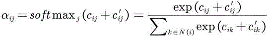
In some embodiments, the terminal can determine the weight of the impact of other nodes on the node based on equation (10) below. The terminal can determine the influence weight of the edge connected by the node on the node based on the following formula (11). Then, based on the formula (12), the two-part weight of the node is normalized through a softmax function, and then is processed through an additive attention mechanism. And finally, obtaining the fusion characteristics of the nodes based on the formula (13).

Wherein, representing the weight of the influence of node j on node i,
 a sigmoid function is represented as a function,
 the parameters of the model are represented by,
 the weight coefficient is represented by a weight coefficient,
 a feature vector representing the node i is shown,
 a feature vector representing the node j,
 representing vector stitching.

Wherein, representing nodesThe weight of the influence of the edge between j and node i on node i,
 a sigmoid function is represented as a function,
 the parameters of the model are represented by,
 the weight coefficient is represented by a weight coefficient,
 an edge feature vector representing an edge between node i and node j,
 representing model parameters.
Wherein, the normalized weights are represented by the weights of the samples,
 representing the weight of the influence of node j on node i,
 representing the weight of the influence of the edge between node j and node i on node i,
 a set of neighboring nodes representing node i includes an input temporally neighboring node and a spatially neighboring node.

Wherein, represents the fusion characteristics of the ith node,
 a sigmoid function is represented as a function,
 a set of neighboring nodes representing a node i,
 the normalized weights are represented by the weights of the samples,
 the weight coefficient is represented by a weight coefficient,
 representing the node characteristics of the ith node.
It should be noted that, in the embodiment of the present application, steps are numbered for convenience of description, the number does not limit the execution order of the steps, and in the embodiment of the present application, the execution order of the steps 305 and 306 is not limited.
307. And the terminal acquires the fusion characteristics of the edges in the graph network based on the node characteristics and the edge characteristics, wherein the fusion characteristics of the edges comprise the characteristics of the nodes connected with the edges in the graph network.
In the embodiment of the application, the fusion feature of the edge is determined by the terminal or is acquired by the terminal from the server. For any edge in the graph network, the fused feature of the edge can be obtained by fusing the feature of the edge and the feature of the node connected by the edge, so that the fused feature comprises the feature of the edge and the feature of the related node.
In some embodiments, the terminal determines the blending characteristics of the edges as an example. The terminal can obtain the intermediate fusion characteristics of the edges in the graph network based on the node characteristics, wherein the intermediate fusion characteristics of the edges comprise the characteristics of the nodes connected by the edges. The terminal can then determine a fused feature of the edge in the graph network based on the edge feature and the intermediate fused feature. The fused feature of the edge can be obtained by fusing the feature of the edge and the feature of the node connected by the edge, so that the fused feature includes both the feature of the edge and the feature of the related node.
In some embodiments, the terminal can process the edge-to-edge characteristics based on a layer of additive networks, as shown in equation (14) below. The terminal can then determine the intermediate fusion characteristics of the edges, as shown in equation (15). Finally, the terminal determines the edge blending feature based on equation (16).

Wherein, representing the characteristics of the edge between node i and node j undergoing additive network processing,
 a sigmoid function is represented as a function,
 the weight coefficient is represented by a weight coefficient,
 an edge feature representing an edge between node i and node j,
 representing model parameters.

Wherein, an intermediate blend feature representing an edge between node i and node j,
 a sigmoid function is represented by a function of,
 the weight coefficient is represented by a weight coefficient,
 represents the node characteristics of the ith node,
 representing the node characteristics of the jth node,
 representing the hadamard product.

Wherein, representing the fused features of the edges between node i and node j,
 a sigmoid function is represented by a function of,
 the weight coefficient is represented by a weight coefficient,
 representing the characteristics of the edge between node i and node j undergoing additive network processing,
 representing the intermediate fusion features of the edges between node i and node j,
 representing vector stitching.
308. And the terminal determines the first category information and the second category information based on the track characteristics, the fusion characteristics of the node and the fusion characteristics of the edge.
In the embodiment of the present application, the first category information is used to indicate a category to which a trajectory of an input operation belongs, the second category information is used to indicate a category to which an inter-trajectory relationship belongs, and the inter-trajectory relationship is used to indicate whether trajectories of two input operations belong to the same graph. The terminal can classify the track and determine the first type information based on the track characteristics, the fusion characteristics of the nodes and the edge fusion characteristics. The terminal can classify the relationship between the tracks based on the fusion characteristics of the nodes and the fusion characteristics of the edges, and determine second category information.
In some embodiments, the terminal can determine the class characteristics of the node in a manner similar to determining the fusion characteristics of the node, so as to classify the trajectory represented by the node based on the class characteristics of the node. First, the terminal can determine a trajectory fusion feature of the node based on the trajectory feature and the fusion feature of the node. Then, the terminal can obtain third weight information based on the track fusion characteristics of the node, wherein the third weight information is used for representing fusion weight between different nodes in the graph network. Then, the terminal can obtain fourth weight information based on the fusion characteristics of the edges, wherein the fourth weight information is used for representing the fusion weight corresponding to each edge in the graph network. Then, the terminal can acquire the class characteristics of the nodes in the graph network based on the third weight information and the fourth weight information, wherein the class characteristics of the nodes comprise the characteristics of the tracks of the input operation represented by the nodes, the fusion characteristics of other nodes in the graph network and the fusion characteristics of edges connected with the nodes. Finally, the terminal can determine the first category information based on the category characteristics of the node. By adding the track characteristics, the fusion characteristics of the nodes and the fusion characteristics of the edges into calculation, the three characteristics can be mutually influenced, so that the characteristics describing the track can be more carefully described, the recognition capability of a single figure is improved, and the accuracy in recognizing the flow chart with fewer figures is improved.
In some embodiments, the terminal can process the track features through the GRU, and then fuse the processed track features with the fusion features of the nodes to obtain the track fusion features of the nodes. See the following equations (17) and (18). The manner of determining the third weight information and the fourth weight information by the terminal is the same as the manner of determining the first weight information and the second weight information, and is not described herein again.

Wherein, represents the track characteristics after the processing of the GRU,
 representing the trajectory characteristics.
Wherein, a track fusion feature representing the ith node,
 a sigmoid function is represented by a function of,
 the weight coefficient is represented by a weight coefficient,
 the trajectory characteristic of the ith node is represented,
 the concatenation of the vectors is represented and,
 representing the fusion characteristics of the ith node.
In some embodiments, the terminal can determine the class characteristics of the edge in a manner similar to the determination of the fused characteristics of the edge, so as to classify the inter-track relationship represented by the edge based on the class characteristics of the edge. The method for determining the class characteristics of the edge by the terminal is the same as the method for determining the fusion characteristics of the edge, but the difference is that the input is replaced by the fusion characteristics of the node and the fusion characteristics of the edge, and the description is omitted here.
309. The terminal displays at least one graph corresponding to the plurality of input operations based on the first category information and the second category information.
In this embodiment, the terminal is capable of determining at least one graphic corresponding to the plurality of input operations based on the first category information and the second category information, and then displaying the at least one graphic in a standard editable format.
For example, referring to fig. 6, fig. 6 is a schematic diagram of a classification result provided according to an embodiment of the present application. As shown in fig. 6, the terminal determines the category to which the trajectory belongs and whether different trajectories belong to the same graph based on the first category information and the second category information. Six different trajectory categories are schematically shown in fig. 6, namely a text category 601, an arrow category 602, a data category 603, a decision category 604, a step category 605 and an end category 606. The relationship between the tracks includes two categories, where category 1 indicates that the tracks inside the detection box belong to the same shape, and category 0 indicates that the tracks inside the detection box and the tracks outside the detection box do not belong to the same shape.
It should be noted that the graph recognition scheme provided in the embodiment of the present application can be implemented based on a graph recognition model, where the graph recognition model includes a node layer, an edge layer, a sequence layer, and a combination layer. Referring to fig. 7, fig. 7 is a schematic structural diagram of a pattern recognition model according to an embodiment of the present application. As shown in fig. 7, the pattern recognition model includes a sequence layer 701 and a federation layer 702. And the sequence layer is used for processing the sequence characteristics, segmenting and pooling the sequence characteristics at the sampling point level to obtain the track characteristics at the track level, and processing the track characteristics by the GRU. The federation layer 702 includes a portion 7021 of node classifications, and a portion 7022 of edge classifications. Illustratively, the graph recognition model can also include a node layer and an edge layer, not shown in the figure.
It should be noted that, in order to make the framework of the pattern recognition scheme provided in the embodiment of the present application easier to understand, reference is made to fig. 8, where fig. 8 is a schematic diagram of a scheme framework provided in the embodiment of the present application. As shown in fig. 8, the method comprises the following steps: 801. a plurality of input operations on an input device are acquired. 802. And extracting sequence features. 803. Graph features, namely node features and edge features of the graph network, are extracted. 804. And processing the sequence features and the image features by a neural network module based on a fusion feature encoder, wherein the neural network module of the fusion feature encoder is used for processing the sequence features and the image features to obtain the category of the track and the category of the relationship between the tracks. 805. The category of the trajectory is obtained. 806. And acquiring the category of the relationship between the tracks. 807. And (5) restoring to obtain a standard graph.
According to the scheme provided by the embodiment of the application, the track sequence characteristic capable of accurately describing the input operation is introduced on the basis of the node characteristic and the edge characteristic, so that the graph corresponding to the input operation is determined on the basis of the sequence characteristic, the node characteristic and the edge characteristic, the recognition capability of a single graph can be improved, and the accuracy in recognizing the flow chart with few graphs is further improved.
Fig. 9 is a flowchart of a training method of a pattern recognition model according to an embodiment of the present application, and as shown in fig. 9, the embodiment of the present application is described as an example executed by a server. The method comprises the following steps.
901. The server inputs the tracks of the sample input operations into the pattern recognition model to obtain first prediction information and second prediction information, wherein the first prediction information is used for indicating the types of the track predictions of the sample input operations, the second prediction information is used for representing the types of the relationship predictions among the tracks, and the relationship among the tracks is used for representing whether the tracks of the two sample input operations belong to the same pattern.
In this embodiment, the manner in which the server determines the first prediction information and the second prediction information is similar to the manner in which the terminal determines the first category information and the second category information, and is not described herein again.
902. The server determines a first loss and a second loss based on the first prediction information, the second prediction information and the label graph corresponding to the trajectories of the plurality of sample input operations, wherein the first loss represents the loss of the category to which the predicted trajectory belongs, and the second loss represents the loss of the category to which the predicted inter-trajectory relationship belongs.
In the embodiment of the application, the server can perform two-stage training in a serial training mode, and the first stage is a learning stage of node features, edge features and sequence features of a graph network. The second stage is the output of the first stage, adopts a combined training mode, combines the advantage of fine and smooth description of the tracks by the sequence characteristics and the advantage of capturing the relationship between the tracks by the graph network, and improves the accuracy of node classification and the classification of the relationship between the nodes. Training the goal to minimize the loss of trajectory classification And loss of classification of relationships between traces
 。
。
Loss function Cross Entropy (CE), expressed as the error between the predicted and true categories of the trajectory. Because the number of samples among the trace classes in the training data is not uniform, the training of more trace class models is good, and the training of less trace class models is not good, so that the problem is alleviated by using weighted cross entropy in the design of the loss function, as shown in formula (19).

Wherein, representing a first loss, N represents the number of sample patterns contained in one batch in the training set,
 indicates the number of traces in the ith sample pattern in a batch,
 the category of the track is represented by,
 to represent
 The weight of (a) is determined,
 to represent
 The probability of (c).
It should be noted that, in the following description, from the median of class probabilities to the classes
 The ratio of the occurrence frequencies of (a) is obtained, so that the gradient loss per pass is smaller for the categories with the larger number of categories, and the gradient loss per pass is larger for the categories with the smaller number of categories.
Loss function And the cross entropy is also used for representing the error between the prediction category and the real category of the relationship between the tracks, wherein the relationship between the tracks refers to whether the two tracks belong to the same graph or not, 1 represents that the two tracks belong to the same graph, and 0 represents that the two tracks do not belong to the same graph. In the embodiment of the present application, weighted cross entropy is used to solve the problem of sample imbalance, as shown in formula (20)。

Wherein, representing the second loss, N represents the number of sample patterns contained in one batch in the training set,
 representing the set of edges in the ith sample graph in a batch,
 a category that represents the relationship between the tracks,
 to represent
 The weight of (a) is determined,
 to represent
 The probability of (c).
It should be noted that, in the following description, and classes in training set
 Is inversely proportional. When the relations among the tracks are classified, the number of the negative samples is larger than that of the positive samples, and the second loss can help the model to distinguish whether the tracks belong to the same shape, so that the model can accurately distinguish the connecting sides from the non-connecting sides even if the number of the non-connecting sides (namely, the negative samples) is larger than that of the connecting sides (namely, the positive samples).
903. The server trains the pattern recognition model based on the first loss and the second loss.
In an embodiment of the application, the server is capable of adjusting parameters of the pattern recognition model based on the first loss and the second loss. In some embodiments, the server can be trained using optimization algorithms such as random gradient descent, ADAM (Adaptive moment estimation) algorithms, and the like.
It should be noted that the graph recognition model includes a node layer, an edge layer, a sequence layer, and a joint learning layer. The joint learning layer is used for learning the category of the track and the category of the relationship between the tracks based on the output of the three layers. The scheme provided by the embodiment of the application can dynamically adjust the number of network layers in the graph recognition model when each feature learning layer independently learns, such as adjusting the number of network layers of a node layer, a side layer and a sequence layer in the graph recognition model; the number of network layers of the joint learning layer can be dynamically adjusted.
The scheme provided by the embodiment of the application avoids two defects caused by the fact that a traditional sequence difference characteristic model needs to use a clustering algorithm when classifying the relation between tracks, namely the model avoids the cascade error of the clustering algorithm depending on a track classification algorithm; the model also overcomes the defect that the clustering algorithm cannot distinguish the same class of different examples. The method and the device can finish the identification and restoration of the end-to-end flow chart. In addition, the pattern recognition model has less time (10 ms to 30 ms) in the inference stage, accurate recognition result and high recognition efficiency.
Fig. 10 is a block diagram of a pattern recognition apparatus according to an embodiment of the present application. The pattern recognition apparatus is used for executing the steps in the pattern recognition method described above, and referring to fig. 10, the apparatus includes: a first obtaining module 1001, a second obtaining module 1002, and a display module 1003.
A first obtaining module 1001, configured to obtain, based on a plurality of input operations on an input device, a sequence feature of the plurality of input operations, where the sequence feature is used to represent a difference between adjacent sampling points in a trajectory of the plurality of input operations.
The first obtaining module 1001 is further configured to obtain node features and edge features of a graph network representing the plurality of input operations, where nodes in the graph network are used to represent trajectories of the plurality of input operations, and edges in the graph network are used to represent a spatio-temporal relationship between the trajectories of the plurality of input operations, and the spatio-temporal relationship includes at least one of input temporal adjacency or spatial position adjacency.
A second obtaining module 1002, configured to obtain first category information and second category information based on the sequence feature, the node feature, and the edge feature, where the first category information is used to indicate a category to which a trajectory of an input operation belongs, the second category information is used to indicate a category to which an inter-trajectory relationship belongs, and the inter-trajectory relationship is used to indicate whether trajectories of two input operations belong to a same graph.
A display module 1003, configured to display at least one graph corresponding to the multiple input operations based on the first category information and the second category information.
In some embodiments, the first obtaining module 1001 is configured to sample the trajectories of the multiple input operations to obtain a sampling point sequence, where the sampling point sequence includes multiple sampling points; for any group of adjacent sampling points in the sampling point sequence, acquiring a transverse offset, a longitudinal offset and a continuity identifier between the adjacent sampling points, wherein the continuity identifier is used for indicating whether the adjacent sampling points belong to the same input operation; sequence features of the plurality of input operations are determined based on a plurality of sets of adjacent sample points in the sequence of sample points.
In some embodiments, referring to fig. 11, fig. 11 is a block diagram of another pattern recognition apparatus provided in an embodiment of the present application, the apparatus further including:
a graph network construction module 1004 for constructing nodes in the graph network based on the trajectory geometric attributes, trajectory positions, and spatiotemporal relationships between trajectories of the plurality of input operations; edges in the graph network are constructed between nodes corresponding to the trajectories based on the spatio-temporal relationship between the trajectories.
In some embodiments, the first obtaining module 1001 is configured to determine a node feature based on a geometric feature, a location feature, and a context feature of a trajectory of an input operation represented by the node in the graph network, where the context feature is used to represent a spatiotemporal relationship between the trajectories of the input operation; the edge features are determined based on spatiotemporal relationships between trajectories of input operations represented by edge-connected nodes in the graph network.
In some embodiments, referring to fig. 11, the second obtaining module 1002 includes:
a first acquisition unit 1101 configured to acquire trajectory characteristics of the plurality of input operations based on the sequence characteristics;
a second obtaining unit 1102, configured to obtain a fusion feature of a node in the graph network based on the node feature and the edge feature, where the fusion feature of the node includes features of other nodes in the graph network and features of an edge connected to the node;
a third obtaining unit 1103, configured to obtain, based on the node feature and the edge feature, a fused feature of an edge in the graph network, where the fused feature of the edge includes a feature of a node connected to the edge in the graph network;
a determining unit 1104, configured to determine the first category information and the second category information based on the track feature, the fusion feature of the node, and the fusion feature of the edge.
In some embodiments, the first obtaining unit 1101 is configured to segment the sequence feature to obtain a plurality of sequence feature segments, where the sequence feature segments include features of at least one group of adjacent sampling points; and pooling the sequence feature segments to obtain the track features of the input operations.
In some embodiments, the second obtaining unit 1102 is configured to obtain first weight information based on the node characteristics, where the first weight information is used to represent a fusion weight between two different nodes in the graph network; acquiring second weight information based on the edge characteristics, wherein the second weight information is used for representing fusion weights corresponding to all edges in the graph network; determining a fusion characteristic of a node in the graph network based on the first weight information and the second weight information.
In some embodiments, the third obtaining unit 1103 is configured to obtain, based on the node feature, an intermediate fused feature of an edge in the graph network, where the intermediate fused feature of the edge includes a feature of a node to which the edge is connected; based on the edge feature and the intermediate fused feature, a fused feature of the edge in the graph network is determined.
In some embodiments, the determining unit 1104 is configured to determine the first category information based on the trajectory feature, the fusion feature of the node, and the fusion feature of the edge; and determining the second category information based on the fusion characteristics of the node and the fusion characteristics of the edge.
In some embodiments, the determining unit 1104 is configured to determine a trajectory fusion feature of the node based on the trajectory feature and the fusion feature of the node; acquiring third weight information based on the track fusion characteristics of the nodes, wherein the third weight information is used for representing the fusion weight among different nodes in the graph network; acquiring fourth weight information based on the fusion characteristics of the edges, wherein the fourth weight information is used for representing the fusion weight corresponding to each edge in the graph network; acquiring the class characteristics of the nodes in the graph network based on the third weight information and the fourth weight information, wherein the class characteristics of the nodes comprise the characteristics of the track of the input operation represented by the nodes, the fusion characteristics of other nodes in the graph network and the fusion characteristics of edges connected with the nodes; the first category information is determined based on the category characteristics of the node.
According to the scheme provided by the embodiment of the application, the track sequence characteristic capable of accurately describing the input operation is introduced on the basis of the node characteristic and the edge characteristic, so that the graph corresponding to the input operation is determined on the basis of the sequence characteristic, the node characteristic and the edge characteristic, the recognition capability of a single graph can be improved, and the accuracy in recognizing the flow chart with few graphs is further improved.
It should be noted that: in the above-described embodiment, when performing the pattern recognition, the pattern recognition apparatus is exemplified by the division of the functional modules, and in practical applications, the function distribution may be completed by different functional modules according to needs, that is, the internal structure of the apparatus is divided into different functional modules, so as to complete all or part of the functions described above. In addition, the pattern recognition apparatus and the pattern recognition method provided by the above embodiments belong to the same concept, and specific implementation processes thereof are described in the method embodiments in detail and are not described herein again.
Fig. 12 is a block diagram of a training apparatus for a pattern recognition model according to an embodiment of the present application. The training apparatus of the pattern recognition model is used for executing the steps in the training method of the pattern recognition model, referring to fig. 12, and the apparatus includes: an input module 1201, a determination module 1202, and a training module 1203.
An input module 1201, configured to input trajectories of multiple sample input operations into a pattern recognition model, to obtain first prediction information and second prediction information, where the first prediction information is used to indicate categories of trajectory predictions of the multiple sample input operations, the second prediction information is used to indicate categories of inter-trajectory relationship predictions, and the inter-trajectory relationship is used to indicate whether trajectories of two sample input operations belong to the same pattern.
A determining module 1202, configured to determine a first loss and a second loss based on the first prediction information, the second prediction information, and a label graph corresponding to the trajectory of the plurality of sample input operations, where the first loss represents a loss of a category to which the predicted trajectory belongs, and the second loss represents a loss of a category to which the predicted inter-trajectory relationship belongs.
A training module 1203 is configured to train the pattern recognition model based on the first loss and the second loss.
It should be noted that: in the training apparatus for a pattern recognition model provided in the above embodiments, when training the pattern recognition model, only the division of the above functional modules is used as an example, and in practical applications, the above function distribution may be completed by different functional modules according to needs, that is, the internal structure of the apparatus is divided into different functional modules, so as to complete all or part of the above described functions. In addition, the training apparatus for the pattern recognition model and the training method embodiment for the pattern recognition model provided in the above embodiments belong to the same concept, and specific implementation processes thereof are described in detail in the method embodiments and are not described herein again.
In this embodiment of the present application, the device is a computer device, the computer device can be configured as a terminal or a server, when the computer device is configured as a terminal, the terminal can be used as an execution subject to implement the technical solution provided in the embodiment of the present application, when the computer device is configured as a server, the server can be used as an execution subject to implement the technical solution provided in the embodiment of the present application, and the technical solution provided in the present application can also be implemented through interaction between the terminal and the server, which is not limited in this embodiment of the present application.
When the computer device is configured as a terminal, fig. 13 is a block diagram of a terminal 1300 according to an embodiment of the present application. The terminal 1300 may be a portable mobile terminal such as: a smart phone, a tablet computer, an MP3 player (Moving Picture Experts Group Audio Layer III, motion video Experts compression standard Audio Layer 3), an MP4 player (Moving Picture Experts Group Audio Layer IV, motion video Experts compression standard Audio Layer 4), a notebook computer, or a desktop computer. Terminal 1300 may also be referred to by other names such as user equipment, portable terminal, laptop terminal, desktop terminal, etc.
In general, terminal 1300 includes: a processor 1301 and a memory 1302.
In some embodiments, terminal 1300 may further optionally include: a peripheral interface 1303 and at least one peripheral. Processor 1301, memory 1302, and peripheral interface 1303 may be connected by a bus or signal line. Each peripheral device may be connected to the peripheral device interface 1303 via a bus, signal line, or circuit board. Specifically, the peripheral device includes: at least one of radio frequency circuitry 1304, display screen 1305, camera assembly 1306, audio circuitry 1307, and power supply 1308.
The Radio Frequency circuit 1304 is used to receive and transmit RF (Radio Frequency) signals, also called electromagnetic signals. The radio frequency circuitry 1304 communicates with communication networks and other communication devices via electromagnetic signals. The radio frequency circuit 1304 converts an electrical signal into an electromagnetic signal to transmit, or converts a received electromagnetic signal into an electrical signal. In some embodiments, the radio frequency circuitry 1304 includes: an antenna system, an RF transceiver, one or more amplifiers, a tuner, an oscillator, a digital signal processor, a codec chipset, a subscriber identity module card, and so forth. The radio frequency circuitry 1304 may communicate with other terminals via at least one wireless communication protocol. The wireless communication protocols include, but are not limited to: the world wide web, metropolitan area networks, intranets, generations of mobile communication networks (2G, 3G, 4G, and 5G), Wireless local area networks, and/or WiFi (Wireless Fidelity) networks. In some embodiments, the radio frequency circuit 1304 may also include NFC (Near Field Communication) related circuits, which are not limited in this application.
The display screen 1305 is used to display a UI (User Interface). The UI may include graphics, text, icons, video, and any combination thereof. When the display screen 1305 is a touch display screen, the display screen 1305 also has the ability to capture touch signals on or over the surface of the display screen 1305. The touch signal may be input to the processor 1301 as a control signal for processing. At this point, the display 1305 may also be used to provide virtual buttons and/or a virtual keyboard, also referred to as soft buttons and/or a soft keyboard. In some embodiments, display 1305 may be one, disposed on the front panel of terminal 1300; in other embodiments, display 1305 may be at least two, either on different surfaces of terminal 1300 or in a folded design; in other embodiments, display 1305 may be a flexible display disposed on a curved surface or on a folded surface of terminal 1300. Even further, the display 1305 may be arranged in a non-rectangular irregular figure, i.e., a shaped screen. The Display 1305 may be made of LCD (Liquid Crystal Display), OLED (Organic Light-Emitting Diode), or the like.
The camera assembly 1306 is used to capture images or video. In some embodiments, camera assembly 1306 includes a front camera and a rear camera. Generally, a front camera is disposed at a front panel of the terminal, and a rear camera is disposed at a rear surface of the terminal. In some embodiments, the number of the rear cameras is at least two, and each rear camera is any one of a main camera, a depth-of-field camera, a wide-angle camera and a telephoto camera, so that the main camera and the depth-of-field camera are fused to realize a background blurring function, and the main camera and the wide-angle camera are fused to realize panoramic shooting and VR (Virtual Reality) shooting functions or other fusion shooting functions. In some embodiments, camera assembly 1306 may also include a flash. The flash lamp can be a monochrome temperature flash lamp or a bicolor temperature flash lamp. The double-color-temperature flash lamp is a combination of a warm-light flash lamp and a cold-light flash lamp, and can be used for light compensation at different color temperatures.
The audio circuit 1307 may include a microphone and a speaker. The microphone is used for collecting sound waves of a user and the environment, converting the sound waves into electric signals, and inputting the electric signals to the processor 1301 for processing, or inputting the electric signals to the radio frequency circuit 1304 for realizing voice communication. For stereo capture or noise reduction purposes, multiple microphones may be provided, each at a different location of terminal 1300. The microphone may also be an array microphone or an omni-directional pick-up microphone. The speaker is used to convert electrical signals from the processor 1301 or the radio frequency circuitry 1304 into sound waves. The loudspeaker can be a traditional film loudspeaker or a piezoelectric ceramic loudspeaker. When the speaker is a piezoelectric ceramic speaker, the speaker can be used for purposes such as converting an electric signal into a sound wave audible to a human being, or converting an electric signal into a sound wave inaudible to a human being to measure a distance. In some embodiments, audio circuitry 1307 may also include a headphone jack.
In some embodiments, terminal 1300 also includes one or more sensors 1309. The one or more sensors 1309 include, but are not limited to: acceleration sensor 1310, gyro sensor 1311, pressure sensor 1312, optical sensor 1313, and proximity sensor 1314.
The acceleration sensor 1310 may detect the magnitude of acceleration in three coordinate axes of the coordinate system established with the terminal 1300. For example, the acceleration sensor 1310 may be used to detect the components of the gravitational acceleration in three coordinate axes. The processor 1301 may control the display screen 1305 to display the user interface in a landscape view or a portrait view according to the gravitational acceleration signal collected by the acceleration sensor 1310. The acceleration sensor 1310 may also be used for acquisition of motion data of a game or a user.
The gyro sensor 1311 may detect a body direction and a rotation angle of the terminal 1300, and the gyro sensor 1311 may cooperate with the acceleration sensor 1310 to acquire a 3D motion of the user on the terminal 1300. The processor 1301 may implement the following functions according to the data collected by the gyro sensor 1311: motion sensing (such as changing the UI according to a user's tilting operation), image stabilization at the time of photographing, game control, and inertial navigation.
Pressure sensor 1312 may be disposed on a side bezel of terminal 1300 and/or underlying display 1305. When the pressure sensor 1312 is disposed on the side frame of the terminal 1300, a user holding signal of the terminal 1300 can be detected, and the processor 1301 performs left-right hand recognition or shortcut operation according to the holding signal collected by the pressure sensor 1312. When the pressure sensor 1312 is disposed at a lower layer of the display screen 1305, the processor 1301 controls the operability control on the UI interface according to the pressure operation of the user on the display screen 1305. The operability control comprises at least one of a button control, a scroll bar control, an icon control and a menu control.
The optical sensor 1313 is used to collect the ambient light intensity. In one embodiment, the processor 1301 may control the display brightness of the display screen 1305 according to the ambient light intensity collected by the optical sensor 1313. Specifically, when the ambient light intensity is high, the display brightness of the display screen 1305 is increased; when the ambient light intensity is low, the display brightness of the display screen 1305 is reduced. In another embodiment, the processor 1301 can also dynamically adjust the shooting parameters of the camera assembly 1306 according to the ambient light intensity collected by the optical sensor 1313.
Proximity sensor 1314, also known as a distance sensor, is typically disposed on the front panel of terminal 1300. Proximity sensor 1314 is used to capture the distance between the user and the front face of terminal 1300. In one embodiment, when the proximity sensor 1314 detects that the distance between the user and the front surface of the terminal 1300 gradually decreases, the processor 1301 controls the display 1305 to switch from the bright screen state to the dark screen state; the display 1305 is controlled by the processor 1301 to switch from the rest state to the bright state when the proximity sensor 1314 detects that the distance between the user and the front face of the terminal 1300 is gradually increasing.
Those skilled in the art will appreciate that the configuration shown in fig. 13 is not intended to be limiting with respect to terminal 1300 and may include more or fewer components than those shown, or some components may be combined, or a different arrangement of components may be employed.
When the computer device is configured as a server, fig. 14 is a schematic structural diagram of a server according to an embodiment of the present application, where the server 1400 may generate a relatively large difference due to different configurations or performances, and may include one or more processors (CPUs) 1401 and one or more memories 1402, where the memory 1402 stores at least one computer program, and the at least one computer program is loaded and executed by the processors 1401 to implement the training method for the graph recognition model provided by the above-described method embodiments. Of course, the server may also have components such as a wired or wireless network interface, a keyboard, and an input/output interface, so as to perform input/output, and the server may also include other components for implementing the functions of the device, which are not described herein again.
The embodiment of the present application further provides a computer-readable storage medium, where at least one piece of computer program is stored in the computer-readable storage medium, and the at least one piece of computer program is loaded and executed by a processor of a computer device to implement the operations performed by the computer device in the pattern recognition method of the foregoing embodiment. For example, the computer-readable storage medium may be a Read-Only Memory (ROM), a Random Access Memory (RAM), a Compact Disc Read-Only Memory (CD-ROM), a magnetic tape, a floppy disk, an optical data storage device, and the like.
The present application further provides another computer-readable storage medium, where at least one piece of computer program is stored in the computer-readable storage medium, and the at least one piece of computer program is loaded and executed by a processor of a computer device to implement the operations performed by the computer device in the training method for a pattern recognition model according to the foregoing embodiments. For example, the computer-readable storage medium may be a Read-Only Memory (ROM), a Random Access Memory (RAM), a Compact Disc Read-Only Memory (CD-ROM), a magnetic tape, a floppy disk, an optical data storage device, and the like.
Embodiments of the present application also provide a computer program product or a computer program comprising computer program code stored in a computer readable storage medium. The processor of the computer device reads the computer program code from the computer-readable storage medium, and the processor executes the computer program code, so that the computer device performs the pattern recognition method provided in the above-described various alternative implementations.
Embodiments of the present application also provide another computer program product or computer program comprising computer program code stored in a computer readable storage medium. The processor of the computer device reads the computer program code from the computer-readable storage medium, and executes the computer program code, so that the computer device executes the training method of the pattern recognition model provided in the above-mentioned various alternative implementations.
In some embodiments, the computer program according to the embodiments of the present application may be deployed to be executed on one computer device or on multiple computer devices located at one site, or may be executed on multiple computer devices distributed at multiple sites and interconnected by a communication network, and the multiple computer devices distributed at the multiple sites and interconnected by the communication network may constitute a block chain system.
It will be understood by those skilled in the art that all or part of the steps for implementing the above embodiments may be implemented by hardware, or may be implemented by a program instructing relevant hardware, where the program may be stored in a computer-readable storage medium, and the storage medium may be a read-only memory, a magnetic disk or an optical disk.
The above description is only exemplary of the present application and should not be taken as limiting, as any modification, equivalent replacement, or improvement made within the spirit and principle of the present application should be included in the protection scope of the present application.
Claims (15)
1. A method of pattern recognition, the method comprising:
acquiring sequence characteristics of a plurality of input operations on an input device, wherein the sequence characteristics are used for representing differences between adjacent sampling points in tracks of the input operations;
based on a graph network representing the plurality of input operations, obtaining node features and edge features of the graph network, wherein the nodes in the graph network are used for representing the tracks of the plurality of input operations, and the edges in the graph network are used for representing space-time relations among the tracks of the plurality of input operations, and the space-time relations comprise at least one of input time adjacency or space position adjacency;
acquiring first category information and second category information based on the sequence feature, the node feature and the edge feature, wherein the first category information is used for representing a category to which a track of an input operation belongs, the second category information is used for representing a category to which an inter-track relationship belongs, and the inter-track relationship is used for representing whether the tracks of two input operations belong to the same graph or not;
displaying at least one graph corresponding to the plurality of input operations based on the first category information and the second category information.
2. The method of claim 1, wherein obtaining the sequence feature of the plurality of input operations based on the plurality of input operations on the input device comprises:
sampling the tracks of the plurality of input operations to obtain a sampling point sequence, wherein the sampling point sequence comprises a plurality of sampling points;
for any group of adjacent sampling points in the sampling point sequence, acquiring a transverse offset, a longitudinal offset and a continuity identifier between the adjacent sampling points, wherein the continuity identifier is used for indicating whether the adjacent sampling points belong to the same input operation;
determining sequence characteristics of the plurality of input operations based on a plurality of sets of adjacent sample points in the sequence of sample points.
3. The method of claim 1, further comprising:
constructing nodes in the graph network based on the trajectory geometric attributes, trajectory positions and spatiotemporal relationships between trajectories of the plurality of input operations;
and constructing edges in the graph network among nodes corresponding to the tracks based on the space-time relation among the tracks.
4. The method of claim 3, wherein the obtaining node features and edge features of the graph network based on the graph network representing the plurality of input operations comprises:
determining the node characteristics based on the geometrical characteristics, the position characteristics and the context characteristics of the tracks of the input operation represented by the nodes in the graph network, wherein the context characteristics are used for representing the space-time relation among the tracks of the input operation;
the edge features are determined based on spatiotemporal relationships between trajectories of input operations represented by edge-connected nodes in the graph network.
5. The method according to claim 1, wherein the obtaining first category information and second category information based on the sequence feature, the node feature and the edge feature comprises:
acquiring track characteristics of the plurality of input operations based on the sequence characteristics;
acquiring fusion characteristics of nodes in the graph network based on the node characteristics and the edge characteristics, wherein the fusion characteristics of the nodes comprise characteristics of other nodes in the graph network and characteristics of edges connected with the nodes;
acquiring the fusion characteristics of the edges in the graph network based on the node characteristics and the edge characteristics, wherein the fusion characteristics of the edges comprise the characteristics of the nodes connected with the edges in the graph network;
determining the first category information and the second category information based on the trajectory features, the fusion features of the nodes, and the fusion features of the edges.
6. The method of claim 5, wherein obtaining trajectory features of the plurality of input operations based on the sequence features comprises:
segmenting the sequence features to obtain a plurality of sequence feature segments, wherein the sequence feature segments comprise features of at least one group of adjacent sampling points;
and pooling the sequence feature segments to obtain the track features of the input operations.
7. The method of claim 5, wherein obtaining the fused features of the nodes in the graph network based on the node features and the edge features comprises:
acquiring first weight information based on the node characteristics, wherein the first weight information is used for representing the fusion weight between two different nodes in the graph network;
acquiring second weight information based on the edge characteristics, wherein the second weight information is used for representing fusion weights corresponding to all edges in the graph network;
determining a fusion characteristic of a node in the graph network based on the first weight information and the second weight information.
8. The method according to claim 5, wherein the obtaining a fused feature of the edge in the graph network based on the node feature and the edge feature comprises:
acquiring intermediate fusion characteristics of edges in the graph network based on the node characteristics, wherein the intermediate fusion characteristics of the edges comprise characteristics of nodes connected by the edges;
determining a fused feature of an edge in the graph network based on the edge feature and the intermediate fused feature.
9. The method of claim 5, wherein determining the first category information and the second category information based on the trajectory feature, the fused feature of the node, and the fused feature of the edge comprises:
determining the first category information based on the track features, the fusion features of the nodes and the fusion features of the edges;
determining the second category information based on the fused features of the nodes and the fused features of the edges.
10. The method of claim 9, wherein determining the first category information based on the trajectory feature, the fused feature of the node, and the fused feature of the edge comprises:
determining track fusion characteristics of the nodes based on the track characteristics and the fusion characteristics of the nodes;
acquiring third weight information based on the track fusion characteristics of the nodes, wherein the third weight information is used for representing fusion weights among different nodes in the graph network;
acquiring fourth weight information based on the fusion characteristics of the edges, wherein the fourth weight information is used for representing the fusion weight corresponding to each edge in the graph network;
acquiring category characteristics of nodes in the graph network based on the third weight information and the fourth weight information, wherein the category characteristics of the nodes comprise characteristics of tracks of input operations represented by the nodes, fusion characteristics of other nodes in the graph network and fusion characteristics of edges connected with the nodes;
determining the first class information based on class characteristics of the node.
11. A method for training a pattern recognition model, the method comprising:
inputting tracks of a plurality of sample input operations into a pattern recognition model to obtain first prediction information and second prediction information, wherein the first prediction information is used for indicating the types of track predictions of the plurality of sample input operations, the second prediction information is used for representing the types of inter-track relation predictions, and the inter-track relation is used for representing whether the tracks of two sample input operations belong to the same pattern;
determining a first loss and a second loss based on the first prediction information, the second prediction information and label graphs corresponding to the trajectories of the plurality of sample input operations, wherein the first loss represents a loss of a category to which the predicted trajectory belongs, and the second loss represents a loss of a category to which the inter-trajectory relationship belongs;
training the pattern recognition model based on the first loss and the second loss.
12. A pattern recognition apparatus, characterized in that the apparatus comprises:
the device comprises a first acquisition module, a second acquisition module and a third acquisition module, wherein the first acquisition module is used for acquiring sequence characteristics of a plurality of input operations on an input device, and the sequence characteristics are used for representing differences between adjacent sampling points in tracks of the input operations;
the first obtaining module is further configured to obtain node features and edge features of a graph network representing the plurality of input operations, where nodes in the graph network are used to represent trajectories of the plurality of input operations, and edges in the graph network are used to represent spatiotemporal relationships between the trajectories of the plurality of input operations, where the spatiotemporal relationships include at least one of input temporal adjacency or spatial position adjacency;
a second obtaining module, configured to obtain first category information and second category information based on the sequence feature, the node feature, and the edge feature, where the first category information is used to indicate a category to which a trajectory of an input operation belongs, the second category information is used to indicate a category to which an inter-trajectory relationship belongs, and the inter-trajectory relationship is used to indicate whether trajectories of two input operations belong to a same graph;
and the display module is used for displaying at least one graph corresponding to the plurality of input operations based on the first category information and the second category information.
13. An apparatus for training a pattern recognition model, the apparatus comprising:
the input module is used for inputting the tracks of the multiple sample input operations into the pattern recognition model to obtain first prediction information and second prediction information, wherein the first prediction information is used for indicating the types of the track predictions of the multiple sample input operations, the second prediction information is used for representing the types of the inter-track relation predictions, and the inter-track relation is used for representing whether the tracks of the two sample input operations belong to the same pattern;
a determining module, configured to determine a first loss and a second loss based on the first prediction information, the second prediction information, and a label graph corresponding to a trajectory of the plurality of sample input operations, where the first loss represents a loss of a category to which a predicted trajectory belongs, and the second loss represents a loss of a category to which the predicted inter-trajectory relationship belongs;
a training module to train the pattern recognition model based on the first loss and the second loss.
14. A computer device, characterized in that the computer device comprises a processor and a memory for storing at least one piece of computer program, which is loaded by the processor and executes the pattern recognition method according to any one of claims 1 to 10, or which is loaded by the processor and executes the training method of the pattern recognition model according to claim 11.
15. A computer-readable storage medium for storing at least one computer program for executing the pattern recognition method according to any one of claims 1 to 10 or the training method of the pattern recognition model according to claim 11.
Priority Applications (1)
| Application Number | Priority Date | Filing Date | Title |
|---|---|---|---|
| CN202210298581.6A CN114397998B (en) | 2022-03-25 | 2022-03-25 | Pattern recognition method, pattern recognition model training method, device and equipment |
Applications Claiming Priority (1)
| Application Number | Priority Date | Filing Date | Title |
|---|---|---|---|
| CN202210298581.6A CN114397998B (en) | 2022-03-25 | 2022-03-25 | Pattern recognition method, pattern recognition model training method, device and equipment |
Publications (2)
| Publication Number | Publication Date |
|---|---|
| CN114397998A CN114397998A (en) | 2022-04-26 |
| CN114397998B true CN114397998B (en) | 2022-06-07 |
Family
ID=81234974
Family Applications (1)
| Application Number | Title | Priority Date | Filing Date |
|---|---|---|---|
| CN202210298581.6A Active CN114397998B (en) | 2022-03-25 | 2022-03-25 | Pattern recognition method, pattern recognition model training method, device and equipment |
Country Status (1)
| Country | Link |
|---|---|
| CN (1) | CN114397998B (en) |
Families Citing this family (1)
| Publication number | Priority date | Publication date | Assignee | Title |
|---|---|---|---|---|
| CN116311326A (en) * | 2023-03-09 | 2023-06-23 | 科大讯飞股份有限公司 | Hand-drawn flowchart recognition method, device, storage medium and electronic equipment |
Family Cites Families (7)
| Publication number | Priority date | Publication date | Assignee | Title |
|---|---|---|---|---|
| JP2001338294A (en) * | 2000-05-24 | 2001-12-07 | Monolith Co Ltd | Shape analyzer focusing on topology |
| US7174043B2 (en) * | 2003-02-25 | 2007-02-06 | Evernote Corp. | On-line handwriting recognizer |
| CN112017204A (en) * | 2020-07-08 | 2020-12-01 | 温州大学 | A tool state image classification method based on edge marker graph neural network |
| CN112711362B (en) * | 2020-12-24 | 2022-02-18 | 北京华宇信息技术有限公司 | Method and device for generating hand-drawn flow chart icon in standardized manner |
| US11228505B1 (en) * | 2021-01-29 | 2022-01-18 | Fujitsu Limited | Explanation of graph-based predictions using network motif analysis |
| CN113408417B (en) * | 2021-06-18 | 2024-11-29 | 北京搜狗科技发展有限公司 | Formula identification method and device for formula identification |
| CN113869308B (en) * | 2021-09-24 | 2025-06-17 | 珠海金山办公软件有限公司 | Graphics recognition method and device, storage medium and electronic device |
-
2022
- 2022-03-25 CN CN202210298581.6A patent/CN114397998B/en active Active
Also Published As
| Publication number | Publication date |
|---|---|
| CN114397998A (en) | 2022-04-26 |
Similar Documents
| Publication | Publication Date | Title |
|---|---|---|
| CN111914812B (en) | Image processing model training method, device, equipment and storage medium | |
| CN111325726B (en) | Model training methods, image processing methods, devices, equipment and storage media | |
| CN109299315B (en) | Multimedia resource classification method and device, computer equipment and storage medium | |
| CN111091132B (en) | Image recognition method and device based on artificial intelligence, computer equipment and medium | |
| CN110807361B (en) | Human body identification method, device, computer equipment and storage medium | |
| CN112749613B (en) | Video data processing method, device, computer equipment and storage medium | |
| CN113724189B (en) | Image processing methods, apparatus, devices and storage media | |
| CN114332530A (en) | Image classification method and device, computer equipment and storage medium | |
| CN110135336B (en) | Training method, device and storage medium for pedestrian generation model | |
| CN110490179B (en) | License plate recognition method and device and storage medium | |
| CN113570510A (en) | Image processing method, device, equipment and storage medium | |
| CN114511864B (en) | Text information extraction method, target model acquisition method, device and equipment | |
| CN112818979B (en) | Text recognition method, device, equipment and storage medium | |
| CN111597922A (en) | Cell image recognition method, system, device, equipment and medium | |
| CN117992898B (en) | Training method of anomaly detection model, object anomaly detection method and device | |
| CN114298268A (en) | Training method of image acquisition model, image detection method, device and equipment | |
| CN111753813B (en) | Image processing method, device, equipment and storage medium | |
| CN114397998B (en) | Pattern recognition method, pattern recognition model training method, device and equipment | |
| CN113723164A (en) | Method, device and equipment for acquiring edge difference information and storage medium | |
| CN115170767A (en) | Wire frame structure generation method and device, electronic equipment and readable storage medium | |
| CN114511082A (en) | Training method of feature extraction model, image processing method, device and equipment | |
| CN114842549B (en) | Training method, device, equipment, storage medium and product of action recognition model | |
| CN114627470B (en) | Image processing method, image processing device, computer equipment and storage medium | |
| CN115937738A (en) | Training method, device, equipment and storage medium of video tagging model | |
| CN111259252B (en) | User identification recognition method and device, computer equipment and storage medium |
Legal Events
| Date | Code | Title | Description |
|---|---|---|---|
| PB01 | Publication | ||
| PB01 | Publication | ||
| SE01 | Entry into force of request for substantive examination | ||
| SE01 | Entry into force of request for substantive examination | ||
| GR01 | Patent grant | ||
| GR01 | Patent grant |