Detailed Description
The invention is further illustrated by the following examples, which are not intended to limit the scope of the invention.
In the following embodiments and examples, the maximum battery capacity of a unit cell of a lithium battery is 180 Ah.
The invention provides a dynamic management and control method of a lithium battery energy storage system, wherein the lithium battery energy storage system comprises a battery pack and a Battery Management System (BMS) which are obtained by connecting a plurality of single battery cells in series and/or in parallel, and referring to fig. 1, the dynamic management and control method of the lithium battery energy storage system in an embodiment of the invention comprises the following steps:
s1, reading the current operation data flow of the battery cell of each single battery cell by the BMS, wherein the current operation data flow at least comprises internal resistance and capacity;
s2, the EMS diagnoses whether the battery pack has a fault or has potential safety hazard according to the current operation data stream, if the battery pack has the fault or has the potential safety hazard, the step S3 is executed;
s3, sending fault information to a user, generating control parameters according to the diagnosis result, sending the current operation data stream to the intelligent gateway, and sending the control parameters to the BMS so that the BMS controls the charging and discharging of the battery pack according to the control parameters;
s4, the intelligent gateway sends the current operation data stream to the battery diagnosis cloud platform;
and S5, the battery diagnosis cloud platform extracts characteristic values of each battery cell from the current operation data flow, compares the consistency of each characteristic value with historical data to judge whether the battery pack is in fault or has potential safety hazard, and locates the abnormal battery cell according to one characteristic value when the consistency of the one characteristic value exceeds a first reliability threshold or a first safety threshold or when the one characteristic value exceeds a second reliability threshold or a second safety threshold.
In a specific implementation process, the dynamic management and control system of the lithium battery energy storage system may include an EMS, a battery energy storage system, an intelligent gateway, and a battery diagnosis cloud platform in bidirectional communication with the intelligent gateway, and the dynamic management and control method may be correspondingly implemented by using the dynamic management and control system.
The first reliability threshold and the second reliability threshold define the boundary of a normal state and a sub-health state of the lithium battery energy storage system, the first safety threshold and the second safety threshold define the boundary of the lithium battery energy storage system in the sub-health state and in a state that potential safety hazards exist and need to be decommissioned, and the charge and discharge control parameters of the normal state, the sub-health state and the decommissioning state meet the following relations: i isIs normal≥ISub-health≥IDecommissioning,Vmax is normal≥Vmax sub-health≥Vmax retirement,Vmin is normal≤VSub-health of min≤Vmin retirement(ii) a Wherein IIs normal、ISub-healthAnd IDecommissioningCharge or discharge currents, V, representing normal, sub-health and retirement states, respectivelymax is normal、Vmax sub-healthAnd Vmax retirementCharge voltage thresholds, V, representing normal, sub-health and retirement states, respectivelymin is normal、VSub-health of minAnd Vmin retirementRepresenting the discharge voltage thresholds for the normal, sub-health and retirement states, respectively.
For example, the battery energy storage system may be an energy storage BMS formed by connecting n individual cells (electric cores) in series to form a module, then connecting m in series to form a cluster, connecting j clusters in parallel to form the whole energy storage system, and controlling j battery cluster BMS by one BMS, wherein the energy storage BMS is formed by a middle-layer controller of the BMS and m × j BMS slave controllers; the layer manager in the cluster BMS determines whether the cluster participates in the charging and discharging process and the charging and discharging current of the whole battery pack through the switch of the clusterAnd simultaneously sends out instructions to ensure that the voltage of each battery cell controlled by the BMS slave of the module under the control is in a fixed range in the charging and discharging process, namely Vmin<Vi< V max1,2,. n, wherein Vmin>Vmini、Vmax<Vmaxi,VminiAnd VmaxiThe discharge voltage threshold and the charge voltage threshold of the lithium battery in the initial normal state are respectively. The total positive and total negative of the battery pack are connected to the total positive and total negative of the energy converter.
Referring to fig. 2, the disassembly-free detection and diagnosis of the battery energy storage full life cycle CAN be realized by using the management and control method, in the charging and discharging processes of the whole battery pack energy storage system, the BMS master control and the energy converter perform bidirectional communication by agreement of the industry, namely, CAN communication or Modbus communication exchanges information, and in the charging process, the BMS master control diagnoses whether the battery pack has a fault or has a potential safety hazard by operating the current data stream acquired from the BMS by a real-time fault diagnosis method, and transmits the data stream to the battery diagnosis cloud platform through the intelligent communication gateway. The battery diagnosis cloud platform extracts battery characteristic values such as internal resistance and capacity from the data flow of the battery cell layer, and diagnoses the potential safety hazard of the battery pack and positions a fault battery cell by comparing the consistency of the characteristic values with historical data of the characteristic values. When the current operation value or consistency of the characteristic value of the battery exceeds the reliability and safety threshold value so as to send an alarm instruction, the BMS master control or the cloud platform automatically sends an order to a maintenance or operation personnel through an EMS (energy management system), and the BMS master control or the cloud platform is required to carry out further offline operation detection and maintenance according to preset operation rules and intelligent maintenance regulations; simultaneously, the BMS master control sends out charge and discharge current I of a battery cluster which dynamically changes and finds out a fault battery cell downwards and controls a threshold value V through charge and discharge voltage of the fault battery cellminAnd VmaxThe potential safety hazard is effectively controlled before online down-stream inspection, so that the effects of intelligently and dynamically adjusting BMS control parameters to control the potential safety hazard without manual participation and recovering to the control threshold value in a normal state after intelligent maintenance are achieved. For example, when a certain characteristic value or the consistency of a certain characteristic value exceeds a safety threshold, a serious fault is considered to exist, and the requirement is metAnd (4) performing switching management on a battery cluster where the fault battery cell is located. If only general faults occur, the sub-health management mode is considered, and operation and maintenance personnel are notified to process the sub-health management mode.
Specifically, the internal resistance is determined by the sum of the real-time voltage data of the single battery cells and the R ═ u ═1-u2) I, calculating direct current internal resistance, and diagnosing whether general faults and serious faults exist according to whether the direct current internal resistance is greater than a second reliability threshold value of the internal resistance and a second safety threshold value of the internal resistance, wherein u1Is a voltage value at the time of initial charge or discharge, u2The voltage value is the voltage value when the battery is placed still before charging. And the second reliability threshold value of the internal resistance and the second safety threshold value of the internal resistance are determined according to the change rule of the characteristic values of the batteries of the same batch of lithium batteries in the aging process. Preferably, the second reliability threshold value and the second safety threshold value of the internal resistance are respectively 1.5-2 times and 4.5-5 times of the initial internal resistance of the battery cell.
Specifically, the EMS is used to diagnose whether the battery pack is malfunctioning or has a safety hazard based on whether the difference between the maximum and minimum voltages of the battery pack is greater than a difference threshold, where the difference threshold is charging current internal resistance threshold + VSet valueIn which V isSet valueThe parameter is a parameter reflecting the consistency of the battery pack, and represents the battery pressure difference of the battery pack when the self-discharge and SOC of the battery pack are inconsistent during the normal operation of the lithium battery energy storage system.
In addition, the EMS is used for diagnosing whether the battery pack is in failure or has a potential safety hazard according to whether the voltage of each battery cell in the charging process of the battery pack is lower than a third threshold value along with the increase of the SOC.
The BMS is configured to extract internal resistance and capacity from the data stream during charging by: obtaining the differential change dQ/dV of the electric quantity Q ═ Idt along with the voltage from the data flow of the electric core i, and obtaining the V when the dQ/dV reaches the maximum value
imaxIs an equivalent voltage platform of the i-cell and the internal resistance R of the cell
i=(V
imax-OCV
i) I, where I is the charging current, OCV
iIs the open circuit voltage; capacity of it
Wherein Δ Q
iIs dQ-Capacity difference between the first and maximum peaks of the dV curve, Δ SOC
iIs the difference in SOC between the two peaks, Q
iIs the maximum capacity at full charge, wherein data satisfying the condition that Δ V is greater than or equal to X is recorded during the charging process of the battery pack; and according to
Determining a characteristic value, and recording the charging capacity of a point corresponding to the characteristic value; wherein: q is the charge capacity of the battery, dQ is the differential of the capacity, Δ Q
kIs the difference in capacity between adjacent samples, V is the voltage of the cell, dV is the differential of the voltage, Δ V
kFor the difference in voltage between adjacent samples, Δ Q for each sample point k
k=Q
k-Q
k-1,ΔV
k=V
k-V
k-1(ii) a Wherein the value range of X is more than or equal to 1mV and less than or equal to 10 mV.
A second reliability threshold and a second safety threshold for the internal resistance, capacity, and OCV are obtained by performing HPPC condition correction. The EMS is used for calculating the internal resistance of the i electric core corresponding to each SOC value based on the voltage change value delta Vi of the front end and the back end of the pulse, so as to obtain an R-SOC curve and an OCV-SOC curve of the electric core i, and calculating the effective capacity C of the whole battery pack determined by the electric core which reaches the charging cut-off voltage firstly according to the sum of the charging time obtained by deducting the rest time and the pulse time in the whole process. Wherein the second reliability threshold and the second safety threshold of the rectification are any value of [0.8,1.2] multiplied by the value before the rectification.
The EMS is used for standing the first time period after the HPPC test correction is completed, recording OCV (open Circuit) at two ends of each battery cell in the second time period and the second time period, and calculating delta OCV (open Circuit voltage)A second period of time-OCVA first period of timeAnd comparing the voltage difference with a second reliability threshold value and a second safety threshold value of the voltage difference provided by the manufacturer to judge whether the self-discharge rate has problems, wherein the second time period is shorter than the first time period.
In addition, the EMS has a bidirectional communication function with encryption and is used to issue commands according to a preset rule for electric energy scheduling through energy conversion devices including an ac-dc converter, an inverter, a bidirectional inverter, or a dc-dc converter.
The BMS is also used for storing maximum transient discharge current and continuous charge and discharge current, charge and discharge voltage threshold values of the single battery cell and charge and discharge voltage threshold values of the battery pack, wherein the initial values and the current control values of the parameters meet the following requirements: the BMS is used for periodically acquiring control parameters from the intelligent gateway and updating the control parameters. The BMS is used for determining the current charging or discharging current, the current charging or discharging time interval and the current voltage threshold value of each battery cluster which belongs to the BMS according to the requirements of the maximum power or/and the total energy for charging or discharging of the lithium battery energy storage system and the current SOC of each single battery cell of the lithium battery energy storage system, and is used for balancing when the consistency of the battery voltage exceeds the preset threshold value according to a preset rule, wherein the battery clusters are formed by connecting battery packs in series and in parallel.
The intelligent gateway is integrated in an EMS or a BMS. The intelligent gateway is used for storing fault codes, fault information and charging and discharging control parameters, wherein the fault information comprises serious fault information and general fault information; wherein the serious fault information comprises a micro short circuit precursor, thermal runaway, insulation abnormity, overheating, communication abnormity, and a battery characteristic value or a consistency parameter thereof is equal to or exceeds a safety threshold value; the general fault information comprises battery under-voltage, battery over-voltage, low SOC, high SOC, balance fault, and battery characteristic value or consistency parameter exceeding reliability threshold but lower than safety threshold.
The battery diagnosis cloud platform performs data analysis on historical data of each single battery cell or battery cell voltage, determines battery characteristic values such as direct current internal resistance, capacity and SOC of each battery cell and change trend of consistency of the battery characteristic values along with time, establishes a model describing change of the battery characteristic values and consistency of the battery characteristic values along with time, and predicts that current values of the battery characteristic values will change along with timeThe BMS is used for automatically adjusting the charging and discharging control parameters according to the following modes to ensure that the system charging and discharging control parameters can ensure the safety and the system service life is not influenced before the operation maintenance is carried out according to the positions of the battery characteristic value and the consistency relative to the second reliability threshold value, the second safety threshold value, the first reliability threshold value and the first safety threshold value: when the battery characteristic value exceeds a second reliability threshold value but is smaller than a second safety threshold value and the consistency of the battery characteristic value exceeds a first reliability threshold value but is smaller than a first safety threshold value and corresponds to a sub-health state, the BMS sets the maximum transient and continuous charging and discharging current I at the cell levelSub-health=α*IIs normalWherein alpha is 0.5-0.9, and charging voltage control parameter Vmax sub-health=kcVmax is normalWherein k iscThe value of SOC is between 80% and 95%, and the discharge voltage controls a parameter VSub-health of min=kdVmin is normalWherein k isdThe value is taken to ensure that the SOC is between 5 and 20 percent; when the characteristic value of the battery is larger than the second safety threshold and the consistency of the characteristic value of the battery is larger than the first safety threshold and corresponds to the retired state, the BMS sets the maximum transient state and the continuous charging and discharging current I on the electrical core layerDecommissioning=α’*IIs normalWhere α' < α, a charge voltage control parameter Vmax retirement=kc’Vmax is normalWherein k iscThe value is such that SOC is between 65% and 80%, kc’<kc< 1, discharge voltage control parameter VSub-health of min=kd’Vmin is normalWherein k isdThe value is such that SOC is between 20% and 35%, kd’>kd>1; the dynamic management and control system automatically adjusts to a sub-health state when serious fault information disappears but general fault information still exists after operation maintenance is implemented, and the system recovers to a normal operation state when the general fault information also disappears.
Specifically, the current control parameter alpha in the sub-health state is taken as (R)i/Rmax)1/2And Ri/RmaxTherein, whereinRiAnd RmaxRespectively representing the initial cell internal resistance and the current maximum cell internal resistance.
The technical solution of the present invention is further illustrated by several application examples.
Example 1:
taking a lithium iron phosphate battery utilized in small and medium-sized echelons as an example of building energy storage (fig. 3), the dynamic management and control device is composed of a battery energy storage system master control EMS, a bidirectional inverter PCS, a battery energy storage system, an intelligent gateway iRouter and a battery diagnosis cloud platform in bidirectional communication with the intelligent gateway iRouter. The battery energy storage system comprises n (10) battery clusters, each cluster is composed of 6 modules, each module is composed of 24 initial capacity 60Ah battery cores, an energy storage battery pack formed by connecting national grid retired batteries of 3.2V in series, and a three-level BMS for managing the energy storage battery pack.
The EMS sends a charging and discharging instruction to the PCS to realize charging or discharging operation, the three-level BMS carries out data acquisition on the battery pack in the charging and discharging process, the acquired data comprises total (battery pack) charging and discharging current, total voltage of the battery pack, current flowing through each battery cluster and charging and discharging voltage of a single layer (namely a single battery cell in each battery cluster), meanwhile, the current is compared with charging and discharging key control parameters stored in a memory thereof according to the currently acquired voltage, the charging and discharging control parameters comprise total maximum transient state and continuous charging and discharging current passing through each battery cluster, threshold values of the single layer and the total charging and discharging voltage and the like. If any value of the current sum of the charging and discharging current passing through each cluster and the total or single voltage of the battery pack exceeds the threshold value of the key control parameter of the BMS master control, the BMS master control gives an alarm, and the current is cut off to carry out safety protection on the battery pack. The BMS master control determines the current charging or discharging current, the charging or discharging time interval and the threshold value of each battery cluster subordinate to the battery cluster according to the requirements of the system master control EMS on the maximum power or/and the total energy of the battery pack charging or discharging and the SOC of each single battery cell of the battery cluster obtained from the BMS middle-layer controller (the battery cluster management unit in the figure 3) of each cluster, and performs equalization when the consistency of the battery and the voltage exceeds the preset threshold value according to the preset rule through the BMS slave control in the cluster.
The diagnosis cloud platform acquires historical data of each single battery cell from a three-level BMS master control (BMS master control) through an intelligent gateway iRouter, performs data analysis, determines characteristic values of direct current internal resistance, capacity, self-discharge rate and the like of each single battery cell and the change trend of the characteristic values along with time, establishes a model describing the change of the characteristic values along with time, and then predicts the future development trend of the characteristic values; according to the research on the aging process of the lithium iron phosphate battery, the reliability threshold value of the internal resistance of the lithium iron phosphate battery is 6m omega, and the safety threshold value of the internal resistance of the lithium iron phosphate battery is 13m omega; simultaneously according to real-time data of the monomers and corresponding formulas

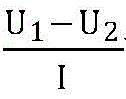
Calculating the internal DC resistance, wherein U
1Is the voltage value at the beginning of charging, U
2Is voltage value (U) of static state before charging
1,U
2Is data acquired from the BMS master control), the current internal dc resistance of the cell is compared with the internal dc resistance value on its specification to diagnose it. Fig. 4 shows dc internal resistance data of the 2 nd retired lithium iron phosphate battery box in the No. 1 battery cluster. Referring to fig. 4, only 4, 5, 8, 10, 21, 22, 23 of the 24 unit cells belong to "normal",
numbers 2, 3, 7, 9, 11, 13, 17, 18, 19, 20 and 24 are in "sub-health" with reliability risk, while
numbers 1, 6, 14, 15, and 16 unit cells have internal resistances exceeding a safety threshold of 13m Ω, and are in a state where "safety risk" of serious failure requires "retirement" again (only the unit cells in serious failure are indicated in fig. 5). Assuming that no
serious fault cells 1, 6, 14, 15 and 16 exist and only general alarm of sub-health state exists, parameters such as charge and discharge maximum current and the like can be dynamically corrected to be current values between 0.5 and 0.9 of the original values, so that intelligent dynamic regulation of BMS control parameters is achieved, and meanwhile, a system master control EMS (energy management system) automatically dispatches orders to maintenance or operation personnel, so that sub-health monomers can carry out further offline operation detection and maintenance as soon as possible according to preset operation and inspection rules and intelligent maintenance rules, and further offline operation detection and maintenance are prevented in the charge and discharge process of the batteryThe situation of over-high temperature rise and the like occurs. Due to the existence of a seriously-faulty battery cell (namely, the battery cell which has a potential safety hazard and needs to be retired again), the BCMU of the No. 1 battery cluster receives an instruction to disconnect the breaker for switching on and off management, and simultaneously informs operation and maintenance personnel to carry out operation and maintenance as fast as possible.
When the charging data is processed, once the situation that the voltages of the number 1, 3, 14, 15 and 16 monomer cells do not rise but fall and the cumulative value of the fall exceeds 30mV during the charging process is detected (shown in fig. 5), the number 1 cell is judged to have a "micro short circuit precursor" and belongs to a state of "having a potential safety hazard" and needing to be retired again ", and then the number 1 cell cluster management unit BCMU1 is notified to perform retirement management on the number 1 cell cluster. The processing data may be in a BMS, smart gateway, or diagnostic cloud platform.
Example 2:
taking the container energy storage power station as an example, referring to fig. 6-14, the dynamic management and control device at this time is composed of a bidirectional inverter PCS, a battery energy storage system master control EMS, a battery energy storage system, an intelligent gateway iruterer function and BMS master control integrated together, and an iBMS master control and a battery diagnosis cloud platform in bidirectional communication therewith. The battery energy storage system is composed of n battery clusters, an energy storage battery pack formed by connecting 240 single battery cores 180Ah and 3.2V lithium iron phosphate batteries in series in each cluster, and a three-level BMS for managing the energy storage battery pack. The battery reference curve data used was SOC-OCV curve data, and the data interval was Δ SOC of 2%. The capacity value corresponding to each OCV point of each cluster is represented by the formula: q is calculated as SOC 180 Ah.
The method comprises the steps that an EMS sends a charging and discharging instruction to a PCS to realize charging or discharging operation, in the charging and discharging process, the BMS master controller obtains voltage data on a cell layer from a BMS middle-layer controller of each battery cluster and transmits the voltage data and current of the cluster to a cloud platform, the cloud platform adopts a five-point three-time smoothing filtering method (2 data before and after the position to be smoothed is selected and 5 data are obtained in total, a 3-order polynomial is adopted for fitting, and the value after smoothing filtering is obtained) to obtain a capacity increment curve of SOC-OCV relation data, the SOC-OCV relation graph is shown in figure 7, and the obtained capacity increment curve is dQ/dV (the change of electric quantity relative to voltage) in figure 8Degree), fig. 8 is a dotted line with SOC as abscissa, left ordinate is battery open-circuit voltage OCV, right ordinate is dQ/dV, 1 st eigenvalue (maximum of electric quantity with respect to voltage change (dQ/dV) in a conventionally accepted method for dQ/dV) position is a point position a in fig. 8, corresponding to SOC of 55.6%, capacity Q is1The 2 nd eigenvalue position in the graph is the B point position in fig. 8, corresponding to an SOC of 84.9%, at 100.08Ah, and the capacity Q is2=152.82Ah。
Calculating a relation coefficient between the capacity among the characteristic values of the battery and the real capacity of the battery:
g=ΔQ/Capinitial=|Q2-Q1|/Capinitial=(152.82-100.08)/180=0.293
fig. 9 shows a capacity increment curve of the No. 1 unit cell in the battery pack, where fig. 9 is a graph in which SOC is plotted on the abscissa, the left ordinate is battery voltage, the right ordinate is dQ/dV, the 1 st characteristic value position in the graph is the C point position in fig. 9, and the corresponding charge capacity value is Q'1167.66Ah, the 2 nd eigenvalue position in the figure is the D point position in figure 9, and the corresponding charge capacity value is Q'21119.2 Ah; calculating the total capacity of the No. 1 single battery cell of the battery cluster:
Cap1=ΔQ1/g=|Q‘21-Q‘11|/g=(119.2-67.06)/0.293=177.9Ah
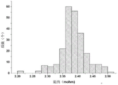
the same calculation method calculates the total capacity of the No. 2 single battery cell to the total capacity of the No. 240 single battery cell in the battery pack, and draws the total capacity of all the single battery cells into a histogram, where fig. 10 is a histogram of the capacities of all the single battery cells in the battery cluster. And comparing the capacity value calculated by the method of the present invention with the rated capacity value of the battery, the capacity error rate is shown in fig. 11, which shows that the maximum capacity error is 3.86%. Correspondingly, V of the capacity increment curveimaxAt the position of C point in FIG. 9, the corresponding voltage and current are Vimax3.358V, and 63A. Calculating the resistance value of the No. 1 single battery cell of the battery pack: (from the SOC-OCV relationship, the value of OCV corresponding to SOC, i.e., OCV, can be found1))
R1=(V1max-OCV1)/I=2.47mΩ
The same calculation method calculates the resistance values of the No. 2 cell to the No. 240 cell in the battery pack, and respectively plots the resistance values of all the cell into a histogram, as shown in fig. 12, which is a distribution diagram of the resistance values of all the cells in the battery cluster. Therefore, the resistance value of each single battery cell can be quickly obtained without additionally testing the battery parameters in the normal charging process of the battery cluster.
Wherein, as shown in fig. 13, the calculation formula of the battery pack capacity is C
packnow=Q
dis,min+Q
cha.minWherein Q is
dis,minRepresenting the minimum dischargeable charge, Q, of the battery pack at that time
cha.minRepresenting the minimum amount of charge that the battery pack can be charged with at this time. And Q
dis,minAnd Q
cha.minCan be obtained by the following method: pulse experiments as described by FIG. 14, using equation
And
and obtaining corresponding OCV value by U ═ OCV + RI, obtaining the current real SOC value of each monomer by using the SOC-OCV curve relation, and combining the capacity of each monomer obtained by the calculation to calculate the Q of each monomer
disAnd Q
cha. Therefore, the current new SOH value can be corrected to C
packnow/C
iniCorrection amount ═ Δ C/C
ini,ΔC=C
packnow-C
packbefore. Further, the SOC can be corrected, and the ampere-hour integral formula of the SOC is calculated as
Therefore, the current SOC is corrected to
Correction amount Δ SOC ═ 1/C
packbefore-1/C
packnow)
The method comprises the following steps of obtaining battery characteristic values and consistency reliability and safety threshold values of the battery characteristic values and consistency of the same batch of lithium batteries in the aging process according to the change trend of the battery characteristic values and consistency of the same batch of lithium batteries with the same type. And establishing a model describing the change of the characteristic values along with time so as to predict the future development trend of the characteristic values and establishing a dynamic reliability threshold value of the characteristic values with abnormity.
Example 3:
take the intelligent energy storage backup system for dc load as an example (fig. 15, for the communication base station, the dc voltage is-48V). The dynamic management and control device comprises an AC/DC rectifier, an energy management unit EMS (energy management system), an intelligent Internet of things gateway iRouter, a cloud platform diagnosis and analysis system and a plurality of sets of energy storage and standby power systems, wherein each set of energy storage and standby power system consists of a bidirectional DC/DC and a battery cluster, and each lithium battery cluster is formed by taking a BMS (battery management system) main control BCU (battery management unit) as a management unit and taking a BMS (battery management unit) as a slave BMU with the functions of electric core acquisition and the like under the BMU to manage and control the battery module. The energy management unit is equivalent to the effect of integrating EMS and battery management master control together, the energy management unit sends out instructions through bidirectional DC/DC to control charging and discharging of each battery cluster, determines that the sum of enough standby power capacity of each set of energy storage standby power system can meet the requirement of the standby power supply according to the requirement of the standby power supply, and other energy storage standby power systems can be used for 'peak clipping and valley filling' to generate economic benefit, and meanwhile, each set of energy storage standby power system can discharge to cut-off voltage to verify the capacity of the standby power supply; the intelligent internet of things gateway iRouter acquires voltage and temperature information of a battery cell layer through a main control BCU in the charging and discharging process of each lithium battery cluster, diagnoses the battery cell layer at the edge, and uploads the information to a diagnosis cloud platform at the same time. As in examples 1 and 2, the intelligent internet of things gateway iRouter and the diagnosis cloud platform perform disassembly-free detection diagnosis on each lithium battery cluster at the cell level according to fig. 2, dynamically change control parameters on the one hand to improve safety based on the diagnosis result of the state of each cell, and inform operation and maintenance personnel to timely recover normal operation even if operation and maintenance are performed according to preset operation and maintenance rules, so that the effect of intelligent operation and maintenance is achieved.
Example 4
Take an intelligent energy storage and backup system for ac loads as an example (fig. 16). The dynamic control device comprises an AC/DC rectifier, an energy storage and standby power system, a DC/AC, a system energy unit EMS, an intelligent Internet of things gateway iRouter and a cloud platform diagnosis and analysis structure from a power grid to a bypass switch (not shown) of an alternating current load. The energy storage is equipped with electric system and is responsible for the management and control to the battery module by a BMS main control BCU as the administrative unit and through the subordinate accuse BMU that has functions such as electric core collection under it. The energy management unit determines that the lithium battery energy storage system is bypassed, charged or discharged by sending instructions to the bypass switch, the AC/DC and the DC/AC, determines that the reserved standby power capacity of the energy storage standby power system can meet the requirement of the standby power supply according to the requirement of the standby power supply, and other energy storage standby power systems can generate economic benefit by peak clipping and valley filling, and meanwhile, regularly discharges the energy storage standby power system to cut-off voltage to verify the capacity of the standby power supply in the scene of excellent mains supply; in the charging and discharging process, the intelligent internet of things gateway iRouter acquires voltage and temperature information of the battery cell layer through the main control BCU, diagnoses the intelligent internet of things gateway iRouter and uploads the information to the diagnosis cloud platform for analysis. As in examples 1 and 2, the intelligent internet of things gateway iRouter and the diagnosis cloud platform perform disassembly-free detection diagnosis on each lithium battery cluster at the cell level according to fig. 2, dynamically change control parameters on the one hand to improve safety based on the diagnosis result of the state of each cell, and inform operation and maintenance personnel to timely recover normal operation even if operation and maintenance are performed according to preset operation and maintenance rules, so that the effect of intelligent operation and maintenance is achieved.
Example 5
As can be seen from the above examples and embodiments, the single battery cells in the lithium battery are connected in series, and then the charging current/discharging current of each single battery cell, the charging current/discharging current of each battery cluster of the lithium battery, and the charging current/discharging current of the battery pack of the lithium battery are all the same.
This embodiment provides a lithium cell energy storage system's dynamic management and control system, includes: energy management system EMS, battery management system BMS, and lithium battery.
The EMS is used for controlling the lithium battery to charge/discharge when a charging instruction/a discharging instruction is acquired; acquiring battery data in a lithium battery charging/discharging process from the BMS; and detecting and analyzing the lithium battery based on the acquired battery data.
The BMS is used for acquiring the battery data of the lithium battery in the charging/discharging process of the lithium battery.
And the lithium battery is used for charging/discharging under the control of the charging instruction/the discharging instruction sent by the EMS.
Lithium battery energy storage system's dynamic management and control system still includes: a diagnostic device.
The diagnostic device is configured to transmit a charging/discharging instruction to the EMS.
The diagnosis device can be a diagnosis cloud platform, an intelligent edge device with edge source calculation or an MCU directly in a BMS master controller. Or the diagnostic algorithms may be arranged on three different computing units, cloud, edge or end. In practice, the placement of different algorithms will be balanced with historical data (which is preferably placed on the cloud platform) depending on the data transmission bandwidth, the cost of computing power, whether the diagnostics need to be done in real time to avoid delays in data transmission (which is biased towards the near end), and whether the diagnostics need to be combined with historical data.
The functions implemented by the EMS are described in detail by the following.
As shown in fig. 3, the EMS receives the charge command/discharge command transmitted from the diagnosis device, and the diagnosis device transmits the charge command/discharge command to the EMS through the smart gateway.
In addition to the manner of acquiring the charge instruction/discharge instruction described above. The charging instruction/discharging instruction acquired by the EMS may be sent by the power grid or by an upper-level EMS of the EMS. And are not described in detail herein.
After the EMS obtains the charging instruction/the discharging instruction, the obtained charging instruction/discharging instruction is sent to a BMS master controller of a battery pack of the lithium battery; then the BMS master control is sent to battery cluster management units arranged in different battery clusters in a battery pack of the lithium battery; and finally, the battery cluster management unit sends the charging instruction/the discharging instruction to the BMS slave controllers of the single battery cells in different battery clusters, so that the single battery cells in the battery pack are controlled to be charged/discharged.
The charging current/discharging current at the time of charging/discharging the lithium battery is the same as the charging current/discharging current of each battery cluster and the charging current/discharging current of the lithium battery.
As can be determined from fig. 3, the BMS master controller, the battery cluster management unit and the BMS slave controller form the BMS in the lithium battery energy storage system of the embodiment.
The EMS, which is used to obtain battery data during the charging/discharging process of the lithium battery, includes the following specific processes: in the charging/discharging process of each single battery cell, the BMS slave control of each single battery cell sends the battery data of each single battery cell to the BMS master control through the battery cluster management unit of the battery cluster where the battery data is located. And the battery cluster management unit of the battery cluster can send the battery data of the battery cluster to the BMS master controller. The BMS master controller can send the acquired battery data of each single battery cell, the battery data of the battery cluster uploaded by each battery cluster and the battery data of the battery pack of the lithium battery detected by the BMS master controller to the EMS as the battery data in the charging/discharging process of the lithium battery. So that the EMS can acquire battery data in the charging/discharging process of the lithium battery.
The battery data of each single battery cell includes, but is not limited to: the charging current/discharging current of each individual cell, and the charging voltage/discharging voltage, the charging start time, the charging end time, the discharging start time, and the discharging end time of each individual cell.
The charging start time, the charging end time, the discharging start time and the discharging end time of each single battery cell are recorded by the BMS slave controllers of each single battery cell and are sent to the BMS master controller.
The charging current/discharging current of each individual cell, the charging voltage/discharging voltage of each individual cell, and the BMS of each individual cell are measured during the charging/discharging process of each individual cell.
Battery data for the battery cluster, including but not limited to: the current of each battery cluster in the lithium battery and the voltage of each battery cluster in the lithium battery.
Battery data for a battery pack of a lithium battery, including but not limited to: lithium battery current and lithium battery voltage.
The BMS master controller also stores: historical battery data for each cell.
Historical battery data for each cell, including: the historical current of each single battery cell and the historical voltage of each single battery cell.
Still the battery data of storage in the BMS is always controlled, still includes: the battery cell identification of each single battery cell, the voltage value of each single battery cell when charging is started and the voltage value of each single battery cell when standing before charging; and therefore, the corresponding relation between the battery core identification of each single battery core and the battery data is stored in the BMS master controller.
In an embodiment, for any single battery cell, the correspondence between the battery cell identifier of the single battery cell and the battery data may include: the corresponding relation among the cell identification of the single cell, the initial capacity of the single cell, the voltage value of the single cell when the single cell starts to be charged, the voltage value of the single cell when the single cell stands still before being charged, the historical current of the single cell, the historical voltage of each single cell, the maximum current of the single cell, the SOC value of the single cell when the charging starts, and the battery capacity of the single cell before the SOC correction is carried out.
The SOC value of the single battery core at the beginning of charging is read from each single battery core by the BMS master controller when each single battery core just starts charging, the read SOC value of each single battery core just starts charging is stored in the corresponding relation between the battery core identification of each single battery core and the battery data, and the corresponding relation between the battery core identification of each single battery core and the battery data is updated.
The EMS is configured to detect and analyze the lithium battery based on the acquired battery data, and may perform the following steps (1) to (2):
(1) calculating the resistance, the current capacity and the self-discharge parameters of each single battery cell by using the battery data;
(2) and when the resistance is greater than the internal resistance threshold, the capacity is greater than a capacity threshold, or the self-discharge parameter is greater than the self-discharge parameter threshold, sending a charging/discharging stopping instruction to the lithium battery, and stopping the currently-performed charging/discharging process of the lithium battery.
And the internal resistance threshold, the capacity threshold and the self-discharge parameter threshold are cached in the EMS in advance.
The battery data further includes: the voltage value of each single battery cell at the beginning of charging and the voltage value of each single battery cell at the standing before charging.
When the diagnosis device acquires historical battery data of each single battery cell from a Battery Management System (BMS) master control, analyzes the historical battery data of each single battery cell to obtain an internal resistance reliability threshold and an internal resistance safety threshold of a lithium battery, and sends the internal resistance reliability threshold and the internal resistance safety threshold to an EMS (energy management system), the EMS is used for detecting and analyzing the lithium battery based on the acquired battery data, and the diagnosis device comprises the following steps (1) to (5):
(1) acquiring a voltage value of each single battery cell when the single battery cell is just charged and a voltage value of each single battery cell when the single battery cell is stood before charging;
(2) respectively calculating the internal resistance of each single battery cell by using the current of each single battery cell, the voltage value of each single battery cell when the single battery cell starts to be charged and the voltage value of each single battery cell when the single battery cell stands before being charged;
(3) determining the single battery cell with the internal resistance greater than the internal resistance safety threshold value in each single battery cell as a battery cell to be retired;
(4) determining the single battery cell with the internal resistance between the internal resistance reliability threshold and the internal resistance safety threshold in each single battery cell as a sub-health battery cell;
(5) and acquiring current correction parameters of the sub-health electric core, and correcting the maximum current of the sub-health electric core.
The specific process of obtaining the internal resistance reliability threshold and the internal resistance safety threshold of the lithium battery by acquiring the historical battery data of each single battery cell from the battery management system BMS master control and analyzing the historical battery data of each single battery cell by the diagnosis device is the prior art, and is not repeated here.
In one embodiment, the internal resistance reliability threshold is 6m Ω; the internal resistance safety threshold is 13m Ω.
In the step (1), the voltage value of each cell at the time of the initial charging and the voltage value of each cell at the time of the standing before charging are acquired by the EMS from the BMS total control.
In the step (2), the internal resistance of each cell is calculated by the following formula:
wherein R represents the internal resistance of each single battery cell; u shape1The voltage value at the beginning of charging of each single battery cell is shown; u shape2Representing the voltage value of each single battery cell during standing before charging; i represents the current generated during the charge/discharge of each unit cell.
In the above step (3), the internal resistance security threshold is cached in the EMS.
The to-be-retired battery cell is used for representing a single battery cell with serious faults and potential safety hazards.
In the step (4), the sub-healthy cells are used to represent individual cells with reliability risks.
In the step (5), the maximum current of the sub-healthy cell is corrected by the following formula:
Isub-health=α*IIs normal
Wherein, ISub-healthRepresents the maximum current of a sub-healthy cell; i isIs normalRepresenting the maximum current before the correction of the normal single battery cell; a is a constant between 0.5 and 0.9.
When the maximum current of the single battery cell needs to be corrected, the EMS may query the maximum current of the single battery cell from the correspondence between the battery cell identifier of the single battery cell and the battery data according to the battery cell identifier of the single battery cell determined as the sub-health battery cell.
Optionally, when the lithium battery is in a charging process, the EMS is configured to detect and analyze the lithium battery based on the acquired battery data, and may perform the following steps (10) to (11):
(10) when the voltage of the monomer battery cell determined as the battery cell to be retired continuously decreases in the charging process and the voltage drop integrated value exceeds the voltage accumulation drop threshold value, acquiring the battery cell identifier of the monomer battery cell, of which the voltage continuously decreases and the voltage drop integrated value exceeds the voltage accumulation drop threshold value, in the monomer battery cell determined as the battery cell to be retired;
(11) and generating battery on-off information based on the acquired battery core identification, and sending the generated battery on-off information to the diagnosis device.
In the step (10), after the EMS acquires the voltages of the individual cells determined as the to-be-retired cells from the BMS master control and analyzes the voltages, the EMS executes the steps (10) to (11) when determining that the voltage drop integrated value of the individual cells determined as the to-be-retired cells exceeds the voltage drop integrated threshold value.
The voltage accumulation drop threshold may be set to any voltage value of 20mV to 50 mV. In one embodiment, the voltage accumulation drop threshold may be set to 30 mV.
The EMS acquires the corresponding relation between the cell identification of the single cell and the battery data from the BMS master control, so that the cell identification of the single cell, which is determined as the to-be-retired cell, with the voltage continuously dropping and the voltage dropping integrated value exceeding the voltage dropping threshold value can be acquired.
Optionally, the EMS is configured to calculate the current capacity of each cell by using the battery data, and includes the following steps (21) to (26):
(21) processing the current of each single battery cell and the voltage of each single battery cell in each battery cluster by using a five-point three-time smoothing filtering method to obtain a corresponding relation between the battery capacity SOC and the open-circuit voltage OCV of each single battery cell, an incremental capacity curve of the lithium battery and an incremental capacity curve of each single battery cell; the incremental capacity curve comprises a curve of the relation between the electric quantity relative to the voltage change degree, the SOC and the OCV;
(22) determining a first maximum value point and a second maximum value point of the electric quantity relative to the voltage change degree from the increment capacity curve of the lithium battery;
(23) determining a first SOC corresponding to the first maximum value point and a second SOC corresponding to the second maximum value point from an increment capacity curve of the lithium battery;
(24) calculating to obtain a first battery capacity based on the first SOC, and calculating to obtain a second battery capacity based on the second SOC;
(25) the relation coefficient between the capacity between the characteristic values of the battery and the real capacity of the battery is calculated by the following formula;
g=|Q2-Q1|/Capinitial
wherein g represents a relation coefficient between the capacity between the characteristic values of the battery and the real capacity of the battery; q1Representing a first battery capacity; q2Representing a second battery capacity; capinitialRepresents a rated capacity of the battery;
(26) and calculating the current capacity of each single battery cell by using the relation coefficient between the capacity between the calculated characteristic values of the batteries and the real capacity of the batteries, and detecting the capacity consistency of each single battery cell by using the calculated current capacity of each single battery cell.
In the above step (21), the correspondence relationship between the battery state of charge SOC and the open circuit voltage OCV is an SOC-OCV relationship curve shown in fig. 7.
The incremental capacity curve of the lithium battery is the dQ/dV curve shown in figures 8 and 9.
The specific process of processing the current of each individual cell and the voltage of each individual cell in each battery cluster by using a five-point three-time smoothing filtering method to obtain the corresponding relationship between the battery capacity SOC and the open-circuit voltage OCV of each individual cell, the incremental capacity curve of the lithium battery, and the incremental capacity curve of each individual cell is the prior art, and is not repeated here.
In the step (22), the variation degree of the electric quantity relative to the voltage is dQ/dV; as shown in fig. 8, the first maximum point of the amount of electricity with respect to the degree of change in voltage is point a, and the second maximum point is point B.
In the step (23), the first SOC corresponding to the first maximum point in the incremental capacity curve of the lithium battery is 55.6%; the second SOC corresponding to the second maximum point is 84.9%.
In the above step (24), the first battery capacity and the second battery capacity are respectively calculated by the following battery capacity calculation formulas:
Q=SOC*180Ah
through the calculation of the formula, the first battery capacity is 100.08 Ah; the second battery capacity is 152.82 Ah.
In the step (25), the battery rated capacity is obtained by the EMS from the BMS; and the rated capacity of the battery is cached in the BMS master controller.
According to the first battery capacity of 100.08Ah and the second battery capacity of 152.82Ah, it can be calculated that the coefficient of the relationship between the capacity between the characteristic values of the batteries and the true capacity of the batteries is 0.293.
In the step (26), in order to calculate the current capacity of each cell by using the calculated coefficient of relationship between the capacity between the characteristic values of the battery and the actual capacity of the battery, referring to a capacity increment curve diagram of the cell identified as No. 1 shown in fig. 9, the EMS may determine a third maximum value point (C point) and a fourth maximum value point (D point) of the change degree of the electric quantity of the No. 1 cell with respect to the voltage; and determining that the third SOC corresponding to the third maximum value point is 50.3% and the fourth SOC corresponding to the fourth maximum value point is 83.2% from the increment capacity curve of the No. 1 single battery cell. Here, as shown in fig. 9, the third maximum point is a first maximum point of the degree of change in the electric quantity of the No. 1 unit cell with respect to the voltage; the fourth maximum point is a second maximum point in the degree of change of the electric quantity of the No. 1 single battery cell relative to the voltage.
The charging capacity value Q 'of the third maximum value point (point C) can be calculated by the battery capacity calculation formula'1167.06 Ah; the charge capacity value at the fourth large value point (point D) is Q'21119.2 Ah; the current capacity of the single battery cell with the battery cell identifier No. 1 can be calculated by the following formula:
Cap1=ΔQ1/g=|Q‘21-Q‘11|/g=(119.2-67.06)/0.293=177.9Ah
wherein, Cap1And the current capacity of the single battery cell with the battery cell identification number 1 is represented.
Through the above manner, the current capacity of each single battery cell can be calculated; after the current capacity of each single battery cell is obtained through calculation, the EMS sends the current capacity of each single battery cell obtained through calculation to the BMS master control for storage.
In order to use the calculated current capacities of the individual battery cells to detect the capacity consistency of each individual battery cell, the EMS may perform the following steps (1) to (2):
(1) acquiring the initial capacity of a single battery cell from a BMS;
(2) calculating the Battery State-of-Health (SOH) of the single Battery cell by using the current capacity of the single Battery cell and the initial capacity of the single Battery cell, and determining the single Battery cell as the Battery cell needing to be maintained when the SOH is less than the SOH threshold value.
In the step (1), the EMS may obtain the initial capacity of each cell from the correspondence between the cell identifier of each cell and the battery data stored in the BMS.
In the step (2), the battery health state of the single battery cell is calculated by the following job number:
the battery state of health of a cell is equal to the current capacity of the cell/the initial capacity of the cell
After obtaining the battery health status of each cell, the EMS may perform the following steps (21) to (23) in order to calculate the resistance of each cell by using the battery data:
(21) acquiring a maximum value point of the electric quantity relative to the voltage change degree in a capacity increment curve of the single battery cell, and determining an SOC corresponding to the maximum value point from the capacity increment curve of the single battery cell;
(22) acquiring current and voltage of a single battery cell at a maximum point of the variation degree of the electric quantity relative to the voltage from a BMS, and determining OCV of the single battery cell from a corresponding relation between SOC and OCV of the single battery cell;
(23) calculating the resistance of the single battery cell by the following formula:
R'=(V-OCV)/I'
wherein, R' represents the resistance of the single battery cell; v represents the voltage of the single battery cell at the maximum value point of the variation degree of the electric quantity relative to the voltage; i' represents the current of the single battery cell at the maximum value point of the variation degree of the electric quantity relative to the voltage; OCV represents OCV of the unit cell.
In step (21), referring to the schematic diagram of the capacity increment curve of the cell identified as No. 1 in fig. 9, the EMS may determine that the maximum value point of the electric quantity of the cell No. 1 with respect to the voltage change degree is a point C.
In the step (22), the BMS master controller may record the current and the voltage corresponding to the specific value of the degree of change of each electric quantity with respect to the voltage in the capacity increment curve of the individual battery cell during the charging process or the discharging process.
And specific numerical values of the electric quantities relative to the voltage change degree form a dQ/dV curve in the capacity increment curve of the single battery cell.
Then, the EMS may obtain the current and voltage of the cell at the maximum point of the variation degree of the electric quantity with respect to the voltage from the BMS master control.
The EMS can also determine the SOC corresponding to the maximum point, and determine the OCV of the single battery cell from the corresponding relation between the SOC and the OCV of the single battery cell.
Further, the EMS may also correct the SOC of the individual electric core in the following manner, where the EMS is configured to detect and analyze the lithium battery based on the acquired battery data, and includes the following steps (1) to (2):
(1) obtaining the battery capacity of the single battery cell and the charging/discharging time of the single battery cell before the SOC correction of the single battery cell from the BMS;
(2) calculating the SOC corrected value of the single battery cell by the following formula:
wherein Δ SOC represents an SOC correction value of the individual cell; cpackbeforeThe battery capacity of the single battery cell before SOC correction is performed is represented; cpacknowRepresenting the current capacity of the single battery cell; t represents the charge/discharge time of the individual cell; i represents the current generated by the cell during the charge/discharge process.
In the step (1), the battery capacity of the battery cell before SOC correction is stored in the corresponding relationship between the battery cell identifier of the battery cell and the battery data in the BMS master control, and then the EMS can query the battery capacity of the battery cell before SOC correction from the BMS master control through the battery cell identifier of the battery cell.
The current generated by the single cell in the charging/discharging process is the charging current/discharging current of the single cell.
Namely: i represents a charging current or a discharging current of the unit cell.
The BMS master control records the charging/discharging time of the single battery cell when the single battery cell is charged/discharged. The EMS can inquire out the charge/discharge time of monomer electricity core from BMS is always controlled.
Besides the above manner of detecting the consistency of the battery, the EMS may also be used to measure and calculate a difference Δ t between the charging time and the minimum charging time of each cell i in the lithium battery (i.e., a self-discharge coefficient of each cell). So as to ensure the consistency of the charging time of each single battery cell i when the lithium battery is charged as much as possible. The consistency of the charging time of each single battery cell i is ensured when the lithium battery is charged, namely the charging time of each single battery cell i is ensured to be similar.
In the charging process, when one single battery cell of the lithium battery is full, other single battery cells stop charging, and compared with the battery cell, the other battery cells need to be full, so that more time is needed for charging. Defining delta t to be used for representing the difference value between the charging time of each single battery cell i in the lithium battery and the minimum charging time, so as to ensure that the charging time of each single battery cell i is close to each other when the lithium battery is charged.
Assuming that the shortest charging time for full charging in all the single battery cells is tminAnd the difference value delta t between the charging time of the ith monomer battery cell full charge and the shortest charging timei,ΔtiNamely: and (4) self-discharge parameters of the ith single battery cell.
The process of calculating the self-discharge parameters of each single battery cell by using the battery data is as follows:
Δti=ti,full-tmin。
charging time t for fully charging ith single battery celli,fullThe calculation formula is ti,full=Ci,chargeAnd I. Wherein, Ci,chargeIndicating the chargeable capacity of the ith single cell.
Ci,chargeThe specific calculation process of (2) is as follows:
chargeable capacity of the ith cell:
wherein, t
i,beginIndicates the charging start time t of the ith cell
i,endIndicates the charge end time of the ith cell,
SOC
i,nowrepresents the SOC value, Q, of the ith cell at the end of charging
imaxRepresenting the current capacity of the ith single battery cell; SOC
i,initialIndicates the SOC value at the start of charging the ith cell.
Therein, SOCi,initialThe EMS obtains the corresponding relation between the battery core identification of the ith monomer battery core and the battery data stored in the BMS master control.
Qimax=ΔQi/g。
Here,. DELTA.QiThe obtaining method is similar to the calculating process of the current capacity of the cell electric core No. 1, and is not described herein again.
Fig. 17 is a graph showing a relationship between a difference between a charging time and a minimum charging time of each unit cell i in a lithium battery and a charging remaining time; wherein, the ordinate t in fig. 17 is Δ t; the Δ t distribution is analyzed by a box diagram, and if the maximum value of Δ t exceeds the box diagram threshold value (equivalent to 2.37 σ) of the whole Δ t array, the cell needs an abnormally long time to be charged due to the existence of more self-discharge. For example, within 2.37 σ, the self-discharge warning is diagnosed as "abnormal" in general; and if the self-discharge fault is diagnosed to be over 2.37 sigma, the operation and maintenance module carries out maintenance by replacing the battery cell.
Here, the EMS is configured to calculate a self-discharge parameter of each cell using the battery data, and includes the following steps (1) to (5):
(1) acquiring the charging start time, the charging end time, the current capacity and the SOC value at the charging start time of each single battery cell;
(2) calculating the SOC value of each single battery cell at the charging end time by the following formula:
therein, SOCi,nowRepresenting the SOC value of the ith single battery cell at the charging end time; qimaxRepresenting the current capacity of the ith single battery cell; SOCi,initialRepresenting the SOC value of the ith single battery cell at the beginning of charging; t is ti,beginIndicating the charging starting time of the ith single battery cell; t is ti,endIndicating the charging end time of the ith single battery cell;
(3) calculating the chargeable capacity of each single battery cell by the following formula:
wherein, Ci,chargeThe chargeable capacity of the ith single cell is represented;
(4) determining the shortest charging time of full charging of the monomer electric cores according to the charging starting time and the charging ending time of each monomer electric core;
(5) calculating the self-discharge parameters of each single battery cell by the following formula
ti,full=Ci,charge/I
Δti=ti,full-tmin
Wherein, ti,fullRepresenting the charging time of the full charge of the ith single cell; t is tminRepresents the minimum value of the full charge time in all the single battery cells; Δ tiAnd (3) representing the self-discharge parameter of the ith single cell.
In the step (4), the charging calculation time of each individual battery cell can be calculated by subtracting the charging start time from the charging end time of each individual battery cell; and comparing the charging time of each single battery cell, and determining the minimum value in the charging time of each single battery cell as the shortest charging time for full charging of the single battery cells.
The above description is only for the specific embodiments of the present invention, but the scope of the present invention is not limited thereto, and any person skilled in the art can easily conceive of the changes or substitutions within the technical scope of the present invention, and all the changes or substitutions should be covered within the scope of the present invention. Therefore, the protection scope of the present invention shall be subject to the protection scope of the appended claims.