CN114326273B - A projector array positioning device for light field expansion - Google Patents
A projector array positioning device for light field expansion Download PDFInfo
- Publication number
- CN114326273B CN114326273B CN202210257235.3A CN202210257235A CN114326273B CN 114326273 B CN114326273 B CN 114326273B CN 202210257235 A CN202210257235 A CN 202210257235A CN 114326273 B CN114326273 B CN 114326273B
- Authority
- CN
- China
- Prior art keywords
- ruler
- positioning
- light field
- projector
- type
- Prior art date
- Legal status (The legal status is an assumption and is not a legal conclusion. Google has not performed a legal analysis and makes no representation as to the accuracy of the status listed.)
- Active
Links
- 230000006978 adaptation Effects 0.000 claims description 5
- 230000003287 optical effect Effects 0.000 claims description 5
- 238000010586 diagram Methods 0.000 description 5
- 238000006073 displacement reaction Methods 0.000 description 1
- 230000000694 effects Effects 0.000 description 1
- 238000000034 method Methods 0.000 description 1
Images


Landscapes
- Projection Apparatus (AREA)
Abstract
Description
技术领域technical field
本发明属于投影光场立体显示技术领域,更具体地说,本发明涉及一种用于光场扩展的投影机阵列定位装置。The invention belongs to the technical field of projection light field stereoscopic display, and more particularly, the invention relates to a projector array positioning device for light field expansion.
背景技术Background technique
通常平行投影光场立体显示由平行排列的投影机阵列及一维逆反射幕布耦合而成。增大构成光场的投影机数目可以有效增大光场覆盖的区域并提升光场信息密度。然而,额外新增投影机的空间位置应精确设计定位才能达到最优的光场信息密度提升效果,若用户不具备专门知识,其难以自行进行光场扩展。因此,本发明提出了一种用于光场扩展的投影机阵列定位装置。该定位装置根据光场立体显示的客观规律,为不同投影光场显示系统预设了若干刻度线,用户只需根据现有结构参数将标尺放置于对应刻度线位置,则可方便地以信息密度最优方式进行光场扩展。Generally, the stereoscopic display of parallel projection light field is composed of a parallel array of projectors and a one-dimensional retroreflective screen coupled. Increasing the number of projectors forming a light field can effectively increase the area covered by the light field and improve the information density of the light field. However, the spatial position of the additional projectors should be precisely designed and positioned to achieve the optimal light field information density enhancement effect. If the user does not have specialized knowledge, it is difficult for the user to expand the light field by himself. Therefore, the present invention proposes a projector array positioning device for light field expansion. The positioning device presets several scale lines for different projection light field display systems according to the objective law of light field stereoscopic display. The user only needs to place the scale at the corresponding scale line position according to the existing structural parameters, and then the information density can be easily adjusted. Optimal way to expand the light field.
发明内容SUMMARY OF THE INVENTION
为以信息密度最优方式进行光场信息密度提升,光场投影机的位置应进行精确设计。而光场投影系统用户通常不具备专门知识,难以自行进行光场扩展。为解决这一问题,本发明提出了一种用于光场扩展的投影机阵列定位装置。该装置为不同投影光场显示系统预设了若干刻度线,用户只需根据现有投影光场显示系统的结构参数将标尺放置于对应刻度线位置,则可方便地以信息密度最优方式进行光场扩展。In order to improve the light field information density in an optimal way, the position of the light field projector should be precisely designed. However, users of light field projection systems usually do not have specialized knowledge, and it is difficult to expand the light field by themselves. To solve this problem, the present invention proposes a projector array positioning device for light field expansion. The device presets several scale lines for different projection light field display systems. Users only need to place the scales at the corresponding scale lines according to the structural parameters of the existing projection light field display system, and then the information density can be optimized conveniently. Light field expansion.
该用于光场扩展的投影机阵列定位装置包含定位板及标尺。The projector array positioning device for light field expansion includes a positioning plate and a ruler.
定位板上至少具有若干一类定位孔及若干二类定位孔;定位板上至少具有标尺左定位槽及标尺右定位槽;标尺左定位槽设置有标尺左定位槽刻度,标尺右定位槽设置有标尺右定位槽刻度。The positioning plate has at least a number of first-class positioning holes and a number of second-class positioning holes; the positioning plate has at least a left positioning slot of the ruler and a right positioning slot of the ruler; The scale on the right positioning slot of the ruler.
一类定位孔为长宽一致开孔,其在定位板上一维排列。现有投影光场系统的投影机均安装于一类定位孔所在位置。One type of positioning holes are openings with the same length and width, which are arranged one-dimensionally on the positioning plate. The projectors of the existing projection light field system are all installed at the location of the first type of positioning holes.
二类定位孔为长宽不一致开孔,其设置于两个相邻一类定位孔的中垂线上;二类定位孔排列方向与一类定位孔排列方向一致,且其开孔长轴方向与一类定位孔排列方向垂直。Type II positioning holes are openings with inconsistent length and width, which are arranged on the perpendicular line of two adjacent Type I positioning holes; Type II positioning holes are arranged in the same direction as Type I positioning holes, and their openings are in the direction of the long axis It is perpendicular to the arrangement direction of the first type of positioning holes.
标尺左定位槽及标尺右定位槽均为长宽不一致开孔,标尺左定位槽位于标尺右定位槽左侧。The left positioning slot of the ruler and the right positioning slot of the ruler are holes with inconsistent length and width, and the left positioning slot of the ruler is located on the left side of the right positioning slot of the ruler.
标尺左定位槽刻度及标尺右定位槽刻度,用于示出具有不同结构参数q的现有投影光场显示系统其在进行光场扩展时,新增投影机的适配位置。对任意现有投影光场显示系统,设其到一维逆反射幕布的距离为l,其投影图像的宽度为d,则其结构参数q=l/d。设一类定位孔所在直线与左右定位槽的交点为左右原点,标尺左右定位槽刻度分别距离左右原点位移为k位置的刻度,其对应的光学系统应具有的结构参数q满足k =g×q,其中g为一类定位孔节距。The scale of the left positioning groove of the scale and the scale of the right positioning groove of the scale are used to show the existing projection light field display system with different structural parameters q , when the light field is expanded, the new projector is adapted. For any existing projection light field display system, let the distance to the one-dimensional retro-reflection screen be l and the width of the projected image to be d , then its structural parameter q=l / d . Assume that the intersection of the straight line where a type of positioning hole is located and the left and right positioning grooves is the left and right origin, and the scales of the left and right positioning grooves of the ruler are respectively displaced from the left and right origin to the scale of k position, and the corresponding optical system should have a structural parameter q satisfying k = g × q , where g is the pitch of a type of positioning hole.
标尺上至少具有1个标尺定位孔;标尺上设置有标尺左基准线及标尺右基准线。The ruler has at least one ruler positioning hole; the ruler is provided with a left reference line of the ruler and a right reference line of the ruler.
标尺定位孔为一长宽不一致开孔,其开孔长轴方向与一类定位孔排列方向一致。标尺左基准线及标尺右基准线与标尺定位孔长轴方向一致,用于表示标尺定位孔长轴的中轴线位置。The positioning hole of the ruler is a hole with inconsistent length and width, and the direction of the long axis of the hole is consistent with the arrangement direction of a type of positioning hole. The left reference line of the ruler and the right reference line of the ruler are in the same direction as the long axis of the positioning hole of the ruler, and are used to indicate the position of the central axis of the long axis of the positioning hole of the ruler.
优选的,在任意k位置处,标识数值为k/g,则其数值应等于结构参数q,以方便用户进行使用。Preferably, at any k position, the identification value is k/g , then the value should be equal to the structural parameter q , so as to be convenient for the user to use.
本用于光场扩展的投影机阵列定位装置按照如下方式使用:The projector array positioning device for light field expansion is used as follows:
1、用户测得现有投影光场显示系统的结构参数q;1. The user measures the structural parameter q of the existing projection light field display system;
2、移动标尺并通过刻度对准,使标尺左基准线与定位板上标尺左定位槽刻度对应结构参数为q的位置重合,并使标尺右基准线与定位板上标尺右定位槽刻度对应结构参数为q的位置重合;2. Move the ruler and align it with the scale, so that the left reference line of the ruler is coincident with the position corresponding to the structural parameter q of the scale of the left positioning groove of the ruler on the positioning plate, and the right reference line of the ruler and the scale of the right positioning groove of the ruler on the positioning plate correspond to the structure The position of the parameter q coincides;
3、通过一紧固件穿过标尺定位孔及标尺左定位槽并固定,并通过另一紧固件穿过标尺定位孔及标尺右定位槽并固定,以此固定标尺和定位板的相对位置;3. Pass through the positioning hole of the ruler and the left positioning slot of the ruler and fix it through a fastener, and pass through the positioning hole of the ruler and the right positioning slot of the ruler and fix it through another fastener, so as to fix the relative position of the ruler and the positioning plate ;
4、标尺定位孔开口与第二类定位孔开口的重合位置则是适应于当前现有投影光场显示系统进行光场扩展时的新增投影机位置。4. The overlapping position of the opening of the positioning hole of the ruler and the opening of the second type of positioning hole is suitable for the newly added projector position when the current existing projection light field display system performs light field expansion.
本用于光场扩展的投影机阵列定位装置的工作原理为:The working principle of the projector array positioning device for light field expansion is as follows:
对平行排列的两台相邻投影机,其发射的光束经逆反射后汇聚于投影机原各自所在位置。显而易见的,投影机之间的位置将少有光线覆盖。此时,在左侧投影机最右投影光束和右侧投影机最左投影光束的交点位置设置新增投影机时,或在左侧投影机最左投影光束和右侧投影机最右投影光束的交点位置设置新增投影机,则其逆反射光线可以恰好覆盖两台投影机之间的空间范围,因此其可以达到信息最优条件。For two adjacent projectors arranged in parallel, the light beams emitted by them are retro-reflected and concentrated at the original positions of the projectors. Obviously, there will be less light coverage between the projectors. At this time, when setting a new projector at the intersection of the rightmost projection beam of the left projector and the leftmost projection beam of the right projector, or setting the leftmost projection beam of the left projector and the rightmost projection beam of the right projector If the intersection position is set to add a new projector, the retroreflection light can just cover the space between the two projectors, so it can achieve the optimal condition of information.
具体的,若投影机其到一维逆反射幕布的距离为l,其投影图像的宽度为d,两台投影机的间距为g,在左侧投影机最右投影光束和右侧投影机最左投影光束的交点位置设置新增投影机时,则根据相似三角形关系,原有两台投影机所在直线到新增投影机之间的距离k有k= g×l/d,即以该参数k对新增投影机的位置进行标识即可。Specifically, if the distance from the projector to the one-dimensional retroreflective screen is l , the width of the projected image is d , and the distance between the two projectors is g, the left projector is the rightmost projection beam and the right projector is the most When the intersection point of the left projection beam is set to add a new projector, according to the similar triangle relationship, the distance k between the line where the original two projectors are located to the new projector is k = g × l / d , that is, the parameter k Mark the location of the newly added projector.
同理,在左侧投影机最左投影光束和右侧投影机最右投影光束的交点位置设置新增投影机时,同样根据相似三角形关系,原有两台投影机所在直线到新增投影机之间的距离k也有k= g×l/d,即以该参数k对新增投影机的位置进行标识即可。In the same way, when setting a new projector at the intersection of the leftmost projection beam of the left projector and the rightmost projection beam of the right projector, also according to the similar triangle relationship, the straight line where the original two projectors are located goes to the newly added projector. The distance k between them also has k = g × l / d , that is, the position of the newly added projector can be identified with this parameter k .
综上所述,本发明只需要让用户测得现有投影光场显示系统的结构参数,并需根据现有投影光场显示系统的结构参数将标尺放置于对应刻度线位置,则可方便地确定新增投影机适配位置,同时标尺定位孔开口与第二类定位孔开口的重合位置方便其固定新增投影机,便于其进行光场扩展。To sum up, the present invention only needs to allow the user to measure the structural parameters of the existing projected light field display system, and needs to place the ruler at the position of the corresponding scale line according to the structural parameters of the existing projected light field display system, so that it can be conveniently Determine the fitting position of the newly added projector, and at the same time, the overlapping position of the opening of the positioning hole of the ruler and the opening of the second type of positioning hole is convenient for fixing the newly added projector and facilitating the expansion of the light field.
附图说明Description of drawings
图1为本发明的结构示意图。FIG. 1 is a schematic structural diagram of the present invention.
图2为本发明的工作示意图。FIG. 2 is a working schematic diagram of the present invention.
图3为本发明进行近点光场扩展的原理示意图。FIG. 3 is a schematic diagram of the principle of near-point optical field expansion according to the present invention.
图4为本发明进行远点光场扩展的原理示意图。FIG. 4 is a schematic diagram of the principle of performing far-point optical field expansion according to the present invention.
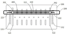
图标:100-定位板;111-一类定位孔;112-二类定位孔;113-额外设置的二类定位孔;121-标尺左定位槽;122-标尺右定位槽;131-标尺左定位槽刻度;132-标尺右定位槽刻度;200-标尺;210-标尺定位孔;221-标尺左基准线;222-标尺右基准线;301-左螺丝;302-右螺丝;400-新增投影机适配位置;501-左投影机;502-右投影机。Icons: 100-positioning plate; 111-first-class positioning hole; 112-second-class positioning hole; 113-additional second-class positioning hole; 121-ruler left positioning slot; 122-ruler right positioning slot; 131-ruler left positioning Slot scale; 132-ruler right positioning groove scale; 200-ruler; 210-ruler positioning hole; 221-ruler left reference line; 222-ruler right reference line; 301-left screw; 302-right screw; 400-new projection 501-left projector; 502-right projector.
应该理解上述附图只是示意性的,并没有按比例绘制。It should be understood that the above drawings are schematic only and are not drawn to scale.
具体实施方式Detailed ways
图1为本实施例提供的用于光场扩展的投影机阵列定位装置的结构示意图。该用于光场扩展的投影机阵列定位装置包含定位板100及标尺200。FIG. 1 is a schematic structural diagram of a projector array positioning device for light field expansion according to this embodiment. The projector array positioning device for light field expansion includes a
定位板100上具有若干一类定位孔111及若干二类定位孔112;定位板100上具有标尺左定位槽121及标尺右定位槽122;标尺左定位槽121设置有标尺左定位槽刻度131,标尺右定位槽122设置有标尺右定位槽刻度132。The
一类定位孔111为长宽一致开孔,其在定位板100上一维排列。现有投影光场系统的投影机均安装于一类定位孔111所在位置。The first type of
二类定位孔112为长宽不一致开孔,其设置于两个相邻一类定位孔111的中垂线上;二类定位孔112排列方向与一类定位孔111排列方向一致,且其开孔长轴方向与一类定位孔111排列方向垂直。The second-
标尺左定位槽121及标尺右定位槽122均为长宽不一致开孔,标尺左定位槽121位于标尺右定位槽122左侧。The ruler left
标尺左定位槽刻度131及标尺右定位槽刻度132,用于示出具有不同结构参数q的现有投影光场显示系统其在进行光场扩展时的新增投影机适配位置400。对任意现有投影光场显示系统,设其投影机到一维逆反射幕布的距离为l,其投影图像的宽度为d,则其结构参数q=l/d。设一类定位孔所在直线与左右定位槽的交点为左右原点,标尺左右定位槽刻度分别距离左右原点位移为k位置的刻度,其对应的光学系统应具有的结构参数q满足k =g×q,其中g为一类定位孔111节距,本实施例中g=6 cm。此时,在任意k位置处,标识数值为k/g,则其数值直接等于结构参数q,以方便用户进行使用。The scale left
标尺200上具有1个标尺定位孔210;标尺200上设置有标尺左基准线221及标尺右基准线222。The
标尺定位孔210为一长宽不一致开孔,其开孔长轴方向与一类定位孔111排列方向一致。标尺左基准线221及标尺右基准线222与标尺定位孔210长轴方向一致,用于表示标尺定位孔210长轴的中轴线位置。The
请参考图2,本用于光场扩展的投影机阵列定位装置按照如下方式使用。Referring to FIG. 2 , the projector array positioning device for light field expansion is used in the following manner.
1、用户测得现有投影光场显示系统的结构参数q;1. The user measures the structural parameter q of the existing projection light field display system;
若现有投影光场显示系统中,投影机到一维逆反射幕布的距离l= 2 m,其投影图像的宽度为d=1 m,则其结构参数q= l/d=2。If in the existing projection light field display system, the distance from the projector to the one-dimensional retroreflective screen is l = 2 m, and the width of the projected image is d = 1 m, then its structural parameter q = l / d = 2.
2、移动标尺200并通过刻度对准,使标尺左基准线221与定位板100上标尺左定位槽刻度131对应结构参数为q的位置重合,并使标尺右基准线222与定位板100上标尺右定位槽刻度132对应结构参数为q的位置重合;2. Move the
因本实施例中g=6 cm,标尺左右定位槽刻度分别距离左右原点位移为k位置的刻度标识数值为k/g;即k=6 cm位置上,标识数值为1;k=12 cm位置上,标识数值为2。Because g =6 cm in the present embodiment, the scale mark value of the left and right positioning groove scale of the ruler is respectively k/g from the left and right origin displacement to be k position; That is, on the k =6 cm position, the mark value is 1; k =12 cm position , the identification value is 2.
因此,使标尺左基准线221与定位板100上标尺左定位槽刻度131值为2的位置重合,并标尺右基准线222与定位板100上标尺右定位槽刻度132值为2的位置重合。Therefore, the
3、通过一作为紧固件的左螺丝301穿过标尺定位孔210及标尺左定位槽121并固定,并通过作为另一紧固件的右螺丝302穿过标尺定位孔210及标尺右定位槽122并固定,以此固定标尺200和定位板100的相对位置。3. Use a
4、标尺定位孔210开口与第二类定位孔112开口的重合位置则是适应于当前现有投影光场显示系统进行光场扩展时的新增投影机适配位置400。4. The overlapping position of the opening of the
请参考图3和图4本用于光场扩展的投影机阵列定位装置的工作原理为:Please refer to Figure 3 and Figure 4. The working principle of the projector array positioning device for light field expansion is as follows:
对平行排列的两台相邻投影机,即左投影机501及右投影机502,其发射的光束经逆反射后汇聚于投影机原各自所在位置。显而易见的,左投影机501及右投影机502之间的位置将少有光线覆盖。For two adjacent projectors arranged in parallel, that is, the
请参考图3,此时,在左投影机501最右投影光束和右侧投影机502最左投影光束的交点位置设置新增投影机时,则其逆反射光线可以恰好覆盖两台投影机之间的空间范围,因此其可以达到信息最优条件。此时,具体的,若投影机其到一维逆反射幕布的距离为l,其投影图像的宽度为d,两台投影机的间距为g,在左投影机501最右投影光束和右侧投影机502最左投影光束的交点位置设置新增投影机时,则根据相似三角形关系,原有两台投影机所在直线到新增投影机之间的距离k有k= g×l/d,即以该参数k对新增投影机适配位置400进行标识即可。具体的,可在定位板100上设置二类定位孔112对新增投影机适配位置400进行约束。Please refer to FIG. 3 , at this time, when a new projector is set at the intersection of the rightmost projection beam of the
进一步的,请参考图4,若在左侧投影机501最左投影光束和右侧投影机502最右投影光束的交点位置设置新增投影机,则其逆反射光线也可以恰好覆盖两台投影机之间的空间范围,因此其也可以达到信息最优条件。同理,在左投影机501最左投影光束和右投影机502最右投影光束的交点位置设置新增投影机时,同样根据相似三角形关系,原有两台投影机所在直线到新增投影机之间的距离k也有k= g×l/d,即以该参数k对新增投影机适配位置400进行标识即可。具体的,可通过定位板100上额外设置的二类定位孔113对新增投影机适配位置400进行约束。Further, please refer to FIG. 4, if a new projector is set at the intersection of the leftmost projection beam of the
综上所述,本发明只需要让用户测得现有投影光场显示系统的结构参数,并需根据现有投影光场显示系统的结构参数将标尺200放置于对应刻度线位置,则可方便地确定新增投影机适配位置400,同时标尺定位孔210开口与第二类定位孔112开口的重合位置方便其固定新增投影机,便于其进行光场扩展。To sum up, the present invention only needs to allow the user to measure the structural parameters of the existing projection light field display system, and needs to place the
Claims (2)
Priority Applications (1)
| Application Number | Priority Date | Filing Date | Title |
|---|---|---|---|
| CN202210257235.3A CN114326273B (en) | 2022-03-16 | 2022-03-16 | A projector array positioning device for light field expansion |
Applications Claiming Priority (1)
| Application Number | Priority Date | Filing Date | Title |
|---|---|---|---|
| CN202210257235.3A CN114326273B (en) | 2022-03-16 | 2022-03-16 | A projector array positioning device for light field expansion |
Publications (2)
| Publication Number | Publication Date |
|---|---|
| CN114326273A CN114326273A (en) | 2022-04-12 |
| CN114326273B true CN114326273B (en) | 2022-05-13 |
Family
ID=81033633
Family Applications (1)
| Application Number | Title | Priority Date | Filing Date |
|---|---|---|---|
| CN202210257235.3A Active CN114326273B (en) | 2022-03-16 | 2022-03-16 | A projector array positioning device for light field expansion |
Country Status (1)
| Country | Link |
|---|---|
| CN (1) | CN114326273B (en) |
Family Cites Families (17)
| Publication number | Priority date | Publication date | Assignee | Title |
|---|---|---|---|---|
| US20050151941A1 (en) * | 2000-06-16 | 2005-07-14 | Solomon Dennis J. | Advanced performance widget display system |
| US7028899B2 (en) * | 1999-06-07 | 2006-04-18 | Metrologic Instruments, Inc. | Method of speckle-noise pattern reduction and apparatus therefore based on reducing the temporal-coherence of the planar laser illumination beam before it illuminates the target object by applying temporal phase modulation techniques during the transmission of the plib towards the target |
| US7140543B2 (en) * | 2000-11-24 | 2006-11-28 | Metrologic Instruments, Inc. | Planar light illumination and imaging device with modulated coherent illumination that reduces speckle noise induced by coherent illumination |
| EP1470727A2 (en) * | 2002-01-04 | 2004-10-27 | Neurok, LLC | Three-dimensional image projection employing retro-reflective screens |
| DE10240381A1 (en) * | 2002-08-31 | 2004-03-11 | Schrodt, Stefan | Compensation of the projection and optic axes for projections with several projectors to improve the congruence |
| JP4652727B2 (en) * | 2004-06-14 | 2011-03-16 | キヤノン株式会社 | Stereoscopic image generation system and control method thereof |
| TWI537605B (en) * | 2014-08-28 | 2016-06-11 | 台達電子工業股份有限公司 | Autostereoscopic display device and autostereoscopic display method using the same |
| CN104469344B (en) * | 2014-12-03 | 2017-03-01 | 北京智谷技术服务有限公司 | Light field display control method and device, light field display device |
| CN105043304A (en) * | 2015-09-15 | 2015-11-11 | 沈阳飞机工业(集团)有限公司 | Novel calibration plate and calibration method for performing length measurement by using calibration plate |
| CN106918974B (en) * | 2015-12-24 | 2019-05-03 | 深圳光峰科技股份有限公司 | Projection device, optical projection system and its correcting and regulating method |
| CN106791335B (en) * | 2017-01-25 | 2019-05-14 | 浙江大学 | A compact large-view light field acquisition system and its analysis and optimization method |
| CN109557666B (en) * | 2017-09-27 | 2023-05-23 | 北京翠鸟视觉科技有限公司 | Near-eye optical imaging system, near-eye display device and head-mounted display device |
| CN108803054B (en) * | 2018-06-06 | 2020-06-19 | 北京邮电大学 | 3D light field display system |
| CN109521576A (en) * | 2018-12-06 | 2019-03-26 | 成都工业学院 | A kind of stereo projection apparatus |
| CN110009693B (en) * | 2019-04-01 | 2020-12-11 | 清华大学深圳研究生院 | Rapid blind calibration method of light field camera |
| CN110058420A (en) * | 2019-04-08 | 2019-07-26 | 成都工业学院 | A kind of reflex reflection stereo projection display apparatus |
| CN113917701B (en) * | 2021-12-14 | 2022-02-18 | 成都工业学院 | A projection light field stereoscopic display device |
-
2022
- 2022-03-16 CN CN202210257235.3A patent/CN114326273B/en active Active
Also Published As
| Publication number | Publication date |
|---|---|
| CN114326273A (en) | 2022-04-12 |
Similar Documents
| Publication | Publication Date | Title |
|---|---|---|
| CN106996783B (en) | A kind of intelligent matching method and device of driving trajectory and road network base map | |
| TWI741904B (en) | Measuring system and measuring method | |
| US8919001B2 (en) | Method and system for helping to position a component on a structural element | |
| CN103324007B (en) | A kind of method that masterplate is projected on workpiece | |
| CN111340890A (en) | Camera external parameter calibration method, device, device and readable storage medium | |
| JP2018014553A (en) | Information processing apparatus, information processing method, and program | |
| JP2017181342A (en) | Summing-out support device and summing-out support method | |
| CN111829461B (en) | Positioning target, vision measurement system and method for acquiring flatness | |
| CN114326273B (en) | A projector array positioning device for light field expansion | |
| KR102595365B1 (en) | System and method for analyzing slope condition based on internet on things technique | |
| CN103793113A (en) | Imaging locating method of optical touch module and optical touch control equipment | |
| CN106600561B (en) | Aerial image perspective distortion automatic correction method based on projection mapping | |
| CN101581580A (en) | Spatial digitalized method and spatial digitalized device for land measurement | |
| JP2013122429A (en) | Method for evaluating production error | |
| JP7774805B2 (en) | Structure management method and structure management system | |
| WO2018061900A1 (en) | Three-dimensional measurement system and three-dimensional measurement method | |
| JP2013024579A (en) | Optical position detector and display system with input function | |
| CN110389494A (en) | The measuring method of laser aid and its laser projection pattern dimension | |
| US20170351240A1 (en) | Installation Position Pointer System | |
| EP4524888A1 (en) | Crawl approach for creation and automatic annotation of custom datasets | |
| CN113419407A (en) | Matching method of compound eye lighting system | |
| US10901427B2 (en) | Measurement assembly and positioning system | |
| JP2014041500A (en) | Matching support device, matching support method, and program thereof | |
| CN113027075A (en) | Line marking device and line marking method | |
| CN104061901A (en) | Method and system for measuring stereo distance |
Legal Events
| Date | Code | Title | Description |
|---|---|---|---|
| PB01 | Publication | ||
| PB01 | Publication | ||
| SE01 | Entry into force of request for substantive examination | ||
| SE01 | Entry into force of request for substantive examination | ||
| GR01 | Patent grant | ||
| GR01 | Patent grant |