CN114323059A - Road characterization method, device and equipment - Google Patents
Road characterization method, device and equipment Download PDFInfo
- Publication number
- CN114323059A CN114323059A CN202111670979.XA CN202111670979A CN114323059A CN 114323059 A CN114323059 A CN 114323059A CN 202111670979 A CN202111670979 A CN 202111670979A CN 114323059 A CN114323059 A CN 114323059A
- Authority
- CN
- China
- Prior art keywords
- road
- information
- intersection
- discrete
- discrete points
- Prior art date
- Legal status (The legal status is an assumption and is not a legal conclusion. Google has not performed a legal analysis and makes no representation as to the accuracy of the status listed.)
- Granted
Links
- 238000012512 characterization method Methods 0.000 title claims abstract description 42
- 238000000034 method Methods 0.000 claims abstract description 30
- 230000009471 action Effects 0.000 claims description 8
- 238000010586 diagram Methods 0.000 description 12
- 238000012790 confirmation Methods 0.000 description 11
- 238000004891 communication Methods 0.000 description 9
- 241001417527 Pempheridae Species 0.000 description 5
- 238000012545 processing Methods 0.000 description 5
- 230000002457 bidirectional effect Effects 0.000 description 4
- 230000008569 process Effects 0.000 description 4
- 241000283070 Equus zebra Species 0.000 description 3
- 230000006399 behavior Effects 0.000 description 3
- 230000008859 change Effects 0.000 description 3
- 230000006870 function Effects 0.000 description 3
- 230000009286 beneficial effect Effects 0.000 description 2
- 101100400452 Caenorhabditis elegans map-2 gene Proteins 0.000 description 1
- 230000001133 acceleration Effects 0.000 description 1
- 230000004888 barrier function Effects 0.000 description 1
- 238000004140 cleaning Methods 0.000 description 1
- 238000005516 engineering process Methods 0.000 description 1
- 238000002955 isolation Methods 0.000 description 1
- 238000010295 mobile communication Methods 0.000 description 1
- 238000012986 modification Methods 0.000 description 1
- 230000004048 modification Effects 0.000 description 1
- 238000003032 molecular docking Methods 0.000 description 1
- 239000007787 solid Substances 0.000 description 1
- 230000003068 static effect Effects 0.000 description 1
- 238000006467 substitution reaction Methods 0.000 description 1
- 230000001502 supplementing effect Effects 0.000 description 1
- 238000010408 sweeping Methods 0.000 description 1
Images


Landscapes
- Traffic Control Systems (AREA)
- Navigation (AREA)
Abstract
The invention relates to the technical field of unmanned driving, in particular to a road characterization method, a road characterization device and road characterization equipment. According to the road characterization method, the road characterization device and the road characterization equipment, the road corresponding to the target path is characterized through the lane central line and the lane edge line formed by the discrete points and the connecting lines among the discrete points, the target path is displayed in application, the road characterization complexity is reduced, the complete multi-lane road condition is supported, and the method, the device and the equipment are more suitable for being used by unmanned vehicles.
Description
Technical Field
The invention relates to the technical field of unmanned driving, in particular to a road characterization method, a road characterization device and road characterization equipment.
Background
Route planning is an important part of unmanned driving, and its task is to find a travelable and safe route from a starting point to an end point. When the path planning is performed, the road information of the current environment needs to be represented in advance, so that the path planning program of the vehicle knows how to walk in the current environment. The currently common road representation modes include an optional map and a dotting map, wherein the optional map uses an analytic expression to represent the shape of a lane, and the dotting map adds a custom attribute on a track point to represent the lane. These maps define the three-dimensional shape of each lane, the shape of the lane lines, and the location of some static objects on the road.
For an unmanned vehicle, the route quality of a dotting map is not high enough, and the complete multi-lane route condition cannot be supported; the openrive map is too large, the contained contents are very much, the map loading speed is very slow, the drawing cost is very high, the unmanned vehicle does not need to use so much environment information when performing tasks, and only needs to know how to walk in the current environment, so that much information for describing the environment state contained in the map is useless, the map definition of the information is complex and can occupy a large amount of memory, and the utilization rate of the map information by the unmanned vehicle is not high.
Disclosure of Invention
The embodiment of the invention mainly solves the technical problem that the existing road representation mode is not suitable for being used by unmanned vehicles.
In order to solve the above technical problem, one technical solution adopted by the embodiment of the present invention is: a method of road characterization is provided, the method comprising:
obtaining at least one target path, wherein the target path comprises a lane central line and a lane edge line which are formed by a plurality of discrete points;
acquiring the road attribute information of the discrete points and acquiring the road type information of the roads corresponding to the discrete points;
determining an intersection area according to the road attribute information and the road type information, and acquiring intersection information of intersections corresponding to the discrete points of the intersection area;
determining connection information of discrete points of each target path;
and representing the road according to the road attribute information, the road type information, the intersection information and the connecting line information.
Optionally, the road attribute information specifically includes:
position information, which is the position of the discrete point;
speed information, which is the speed of the vehicle passing through the discrete points;
direction information, which is the direction of the vehicle passing through the discrete points;
the vehicle running action information is a running action requirement when the vehicle passes through the discrete point;
and the vehicle driving road condition information is the road condition near the discrete point.
Optionally, the acquiring the road type information of the road corresponding to the discrete point includes:
and determining the road type of the road corresponding to the discrete point according to the road attribute information of the discrete point and by combining a preset road type table.
Optionally, the determining an intersection region according to the road attribute information and the road type information, and acquiring intersection information of an intersection corresponding to the discrete point of the intersection region includes:
determining a single-way end region based on the road attribute information and the road type information, wherein the single-way end region comprises the discrete points corresponding to the ends of the target path;
determining an intersection area according to the position relation of the single-path end area, wherein the intersection area comprises at least two single-path end areas with adjacent position relations;
and acquiring intersection information of the intersection corresponding to the discrete points of the intersection region based on the road attribute information of the discrete points corresponding to the intersection region.
Optionally, the acquiring intersection information of the intersection corresponding to the discrete point in the intersection region:
and determining the intersection type of the intersection region corresponding to the discrete point by combining a preset intersection type table according to the road attribute information of the discrete point.
Optionally, the determining the connection information of the discrete point of each target path includes:
acquiring the position information and the direction information of the discrete point in the target path;
and determining the connection information of the discrete points according to the position information and the direction information, wherein the connection information is used for representing the path direction of the adjacent discrete points.
Optionally, the characterizing the road according to the road attribute information, the road type information, the intersection information, and the link information includes:
and displaying the target path, wherein the target path comprises a lane central line and a lane edge line which are formed by a plurality of discrete points, and a connecting line for connecting the discrete points, the discrete points are attached with road attribute information and road type information corresponding to roads, and the discrete points in the intersection area are attached with the corresponding intersection information.
Optionally, the method further includes:
acquiring object attribute information of a special object in a road corresponding to the target path;
and binding the special object to a corresponding road or a corresponding intersection region in a polygonal form based on the object attribute information.
Optionally, the method further includes:
displaying the special object in the form of a polygon, wherein the polygon is attached with the corresponding object attribute information.
In order to solve the above technical problem, another technical solution adopted by the embodiment of the present invention is: providing a road characterization device, the device comprising:
the target path acquisition module is used for acquiring at least one target path, and the target path comprises a lane central line and a lane edge line which are formed by a plurality of discrete points;
the road information acquisition module is used for acquiring the road attribute information of the discrete points and acquiring the road type information of the roads corresponding to the discrete points;
the intersection information acquisition module is used for determining an intersection area according to the road attribute information and the road type information and acquiring intersection information of an intersection corresponding to the discrete point of the intersection area;
the link information acquisition module is used for determining link information of discrete points of each target path;
and the road representation module is used for representing the road according to the road attribute information, the road type information, the intersection information and the connecting line information.
In order to solve the above technical problem, another technical solution adopted by the embodiment of the present invention is: there is provided a road characterization apparatus comprising:
at least one processor;
a memory communicatively coupled to the at least one processor;
wherein the memory stores instructions executable by the at least one processor to enable the at least one processor to perform the method described above.
The road characterization method, the device and the equipment provided by the embodiment of the invention are different from the related technology, the road corresponding to the target path is characterized by the lane central line and the lane edge line formed by the discrete points and the connecting line between the discrete points, and the target path is displayed in the application, so that the road characterization complexity is reduced, the complete multi-lane road condition is supported, and the method, the device and the equipment are more suitable for being used by unmanned vehicles.
Drawings
One or more embodiments are illustrated in drawings corresponding to, and not limiting to, the embodiments, in which elements having the same reference number designation may be represented as similar elements, unless specifically noted, the drawings in the figures are not to scale.
Fig. 1 is a schematic flow chart of a road characterization method according to an embodiment of the present invention;
fig. 2a is an exemplary diagram of a discrete map provided by an embodiment of the present invention, fig. 2b is a schematic diagram at a in the discrete map 2a, fig. 2c is an exemplary diagram of another discrete map provided by an embodiment of the present invention, and fig. 2d is a simple schematic diagram of the discrete map 2 c;
FIG. 3 is an exemplary diagram of road attribute information for discrete points in an embodiment of the present invention;
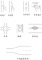
FIG. 4 is an illustration of road type representation in an embodiment of the present invention;
FIG. 5a is an example of a road type of a highway; fig. 5b is an example of a road type of a country road, fig. 5c is an example of a road type of an urban road, fig. 5d is an example of a road type of an entrance and an exit of an expressway, fig. 5e is an example of a road type of two interconnected expressways, and fig. 5f is an example of a road type to be specially set;
fig. 6 is a schematic flow chart illustrating a process of determining an intersection region and acquiring intersection information according to an embodiment of the present invention;
FIG. 7 is an illustration of intersection type representations in an embodiment of the present invention;
FIG. 8 is an exemplary diagram of some intersection regions in an embodiment of the invention;
FIG. 9 is an illustration of a special object representation in an embodiment of the invention;
FIG. 10 is a schematic diagram of a road characterization device provided by an embodiment of the present invention;
fig. 11 is a block diagram of a road representation apparatus according to an embodiment of the present invention.
Detailed Description
In order to make the objects, technical solutions and advantages of the present invention more apparent, the present invention is described in further detail below with reference to the accompanying drawings and embodiments. It should be understood that the specific embodiments described herein are merely illustrative of the invention and are not intended to limit the invention.
It should be noted that, if not conflicted, the various features of the embodiments of the invention may be combined with each other within the scope of protection of the invention. Additionally, while functional block divisions are performed in the device diagrams, with logical sequences shown in the flowcharts, in some cases, the steps shown or described may be performed in a different order than the block divisions in the device diagrams, or the flowcharts.
Unless defined otherwise, all technical and scientific terms used herein have the same meaning as commonly understood by one of ordinary skill in the art to which this invention belongs. The terminology used in the description of the invention herein is for the purpose of describing particular embodiments only and is not intended to be limiting of the invention. As used herein, the term "and/or" includes any and all combinations of one or more of the associated listed items. Furthermore, the technical features mentioned in the different embodiments of the invention described below can be combined with each other as long as they do not conflict with each other.
An embodiment of the present invention provides a road characterization method, please refer to fig. 1, fig. 2a, and fig. 2b, which includes the following steps:
s11, obtaining at least one target path, wherein the target path comprises a lane central line and a lane edge line which are formed by a plurality of discrete points. The target path can correspond to all roads in the target range, namely the roads in the target range can have lane central lines and lane edge lines formed by corresponding discrete points, wherein the current driving lane can be judged according to the lane central lines when the unmanned vehicle actually runs, the lane edge lines can represent the range of the lane, and the maximum driving deviation range of the unmanned vehicle during the driving without changing the lane can be planned. In some special cases, if a road is not suitable to be represented by using the lane center line, the target path corresponding to the road may only include the lane edge line, but not the lane center line. Each target path at least comprises two discrete points with different positions, each discrete point comprises road attribute information corresponding to the discrete point and road type information corresponding to the road, the road attribute information is used for describing the positions, the directions, the road conditions and other information of all roads in a target range, and the road type information is used for describing the road types of the roads corresponding to the discrete points.
Referring to fig. 2a and 2c, fig. 2a and 2c illustrate an example of a manner in which a target route is presented in an application, that is, the application may be presented to a user in the form of a discrete map, the target route, in combination with a map coordinate system, forms a discrete map for representing roads, and the position coordinates of each discrete point in the discrete map are fixed. Fig. 2c is a schematic diagram of the intersection region. Referring to fig. 2b and fig. 2d, fig. 2b is an enlarged schematic view of a point a in fig. 2a, as an example in fig. 2b, where a road includes four lanes, which are respectively distinguished by a, b, c and d, and fig. 2d is a simple schematic view of a center line and a road edge line of the road in fig. 2 c. For ease of understanding, the lane edge lines are shown in solid lines and the lane center lines are shown in dashed lines in fig. 2b and 2d, and in an actual discrete map, both the lane edge lines and the lane center lines are formed of discrete points.
And S12, acquiring the road attribute information of the discrete points and acquiring the road type information of the roads corresponding to the discrete points. The road attribute information and the road type information can help to represent the corresponding road and assist the vehicle in path planning. Wherein the road attribute information includes location information, the location information being used to characterize the location of the discrete point.
The road attribute information includes position information and direction information, and specifically, the position information is the position of the discrete point; the direction information is a direction corresponding to a road, the position information and the direction information are specifically represented in the discrete map as position coordinates (x, y, θ) of the discrete point, specifically refer to an exemplary map of road attribute information corresponding to a certain discrete point shown in fig. 3, and the position coordinates (x, y, θ) are represented in fig. 3 as x, y, yaw and values thereof, where x is used to describe an abscissa corresponding to the discrete point in a coordinate system of the discrete map, a value range is (-inf, inf), inf represents infinity; y is used for describing the corresponding vertical coordinate of the discrete point in the coordinate system of the discrete map, and the value range is (-inf, inf); theta, yaw and its value in fig. 3, is used to describe the direction information of the discrete point corresponding to the road, specifically, the included angle between the road direction or lane direction and the x-axis of the coordinate system of the discrete map, and the value range is (-180,180%).
In addition to the above position information and direction information, the road attribute information also includes speed information, which is a speed limit of the vehicle when corresponding to the road, and is represented as speed min limit, speed max limit, and direction and values thereof in fig. 3. Wherein the speed min limit is the minimum speed of the vehicle on the road, and the value range is [0, inf); the speed max limit is the maximum driving speed of the vehicle on the road, and the value range is [0, inf); the direction is a speed direction of the vehicle on the road, and is 0 or 1, specifically, 0 indicates that the vehicle needs to run in the forward direction on the lane, and 1 indicates that the vehicle needs to run in the reverse direction on the lane. For example, the speed min limit value, speed max limit value and direction value of the discrete points illustrated in fig. 3 are 0, 36 and 0, respectively, the speed unit set in this embodiment is km/h, which indicates that the road corresponding to the discrete points has a minimum speed of 0 and a maximum speed of 36km/h, and it is required to travel in the forward direction, which indicates that the unmanned vehicle can pass through the road at any speed between 0 and 36km/h when performing a travel task, and the speed may be 0, i.e., the unmanned vehicle is allowed to stop at the road, but cannot travel in the reverse direction.
Optionally, the road attribute information further includes vehicle driving action information and vehicle driving road condition information. Specifically, the vehicle driving action information is a driving action requirement when the vehicle passes through a corresponding road, and the vehicle driving action information may include vehicle obstacle avoidance mode information, warehousing route confirmation information, check point confirmation information, turn light selection information, whistle selection information, and the like.
The vehicle obstacle avoidance mode information includes an obstacle avoidance mode when the vehicle passes through the road and an obstacle avoidance behavior when the vehicle passes through the road, such as the avoid mode and the near in fig. 3 and values thereof. The avoid mode and the value thereof are an obstacle avoidance mode when the vehicle passes through the road, the value range is an integer in [0,3], specifically, 0 represents that the vehicle is allowed to avoid the obstacle and can retreat when passing through the road, 1 represents that the vehicle is allowed to avoid the obstacle but cannot retreat when passing through the road, for example, the vehicle can detour the obstacle, 2 represents that the vehicle is not allowed to avoid the obstacle but can retreat when passing through the road, for example, the vehicle slightly retreats to keep a safe distance, and 3 represents that the vehicle is not allowed to avoid the obstacle and cannot retreat when passing through the road; the near and the value thereof are obstacle avoidance behaviors that the vehicle can take when passing through the road, and the value is 0 or 1 or 2, specifically, 0 represents that the vehicle can normally avoid obstacles to the left or to the right when passing through the road, 1 represents that the vehicle tends to avoid obstacles to the right when passing through the road, and 2 represents that the vehicle tends to avoid obstacles to the left when passing through the road, for example, the avoid mode value at the discrete point corresponding to the road illustrated in fig. 3 is 0, and the near value is 2, which represents that the vehicle can have obstacle avoidance behaviors and can retreat when driving to the road, and tends to avoid obstacles to the left when encountering obstacles.
The warehousing path confirmation information may help the vehicle to determine whether the discrete point belongs to a warehousing path, where the warehousing path indicates a path where the vehicle returns to a parking position, for example, an is parking node and a value thereof in fig. 3, where a value is 0 or 1, specifically, 0 indicates that the discrete point does not belong to a warehousing path, and 0 indicates that the discrete point belongs to a warehousing path.
In the process that the unmanned vehicle executes the task, in order to better judge whether the vehicle normally executes the task, a check point may be set on a necessary path, the check point confirmation information may help the vehicle to judge whether the discrete point is a check point, which is represented as is check point and its value in fig. 3, where the check point indicates that the vehicle needs to travel to the check point in the process of executing the task, and the check point may continue traveling, and the value is 0 or 1, specifically, 0 indicates that the discrete point is not a check point, and 1 indicates that the discrete point is a check point.
The turn signal selection information indicates whether and how the turn signal should be turned when the vehicle passes through the discrete point, for example, turning and its value in fig. 3 are set to 0 or 1 or 2, specifically, 0 indicates that the turn signal is not required to be turned when the vehicle travels to this point, 1 indicates that the left turn signal should be turned when the vehicle travels to this point, and 2 indicates that the right turn signal should be turned when the vehicle travels to this point.
The whistle selection information is a whistle requirement when the vehicle passes through the whistle selection information, for example, horn and its value in fig. 3 take a value of 0 or 1, specifically, 0 means that the vehicle does not whistle when the vehicle travels to the whistle selection information, and 1 means that the vehicle needs to whistle when the vehicle travels to the whistle selection information.
Specifically, the vehicle driving road condition information is used to represent the road condition near the discrete point, and the vehicle driving road condition information may include signal lamp indication information, parking area confirmation information, intersection confirmation information, lane information, special section confirmation information, and the like.
The signal light indication information indicates whether there is a traffic signal light and how the vehicle travels according to the indication information of the traffic signal light when passing through, for example, traffic light stop point and its value in fig. 3, the value range is an integer in [0,3], specifically, 0 indicates that there is no traffic signal light, 1 indicates that there is a traffic signal light and the vehicle travels according to the indication of the left turn signal light when passing through this point, 2 indicates that there is a traffic signal light and the vehicle travels according to the indication of the straight running light when passing through this point, 3 indicates that there is a traffic signal light and the vehicle travels according to the indication of the right turn signal light when passing through this point.
The parking area confirmation information describes whether the corresponding road belongs to a parking rod area, and the parking rod area represents an entrance and an exit of a parking area such as a garage or a temporary parking lot, and vehicles often come in and go out when possible. In fig. 3, the parking area confirmation information is represented as is parking rod and a value thereof, where the value is 0 or 1, specifically, 0 represents that the parking rod does not belong to the parking rod area, and 1 represents that the parking rod is a parking rod area, and when the vehicle travels to this place, there may be a special traveling requirement, for example, to avoid causing traffic jam, the vehicle cannot park at this place, and the like.
The intersection confirmation information represents the type of the road section of the corresponding road, and comprises the steps of judging whether the discrete point belongs to the intersection area or not and judging the type of the intersection. For example, the value of the road type and the value thereof in fig. 3 is 0 or 1 or 2, specifically, 0 represents that the discrete point is a normal straight road section, 1 represents that the discrete point is an intersection, and 2 represents that the discrete point is a T-shaped intersection.
The lane information indicates the number of lanes corresponding to the discrete point on the road, for example, the left lanes number and the value thereof in fig. 3, indicates the number of lanes on the left side of the lane where the discrete point is located, and the value range is an integer in [0,5 ]; the number of right lanes and the value of the number of right lanes represent the number of lanes on the right side of the lane where the discrete point is located, and the value range is an integer in [0,5 ]. The left lanes number and the right lanes number at the discrete points illustrated in fig. 3 both have a value of 0, which indicates that the road corresponding to the discrete points is a one-way road and a one-way road segment, and the vehicle can only travel in the lane.
The special link confirmation information describes whether the road corresponding to the discrete point is a special link, for example, the road crossswap and the value of the road crossswap in fig. 3 indicate whether the discrete point belongs to a zebra crossing region, and the value is 0 or 1, specifically, 0 indicates that the discrete point is not a zebra crossing region, and 1 indicates that the discrete point is a zebra crossing region; the road attribute and its value in fig. 3 indicate whether the discrete point is a special road segment, and the value is 0 or 1. Specifically, 0 indicates that the discrete point does not belong to a special link, 1 indicates that the discrete point belongs to a special link, and specifically, what special link is set according to the actual situation, for example, if there is a school near the road, setting 1 indicates that the discrete point belongs to a school link.
In some other embodiments, the vehicle driving road condition information may further include task type information, where the task type information indicates task attributes corresponding to different types of work tasks, and due to different task properties performed by different vehicles, most vehicles need to perform point-to-point movement when performing tasks, for example, a logistics vehicle moves from a starting point to an end point; while other specialized vehicles do not necessarily have to be point-to-point while performing tasks, such as sweepers moving along roadsides and sweeping the road while performing work tasks. Taking a sweeper as an example, the sweeper needs to move along the edge when executing a task, the value of task type and the value thereof in fig. 3 is 0 or 1, specifically, 0 represents that the discrete point is a discrete point corresponding to a point-to-point movement task, and 1 represents that the discrete point is a discrete point corresponding to a sweeper edge-extending cleaning task. It should be noted that the task type information includes, but is not limited to, a point-to-point movement task and a edgewise movement task, and may also be a special travel task corresponding to another unmanned vehicle.
In some other embodiments, the vehicle driving road condition information may further include re-planning information, where the re-planning information may help the vehicle to determine whether the discrete point corresponds to the road allows re-path planning when performing path planning, for example, it is represented as an is can replan and its value in fig. 3, where the value is 0 or 1, specifically, 0 represents that re-planning is allowed at the place when planning the path, and 1 represents that re-planning is not allowed at the place when planning the path.
The vehicle described in this embodiment includes a sweeper, a logistics vehicle, a docking vehicle, or any other unmanned vehicle.
The acquiring the road type information of the road corresponding to the discrete point specifically includes: and determining the road type of the road corresponding to the discrete point according to the road attribute information of the discrete point and by combining a preset road type table. Referring to fig. 4, fig. 4 is an exemplary diagram of a road type table in an embodiment of the present invention, in a discrete map representing a road, the discrete point further includes road type information of the road corresponding to the discrete point, and a sequence number corresponding to the road type may be recorded by referring to table contents in fig. 4. Specifically, the road type may refer to fig. 4, for example, if a road corresponding to a certain discrete point is a road normally available for driving in a city, that is, real driving in fig. 4, serial number 1 may be recorded to the road type information of the discrete point, which indicates that the road corresponding to the discrete point is a road available for driving and wired on the ground, and the road is not of another road type; for another example, the road type of a certain discrete point corresponding to a road is a bus lane, and corresponds to bus in the table of fig. 4, that is, the road type information of the discrete point may be recorded as 5.
Referring to fig. 5a to 5f in conjunction, fig. 5a to 5f illustrate a portion of the roadway type of fig. 4, wherein the curb in fig. 5c represents a curb for isolating the median from the highway lane.
The virtual driving corresponding to the number 2 in fig. 4 indicates that the road is a road without a line on the ground, such as a one-way lane or a rural road without a marking line, for example, as shown in fig. 5a to 5 f. The path corresponding to the sequence number 3 indicates that the road is a road generated from a dotting map, wherein the dotting map is a map representing the road by connecting route points and route points. The tram corresponding to the number 4 indicates that the road is a light rail or a tram lane. And the bus corresponding to the serial number 5 represents that the road is a bus lane. The road types corresponding to the serial numbers 1 to 5 are common road types when representing roads, and are usually covered when presetting a road type table.
Biking, corresponding to the number 6, indicates that the road is a lane reserved for a change to a cyclist, such as the example in fig. 5 c. The Sidewalk corresponding to the number 7 indicates that the road is a road on which pedestrians are allowed to walk, such as the example in fig. 5 c. The parkking corresponding to the serial number 8 indicates that the road is a lane with Parking spaces, such as the example in fig. 5 c.
Stop corresponding to the number 9 indicates that the road is a hard shoulder of a highway for emergency stops, such as the example in fig. 5 a. The Shoulder corresponding to the number 10 indicates that the road is a soft boundary of the road edge, such as the examples in fig. 5a to 5 c. Border, numbered 11, indicates that the road is a hard Border around the edge of the road, and furthermore, the road has the same height as the normally available lane, such as the examples in FIGS. 5 a-5 c. The reserved corresponding to the sequence number 12 indicates that the road belongs to a lane on which no vehicle should travel, usually the lane has the same height as the lane of the road, and a solid line and a broken line are generally used to separate such roads, for example, as shown in fig. 5 b.
Left turn waiting area corresponding to the serial number 13 indicates that the road is a Left turn waiting area. The Straight waiting area corresponding to the serial number 14 indicates that the road is a Straight waiting area. The Median corresponding to the number 15 indicates that the road is a lane between lanes in different directions, and in cities, such a road is usually used to separate traffic in different directions on a large road, similar to a reference line (road on which a reference line is located) in an optional road map, such as a double yellow solid line or an isolation strip, for example, as shown in fig. 5 c.
The exit corresponding to the sequence number 16 indicates a lane where the road is parallel to the main road segment and is mainly used for deceleration, as in the examples of fig. 5d and 5 e. The entry corresponding to the number 17 indicates a lane where the road is parallel to the main road section and is mainly used for acceleration, such as the examples in fig. 5d and 5 e. The onramp corresponding to the number 18 indicates that the road is a ramp leading from a country or city road to an expressway, such as the expressway entrance illustrated in fig. 5 e. The offRamp corresponding to the number 19 indicates that the road is a ramp required to exit an expressway towards a country or urban road, such as the expressway shown in fig. 5 e. The connectingRamp corresponding to the number 20 indicates that the road is a ramp connecting two expressways, such as the expressway intersection illustrated in fig. 5 d. The types of roads corresponding to serial numbers 16 to 20 are more representative of road end areas located on expressways and used for connecting roads at different roads. It should be noted that the determination of the road type is not limited to the determination in the road type table shown in fig. 4, and fig. 4 is only an example of the road type table, and an appropriate road type table may be set according to different situations in practical application.
In other embodiments, the road type table may further reserve some road types to be set, such as serial numbers 21-23 in fig. 4, whose road types are recorded as special 1-special 3, for processing some special road types that are not yet defined, so as to cope with potential needs that may exist, and avoid the situation that a discrete point cannot obtain corresponding road type information because a corresponding serial number cannot be found. For example, if there is a road type in fig. 5f, which is not any of the above serial numbers 1-20, the road may be proposed as a new road type, i.e. bidirectional corresponding to the serial number 24 in fig. 4, which indicates that the road is a bidirectional lane. Note that, for convenience of understanding, a number 24 is added in fig. 4 to indicate bidirectional, but in an actual situation, a new road type may directly correspond to the number 21, and the road type corresponding to the number 21 is set as bidirectional.
S13, determining an intersection area according to the road attribute information and the road type information, and acquiring intersection information of the intersection corresponding to the discrete points of the intersection area. Referring to fig. 6, fig. 6 is a schematic flow chart illustrating a process of determining a road junction area and acquiring intersection information according to an embodiment of the present invention, where the determining a road junction area according to the road attribute information and the road type information and acquiring intersection information of an intersection corresponding to the discrete point in the road junction area includes:
s131, determining a single-way end region based on the road attribute information and the road type information, wherein the single-way end region comprises the discrete points corresponding to the road end of the target path. The road end is the end position of a road with the unchanged number of lanes.
S132, determining a crossing area according to the position relation of the single-way end area, wherein the crossing area comprises at least two single-way end areas with adjacent position relations. If the number of lanes of a road changes, for example, a single lane changes into a double lane, the single lane is a road, the double lane is another road, and the area where the number of lanes changes is a crossing area. If there is a physical obstacle in the middle of a road, the left and right parts of the obstacle are set as two different roads. The intersection region includes at least one of: the junction region of the adjacent road sections, the bifurcation region of a single lane to multiple lanes and the junction region of multiple lanes to a single lane are formed, wherein if at least two adjacent intersection regions exist, the at least two intersection regions are combined into one intersection region. When the intersection area is characterized, a polygon is constructed, the single-path end area of the intersection area is included as the polygon corresponding to the intersection area, and the discrete points included in the intersection area are the discrete points corresponding to the intersection area.
Referring to fig. 7, fig. 7 is an example of an intersection type table according to an embodiment of the present invention, similar to the road type table, the determination of the intersection type is not limited to the determination in the intersection type table shown in fig. 7, fig. 7 is only an example of an intersection type table, and an appropriate intersection type table may be set according to different situations in practical application. Similarly, the intersection type table is also provided with types to be set specifically, and the types are used for processing some special intersection types which are not defined yet so as to meet potential requirements which may exist.
S133, acquiring intersection information of the intersection corresponding to the discrete points of the intersection area based on the road attribute information of the discrete points corresponding to the intersection area. The intersection information includes intersection type information corresponding to the intersection region, and position information of the intersection region obtained based on the position information of the intersection including the discrete points, and the division of the intersection region in the road can refer to the example in fig. 2 c.
Regarding the example of dividing the road and the intersection region, please refer to fig. 8, the ramp 1 and the ramp 2 in fig. 8 can be regarded as a type of situation, the ramp entering the main road is an individual road, the intersection region is the place where the ramp and the main road meet, and the intersection type is the ramp entering or exiting.
In the example of the safety island in fig. 8, the safety island 1 belongs to the safety island located in the middle of the road, that is, the road is separated at the safety island and back converged behind the safety island, in this case, two roads before and after the safety island belong to two different roads, the intersection region is the intersection part where the safety island and the road meet, and the type of the intersection is the safety island; the safety island 2 in fig. 8 belongs to a safety island between a left-turn lane of an intersection, a straight lane of the intersection and a straight lane in front of the intersection, and the whole intersection belongs to an intersection area (including the safety island), and the type of the intersection is a protected intersection or an unprotected intersection.
In the roundabout example in fig. 8, the entire roundabout belongs to one intersection area, the intersection type is the roundabout, and the intersection area includes all the entrance sections of the roundabout and the roads on the roundabout.
In the example of the secondary road in fig. 8, the primary road and the secondary road are two roads, and the intersection is denoted as an intersection area, and the intersection type is the secondary road.
In the hatched line example in fig. 8, the blank part in the shown road is a road, the shaded part is a none, and the type of the road corresponding to the shaded part is a restart.
In the example of the change in the number of lanes in fig. 8, the road shown changes from a single lane road to a double lane road from left to right, the part where the number of middle lanes changes is an intersection region, and the intersection type is the change in the number of lanes, and the left and right sides of the intersection region belong to two different roads.
It should be noted that the intersection areas described in the embodiment of the present invention are not limited to the exemplary cases in fig. 8, and some intersection areas not shown in fig. 8 also belong to the intersection areas in the embodiment of the present invention, for example, the type of intersection or bridge with a changed number of lanes, and are not limited herein.
And S14, determining the connection information of the discrete points of each target path. The method specifically comprises the following steps: acquiring the position information and the direction information of the discrete point in the target path; and determining the connection information of the discrete points according to the position information and the direction information, wherein the connection information is used for representing the path direction of the adjacent discrete points.
Each discrete point is provided with corresponding road attribute information, the road attribute information comprises position information of the discrete points, the position information comprises position coordinates and path directions of the discrete points, and connecting line information between the discrete points comprises road directions between front and back adjacent discrete points.
The path direction is used for describing the direction of the road corresponding to the target path, and is generally equal to the direction information of the discrete points, and in addition, according to the link information between the discrete points, the link information of the road and/or intersection area view angle can be acquired, that is, the link information between two adjacent roads in front and back is equal to: the link information from the discrete point at the front road end to the discrete point at the rear road end can be obtained in the same way as the link information of the road and the adjacent intersection area.
And S15, representing the road according to the road attribute information, the road type information, the intersection information and the connecting line information. Specifically, based on the road attribute information, the road type information, the intersection information, and the link information, the corresponding discrete point sequences are connected. Taking the example of connecting two adjacent roads in front and back, obtaining the discrete point sequence corresponding to the two roads, and obtaining the position information and the direction information of the discrete points, finding at least one pair of discrete points with the same or adjacent position information in the two discrete point sequences, the at least one pair of discrete points belong to discrete point sequences corresponding to different roads, but the position information is the same or adjacent, and the direction information is the same, the two roads which are adjacent in front and back are connected based on the connection information between the at least one pair of discrete points, in this way, all the adjacent discrete points corresponding to the roads and the intersection areas are connected, the roads are represented by the target path comprising a plurality of discrete points, the target path can also be displayed by a discrete map, each discrete point is attached with road attribute information and road type information of the corresponding road, and the discrete points belonging to the intersection areas are also attached with the intersection type information of the intersection areas.
In some other embodiments, the method further comprises:
and S16, acquiring the object attribute information of the special object in the road corresponding to the target path. Wherein the special object is used for representing an object except a lane in the target road, and the attribute information includes position information and height information of the special object. Referring to fig. 9, the special objects (objects) may be obstacles in the road that affect the driving of the vehicle, or may also be items that affect the road by expanding, delimiting and supplementing the road trend, such as parking spaces, pedestrian crossings or traffic barriers, etc., and the special objects are generally described by simple polygons, such as defining the width, length and height of a common quadrilateral; for a common circle, a radius and a height, etc. are defined. The existence of the special object can influence the later-stage path planning of the vehicle or the decision of the vehicle during driving, and after the special object obtains the object attribute information of the special object, the type of the special object is determined according to the object attribute information and a preset special object table.
And S17, binding the special object to the corresponding road or the corresponding intersection area in a polygonal form based on the object attribute information. When the special object is represented, the special object is directly displayed in a discrete map in a form of simple polygons with high-degree information, the type of the special object is recorded, if the special object can be bound to a corresponding road or intersection area, the special object is bound to a corresponding road section or intersection area, and if the special object cannot be bound, the special object is independently displayed in the high-precision discrete map based on the position information of the special object.
The road representation method provided by the embodiment of the invention represents the road corresponding to the target path through the lane central line and the lane edge line formed by the discrete points and the connection line information among the discrete points, displays the target path in application, reduces the complexity of road representation, supports the complete multi-lane road condition, and is more suitable for being used by unmanned vehicles.
An embodiment of the present invention provides a road characterization device 20, please refer to fig. 10, the device includes:
a target path obtaining module 21, where the target path obtaining module 21 may obtain at least one target path, where the target path includes a lane center line and a lane edge line formed by a plurality of discrete points; each target path at least comprises two discrete points with different positions, each discrete point comprises road attribute information corresponding to the discrete point and road type information corresponding to the road, the road attribute information is used for describing the positions, the directions, the road conditions and other information of all roads in a target range, and the road type information is used for describing the road types of the roads corresponding to the discrete points.
The road information obtaining module 22, where the road information obtaining module 22 may obtain the road attribute information of the discrete point, and obtain the road type information of the road corresponding to the discrete point; the road attribute information and the road type information can help to represent the corresponding road and assist the vehicle in path planning.
The intersection information obtaining module 23, where the intersection information obtaining module 23 may determine an intersection region according to the road attribute information and the road type information, and obtain intersection information of an intersection corresponding to the discrete point of the intersection region; the intersection information comprises intersection type information corresponding to the intersection region and position information of the intersection region obtained based on the position information of the discrete points contained in the intersection.
A link information obtaining module 24, where the link information obtaining module 24 may determine link information of discrete points of each target path; specifically, the position information and the direction information of the discrete point in the target path can be acquired; and determining the connection information of the discrete points according to the position information and the direction information, wherein the connection information is used for representing the path direction of the adjacent discrete points.
And the road representation module 25 may represent a road according to the road attribute information, the road type information, the intersection information, and the link information, so as to represent a road corresponding to the target path in a form of a discrete map.
In some embodiments, the road representation apparatus 20 further includes a special object obtaining module, where the special object obtaining module may obtain object attribute information of a special object in a road corresponding to the target path, may bind the special object to the corresponding road or the corresponding intersection area in a polygonal form based on the object attribute information, and may display the special object to a discrete map in a polygonal form, where the polygon is accompanied by the corresponding object attribute information.
It should be noted that the road characterization device can execute the road characterization method provided by the embodiment of the present invention, and has corresponding functional modules and beneficial effects of the execution method. For technical details that are not described in detail in the embodiments of the road characterization device, reference may be made to the road characterization method provided by the embodiments of the present invention.
Referring to fig. 11, an embodiment of the present invention provides a road characterization apparatus 30, including: at least one processor 31, a memory 32 in communication with the at least one processor 31, and a communication module 33 for establishing a communication connection.
Wherein the memory 32 stores instructions executable by the at least one processor 31, the instructions being executable by the at least one processor 31 to enable the at least one processor to perform the road characterization method according to any one of the above method embodiments, for example, to perform the above-described method steps S11 to S15, etc., to implement the functions of the modules in fig. 10.
The processor 31, the memory 32 and the communication module 33 establish a communication connection therebetween in a bus manner.
The processor 31 may be of any type, having one or more control chips for processing cores. The system can execute single-thread or multi-thread operation and is used for analyzing instructions to execute operations of acquiring data, executing logic operation functions, issuing operation processing results and the like.
The memory 32, which is a non-transitory computer-readable storage medium, may be used for storing non-transitory software programs, non-transitory computer-executable programs, and modules, such as program instructions/modules (e.g., modules shown in fig. 10) corresponding to the road characterization method in the embodiments of the present invention. Processor 31 implements the road characterization method in any of the above method embodiments by executing non-transitory software programs, instructions, and modules stored in memory 32 to perform various functional applications and data processing of solid-line road characterization device 20.
The memory 32 may include a storage program area and a storage data area, wherein the storage program area may store an operating system, an application program required for at least one function; the storage data area may store data created from the use of road characterization device 20, and the like. Further, the memory 32 may include high speed random access memory, and may also include non-transitory memory, such as at least one magnetic disk storage device, flash memory device, or other non-transitory solid state storage device. In some embodiments, memory 32 may optionally include memory located remotely from processor 31, which may be connected to road characterization device 30 via a network. Examples of such networks include, but are not limited to, the internet, intranets, local area networks, mobile communication networks, and combinations thereof.
The communication module 33 is a functional module for establishing a communication connection and providing a physical channel. The communication module 33 may be any type of wireless or wired communication module 33 including, but not limited to, a WiFi module or a bluetooth module, etc.
The road characterization device 30 can execute the road characterization method provided by the embodiment of the present invention, and has corresponding functional modules and beneficial effects for executing the road characterization method. For the technical details that are not described in detail in this embodiment, reference may be made to the road characterization method provided by the embodiment of the present invention.
Finally, it should be noted that: the above examples are only intended to illustrate the technical solution of the present invention, but not to limit it; within the idea of the invention, also technical features in the above embodiments or in different embodiments may be combined, steps may be implemented in any order, and there are many other variations of the different aspects of the invention as described above, which are not provided in detail for the sake of brevity; although the present invention has been described in detail with reference to the foregoing embodiments, it will be understood by those of ordinary skill in the art that: the technical solutions described in the foregoing embodiments may still be modified, or some technical features may be equivalently replaced; and the modifications or the substitutions do not make the essence of the corresponding technical solutions depart from the scope of the technical solutions of the embodiments of the present application.
Claims (11)
1. A method of road characterization, the method comprising:
obtaining at least one target path, wherein the target path comprises a lane central line and a lane edge line which are formed by a plurality of discrete points;
acquiring the road attribute information of the discrete points and acquiring the road type information of the roads corresponding to the discrete points;
determining an intersection area according to the road attribute information and the road type information, and acquiring intersection information of intersections corresponding to the discrete points of the intersection area;
determining connection information of discrete points of each target path;
and representing the road according to the road attribute information, the road type information, the intersection information and the connecting line information.
2. The road characterization method according to claim 1, wherein the road attribute information specifically includes:
position information, which is the position of the discrete point;
speed information, which is the speed of the vehicle passing through the discrete points;
direction information, which is the direction of the vehicle passing through the discrete points;
the vehicle running action information is a running action requirement when the vehicle passes through the discrete point;
and the vehicle driving road condition information is the road condition near the discrete point.
3. The method according to claim 1, wherein the obtaining of the road type information of the road corresponding to the discrete point comprises:
and determining the road type of the road corresponding to the discrete point according to the road attribute information of the discrete point and by combining a preset road type table.
4. The method of claim 1, wherein the determining an intersection region according to the road attribute information and the road type information, and the obtaining intersection information of an intersection corresponding to the discrete point of the intersection region comprises:
determining a single-way end region based on the road attribute information and the road type information, wherein the single-way end region comprises the discrete points corresponding to the ends of the target path;
determining an intersection area according to the position relation of the single-path end area, wherein the intersection area comprises at least two single-path end areas with adjacent position relations;
and acquiring intersection information of the intersection corresponding to the discrete points of the intersection region based on the road attribute information of the discrete points corresponding to the intersection region.
5. The method according to claim 4, wherein the step of obtaining intersection information of the intersection corresponding to the discrete points of the intersection region comprises:
and determining the intersection type of the intersection region corresponding to the discrete point by combining a preset intersection type table according to the road attribute information of the discrete point.
6. The method according to claim 1, wherein the determining the link information of the discrete point of each target path comprises:
acquiring the position information and the direction information of the discrete point in the target path;
and determining the connection information of the discrete points according to the position information and the direction information, wherein the connection information is used for representing the path direction of the adjacent discrete points.
7. The method of claim 6, wherein the characterizing the road according to the road attribute information, the road type information, the intersection information, and the link information comprises:
and displaying the target path, wherein the target path comprises a lane central line and a lane edge line which are formed by a plurality of discrete points, and a connecting line for connecting the discrete points, the discrete points are attached with road attribute information and road type information corresponding to roads, and the discrete points in the intersection area are attached with the corresponding intersection information.
8. The method of road characterization according to claim 1, the method further comprising:
acquiring object attribute information of a special object in a road corresponding to the target path;
and binding the special object to a corresponding road or a corresponding intersection region in a polygonal form based on the object attribute information.
9. The method of road characterization according to claim 8, the method further comprising:
displaying the special object in the form of a polygon, wherein the polygon is attached with the corresponding object attribute information.
10. A road characterization device, the device comprising:
the target path acquisition module is used for acquiring at least one target path, and the target path comprises a lane central line and a lane edge line which are formed by a plurality of discrete points;
the road information acquisition module is used for acquiring the road attribute information of the discrete points and acquiring the road type information of the roads corresponding to the discrete points;
the intersection information acquisition module is used for determining an intersection area according to the road attribute information and the road type information and acquiring intersection information of an intersection corresponding to the discrete point of the intersection area;
the link information acquisition module is used for determining link information of discrete points of each target path;
and the road representation module is used for representing the road according to the road attribute information, the road type information, the intersection information and the connecting line information.
11. A road characterization device, comprising:
at least one processor;
a memory communicatively coupled to the at least one processor;
wherein the memory stores instructions executable by the at least one processor to enable the at least one processor to perform the method of any one of claims 1 to 9.
Priority Applications (1)
| Application Number | Priority Date | Filing Date | Title |
|---|---|---|---|
| CN202111670979.XA CN114323059B (en) | 2021-12-31 | 2021-12-31 | Road characterization method, device and equipment |
Applications Claiming Priority (1)
| Application Number | Priority Date | Filing Date | Title |
|---|---|---|---|
| CN202111670979.XA CN114323059B (en) | 2021-12-31 | 2021-12-31 | Road characterization method, device and equipment |
Publications (2)
| Publication Number | Publication Date |
|---|---|
| CN114323059A true CN114323059A (en) | 2022-04-12 |
| CN114323059B CN114323059B (en) | 2024-09-20 |
Family
ID=81020985
Family Applications (1)
| Application Number | Title | Priority Date | Filing Date |
|---|---|---|---|
| CN202111670979.XA Active CN114323059B (en) | 2021-12-31 | 2021-12-31 | Road characterization method, device and equipment |
Country Status (1)
| Country | Link |
|---|---|
| CN (1) | CN114323059B (en) |
Citations (5)
| Publication number | Priority date | Publication date | Assignee | Title |
|---|---|---|---|---|
| US20100102200A1 (en) * | 2008-10-24 | 2010-04-29 | Emcore Solar Power, Inc. | Terrestrial Solar Tracking Photovoltaic Array |
| CN110345952A (en) * | 2019-07-09 | 2019-10-18 | 同济人工智能研究院(苏州)有限公司 | A kind of serializing lane line map constructing method and building system |
| CN111556593A (en) * | 2020-04-29 | 2020-08-18 | 深圳市迩立信息科技有限公司 | Ad hoc network terminal communication system |
| CN113091765A (en) * | 2021-03-31 | 2021-07-09 | 深圳一清创新科技有限公司 | Road characterization method, method for presenting road information and electronic equipment |
| CN113465622A (en) * | 2021-06-30 | 2021-10-01 | 上海西井信息科技有限公司 | Port unmanned driving path planning method and device, electronic equipment and storage medium |
-
2021
- 2021-12-31 CN CN202111670979.XA patent/CN114323059B/en active Active
Patent Citations (5)
| Publication number | Priority date | Publication date | Assignee | Title |
|---|---|---|---|---|
| US20100102200A1 (en) * | 2008-10-24 | 2010-04-29 | Emcore Solar Power, Inc. | Terrestrial Solar Tracking Photovoltaic Array |
| CN110345952A (en) * | 2019-07-09 | 2019-10-18 | 同济人工智能研究院(苏州)有限公司 | A kind of serializing lane line map constructing method and building system |
| CN111556593A (en) * | 2020-04-29 | 2020-08-18 | 深圳市迩立信息科技有限公司 | Ad hoc network terminal communication system |
| CN113091765A (en) * | 2021-03-31 | 2021-07-09 | 深圳一清创新科技有限公司 | Road characterization method, method for presenting road information and electronic equipment |
| CN113465622A (en) * | 2021-06-30 | 2021-10-01 | 上海西井信息科技有限公司 | Port unmanned driving path planning method and device, electronic equipment and storage medium |
Non-Patent Citations (1)
| Title |
|---|
| 王钊,等: "黄州区小区开放对道路通行的影响研究", 现代商贸工业, no. 25, pages 32 - 33 * |
Also Published As
| Publication number | Publication date |
|---|---|
| CN114323059B (en) | 2024-09-20 |
Similar Documents
| Publication | Publication Date | Title |
|---|---|---|
| US20210293564A1 (en) | High-Definition Map Building Method and Apparatus | |
| US10309796B2 (en) | Method of representing road lanes | |
| JP6451848B2 (en) | Operation planning device, travel support device, and operation planning method | |
| JP6443550B2 (en) | Scene evaluation device, driving support device, and scene evaluation method | |
| US6622085B1 (en) | Device and method for creating and using data on road map expressed by polygons | |
| JP6443552B2 (en) | Scene evaluation device, driving support device, and scene evaluation method | |
| AU2007257328B2 (en) | System and method for improved road information | |
| US20150019128A1 (en) | Method and System for Representing Traffic Signals in a Road Network Database | |
| JP7414150B2 (en) | Map server, map distribution method | |
| CN106679685A (en) | Driving path planning method for vehicle navigation | |
| JPWO2017013749A1 (en) | Operation planning device, travel support device, and operation planning method | |
| EP1498694B1 (en) | Vehicle driver assistance system | |
| CN110196056A (en) | For generating the method and navigation device that are used for the road-map of automatic driving vehicle navigation and decision | |
| JP7439726B2 (en) | Driving support equipment and computer programs | |
| CN108332761B (en) | Method and equipment for using and creating road network map information | |
| WO2010109762A1 (en) | Navigation system, navigation method, computer program for executing navigation method, and recording medium containing the computer program | |
| JP6443551B2 (en) | Scene evaluation device, driving support device, and scene evaluation method | |
| CN113091765A (en) | Road characterization method, method for presenting road information and electronic equipment | |
| JP7443992B2 (en) | Driving support equipment and computer programs | |
| CN114323059B (en) | Road characterization method, device and equipment | |
| CN117351760A (en) | Method and device for determining change rule of traffic signal lamp and related products | |
| CN116952278A (en) | Simulation test method and system for removing perceived map jitter | |
| US20250050904A1 (en) | Quantifying complexity information for automated driving systems on disparate roadways and enhanced user interface generation | |
| WO2024181312A1 (en) | Driving assistance device and computer program | |
| CN115691166A (en) | Intelligent traffic auxiliary method and system |
Legal Events
| Date | Code | Title | Description |
|---|---|---|---|
| PB01 | Publication | ||
| PB01 | Publication | ||
| SE01 | Entry into force of request for substantive examination | ||
| SE01 | Entry into force of request for substantive examination | ||
| GR01 | Patent grant | ||
| GR01 | Patent grant |