CN114313047B - Multi-foot wall-climbing robot and electromagnetic adsorption type foot end structure thereof - Google Patents
Multi-foot wall-climbing robot and electromagnetic adsorption type foot end structure thereof Download PDFInfo
- Publication number
- CN114313047B CN114313047B CN202210007717.3A CN202210007717A CN114313047B CN 114313047 B CN114313047 B CN 114313047B CN 202210007717 A CN202210007717 A CN 202210007717A CN 114313047 B CN114313047 B CN 114313047B
- Authority
- CN
- China
- Prior art keywords
- wall
- electromagnet
- foot end
- climbing robot
- legged
- Prior art date
- Legal status (The legal status is an assumption and is not a legal conclusion. Google has not performed a legal analysis and makes no representation as to the accuracy of the status listed.)
- Expired - Fee Related
Links
Images


Landscapes
- Manipulator (AREA)
Abstract
本发明公开了一种多足爬壁机器人及其电磁吸附式足端结构,其中,电磁吸附式足端结构包括座体和设置在所述座体内的电磁铁,多个微动开关沿所述座体的周向均布设置在所述座体的外壁上;浮动环浮动设置在所述座体的外圆周面上,且位于所述微动开关的下方;所述电磁铁采用失电型电磁铁,根据全部的所述微动开关的闭合切断供电。本发明,只有当三个微动开关均触发时,才会切断电磁铁的供电,吸附在钢铁结构的表面上,保证了电磁铁只有在与钢铁结构的表面完全紧密接触时,才会断电产生电磁吸力,确保吸附安全,避免了由于电磁铁与钢铁结构的表面接触面不严密,电磁吸力小,致使机器人脱落损坏的事故发生。

The invention discloses a multi-legged wall-climbing robot and its electromagnetic adsorption type foot end structure, wherein the electromagnetic adsorption type foot end structure includes a base body and an electromagnet arranged in the base body, and a plurality of micro switches are arranged along the The circumferential direction of the seat body is uniformly arranged on the outer wall of the seat body; the floating ring is floatingly arranged on the outer circumferential surface of the seat body, and is located below the micro switch; the electromagnet adopts a power-off type electromagnet , cut off the power supply according to the closing of all the micro switches. In the present invention, only when the three micro switches are triggered, the power supply of the electromagnet will be cut off, and it will be adsorbed on the surface of the steel structure, ensuring that the electromagnet will only be powered off when it is completely in close contact with the surface of the steel structure Generate electromagnetic attraction to ensure the safety of adsorption, and avoid accidents that cause the robot to fall off and be damaged due to the imprecise contact between the electromagnet and the surface of the steel structure and the small electromagnetic attraction.
Description
技术领域technical field
本发明涉及多足机器人技术领域,具体涉及一种多足爬壁机器人及其电磁吸附式足端结构。The invention relates to the technical field of multi-legged robots, in particular to a multi-legged wall-climbing robot and an electromagnetic adsorption type foot end structure thereof.
背景技术Background technique
针对一些特种行业或设备的特种作业,例如针对大型舰船的船体,大型化工罐的罐壁等钢结构设备进行探测、清洁、涂漆等人工难以完成的特种作业,多足爬壁机器人具有广阔的应用前景。For special operations in some special industries or equipment, such as detecting, cleaning, painting and other special operations that are difficult to complete manually for steel structure equipment such as the hull of a large ship and the tank wall of a large chemical tank, the multi-legged wall-climbing robot has a wide range of applications. application prospects.
中国发明专利CN108556949A公开了一种磁力多足爬壁机器人,采用机械腿越障和轮式运动结合,使机器人在运动中具有灵活的越障能力和环境适应性,能用于在各种材料制成的地面和墙面上的运动,实现测量及清洁功能。对于多足爬壁机器人,电磁吸附足是保证其安全工作的重要结构。上述方案中,机械腿采用电磁铁实现吸附功能,其中,L形连接件和第五舵机连接件通过橡胶轴承连接,电磁铁和L形连接件连接。虽然能够实现了吸附功能,但是吸附效果很难保证。Chinese invention patent CN108556949A discloses a magnetic multi-legged wall-climbing robot, which uses a combination of mechanical legs to overcome obstacles and wheeled movement, so that the robot has flexible obstacle-surmounting capabilities and environmental adaptability during movement, and can be used in various materials. The movement on the formed floor and wall can realize the measurement and cleaning functions. For multi-legged wall-climbing robots, electromagnetic adsorption feet are an important structure to ensure their safe work. In the above solution, the mechanical leg adopts the electromagnet to realize the adsorption function, wherein the L-shaped connector and the fifth steering gear connector are connected through rubber bearings, and the electromagnet is connected to the L-shaped connector. Although the adsorption function can be realized, the adsorption effect is difficult to guarantee.
有鉴于此,需要对现有的多足爬壁机器人的电磁吸附式足端结构进行改进,以提高吸附效果和安全性。In view of this, it is necessary to improve the electromagnetic adsorption type foot end structure of the existing multi-legged wall-climbing robot to improve the adsorption effect and safety.
发明内容Contents of the invention
针对上述缺陷,本发明所要解决的技术问题在于提供一种多足爬壁机器人及其电磁吸附式足端结构,以解决现有技术吸附效果很难保证的问题。In view of the above defects, the technical problem to be solved by the present invention is to provide a multi-legged wall-climbing robot and its electromagnetic adsorption foot end structure, so as to solve the problem that the adsorption effect of the prior art is difficult to guarantee.
为此,本发明提供的多足爬壁机器人的电磁吸附式足端结构,包括座体和设置在所述座体内的电磁铁,还包括:For this reason, the electromagnetic adsorption type foot end structure of the multi-legged wall-climbing robot provided by the present invention includes a base body and an electromagnet arranged in the base body, and also includes:
多个微动开关,沿所述座体的周向均布设置在所述座体的外壁上;A plurality of micro switches are uniformly arranged on the outer wall of the seat along the circumference of the seat;
浮动环,浮动设置在所述座体的外圆周面上,且位于所述微动开关的下方;The floating ring is floatingly arranged on the outer peripheral surface of the seat body, and is located below the micro switch;
所述电磁铁采用失电型电磁铁,根据全部的所述微动开关的闭合切断供电。The electromagnet adopts a de-energized electromagnet, and cuts off the power supply according to the closing of all the micro switches.
在上述技术方案中,优选地,所述座体的外壁上设有环形凸缘,所述环形凸缘上设有多个第一通孔,所述浮动环上设有与所述第一通孔对应的第二通孔,所述浮动环套设在所述座体的外圆周面上,导向螺栓的两端分别穿过第一通孔和第二通孔,且自由端安装限位螺钉,所述导向螺栓上套设有弹簧,所述导向螺栓的直径小于所述第一通孔和所述第二通孔的直径,所述浮动环可沿所述导向螺栓上下移动。In the above technical solution, preferably, an annular flange is provided on the outer wall of the seat body, and a plurality of first through holes are provided on the annular flange, and a plurality of first through holes are provided on the floating ring. The second through hole corresponding to the hole, the floating ring is sleeved on the outer peripheral surface of the seat body, the two ends of the guide bolt pass through the first through hole and the second through hole respectively, and the free end is installed with a limit screw A spring is sheathed on the guide bolt, the diameter of the guide bolt is smaller than the diameters of the first through hole and the second through hole, and the floating ring can move up and down along the guide bolt.
在上述技术方案中,优选地,所述座体的外圆周面上设有多个圆柱体,所述圆柱体竖直设置,所述第一通孔贯穿所述圆柱体的轴线设置,多个所述圆柱体通过所述环形凸缘连接。In the above technical solution, preferably, a plurality of cylinders are arranged on the outer peripheral surface of the seat body, the cylinders are arranged vertically, the first through hole is arranged through the axis of the cylinders, and a plurality of The cylinders are connected by the annular flange.
在上述技术方案中,优选地,相邻的两个所述圆柱体之间设有开关固定座,所述开关固定座包括上壁,所述上壁的两端分别垂直设置有第一侧壁和第二侧壁,所述第二侧壁的长度大于所述第一侧壁,且下端朝向所述第一侧壁弯折形成下壁,所述上壁上设有与所述微动开关的接线端子相适配的开口槽。In the above technical solution, preferably, a switch fixing seat is provided between two adjacent cylinders, and the switch fixing seat includes an upper wall, and the two ends of the upper wall are respectively vertically provided with first side walls and the second side wall, the length of the second side wall is greater than that of the first side wall, and the lower end is bent toward the first side wall to form a lower wall, and the upper wall is provided with the micro switch Open slots that fit into the terminal blocks.
在上述技术方案中,优选地,还包括踝关节,所述踝关节包括:In the above technical solution, preferably, an ankle joint is also included, and the ankle joint includes:
关节体,其上端设有插槽;The joint body has a slot at its upper end;
万向关节,通过紧固螺栓固定在所述插槽的底面上,所述万向关节的下端关节壁上设有两个固定孔;The universal joint is fixed on the bottom surface of the slot by fastening bolts, and two fixing holes are arranged on the joint wall at the lower end of the universal joint;
销轴,上部设有螺帽,所述螺帽的上部设有连接轴,所述连接轴上设有环形凹槽,所述销轴的下端通过螺纹连接与所述电磁铁固定,所述连接轴插入到所述万向关节的下端关节壁内,两个调整销钉分别穿过所述固定孔,内端插入到所述环形凹槽内,将所述销轴与所述万向关节连接。Pin shaft, the upper part is provided with nut, and the upper part of described nut is provided with connecting shaft, and described connecting shaft is provided with annular groove, and the lower end of described pin shaft is fixed with described electromagnet by threaded connection, and described connecting shaft The shaft is inserted into the joint wall at the lower end of the universal joint, the two adjustment pins respectively pass through the fixing holes, and the inner ends are inserted into the annular groove to connect the pin shaft with the universal joint.
在上述技术方案中,优选地,所述座体具有一个圆筒形的筒体,所述筒体的下端敞口,所述电磁铁设置在所述筒体内,通过紧固螺钉固定在所述筒体的顶壁底面上。In the above technical solution, preferably, the seat has a cylindrical body, the lower end of which is open, and the electromagnet is arranged in the body and fixed on the body by fastening screws. the bottom surface of the top wall of the cylinder.
在上述技术方案中,优选地,所述第一侧壁的下端设有与所述上壁平行设置在挡壁,所述挡壁的外端面与所述座体的外圆周面相切。In the above technical solution, preferably, the lower end of the first side wall is provided with a blocking wall parallel to the upper wall, and the outer end surface of the blocking wall is tangent to the outer peripheral surface of the seat body.
在上述技术方案中,优选地,所述销钉的内端为锥台形。In the above technical solution, preferably, the inner end of the pin is in the shape of a truncated cone.
本发明还提供了一种多足爬壁机器人,包括机器人本体和设置在所述机器人本体上的多只机械腿,所述机械腿由大腿部、小腿部和足端组成,所述大腿部的上端通过髋关节连接到基体上,所述基体固定在所述机器人本体内,所述足端通过踝关节连接到所述小腿部的下端,所述机械腿具有上述的电磁吸附式足端结构。The present invention also provides a multi-legged wall-climbing robot, comprising a robot body and a plurality of mechanical legs arranged on the robot body, the mechanical legs are composed of a thigh, a lower leg and a foot end, and the larger The upper end of the leg is connected to the base body through the hip joint, the base body is fixed in the robot body, the foot end is connected to the lower end of the lower leg through the ankle joint, and the mechanical leg has the above-mentioned electromagnetic adsorption type foot structure.
在上述技术方案中,优选地,所述足端与所述踝关节之间设有调整弹簧。In the above technical solution, preferably, an adjustment spring is provided between the foot end and the ankle joint.
由上述技术方案可知,本发明提供的多足爬壁机器人及其电磁吸附式足端结构,解决了现有技术爬壁机器人的电磁吸附式足端结构吸附效果很难保证的问题。与现有技术相比,本发明具有以下有益效果:It can be seen from the above technical solution that the multi-legged wall-climbing robot and its electromagnetic adsorption foot end structure provided by the present invention solve the problem that the adsorption effect of the electromagnetic adsorption type foot end structure of the wall climbing robot in the prior art is difficult to guarantee. Compared with the prior art, the present invention has the following beneficial effects:
三个微动开关沿座体的周向均布设置并固定在座体的外壁上,微动开关下方浮动设置一个浮动环,通过浮动环闭合微动开关实现断电,只有当三个微动开关均触发时,才会切断电磁铁的供电,保证了电磁铁只有在与钢铁结构的表面完全紧密接触时,才会断电产生电磁吸力,确保吸附安全,避免了由于电磁铁与钢铁结构的表面接触面不严密,电磁吸力小,致使机器人脱落损坏的事故发生。Three micro-switches are evenly distributed along the circumference of the base and fixed on the outer wall of the base. A floating ring is floating below the micro-switch, and the power is cut off by closing the micro-switch through the floating ring. Only when the three micro-switches are triggered Only when the electromagnet is in close contact with the surface of the steel structure will the power supply of the electromagnet be cut off, which ensures that the electromagnet will only cut off the power to generate electromagnetic attraction when it is in complete close contact with the surface of the steel structure. It is not tight, and the electromagnetic attraction is small, resulting in accidents where the robot falls off and is damaged.
附图说明Description of drawings
为了更清楚地说明本发明的实施例或现有技术中的技术方案,下面将对本发明实施例或现有技术描述中所需要使用的附图做出简单地介绍和说明。显而易见地,下面描述中的附图仅仅是本发明的部分实施例,对于本领域普通技术人员来讲,在不付出创造性劳动的前提下,还可以根据这些附图获得其他的附图。In order to more clearly illustrate the embodiments of the present invention or the technical solutions in the prior art, the following will briefly introduce and illustrate the drawings that are required for the description of the embodiments of the present invention or the prior art. Apparently, the drawings in the following description are only some embodiments of the present invention, and those skilled in the art can obtain other drawings according to these drawings without creative efforts.
图1为本发明提供的一种多足爬壁机器人的示意图;Fig. 1 is a schematic diagram of a multi-legged wall-climbing robot provided by the present invention;
图2为本发明中机械腿的结构示意图;Fig. 2 is the structural representation of mechanical leg among the present invention;
图3为本发明中小腿部与足端部连接示意图;Fig. 3 is a schematic diagram of the connection between the lower leg and the end of the foot in the present invention;
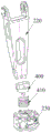
图4为本发明中电磁吸附式足端结构的示意图;Fig. 4 is the schematic diagram of electromagnetic adsorption type foot end structure in the present invention;
图5为本发明中电磁吸附式足端结构的分解结构示意图;5 is a schematic diagram of the decomposition structure of the electromagnetic adsorption type foot end structure in the present invention;
图6为本发明中座体的结构示意图;Fig. 6 is the structural schematic diagram of seat body in the present invention;
图7为本发明中开关固定座的示意图;Fig. 7 is a schematic diagram of a switch holder in the present invention;
图8为本发明中踝关节与足端连接的分解结构示意图。Fig. 8 is a schematic diagram of an exploded structure of the connection between the ankle joint and the foot end in the present invention.
图1-图8中,零部件的对应关系如下:In Figure 1-Figure 8, the corresponding relationship of parts is as follows:
机器人本体100,机械腿200,基体300,踝关节400;
大腿部210,小腿部220,足端230;
座体231,电磁铁232,微动开关233,浮动环234,紧固螺钉235,导向螺栓236,弹簧2361,限位螺钉237,开关固定座238;
筒体2311,环形凸缘2312,第一通孔2313,圆柱体2314;
第二通孔2341Second through
上壁2381,第一侧壁2382,第二侧壁2383,下壁2384,挡壁2385,开口槽2386;An
关节体401,万向关节402,销轴403,紧固螺栓404,销钉405;
插槽4011;
固定孔4021,螺帽4031,环形凹槽4032;Fixing
调整弹簧410。Adjust
具体实施方式Detailed ways
下面将结合本发明实施例附图,对本发明实施例的技术方案进行清楚、完整地描述,显然,以下所描述的实施例,仅仅是本发明的一部分实施例,而不是全部的实施例。基于本发明的实施例,本领域普通技术人员在没有做出创造性劳动的前提下,所获得的所有其他实施例,都属于本发明保护的范围。The following will clearly and completely describe the technical solutions of the embodiments of the present invention in conjunction with the accompanying drawings of the embodiments of the present invention. Obviously, the embodiments described below are only some of the embodiments of the present invention, not all of them. Based on the embodiments of the present invention, all other embodiments obtained by persons of ordinary skill in the art without creative efforts fall within the protection scope of the present invention.
本发明的实现原理是:Realization principle of the present invention is:
多足爬壁机器人的电磁吸附式足端结构中,电磁铁设置在座体内,三个微动开关沿座体的周向均布设置并固定在座体的外壁上,微动开关下方浮动设置一个浮动环,通过浮动环触发闭合微动开关实现断电,且只有当三个微动开关均触发时,才会切断电磁铁的供电,保证了电磁铁只有在与钢铁结构的表面完全紧密接触时,才会断电产生电磁吸力,确保吸附安全,避免了由于电磁铁与钢铁结构的表面接触面不严密,电磁吸力小,致使机器人脱落损坏的事故发生。In the electromagnetic adsorption type foot end structure of the multi-legged wall-climbing robot, the electromagnet is arranged in the base body, three micro switches are arranged evenly along the circumference of the base body and fixed on the outer wall of the base body, and a floating ring is floatingly arranged under the micro switch, The closed microswitches are triggered by the floating ring to realize power failure, and only when the three microswitches are triggered, the power supply of the electromagnet will be cut off, which ensures that the electromagnet will only be in close contact with the surface of the steel structure. The electromagnetic attraction is generated when the power is off, which ensures the safety of the adsorption and avoids the accident that the robot falls off and is damaged due to the loose contact surface between the electromagnet and the steel structure and the small electromagnetic attraction.
为了对本发明的技术方案和实现方式做出更清楚地解释和说明,以下介绍实现本发明技术方案的几个优选的具体实施例。In order to explain and describe the technical solution and implementation of the present invention more clearly, the following introduces several preferred specific embodiments for realizing the technical solution of the present invention.
需要说明的是,本文中“内、外”、“前、后”及“左、右”等方位词是以产品使用状态为基准对象进行的表述,显然,相应方位词的使用对本方案的保护范围并非构成限制。It should be noted that the orientation words such as "inside, outside", "front, back" and "left, right" in this article are expressed with the product use status as the reference object. Obviously, the use of the corresponding orientation words protects the protection of this scheme The scope is not intended to be limiting.
请参见图1,图1为本发明提供的一种多足爬壁机器人的示意图。Please refer to FIG. 1 , which is a schematic diagram of a multi-legged wall-climbing robot provided by the present invention.
如图1所示,本发明提供的一种多足爬壁机器人,包括机器人本体100和设置在机器人本体100上的多只机械腿200。机器人本体100内设有机器人控制系统,机械腿200具有由各舵机分别驱动的多个关节,通过机器人控制系统控制各舵机,使机械腿200产生相应的动作,完成行走功能。本实施例中,共设置6只机械腿,沿机器人本体100的周向均布设置。关于控制系统的硬件组成以及控制软件不是本发明的重点,可采用成熟的现有技术实现,在此不再赘述。As shown in FIG. 1 , a multi-legged wall-climbing robot provided by the present invention includes a
如图2、图3所示,机械腿200由大腿部210、小腿部220和足端230组成,大腿部210的上端通过髋关节240连接到基体300上,基体300固定在机器人本体100内。足端230通过踝关节400连接到小腿部220的下端,足端230与踝关节400之间设有调整弹簧410。足端230具有电磁吸附式足端结构。As shown in Figure 2 and Figure 3, the
如图4、图5所示,足端230的电磁吸附式足端结构包括座体231、电磁铁232、微动开关233和浮动环234。As shown in FIG. 4 and FIG. 5 , the electromagnetic adsorption foot end structure of the
再结合图6,座体231具有一个圆筒形的筒体2311,筒体2311的下端敞口,电磁铁232设置在筒体2311内,电磁铁232采用失电型电磁铁,通过紧固螺钉235固定在筒体2311的顶壁底面上。三个微动开关233沿筒体2311的周向均布设置并固定在筒体2311的外壁上,筒体2311的外壁上设有环形凸缘2312,环形凸缘2312上设有多个第一通孔2313,浮动环234上设有与第一通孔2313对应的第二通孔2341,浮动环234浮动设置在筒体2311的外圆周面上,且位于微动开关233的下方。根据全部的微动开关233的闭合切断电磁铁232的供电。6, the
具体地,浮动环234套设在筒体2311的外圆周面上,导向螺栓236的两端分别穿过第一通孔和第二通孔,且自由端安装限位螺钉237,导向螺栓236上套设有弹簧2361,导向螺栓236的直径小于第一通孔2313和第二通孔的2341直径,使浮动环234可沿导向螺栓236上下移动。Specifically, the floating
再参见图6,筒体2311的外圆周面上设有多个圆柱体2314,圆柱体2314竖直设置,第一通孔2313贯穿圆柱体2314的轴线设置,多个圆柱体2314沿筒体2311的周向均布设置,且通过环形凸缘2312连接。Referring to Fig. 6 again, a plurality of
相邻的两个圆柱体2314之间设有微动开关233的开关固定座238,如图7所示,开关固定座238包括上壁2381,上壁2381的两端分别垂直设置有第一侧壁2382和第二侧壁2383,其中,第二侧壁2383的长度大于第一侧壁2382,且下端朝向第一侧壁2382设有下壁2384,第一侧壁2382的下端设有与上壁平行设置在挡壁2385,挡壁2385的外端面与筒体2311的外圆周面相切。上壁2381上设有与微动开关233的接线端子相适配的开口槽2386。The
由于筒体2311的外圆周面为圆柱面,因此,微动开关233与筒体2311的外圆周面固定需要采用特殊的结构,即保证固定牢靠,又要安装方便。本发明提供的开关固定座238,上壁2381、第一侧壁2382、第二侧壁2383和下壁2384形成一个箱形容纳槽,微动开关233插入到该箱形容纳槽内,微动开关233的三个接续端子插入到开口槽2386内,后端面抵靠在挡壁2385上,安装非常方便,特别是,挡壁2385形成一个平面,微动开关233的后端面抵靠在挡壁2385上,微动开关233安装后非常稳固定,不会晃动,保证了微动开关233的工作可靠性。Since the outer peripheral surface of the
如图8所示,踝关节400包括关节体401、万向关节402和销轴403。其中,关节体401的上端设有插槽4011,万向关节402通过紧固螺栓404固定在插槽4011的底面上,小腿部220的下端插装在插槽4011内固定。销轴403的上部设有螺帽4031,螺帽4031的上部设有连接轴,连接轴上设有环形凹槽4032,万向关节402的下端关节壁上设有两个固定孔4021,销轴403的下部为螺纹部,通过螺纹部与电磁铁232固定,销轴403上端的连接轴插入到万向关节402的下端关节壁内,两个调整销钉405分别穿过固定孔4021,内端插入到环形凹槽4032内,将销轴403与万向关节402连接,销钉405的内端为锥台形,座体231与万向关节402的连接方便。As shown in FIG. 8 , the ankle joint 400 includes a
筒体2311的顶面上凸设设有用于安装调整弹簧410的环形槽,调整弹簧410的下端放置在环形槽内,上端与关节体401的底面相抵,通过扳手转动螺帽4031,可以调整关节体401与筒体2311之间的距离,进而改变调整弹簧410的压缩量,从而使足端230在任意角度时都具有更好的弹性。The top surface of the
为了确保爬壁机器人的足端与钢铁结构之间的磁吸力,当足端与钢铁结构的表面接触时,继续施加压力,使电磁铁232的底面与钢铁结构的表面产生一定的压力,该压力使得浮动环234向上移动,触碰微动开关233,从而切断电磁铁232的供电,产生吸力。In order to ensure the magnetic attraction between the foot end of the wall-climbing robot and the steel structure, when the foot end is in contact with the surface of the steel structure, continue to apply pressure, so that the bottom surface of the
本发明提供的方案中,只有当三个微动开关233均触发时,才会切断电磁铁232的供电,三个微动开关233均触发,表明电磁铁232的底面与钢铁结构的表面是平齐的,如果电磁铁232的底面与钢铁结构的表面倾斜,则至少有一个微动开关233不会触发,这样就保证了电磁铁232只有在与钢铁结构的表面完全垂直并紧密接触时,才会断电产生电磁吸力,确保吸附安全,避免了由于电磁铁与钢铁结构的表面接触面不严密,电磁吸力小,致使机器人脱落损坏的事故发生。In the solution provided by the present invention, only when the three
综合以上具体实施例的描述,本发明提供的可快速拆装的管道接头以及用于管道快速拆装的连接结构,与现有技术相比,具有如下优点:Based on the descriptions of the specific embodiments above, the quick-disassembly pipeline joint and the connection structure for pipeline quick-disassembly provided by the present invention have the following advantages compared with the prior art:
第一,多足爬壁机器人的电磁吸附式足端结构中,电磁铁通过三个微动开关实现断电,工作可靠。First, in the electromagnetic adsorption foot end structure of the multi-legged wall-climbing robot, the electromagnet is powered off through three micro switches, and the work is reliable.
第二,只有当三个微动开关均触发时,才会切断电磁铁的供电,保证了电磁铁只有在与钢铁结构的表面完全紧密接触时,才会断电产生电磁吸力,确保吸附安全,避免了由于电磁铁与钢铁结构的表面接触面不严密,电磁吸力小,致使机器人脱落损坏的事故发生。Second, only when the three micro switches are triggered, the power supply of the electromagnet will be cut off, which ensures that the electromagnet will only cut off the power to generate electromagnetic attraction when it is in complete and close contact with the surface of the steel structure, ensuring the safety of the adsorption. It avoids accidents that the robot falls off and is damaged because the contact surface between the electromagnet and the steel structure is not tight and the electromagnetic attraction force is small.
第三,微动开关的开关固定座采用特殊的结构,即保证固定牢靠,又要安装方便。Third, the switch fixing seat of the micro switch adopts a special structure, which not only ensures firm fixing, but also facilitates installation.
第四、踝关节包括关节体、万向关节和销轴,销轴的上部设有连接轴,连接轴上设有环形凹槽,销轴上端的连接轴插入到万向关节的下端关节壁内,两个调整销钉分别穿过万向关节的下端关节壁上的固定孔,内端插入到环形凹槽内,将销轴与万向关节连接,销钉的内端为锥台形,底座与万向关节连接方便,并可进行周向微调整,以保证初始状态下三个微动开关能够正常工作。Fourth, the ankle joint includes a joint body, a universal joint and a pin shaft. The upper part of the pin shaft is provided with a connecting shaft, and an annular groove is provided on the connecting shaft. The connecting shaft at the upper end of the pin shaft is inserted into the joint wall at the lower end of the universal joint , the two adjustment pins respectively pass through the fixing holes on the joint wall at the lower end of the universal joint, and the inner ends are inserted into the annular groove to connect the pin shaft with the universal joint. The joints are conveniently connected and can be finely adjusted in the circumferential direction to ensure that the three micro switches can work normally in the initial state.
最后,还需要说明的是,在本文中使用的术语"包括"、"包含"或者其任何其他变体意在涵盖非排他性的包含,从而使得包括一系列要素的过程、方法、物品或者设备不仅包括那些要素,而且还包括没有明确列出的其他要素,或者是还包括为这种过程、方法、物品或者设备所固有的要素。在没有更多限制的情况下,由语句"包括一个…"限定的要素,并不排除在包括所述要素的过程、方法、物品或者设备中还存在另外的相同要素。Finally, it should also be noted that the terms "comprises", "comprises" or any other variation thereof as used herein are intended to cover a non-exclusive inclusion such that a process, method, article or apparatus comprising a series of elements not only includes those elements, but also includes other elements not expressly listed, or which are inherent in the process, method, article, or apparatus. Without further limitations, an element defined by the phrase "comprising a..." does not exclude the presence of additional identical elements in the process, method, article or apparatus comprising said element.
本发明并不局限于上述最佳实施方式,任何人应该得知在本发明的启示下做出的结构变化,凡是与本发明具有相同或相近的技术方案,均落入本发明的保护范围之内。The present invention is not limited to the above-mentioned best implementation mode, and anyone should know that the structural changes made under the inspiration of the present invention, all technical solutions that are identical or similar to the present invention, all fall within the scope of protection of the present invention Inside.
Claims (9)
Priority Applications (1)
| Application Number | Priority Date | Filing Date | Title |
|---|---|---|---|
| CN202210007717.3A CN114313047B (en) | 2022-01-06 | 2022-01-06 | Multi-foot wall-climbing robot and electromagnetic adsorption type foot end structure thereof |
Applications Claiming Priority (1)
| Application Number | Priority Date | Filing Date | Title |
|---|---|---|---|
| CN202210007717.3A CN114313047B (en) | 2022-01-06 | 2022-01-06 | Multi-foot wall-climbing robot and electromagnetic adsorption type foot end structure thereof |
Publications (2)
| Publication Number | Publication Date |
|---|---|
| CN114313047A CN114313047A (en) | 2022-04-12 |
| CN114313047B true CN114313047B (en) | 2023-04-07 |
Family
ID=81025656
Family Applications (1)
| Application Number | Title | Priority Date | Filing Date |
|---|---|---|---|
| CN202210007717.3A Expired - Fee Related CN114313047B (en) | 2022-01-06 | 2022-01-06 | Multi-foot wall-climbing robot and electromagnetic adsorption type foot end structure thereof |
Country Status (1)
| Country | Link |
|---|---|
| CN (1) | CN114313047B (en) |
Family Cites Families (7)
| Publication number | Priority date | Publication date | Assignee | Title |
|---|---|---|---|---|
| JPH06114758A (en) * | 1992-10-02 | 1994-04-26 | Mitsubishi Heavy Ind Ltd | Three-dimensionally moving robot for beam structure |
| CN103264734B (en) * | 2013-04-22 | 2015-06-17 | 浙江大学 | Sole ground touch sensing mechanism of legged robot |
| CH711196A2 (en) * | 2015-06-05 | 2016-12-15 | Logistics Wash Holding Ag | Chassis with linear and pivoting movements with detachable feet detachable with respect to the travel surface. |
| CN106184452A (en) * | 2016-08-10 | 2016-12-07 | 西安交通大学 | A kind of all fours type electromagnetic adsorption climbing robot |
| CN206443649U (en) * | 2016-11-18 | 2017-08-29 | 深圳市普森斯科技有限公司 | A kind of window wiping robot of magnetic-adsorption structure |
| CN110920767A (en) * | 2019-10-31 | 2020-03-27 | 武汉理工大学 | Electromagnetic adsorption six-foot climbing robot |
| CN111003072A (en) * | 2019-12-11 | 2020-04-14 | 深圳怪虫机器人有限公司 | Induction sole of cleaning robot |
-
2022
- 2022-01-06 CN CN202210007717.3A patent/CN114313047B/en not_active Expired - Fee Related
Also Published As
| Publication number | Publication date |
|---|---|
| CN114313047A (en) | 2022-04-12 |
Similar Documents
| Publication | Publication Date | Title |
|---|---|---|
| EP2973878B1 (en) | Waterproof separable swivel connector | |
| CN205059785U (en) | Polypody robot platform of imitative insect | |
| CN105864570B (en) | A kind of adaptive caliber can turn multi-functional formula petroleum pipeline robot | |
| CN114313047B (en) | Multi-foot wall-climbing robot and electromagnetic adsorption type foot end structure thereof | |
| CN102897303B (en) | Underwater electromechanical removal device | |
| CN109436121B (en) | A surface-adaptive omnidirectional wall-climbing robot based on slip drive | |
| CN105460100B (en) | A kind of climbing robot Acetabula device for being adapted to complex surface | |
| CN102897302B (en) | Underwater mechanical separating mechanism | |
| CN209839486U (en) | Peristaltic pipeline robot | |
| CN105171776B (en) | A kind of detectable foot contacts the multi-foot robot flexible foot system of situation with ground | |
| CN105774941A (en) | Hexapod universal walking robot | |
| CN113562091B (en) | Flexible electrostatic chuck | |
| CN113428255B (en) | A modular multi-wheeled legged robot | |
| CN113335409B (en) | Wall-climbing robot based on roller type sucker | |
| ES2116534T3 (en) | SELF-POWERED APPARATUS FOR THE TREATMENT OF FLUIDS USING EXTERNAL ELECTRODES. | |
| CN209441469U (en) | A kind of comprehensive climbing robot of curved surface adaptive based on sliding driving | |
| CN119099248B (en) | Wheel assembly and robot having it | |
| CN204997692U (en) | Underwater mating device positioning mechanism | |
| CN209087645U (en) | An underwater trigger button | |
| CN217097841U (en) | Joint casing, joint assembly and robot | |
| CN111347456B (en) | Seven-axis cooperative robot | |
| CN113942033B (en) | Joint housing, joint assembly and robot | |
| CN108407918B (en) | A gas balancing robot | |
| CN201154482Y (en) | Ball joint electric locking device | |
| CN216508686U (en) | Electromagnetic adsorption foot of wall-climbing robot |
Legal Events
| Date | Code | Title | Description |
|---|---|---|---|
| PB01 | Publication | ||
| PB01 | Publication | ||
| SE01 | Entry into force of request for substantive examination | ||
| SE01 | Entry into force of request for substantive examination | ||
| GR01 | Patent grant | ||
| GR01 | Patent grant | ||
| CF01 | Termination of patent right due to non-payment of annual fee |
Granted publication date: 20230407 |
|
| CF01 | Termination of patent right due to non-payment of annual fee |