CN114295118A - Multi-robot positioning method, device and equipment - Google Patents
Multi-robot positioning method, device and equipment Download PDFInfo
- Publication number
- CN114295118A CN114295118A CN202111656442.8A CN202111656442A CN114295118A CN 114295118 A CN114295118 A CN 114295118A CN 202111656442 A CN202111656442 A CN 202111656442A CN 114295118 A CN114295118 A CN 114295118A
- Authority
- CN
- China
- Prior art keywords
- robot
- pose
- target
- navigation
- positioning
- Prior art date
- Legal status (The legal status is an assumption and is not a legal conclusion. Google has not performed a legal analysis and makes no representation as to the accuracy of the status listed.)
- Granted
Links
- 238000000034 method Methods 0.000 title claims abstract description 49
- 239000003550 marker Substances 0.000 claims description 39
- 238000004422 calculation algorithm Methods 0.000 claims description 29
- 238000001914 filtration Methods 0.000 claims description 8
- 238000010586 diagram Methods 0.000 description 14
- 230000006870 function Effects 0.000 description 12
- 230000008569 process Effects 0.000 description 10
- 230000000007 visual effect Effects 0.000 description 9
- 230000015572 biosynthetic process Effects 0.000 description 8
- 238000004590 computer program Methods 0.000 description 7
- 238000011156 evaluation Methods 0.000 description 5
- 238000004519 manufacturing process Methods 0.000 description 5
- 238000013441 quality evaluation Methods 0.000 description 5
- 238000004364 calculation method Methods 0.000 description 4
- 230000003287 optical effect Effects 0.000 description 4
- 238000012545 processing Methods 0.000 description 4
- 108091034117 Oligonucleotide Proteins 0.000 description 2
- 230000008859 change Effects 0.000 description 2
- 238000001514 detection method Methods 0.000 description 2
- 238000011161 development Methods 0.000 description 2
- 238000005516 engineering process Methods 0.000 description 2
- 230000004048 modification Effects 0.000 description 2
- 238000012986 modification Methods 0.000 description 2
- 238000013473 artificial intelligence Methods 0.000 description 1
- 230000001413 cellular effect Effects 0.000 description 1
- 230000004069 differentiation Effects 0.000 description 1
- 230000000694 effects Effects 0.000 description 1
- 230000007613 environmental effect Effects 0.000 description 1
- 230000006872 improvement Effects 0.000 description 1
- 230000004807 localization Effects 0.000 description 1
- 238000013507 mapping Methods 0.000 description 1
- 230000004044 response Effects 0.000 description 1
- 239000007787 solid Substances 0.000 description 1
Images


Landscapes
- Control Of Position, Course, Altitude, Or Attitude Of Moving Bodies (AREA)
Abstract
The application provides a method, a device and equipment for positioning multiple robots, wherein the method comprises the following steps: acquiring a navigation positioning pose of a target robot under a target coordinate system, wherein the navigation positioning pose is a pose when the target robot positions the target robot through data acquired by a sensor; determining an object pose of a target object in the target coordinate system based on the navigation positioning pose; and determining an estimated pose of the cooperative robot under the target coordinate system based on the object pose. By the technical scheme, cooperative control of multiple robots is achieved, the whole cooperative navigation precision is improved, and the consistency and precision of navigation positioning are obviously improved.
Description
Technical Field
The application relates to the technical field of robot control, in particular to a method, a device and equipment for positioning multiple robots.
Background
In recent years, various types of mobile robots have been rapidly developed in the technical and market fields, and mobile robots are machine devices that automatically perform work and are machines that implement various functions by means of their own power and control capabilities. The mobile robot can receive human commands, run pre-programmed programs and act according to strategies formulated by artificial intelligence. For example, a user uses a manual remote controller to control the mobile robot to perform a related operation, for example, the manual remote controller issues an operation command to the mobile robot in a wireless manner, and after receiving the operation command, the mobile robot performs an operation specified by the operation command to complete a related function.
With the rapid development of mobile robot technology, the mobile robot is more and more widely applied to logistics, warehousing, factory production and the like, such as the use of the mobile robot to transport objects. According to different application scenarios, mobile robots with different load capacities can be designed, such as mobile robots for heavy-weight transportation tasks and mobile robots for ordinary-weight transportation tasks. In practical application scenarios, most of the transportation tasks may be ordinary weight transportation tasks, and occasionally heavy transportation tasks exist, that is, the use efficiency of the mobile robot for the heavy transportation tasks is very low, and the mobile robot for the heavy transportation tasks is not needed.
For this reason, when a heavy object needs to be carried, a plurality of mobile robots are generally required to complete the transportation task of the heavy object in a cooperative transportation manner. However, there is currently no reasonable implementation for accomplishing the transportation task of a heavy object in a coordinated transportation manner using a plurality of mobile robots.
Disclosure of Invention
The application provides a multi-robot positioning method, when at least two robots transport the same target object together, one robot of the at least two robots is selected as a target robot, and the rest robots except the target robot are cooperative robots, the method comprises the following steps:
acquiring a navigation positioning pose of the target robot under a target coordinate system; the navigation positioning pose is the pose when the target robot positions the target robot through data acquired by a sensor;
determining an object pose of the target object in the target coordinate system based on the navigation positioning pose;
determining an estimated pose of the collaborative robot in the target coordinate system based on the object pose.
The application provides a positioner of multirobot, when two at least robots transport same target object jointly, one robot in two at least robots is chosen as the target robot, remaining robot outside the target robot is cooperative robot, the device includes:
the system comprises an acquisition module, a navigation positioning module and a navigation positioning module, wherein the acquisition module is used for acquiring a navigation positioning pose of a target robot under a target coordinate system, and the navigation positioning pose is a pose of the target robot when the target robot positions the target robot through data acquired by a sensor;
the determining module is used for determining the object pose of the target object in the target coordinate system based on the navigation positioning pose; determining an estimated pose of the collaborative robot in a target coordinate system based on the object pose.
The application provides a multi-robot positioning device, which comprises a processor and a machine-readable storage medium, wherein the machine-readable storage medium stores machine-executable instructions capable of being executed by the processor; the processor is used for executing machine executable instructions to realize the positioning method of the multiple robots.
According to the technical scheme, in the embodiment of the application, the object pose of the target object in the target coordinate system is determined based on the navigation and positioning pose of the target robot in the target coordinate system, the estimation pose of the cooperative robot in the target coordinate system is determined based on the object pose of the target object in the target coordinate system, and the target robot and the cooperative robot are cooperatively controlled in the transportation process of the target object based on the navigation and positioning pose and the estimation pose, so that the cooperative control of multiple robots is realized. The robot with the highest navigation and positioning quality can be used as a target robot, the navigation and positioning pose based on the target robot is used as the positioning reference of the whole formation, the navigation and positioning of the cooperative robot with low positioning precision are related to the positioning of the target robot with the highest positioning quality, the whole cooperative navigation precision is improved, the whole environment adaptability and consistency of cooperative navigation are improved, the consistency and precision of the navigation and positioning are obviously improved, and the cooperative navigation and positioning of multiple robots are realized.
Drawings
In order to more clearly illustrate the embodiments of the present application or the technical solutions in the prior art, the drawings needed to be used in the description of the embodiments of the present application or the prior art will be briefly described below, it is obvious that the drawings in the following description are only some embodiments described in the present application, and other drawings can be obtained by those skilled in the art according to the drawings of the embodiments of the present application.
FIG. 1 is a schematic flow chart diagram illustrating a multi-robot positioning method according to an embodiment of the present disclosure;
FIG. 2 is a diagram illustrating multi-machine collaborative navigation in one embodiment of the present application;
FIG. 3 is a flow chart illustrating a method for positioning multiple robots in accordance with an embodiment of the present disclosure;
FIG. 4 is a schematic diagram of a multi-robot positioning device according to one embodiment of the present application;
fig. 5 is a hardware block diagram of a multi-robot pointing device according to an embodiment of the present application.
Detailed Description
The terminology used in the embodiments of the present application is for the purpose of describing particular embodiments only and is not intended to be limiting of the application. As used in this application and the claims, the singular forms "a", "an", and "the" are intended to include the plural forms as well, unless the context clearly indicates otherwise. It should also be understood that the term "and/or" as used herein is meant to encompass any and all possible combinations of one or more of the associated listed items.
It should be understood that although the terms first, second, third, etc. may be used in the embodiments of the present application to describe various information, the information should not be limited to these terms. These terms are only used to distinguish one type of information from another. For example, first information may also be referred to as second information, and similarly, second information may also be referred to as first information, without departing from the scope of the present application. Depending on the context, moreover, the word "if" as used may be interpreted as "at … …" or "when … …" or "in response to a determination".
The embodiment of the application provides a method for positioning multiple robots, and the same target object can be transported by at least two robots together. When at least two robots transport the same target object together, one of the at least two robots is selected as a target robot and the remaining robots other than the target robot are cooperative robots, as shown in fig. 1, which is a flowchart of a positioning method of multiple robots, the method comprising:
For example, before step 101, one robot may be selected as the target robot from at least two robots, for example, the target robot may be selected as follows: and acquiring navigation quality data corresponding to each robot, wherein the navigation quality data are used for reflecting the accuracy of the navigation positioning pose obtained when the robot positions the robot through the data acquired by the sensor. And selecting the robot with the best navigation and positioning quality from the at least two robots based on the navigation quality data corresponding to each robot, and determining the robot with the best navigation and positioning quality as a target robot, wherein the target robot is the robot with the best navigation and positioning quality.
For example, the robot with the best navigation positioning quality is selected from at least two robots based on the navigation quality data corresponding to each robot, which may include but is not limited to the following ways: when the robot positions the robot through data acquired by a radar sensor, the navigation quality data comprises a first matching degree of a laser point outline and a map outline; on the basis, the robot with the maximum first matching degree can be selected as the robot with the best navigation and positioning quality based on the first matching degree corresponding to each robot. And/or when the robot positions itself through the data acquired by the vision sensor, the navigation quality data comprises a second matching degree of the image characteristic points and the map characteristic points; on the basis, the robot with the maximum second matching degree can be selected as the robot with the best navigation and positioning quality based on the second matching degree corresponding to each robot. And/or when the robot positions the robot through the Kalman filtering integrated navigation algorithm, the navigation quality data comprise covariance, and the covariance represents the credibility of the navigation positioning result; on the basis, the robot corresponding to the minimum covariance can be selected as the robot with the best navigation positioning quality based on the covariance corresponding to each robot. And/or when the robot positions the robot through two-dimensional code navigation, the navigation quality data comprises a target distance between a two-dimensional code center and an image center; on the basis, the robot with the minimum target distance can be selected as the robot with the best navigation positioning quality based on the target distance corresponding to each robot.
And 102, determining the object pose of the target object in the target coordinate system based on the navigation positioning pose.
In one possible embodiment, determining the object pose of the target object in the target coordinate system based on the navigation positioning pose may include, but is not limited to: determining a first target pose (when the position identifier is a cargo code, the target pose can be also called a cargo code pose) under a target coordinate system based on the navigation positioning pose and the first relative pose (the position identifier can be a cargo code or other types of identifiers without limitation); wherein the target object may comprise a first position marker, and the first position marker is detectable by the target robot, the first relative pose being the pose of the first position marker in the coordinate system of the target robot. And determining the object pose of the target object in the target coordinate system based on the first target pose and the configured pose of the first position identifier in the coordinate system of the target object.
For example, before determining the first target pose of the first position marker in the target coordinate system based on the navigation positioning pose and the first relative pose, the first position marker may be scanned by the target robot to obtain the first relative pose between the first position marker and the target robot.
And 103, determining the estimated pose of the cooperative robot in the target coordinate system based on the object pose.
In one possible embodiment, determining the estimated pose of the cooperative robot in the target coordinate system based on the object pose may include, but is not limited to: a second target pose of the second position marker in the target coordinate system may be determined based on the object pose and the configured pose of the second position marker in the coordinate system of the target object; wherein the target object may include the second position identifier, and the second position identifier may be detectable by the cooperative robot. And determining an estimated pose of the cooperative robot in the target coordinate system based on the second target pose and a second relative pose of the second position identifier in the coordinate system of the cooperative robot.
For example, before determining the estimated pose of the cooperative robot in the target coordinate system based on the second target pose and the second relative pose of the second position identifier in the coordinate system of the cooperative robot, the second relative pose may be obtained first, for example, the second position identifier may be scanned by the cooperative robot to obtain the second relative pose between the second position identifier and the cooperative robot.
Illustratively, when at least two robots transport the same target object together, step 101 and step 103 may be performed periodically, and in each period, the robot with the best navigation positioning quality may be determined again, and the robot with the best navigation positioning quality is used as the target robot. At each cycle, the first position marker is scanned by the target robot to obtain a first relative pose between the first position marker and the target robot, and then the object pose of the target object in the target coordinate system is determined based on the first relative pose. And scanning the second position identifier through the cooperative robot in each period to obtain a second relative pose between the second position identifier and the cooperative robot, and then determining the estimated pose of the cooperative robot in the target coordinate system based on the second relative pose.
For example, after the navigation positioning pose of the target robot and the estimated pose of the cooperative robot are obtained, the transportation process of the target robot and the cooperative robot for the target object can be cooperatively controlled based on the navigation positioning pose of the target robot and the estimated pose of the cooperative robot.
In the above embodiment, the target coordinate system may be a world coordinate system, and the type of the target coordinate system is not limited, and the following description will be given by taking the world coordinate system as an example.
According to the technical scheme, in the embodiment of the application, the object pose of the target object in the target coordinate system is determined based on the navigation and positioning pose of the target robot in the target coordinate system, the estimation pose of the cooperative robot in the target coordinate system is determined based on the object pose of the target object in the target coordinate system, and the target robot and the cooperative robot are cooperatively controlled in the transportation process of the target object based on the navigation and positioning pose and the estimation pose, so that the cooperative control of multiple robots is realized. The robot with the highest navigation and positioning quality can be used as a target robot, the navigation and positioning pose based on the target robot is used as the positioning reference of the whole formation, the navigation and positioning of the cooperative robot with low positioning precision are related to the positioning of the target robot with the highest positioning quality, the whole cooperative navigation precision is improved, the whole environment adaptability and consistency of cooperative navigation are improved, the consistency and precision of the navigation and positioning are obviously improved, and the cooperative navigation and positioning of multiple robots are realized.
The following describes the technical solution of the embodiment of the present application with reference to a specific application scenario.
The mobile robot is a machine device that automatically executes work, and is a machine that realizes various functions depending on its own power and control capability, and the type of the mobile robot is not limited, and may be any type of mobile robot as long as the mobile robot has a transportation function, such as an AGV (automated Guided Vehicle). An AGV is a transport vehicle having an electromagnetic or optical automatic guide device, which can travel along a predetermined guide path, and has safety protection, movement, and loading functions.
With the rapid development of mobile robot technology, the mobile robot is more and more widely applied to logistics, warehousing, factory production and the like, such as the use of the mobile robot to transport objects. According to different application scenarios, mobile robots with different load capacities can be designed, such as a mobile robot for heavy-weight transportation tasks (e.g., a warehousing robot) and a mobile robot for ordinary-weight transportation tasks (e.g., a logistics sorting robot).
In practical application scenarios, most of the transportation tasks may be ordinary weight transportation tasks, and occasionally heavy transportation tasks exist, that is, the mobile robot for the heavy transportation tasks is inefficient to use, and the mobile robot for the heavy transportation tasks does not need to be used. When a heavy object needs to be transported, a plurality of mobile robots are usually required to complete the transportation task of the heavy object in a cooperative transportation mode, obviously, most of the time of each mobile robot is the transportation task of the common heavy object, and when the heavy object needs to be transported, the plurality of mobile robots perform cooperative transportation, so that the production cost is reduced, and the production efficiency is improved.
In summary, cooperative transportation of multiple mobile robots (i.e. multi-robot cooperative transportation, also called multi-robot cooperative control) is a basic function of the mobile robots, and multi-robot cooperative navigation is a basis for multi-robot cooperative control. Wherein, the multi-machine cooperative control means that: in order to complete a certain task, a plurality of mobile robots are cooperatively controlled to complete the task which cannot be completed by a single mobile robot or achieve a better task completion effect. The multi-machine collaborative navigation means: and (3) providing collaborative group navigation data with higher reliability by combining sensor data or navigation positioning data of a plurality of mobile robots, wherein the multi-robot collaborative navigation is a main component of multi-robot collaborative control.
In the multi-machine collaborative navigation process, aiming at each mobile robot, the mobile robot positions itself through data acquired by a sensor thereof to obtain a navigation positioning pose of the mobile robot, so that the following problems exist: the navigation accuracy of some mobile robots is not high, while the navigation accuracy of other mobile robots is high. Navigation positioning inconsistency among the mobile robots is caused by positioning accuracy inconsistency.
Referring to fig. 2, which is a schematic diagram of multi-robot cooperative navigation, when mobile robot a and mobile robot B perform cooperative transportation, the detection range of mobile robot B may be affected by mobile robot a, for example, a semicircle is shown in fig. 2 as an example of the detection range. Obviously, mobile robot B has higher navigation accuracy than mobile robot a, and mobile robot B has lower navigation accuracy than mobile robot a.
In addition, assuming that the positioning accuracy of mobile robot a is on the order of 1cm and the positioning accuracy of mobile robot B is on the order of 10cm, navigation positioning may be inconsistent when mobile robot a and mobile robot B perform positioning using the respective positioning accuracies. For example, if the actual distance between mobile robot a and mobile robot B is 3m, the desired formation is also 3m, the navigation position of mobile robot a is (3.02, 0), and the navigation position of mobile robot B is (0, 0), it is considered that a formation control deviation of 2cm occurs, and the control amount for reducing the control deviation occurs, which affects the formation control accuracy. However, the reason why the above-described formation control deviation occurs is that the positioning accuracy of mobile robot a is on the order of 1cm and the positioning accuracy of mobile robot B is on the order of 10cm, that is, mobile robot B does not output (0.02, 0) navigation positioning.
In order to solve the above problems, the embodiment of the present application provides a multi-robot collaborative navigation positioning method, which can use the navigation positioning pose of the target robot with the highest navigation positioning quality as the positioning reference of the whole formation, and associate the navigation positioning of the collaborative robot with low positioning accuracy to the target robot with the highest positioning quality, so as to improve the whole collaborative navigation accuracy, improve the overall environmental adaptability and consistency of collaborative navigation, obviously improve the consistency and accuracy of navigation positioning, and implement the collaborative navigation positioning of multiple robots.
In this embodiment, the same target object may be transported by at least two mobile robots (for convenience of description, in this embodiment, simply referred to as robots, such as AGVs, etc.), for example, the same target object may be transported by two robots, the same target object may be transported by three robots, or the same target object may be transported by four robots, which is not limited in this respect. For convenience of description, two robots are denoted as a robot a and a robot B by taking an example in which the same target object is transported by the two robots together.
When at least two robots transport the same target object together, the target object may include at least two position identifiers (e.g., goods codes, etc.), if the target object is attached with at least two position identifiers, each robot corresponds to one position identifier, e.g., the upper side of robot a corresponds to position identifier a, and robot a can scan position identifier a, the position relationship of position identifier a is not limited to the upper side of robot a, as long as robot a can scan position identifier a, the upper side of robot B corresponds to position identifier B, and robot B can scan position identifier B, the position relationship of position identifier B is not limited to the upper side of robot B, and robot B can scan position identifier B. For each position identifier, the position identifier may be a cargo code, such as a two-dimensional code, a barcode, or other types of cargo codes, and the type of the position identifier is not limited.
In the foregoing application scenario, an embodiment of the present application provides a method for positioning multiple robots, which is shown in fig. 3 and is a schematic flow chart of the method for positioning multiple robots, and the method may include:
301, acquiring the navigation positioning pose of each robot in a world coordinate system, and acquiring navigation quality data corresponding to each robot. Illustratively, the navigation positioning pose is a pose when the robot positions itself through data collected by the sensor, and the navigation quality data is used for reflecting the accuracy of the navigation positioning pose obtained when the robot positions itself through the data collected by the sensor.
For example, one robot may be selected from all robots as a management entity, or a central control device may be additionally deployed as a management entity. For each robot, the robot can acquire the navigation and positioning pose of the robot in a world coordinate system, acquire navigation quality data corresponding to the robot, and send the navigation and positioning pose and the navigation quality data to a management entity, that is, the management entity can acquire the navigation and positioning pose of each robot in the world coordinate system and acquire the navigation quality data corresponding to each robot. Obviously, in this embodiment, the management entity executes step 301 and the subsequent steps to realize the multi-robot positioning method, that is, the execution main body of the multi-robot positioning method is the management entity.
In a possible implementation manner, for each robot, the robot can position itself through data collected by the radar sensor to obtain a navigation positioning pose of the robot in a world coordinate system. For example, the robot may position itself by using a laser SLAM (Simultaneous Localization And Mapping) algorithm to obtain a navigation positioning pose, the laser SLAM algorithm may detect a surrounding environment by a radar sensor (such as a laser radar), And further obtain the navigation positioning pose of the robot by matching with a map, And the implementation process of the laser SLAM algorithm is not limited.
For example, when the robot locates itself by data collected by the radar sensor, then the navigation quality data may include a first degree of matching of the laser point profile to the map profile. For example, the laser SLAM algorithm scans and matches the laser point profile and the map profile to obtain the navigation and positioning pose of the robot in the map, so that the first matching degree of the laser point profile and the map profile can be used as a quality evaluation parameter of navigation and positioning, that is, the navigation quality data can include the first matching degree.
The first matching degree of the laser point profile and the map profile may be a ratio of the number of laser points located in the map profile to the total number of laser points, and a determination manner of the first matching degree is not limited.
For example, if the first matching degree of the laser point profile and the map profile is good, if most of the laser points fall within the map profile, it indicates that the accuracy of the navigation positioning pose is high when the navigation positioning pose is obtained by the laser SLAM algorithm, and if the first matching degree of the laser point profile and the map profile is poor (i.e., the deviation between the laser point profile and the map profile is large), if most of the laser points fall outside the map profile, it indicates that the accuracy of the navigation positioning pose is low when the navigation positioning pose is obtained by the laser SLAM algorithm, i.e., the navigation positioning pose is wrong. Based on the method, the first matching degree of the laser point outline and the map outline can be used as an evaluation standard for the positioning quality, and the larger the first matching degree is, the better the positioning quality is.
In another possible implementation manner, for each robot, the robot can be positioned through data acquired by a vision sensor, and a navigation positioning pose of the robot in a world coordinate system is obtained. For example, the robot uses the visual SLAM algorithm to position itself to obtain the navigation positioning pose, the visual SLAM algorithm may detect the surrounding environment through a visual sensor (such as a camera), and further obtain the navigation positioning pose of the robot through matching with a map, and the implementation process of the visual SLAM algorithm is not limited.
For example, when the robot locates itself through data collected by the vision sensor, then the navigation quality data may include a second degree of matching of image feature points with map feature points. For example, the visual SLAM algorithm obtains the navigation and positioning pose of the robot in the map through the matching relationship between the image feature points and the map feature points, so that the second matching degree between the image feature points and the map feature points can be used as a quality evaluation parameter of navigation and positioning, that is, the navigation quality data can include the second matching degree.
The second matching degree between the image feature points and the map feature points may be a ratio of the number of the image feature points to the number of the map feature points, and the determination manner of the second matching degree is not limited.
For example, if the second matching degree between the image feature point and the map feature point is good, it indicates that the accuracy of the navigation and positioning pose is high when the navigation and positioning pose is obtained by the visual SLAM algorithm, and if the second matching degree between the image feature point and the map feature point is poor, it indicates that the accuracy of the navigation and positioning pose is low when the navigation and positioning pose is obtained by the visual SLAM algorithm, that is, the navigation and positioning pose is wrong.
Based on this, the second matching degree of the image feature points and the map feature points can be used as an evaluation criterion of the positioning quality, that is, the larger the second matching degree is, the better the positioning quality is.
In another possible implementation manner, for each robot, the robot can position itself through a kalman filtering combined navigation algorithm to obtain a navigation positioning pose of the robot in a world coordinate system. The Kalman filtering combined navigation algorithm is a combined navigation algorithm based on probability statistics, and can fuse navigation results of various sensors (such as a radar sensor, a vision sensor and the like) and output the most possible navigation positioning result of the robot. For example, the robot can adopt a laser SLAM algorithm to position itself to obtain a navigation positioning pose 1, and can adopt a visual SLAM algorithm to position itself to obtain a navigation positioning pose 2, and then can adopt a Kalman filtering combined navigation algorithm to fuse the navigation positioning pose 1 and the navigation positioning pose 2 to obtain a navigation positioning pose of the robot in a world coordinate system.
Illustratively, the kalman filtering integrated navigation algorithm contains a data item of navigation positioning quality, namely covariance, and the meaning represented by the covariance is the credibility of the positioning result, and can be used as the evaluation standard of the navigation positioning quality, and the smaller the covariance is, the better the positioning quality is. Based on this, when the robot positions itself through the kalman filter integrated navigation algorithm, the navigation quality data may include the covariance in the kalman filter integrated navigation algorithm, that is, the covariance is used as the quality evaluation parameter of the navigation positioning.
In another possible implementation manner, for each robot, the robot can be positioned through two-dimensional code navigation, and a navigation positioning pose of the robot in a world coordinate system is obtained. For example, the robot acquires an image of the surrounding environment through a visual sensor (such as a camera), and obtains a navigation and positioning pose of the robot based on a target distance between the center of the two-dimensional code and the center of the image, without limitation to the two-dimensional code navigation process.
For example, when the robot positions itself through two-dimensional code navigation, the navigation quality data may include a target distance between the center of the two-dimensional code and the center of the image. For example, the two-dimensional code navigation algorithm acquires the navigation and positioning pose of the robot through the target distance between the center of the two-dimensional code and the center of the image, so the target distance between the center of the two-dimensional code and the center of the image can be used as a quality evaluation parameter for navigation and positioning, that is, the navigation quality data can include the target distance between the center of the two-dimensional code and the center of the image.
For example, if the target distance between the two-dimensional code center and the image center is small, it indicates that the accuracy of the navigation positioning pose is high when the navigation positioning pose is obtained by the two-dimensional code navigation algorithm, and if the target distance between the two-dimensional code center and the image center is large, it indicates that the accuracy of the navigation positioning pose is low when the navigation positioning pose is obtained by the two-dimensional code navigation algorithm, that is, the navigation positioning pose is wrong.
Based on this, the target distance between the center of the two-dimensional code and the center of the image can be used as an evaluation criterion for the quality of the positioning, that is, the smaller the target distance is, the better the positioning quality is.
In summary, for each robot, the robot may obtain a navigation positioning pose of the robot in a world coordinate system, and obtain navigation quality data corresponding to the robot, in the above embodiment, four obtaining manners are shown, and this embodiment does not limit this obtaining manner. After the navigation positioning pose and the navigation quality data are obtained, the robot can send the navigation positioning pose and the navigation quality data to the management entity, and the management entity can obtain the navigation positioning pose and the navigation quality data of each robot.
Wherein, the navigation positioning pose of each robot in the world coordinate system can be recorded as The navigation quality data corresponding to each robot can be recorded as
 i denotes a reference numeral of the robot,
 representing the navigation positioning pose corresponding to the robot i,
 and indicating the navigation quality data corresponding to the robot i.
 Indicates the position corresponding to the robot i,
 the gesture (such as the orientation angle) corresponding to the robot i is represented, and the position corresponding to the robot i and the gesture corresponding to the robot i form the navigation positioning pose corresponding to the robot i
For example, when the same target object is jointly transported by the robot a and the robot B, the navigation positioning pose of the robot a in the world coordinate system can be acquired And navigation quality data corresponding to the robot A is obtained
 Navigation positioning pose of the robot B under a world coordinate system can be obtained
 And acquiring navigation quality data corresponding to the robot B
For example, after the navigation quality data corresponding to each robot is obtained, the robot with the best navigation positioning quality can be selected from all robots. The navigation quality data is an evaluation of the quality (or the accuracy) of the robot navigation positioning result, and different quality evaluation criteria can be set according to different navigation quality data, as described in the following. For example, when the robot locates itself through data collected by the radar sensor to obtain the navigation positioning pose, the navigation quality data includes a first matching degree of the laser point profile and the map profile, and on the basis, based on the first matching degree corresponding to each robot, the robot with the largest first matching degree can be selected as the robot with the best navigation positioning quality, that is, the robot with the largest first matching degree serves as the target robot, and the remaining robots serve as the cooperative robots.
For another example, when the robot locates itself through the data acquired by the vision sensor to obtain the navigation positioning pose, the navigation quality data may include a second matching degree between the image feature point and the map feature point, and on this basis, based on the second matching degree corresponding to each robot, the robot with the greatest second matching degree may be selected as the robot with the best navigation positioning quality, that is, the robot with the greatest second matching degree serves as the target robot, and the remaining robots serve as the cooperative robots.
For another example, when the robot positions itself through the kalman filter integrated navigation algorithm to obtain the navigation positioning pose, the navigation quality data may include covariance, and on the basis, based on the covariance corresponding to each robot, the robot with the minimum covariance is selected as the robot with the best navigation positioning quality, that is, the robot with the minimum covariance serves as the target robot, and the remaining robots serve as cooperative robots.
For another example, when the robot positions itself through two-dimensional code navigation, the navigation quality data includes a target distance between a center of the two-dimensional code and a center of the image, and on the basis of the target distance corresponding to each robot, the robot with the smallest target distance is selected as the robot with the best navigation positioning quality, that is, the robot with the smallest target distance is used as the target robot, and the remaining robots are used as cooperative robots.
In summary, in step 302, based on the navigation quality data corresponding to each robot, the target robot and the cooperative robot can be determined from all the robots. For the target robot, the navigation positioning pose of the target robot under the world coordinate system can be used as a reference datum for the whole collaborative navigation. For the cooperative robot, the navigation positioning pose of the target robot in the world coordinate system needs to be adopted to determine the pose of the cooperative robot, rather than the navigation positioning pose of the cooperative robot in the world coordinate system.
For example, if the robot a is the robot with the best navigation positioning quality, the robot a is used as the target robot, the robot B is used as the cooperative robot, and the robot a navigates the positioning pose in the world coordinate system The method can be used as a reference standard of the whole collaborative navigation and is a final used pose, the navigation positioning pose of the robot B in the world coordinate system is a pose needing to be corrected and is not a final used pose, namely the pose of the robot B in the world coordinate system needs to be determined again, the pose is called an estimated pose for convenient distinguishing, and the subsequent steps are used for determining the estimated pose of the robot B in the world coordinate system.
For example, when at least two robots transport the same target object together, the target object may include at least two position identifiers, one for each robot, that is, one for each robot, and for the sake of differentiation, the position identifier corresponding to the target robot is referred to as a first position identifier (the first position identifier is detectable by the target robot), and the position identifier corresponding to the cooperative robot is referred to as a second position identifier (the second position identifier is detectable by the cooperative robot), that is, the target object may include the first position identifier and the second position identifier.
On this basis, by scanning the first position marker by the target robot, a first relative pose between the first position marker and the target robot can be derived, and the first relative pose is sent to the management entity, so that the management entity derives the first relative pose between the first position marker and the target robot, which can be the pose of the first position marker in the coordinate system of the target robot. When the target robot scans the first position identifier to obtain the first relative pose, the first relative pose between the first position identifier and the target robot can be obtained through the reading head of the target robot, and the obtaining mode is not limited. For a first relative pose between the first position marker and the target robot, the accuracy of this first relative pose is very high.
In addition, the cooperative robot may scan the second position identifier to obtain a second relative pose between the second position identifier and the cooperative robot, and send the second relative pose to the management entity, so that the management entity obtains the second relative pose between the second position identifier and the cooperative robot, where the second relative pose may be a pose of the second position identifier in a coordinate system of the cooperative robot. When the cooperative robot scans the second position identifier to obtain the second relative pose, the second relative pose between the second position identifier and the cooperative robot may be obtained through a reader head of the cooperative robot, and the obtaining manner is not limited. For a second relative pose between the second position marker and the co-robot, the accuracy of this second relative pose is very high.
Wherein, the relative pose relationship (such as the first relative pose or the second relative pose) between the robot and the position mark can be recorded as I.e. the relative pose of the position identity i under the robot i, which information is acquired by the reading head of the robot. For example, the position identifier a corresponding to the robot a is a first position identifier, and a first relative pose between the position identifier a and the robot a can be obtained, and the first relative pose can be recorded as
 Indicating the relative position in the first relative pose,
 representing the relative pose in the first relative pose. The position identifier B corresponding to the robot B is a second position identifier, and a second relative pose between the position identifier B and the robot B can be obtained, and the second relative pose can be recorded as
 Indicating the relative position in the second relative pose,
 representing the relative pose in the second relative pose.
And step 304, determining a first target pose of the first position identifier in the world coordinate system based on the navigation positioning pose of the target robot in the world coordinate system and a first relative pose of the first position identifier in the coordinate system of the target robot (for the convenience of distinguishing, the pose of the first position identifier in the world coordinate system is called the first target pose).
For example, the target robot is a robot a, the first position identifier is a position identifier a, and the navigation and positioning pose of the target robot in the world coordinate system is The first position mark has a first relative pose in the coordinate system of the target robot
 The first position mark is a first target pose under the world coordinate system
 On the basis, the first target pose can be calculated by adopting the formula (1), of course, the formula (1) is only an example, and the calculation mode of the first target pose is not limited.

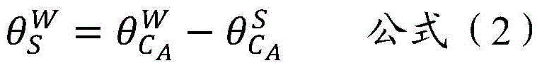
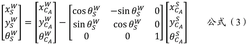
And 305, determining the object pose of the target object in the world coordinate system based on the first target pose of the first position identifier in the world coordinate system and the configured pose of the first position identifier in the coordinate system of the target object (for the convenience of distinguishing, the pose of the target object in the world coordinate system is called the object pose).
For example, the first position identifies a first target pose in the world coordinate system as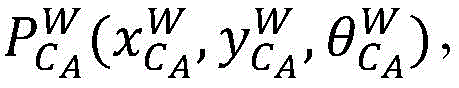 The configured position and posture of the first position marker in the coordinate system of the target object (also called a target shelf) can also be called the posture of the first position marker in the coordinate system of the shelf, and the configured posture is recorded as the posture
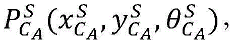 The configured pose is a known pose, which is determined when the first position identifier is pasted on the target object, and can be used as an attribute value of the target object, the accuracy of the configured pose is guaranteed by implementation, generally speaking, higher accuracy can be guaranteed, and the object pose of the target object in a world coordinate system can be recorded as the object pose
 On the basis, the object pose can be calculated by using the formula (2) and the formula (3), of course, the formula (2) and the formula (3) are only an example, and the calculation mode of the object pose is not limited.
And step 306, determining a second target pose of the second position marker in the world coordinate system based on the object pose of the target object in the world coordinate system and the configured pose of the second position marker in the coordinate system of the target object (for the convenience of distinguishing, the pose of the second position marker in the world coordinate system is called a second target pose).
For example, the object pose of the target object in the world coordinate system is The configured position and posture of the second position indicator (i.e. the position indicator b) in the coordinate system of the target object (which may also be referred to as a target shelf) may also be referred to as the posture and posture of the second position indicator in the coordinate system of the shelf, and the configured posture and posture may be referred to as the posture and posture of the second position indicator in the coordinate system of the shelf
 The configured pose is a known pose and is determined when the second position marker is attached to the target objectAnd then, the second position mark can be used as an attribute value of the target object, the accuracy of the configured pose is ensured by implementation, generally speaking, higher accuracy can be ensured, and the second position mark identifies a second target pose in the world coordinate system and is recorded as
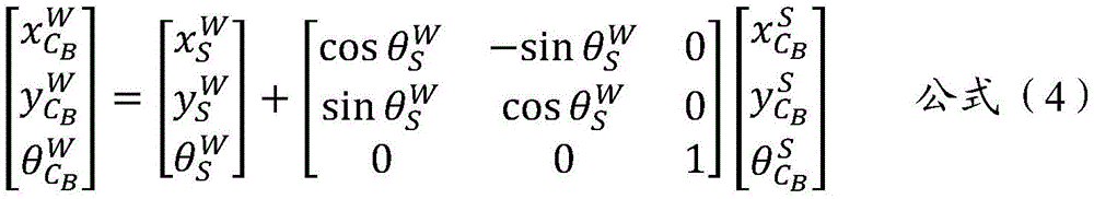
 On the basis, the formula (4) can be used for calculating the second target pose, of course, the formula (4) is only an example, and the calculation mode of the second target pose is not limited.
And 307, determining the estimated pose of the cooperative robot in the world coordinate system based on the second target pose of the second position identifier in the world coordinate system and the second relative pose of the second position identifier in the coordinate system of the cooperative robot (for convenience of distinguishing, the pose of the cooperative robot in the world coordinate system is referred to as the estimated pose).
For example, the cooperative robot is a robot B, the second position identifier is a position identifier B, and the second position identifier is a second target pose in the world coordinate system The second position mark is a second relative pose under the coordinate system of the cooperative robot
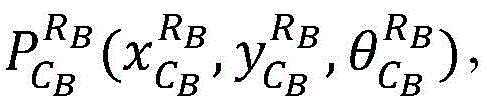 The estimated pose of the cooperative robot in the world coordinate system is recorded as
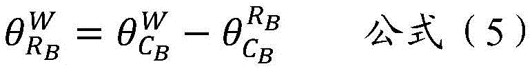
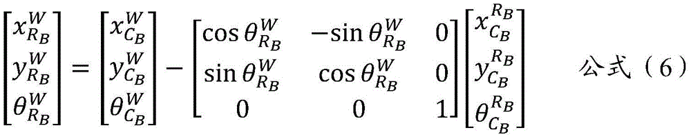
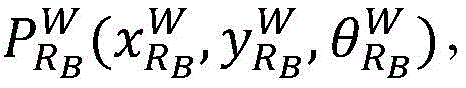 On the basis, the estimated pose can be calculated by adopting the formula (5) and the formula (6), of course, the formula (5) and the formula (6) are only examples, and the calculation mode of the estimated pose is not limited.
And obtaining an estimated pose of the cooperative robot in the world coordinate system, wherein the estimated pose is used for replacing the navigation positioning pose of the cooperative robot in the world coordinate system. Obviously, the estimated pose of the cooperative robot in the world coordinate system is unified to the reference of the target robot with the best positioning quality.
In each of the above formulas, the letters have the following meanings: p: pose (position); w: world system (world), also known as global system; r: a robot or robotic system (robot); rA: robot a or robot a series (robot a); s: shelves (shelf); c: a location identifier (code); cA: a position identifier a (code a); qA: navigation quality/quality of robot a (quality a). The superscript denotes the coordinate system and the subscript denotes the positioning body, for example, represents the pose (P) of the robot A in a world coordinate system (W),
 the coordinate x of the robot A in the world coordinate system (W) is represented, and the meaning of each letter is not repeated in the same way.
And 308, performing cooperative control on the target robot and the cooperative robot in the transportation process of the target object based on the navigation positioning pose of the target robot and the estimated pose of the cooperative robot.
For example, after the navigation positioning pose of the target robot and the estimated pose of the cooperative robot are obtained, the cooperative control of the target robot and the cooperative robot on the transportation process of the target object can be performed.
In a possible embodiment, since the navigation quality data of each robot may change, that is, the target robot may change, steps 301 to 308 may be performed periodically, and in each execution period, the target robot may be determined again, and on the basis of the navigation positioning pose of the target robot, the estimated pose of the cooperative robot is determined again, and then the cooperative control is implemented, which is not described in detail herein.
In the above embodiment, the navigation positioning pose of the target robot with the highest positioning quality is used as the reference of the whole collaborative navigation, and then the estimated pose of the collaborative robot in the world coordinate system is obtained through the pose relationship between the position identifier and the robot (i.e. the first relative pose and the second relative pose) and the pose relationship between the position identifier and the target object (i.e. the configured pose). Compared with the navigation positioning pose of a single robot, the precision of the pose relationship acquired by code scanning and the pose relationship between the position identifier and the target object is very high, so that the whole collaborative navigation precision can be greatly improved. In addition, the target robot with the highest navigation and positioning quality is dynamically changed, so that the robot with high navigation precision can still be relied to obtain higher positioning precision when some robots are inaccurate in navigation (such as laser is shielded).
According to the technical scheme, the robot with the highest navigation and positioning quality can be used as the target robot, the navigation and positioning pose based on the target robot is used as the positioning reference of the whole formation, the navigation and positioning of the cooperative robot with low positioning precision are related to the positioning of the target robot with the highest positioning quality, the whole cooperative navigation precision is improved, the whole environment adaptability and consistency of cooperative navigation are improved, the consistency and precision of the navigation and positioning are obviously improved, and the cooperative navigation and positioning of multiple robots are realized.
In the mode, the navigation results among the robots can be related based on a plurality of position markers (each robot is provided with the position marker, and the position and posture relation among the position markers is known) and the goods shelf, and the accuracy of acquiring the relative position and posture between the position markers and the robots through the reading terminal is very high, so that the navigation positioning consistency and accuracy are obviously improved. The robot navigation positioning with low positioning precision can be associated to the robot positioning with the highest positioning quality by utilizing the code scanning information with higher precision, so that the integral navigation precision is improved.
Based on the same application concept as the method, in the embodiment of the present application, a multi-robot positioning apparatus is provided, when at least two robots transport the same target object together, one of the at least two robots is selected as a target robot, and the remaining robots other than the target robot are cooperative robots, as shown in fig. 4, which is a schematic structural diagram of the apparatus, and the apparatus may include:
an obtaining module 41, configured to obtain a navigation and positioning pose of the target robot in a target coordinate system, where the navigation and positioning pose is a pose of the target robot when the target robot positions itself through data acquired by a sensor; a determining module 42, configured to determine an object pose of the target object in the target coordinate system based on the navigation positioning pose; determining an estimated pose of the collaborative robot in a target coordinate system based on the object pose.
Illustratively, the obtaining module 41 is further configured to: acquiring navigation quality data corresponding to each robot, wherein the navigation quality data are used for reflecting the accuracy of a navigation positioning pose obtained when the robot positions the robot through data acquired by a sensor; based on the navigation quality data corresponding to each robot, the robot with the best navigation positioning quality can be selected from the at least two robots (namely all robots), and the robot with the best navigation positioning quality is determined as the target robot.
For example, the obtaining module 41 is configured to, based on the navigation quality data corresponding to each robot, select a robot with the best navigation positioning quality from the at least two robots, specifically: when the robot positions the robot through data acquired by a radar sensor, the navigation quality data comprises a first matching degree of a laser point outline and a map outline; selecting the robot with the maximum first matching degree as the robot with the best navigation and positioning quality based on the first matching degree corresponding to each robot; and/or when the robot positions itself through data acquired by the vision sensor, the navigation quality data comprises a second matching degree of the image characteristic points and the map characteristic points; selecting the robot with the maximum second matching degree as the robot with the best navigation and positioning quality based on the second matching degree corresponding to each robot; and/or when the robot positions the robot through a Kalman filtering integrated navigation algorithm, the navigation quality data comprise covariance, and the covariance represents the credibility of a navigation positioning result; selecting the robot corresponding to the minimum covariance as the robot with the best navigation positioning quality based on the covariance corresponding to each robot; and/or when the robot positions the robot through two-dimensional code navigation, the navigation quality data comprises a target distance between a two-dimensional code center and an image center; and selecting the robot with the minimum target distance as the robot with the best navigation and positioning quality based on the target distance corresponding to each robot.
For example, the determining module 42, when determining the object pose of the target object in the target coordinate system based on the navigation positioning pose, is specifically configured to: determining a first target pose of a first position identifier under the target coordinate system based on the navigation positioning pose and a first relative pose; wherein the target object comprises a first position marker, the first position marker being detectable by the target robot, the first relative pose being the pose of the first position marker in the coordinate system of the target robot; determining an object pose of the target object in a coordinate system of the target object based on the first target pose and the configured pose of the first position marker in the coordinate system.
For example, before the determining module 42 determines the first target pose of the first position identifier in the target coordinate system based on the navigation positioning pose and the first relative pose, it is further configured to: the first position marker is scanned by the target robot to obtain a first relative pose between the first position marker and the target robot.
For example, the determining module 43, when determining the estimated pose of the cooperative robot in the target coordinate system based on the object pose, is specifically configured to: determining a second target pose of the second location identity in the target coordinate system based on the object pose and a configured pose of the second location identity in the coordinate system of the target object; wherein the target object comprises the second location identity, and the second location identity is detectable by a co-robot; determining an estimated pose of the collaborative robot in the target coordinate system based on the second target pose and a second relative pose of the second position identification in the coordinate system of the collaborative robot.
For example, the determining module 42 identifies a second relative pose in the coordinate system of the cooperative robot based on the second target pose and the second position, and is further configured to, prior to determining the estimated pose of the cooperative robot in the target coordinate system: scanning the second position identification through the cooperative robot to obtain a second relative pose between the second position identification and the cooperative robot.
Based on the same application concept as the method, the embodiment of the present application provides a multi-robot positioning device (i.e. the management entity of the foregoing embodiment), as shown in fig. 5, the multi-robot positioning device includes: a processor 51 and a machine-readable storage medium 52, the machine-readable storage medium 52 storing machine-executable instructions executable by the processor 51; the processor 51 is configured to execute machine executable instructions to implement the multi-robot positioning method disclosed in the above examples of the present application.
Based on the same application concept as the method, embodiments of the present application further provide a machine-readable storage medium, where several computer instructions are stored on the machine-readable storage medium, and when the computer instructions are executed by a processor, the method for positioning multiple robots disclosed in the above examples of the present application can be implemented.
The machine-readable storage medium may be any electronic, magnetic, optical, or other physical storage device that can contain or store information such as executable instructions, data, and the like. For example, the machine-readable storage medium may be: a RAM (random Access Memory), a volatile Memory, a non-volatile Memory, a flash Memory, a storage drive (e.g., a hard drive), a solid state drive, any type of storage disk (e.g., an optical disk, a dvd, etc.), or similar storage medium, or a combination thereof.
The systems, devices, modules or units illustrated in the above embodiments may be implemented by a computer chip or an entity, or by a product with certain functions. A typical implementation device is a computer, which may take the form of a personal computer, laptop computer, cellular telephone, camera phone, smart phone, personal digital assistant, media player, navigation device, email messaging device, game console, tablet computer, wearable device, or a combination of any of these devices.
For convenience of description, the above devices are described as being divided into various units by function, and are described separately. Of course, the functionality of the units may be implemented in one or more software and/or hardware when implementing the present application.
As will be appreciated by one skilled in the art, embodiments of the present application may be provided as a method, system, or computer program product. Accordingly, the present application may take the form of an entirely hardware embodiment, an entirely software embodiment or an embodiment combining software and hardware aspects. Furthermore, embodiments of the present application may take the form of a computer program product embodied on one or more computer-usable storage media (including, but not limited to, disk storage, CD-ROM, optical storage, and the like) having computer-usable program code embodied therein.
The present application is described with reference to flowchart illustrations and/or block diagrams of methods, apparatus (systems), and computer program products according to embodiments of the application. It will be understood that each flow and/or block of the flow diagrams and/or block diagrams, and combinations of flows and/or blocks in the flow diagrams and/or block diagrams, can be implemented by computer program instructions. These computer program instructions may be provided to a processor of a general purpose computer, special purpose computer, embedded processor, or other programmable data processing apparatus to produce a machine, such that the instructions, which execute via the processor of the computer or other programmable data processing apparatus, create means for implementing the functions specified in the flowchart flow or flows and/or block diagram block or blocks.
Furthermore, these computer program instructions may also be stored in a computer-readable memory that can direct a computer or other programmable data processing apparatus to function in a particular manner, such that the instructions stored in the computer-readable memory produce an article of manufacture including instruction means which implement the function specified in the flowchart flow or flows and/or block diagram block or blocks.
These computer program instructions may also be loaded onto a computer or other programmable data processing apparatus to cause a series of operational steps to be performed on the computer or other programmable apparatus to produce a computer implemented process such that the instructions which execute on the computer or other programmable apparatus provide steps for implementing the functions specified in the flowchart flow or flows and/or block diagram block or blocks.
The above description is only an example of the present application and is not intended to limit the present application. Various modifications and changes may occur to those skilled in the art. Any modification, equivalent replacement, improvement, etc. made within the spirit and principle of the present application should be included in the scope of the claims of the present application.
Claims (10)
1. A multi-robot positioning method, wherein when at least two robots collectively transport the same target object, one of the at least two robots is selected as a target robot, and the remaining robots other than the target robot are cooperative robots, the method comprising:
acquiring a navigation positioning pose of the target robot under a target coordinate system; the navigation positioning pose is the pose when the target robot positions the target robot through data acquired by a sensor;
determining an object pose of the target object in the target coordinate system based on the navigation positioning pose;
determining an estimated pose of the collaborative robot in the target coordinate system based on the object pose.
2. The method of claim 1, wherein prior to acquiring the navigational positioning pose of the target robot in the target coordinate system, the method further comprises:
acquiring navigation quality data corresponding to each robot, wherein the navigation quality data are used for reflecting the accuracy of a navigation positioning pose obtained when the robot positions the robot through data acquired by a sensor;
and selecting the robot with the best navigation positioning quality from the at least two robots based on the navigation quality data corresponding to each robot, and determining the robot with the best navigation positioning quality as the target robot.
3. The method of claim 2, wherein selecting the robot with the best navigation positioning quality from the at least two robots based on the navigation quality data corresponding to each robot comprises:
when the robot positions the robot through data acquired by a radar sensor, the navigation quality data comprises a first matching degree of a laser point outline and a map outline; selecting the robot with the maximum first matching degree as the robot with the best navigation and positioning quality based on the first matching degree corresponding to each robot; and/or the presence of a gas in the gas,
when the robot positions the robot through the data acquired by the vision sensor, the navigation quality data comprises a second matching degree of the image characteristic points and the map characteristic points; selecting the robot with the maximum second matching degree as the robot with the best navigation and positioning quality based on the second matching degree corresponding to each robot; and/or the presence of a gas in the gas,
when the robot positions the robot through a Kalman filtering integrated navigation algorithm, navigation quality data comprise covariance, and the covariance represents the credibility of a navigation positioning result; selecting the robot corresponding to the minimum covariance as the robot with the best navigation positioning quality based on the covariance corresponding to each robot; and/or the presence of a gas in the gas,
when the robot positions the robot through two-dimensional code navigation, the navigation quality data comprises a target distance between a two-dimensional code center and an image center; and selecting the robot with the minimum target distance as the robot with the best navigation and positioning quality based on the target distance corresponding to each robot.
4. The method of claim 1, wherein the determining the object pose of the target object in the target coordinate system based on the navigational positioning pose comprises:
determining a first target pose of a first position identifier under the target coordinate system based on the navigation positioning pose and a first relative pose; wherein the target object comprises a first position marker detectable by the target robot, the first relative pose being the pose of the first position marker in the coordinate system of the target robot; determining an object pose of the target object in a target coordinate system based on the first target pose and the configured pose of the first position marker in the target object's coordinate system.
5. The method of claim 4,
prior to the determining a first target pose of a first position identifier in the target coordinate system based on the navigational positioning pose and a first relative pose, the method further comprises:
scanning the first position marker by the target robot to obtain a first relative pose between the first position marker and the target robot.
6. The method of claim 1, wherein the determining an estimated pose of the collaborative robot at the target coordinate system based on the object pose comprises:
determining a second target pose of the second location identity in the target coordinate system based on the object pose and a configured pose of the second location identity in the coordinate system of the target object; wherein the target object comprises the second location identity, and the second location identity is detectable by a co-robot;
determining an estimated pose of the collaborative robot in the target coordinate system based on the second target pose and a second relative pose of the second position identification in the coordinate system of the collaborative robot.
7. The method of claim 6, wherein the determining the estimated pose of the collaborative robot in the target coordinate system based on the second target pose and the second position identification a second relative pose in the coordinate system of the collaborative robot further comprises:
scanning the second position identification through the cooperative robot to obtain a second relative pose between the second position identification and the cooperative robot.
8. A positioning apparatus of multiple robots, wherein one robot of at least two robots is selected as a target robot and the remaining robots other than the target robot are cooperative robots when the at least two robots transport the same target object together, the apparatus comprising:
the system comprises an acquisition module, a navigation positioning module and a navigation positioning module, wherein the acquisition module is used for acquiring a navigation positioning pose of a target robot under a target coordinate system, and the navigation positioning pose is a pose of the target robot when the target robot positions the target robot through data acquired by a sensor;
the determining module is used for determining the object pose of the target object in the target coordinate system based on the navigation positioning pose; determining an estimated pose of the collaborative robot in a target coordinate system based on the object pose.
9. The apparatus of claim 8, wherein the obtaining module is further configured to: acquiring navigation quality data corresponding to each robot, wherein the navigation quality data are used for reflecting the accuracy of a navigation positioning pose obtained when the robot positions the robot through data acquired by a sensor; selecting the robot with the best navigation and positioning quality from the at least two robots based on the navigation quality data corresponding to each robot, and determining the robot with the best navigation and positioning quality as a target robot;
the acquisition module is used for selecting the robot with the best navigation positioning quality from the at least two robots based on the navigation quality data corresponding to each robot, and specifically used for: when the robot positions the robot through data acquired by a radar sensor, the navigation quality data comprises a first matching degree of a laser point outline and a map outline; selecting the robot with the maximum first matching degree as the robot with the best navigation and positioning quality based on the first matching degree corresponding to each robot; and/or when the robot positions itself through the data acquired by the vision sensor, the navigation quality data comprises a second matching degree of the image characteristic points and the map characteristic points; selecting the robot with the maximum second matching degree as the robot with the best navigation and positioning quality based on the second matching degree corresponding to each robot; and/or when the robot positions the robot through a Kalman filtering integrated navigation algorithm, the navigation quality data comprise covariance, and the covariance represents the credibility of a navigation positioning result; selecting the robot corresponding to the minimum covariance as the robot with the best navigation positioning quality based on the covariance corresponding to each robot; and/or when the robot positions the robot through two-dimensional code navigation, the navigation quality data comprises a target distance between a two-dimensional code center and an image center; selecting the robot with the minimum target distance as the robot with the best navigation and positioning quality based on the target distance corresponding to each robot;
the determination module, when determining the object pose of the target object in the target coordinate system based on the navigation positioning pose, is specifically configured to: determining a first target pose of a first position identifier under the target coordinate system based on the navigation positioning pose and a first relative pose; wherein the target object comprises a first position marker detectable by the target robot, the first relative pose being the pose of the first position marker in the coordinate system of the target robot; determining an object pose of the target object in a coordinate system of the target object based on the first target pose and the configured pose of the first position marker in the coordinate system of the target object;
wherein the determination module, prior to determining the first target pose of the first location identifier in the target coordinate system based on the navigational positioning pose and the first relative pose, is further to: scanning the first position marker by the target robot to obtain a first relative pose between the first position marker and the target robot;
wherein the determining module, when determining the estimated pose of the cooperative robot in the target coordinate system based on the object pose, is specifically configured to: determining a second target pose of the second location identity in the target coordinate system based on the object pose and a configured pose of the second location identity in the coordinate system of the target object; wherein the target object comprises the second location identity, and the second location identity is detectable by a co-robot; determining an estimated pose of the collaborative robot in the target coordinate system based on the second target pose and the second position identification second relative pose in the coordinate system of the collaborative robot;
wherein the determination module, based on the second target pose and the second position identification, is further to determine an estimated pose of the collaborative robot in the target coordinate system by: scanning the second position identification through the cooperative robot to obtain a second relative pose between the second position identification and the cooperative robot.
10. A multi-robot positioning apparatus comprising a processor and a machine-readable storage medium having stored thereon machine-executable instructions executable by the processor; the processor is configured to execute machine executable instructions to perform the method steps of any of claims 1-7.
Priority Applications (1)
| Application Number | Priority Date | Filing Date | Title |
|---|---|---|---|
| CN202111656442.8A CN114295118B (en) | 2021-12-30 | 2021-12-30 | Positioning method, device and equipment for multiple robots |
Applications Claiming Priority (1)
| Application Number | Priority Date | Filing Date | Title |
|---|---|---|---|
| CN202111656442.8A CN114295118B (en) | 2021-12-30 | 2021-12-30 | Positioning method, device and equipment for multiple robots |
Publications (2)
| Publication Number | Publication Date |
|---|---|
| CN114295118A true CN114295118A (en) | 2022-04-08 |
| CN114295118B CN114295118B (en) | 2024-01-26 |
Family
ID=80973059
Family Applications (1)
| Application Number | Title | Priority Date | Filing Date |
|---|---|---|---|
| CN202111656442.8A Active CN114295118B (en) | 2021-12-30 | 2021-12-30 | Positioning method, device and equipment for multiple robots |
Country Status (1)
| Country | Link |
|---|---|
| CN (1) | CN114295118B (en) |
Cited By (2)
| Publication number | Priority date | Publication date | Assignee | Title |
|---|---|---|---|---|
| CN115112123A (en) * | 2022-06-27 | 2022-09-27 | 华东理工大学 | Multi-mobile-robot cooperative positioning method and system based on vision-IMU fusion |
| CN116429112A (en) * | 2023-03-27 | 2023-07-14 | 哈尔滨工业大学(深圳) | Multi-robot collaborative positioning method and device, equipment and storage medium |
Citations (5)
| Publication number | Priority date | Publication date | Assignee | Title |
|---|---|---|---|---|
| CN103575272A (en) * | 2013-11-15 | 2014-02-12 | 南开大学 | Method for extracting natural landmarks for mobile robot in forest environment |
| CN105652871A (en) * | 2016-02-19 | 2016-06-08 | 深圳杉川科技有限公司 | Repositioning method for mobile robot |
| CN108303099A (en) * | 2018-06-14 | 2018-07-20 | 江苏中科院智能科学技术应用研究院 | Autonomous navigation method in unmanned plane room based on 3D vision SLAM |
| CN207894430U (en) * | 2018-01-19 | 2018-09-21 | 杭州海康机器人技术有限公司 | Data collector and unmanned plane |
| US10754352B1 (en) * | 2014-06-25 | 2020-08-25 | Santa Clara University | Multi-robot gradient based adaptive navigation system |
-
2021
- 2021-12-30 CN CN202111656442.8A patent/CN114295118B/en active Active
Patent Citations (5)
| Publication number | Priority date | Publication date | Assignee | Title |
|---|---|---|---|---|
| CN103575272A (en) * | 2013-11-15 | 2014-02-12 | 南开大学 | Method for extracting natural landmarks for mobile robot in forest environment |
| US10754352B1 (en) * | 2014-06-25 | 2020-08-25 | Santa Clara University | Multi-robot gradient based adaptive navigation system |
| CN105652871A (en) * | 2016-02-19 | 2016-06-08 | 深圳杉川科技有限公司 | Repositioning method for mobile robot |
| CN207894430U (en) * | 2018-01-19 | 2018-09-21 | 杭州海康机器人技术有限公司 | Data collector and unmanned plane |
| CN108303099A (en) * | 2018-06-14 | 2018-07-20 | 江苏中科院智能科学技术应用研究院 | Autonomous navigation method in unmanned plane room based on 3D vision SLAM |
Non-Patent Citations (1)
| Title |
|---|
| 陈青华,等: "基于STM32的智能家用消毒机器人的设计", 信息技术与信息化, no. 11, pages 202 - 204 * |
Cited By (2)
| Publication number | Priority date | Publication date | Assignee | Title |
|---|---|---|---|---|
| CN115112123A (en) * | 2022-06-27 | 2022-09-27 | 华东理工大学 | Multi-mobile-robot cooperative positioning method and system based on vision-IMU fusion |
| CN116429112A (en) * | 2023-03-27 | 2023-07-14 | 哈尔滨工业大学(深圳) | Multi-robot collaborative positioning method and device, equipment and storage medium |
Also Published As
| Publication number | Publication date |
|---|---|
| CN114295118B (en) | 2024-01-26 |
Similar Documents
| Publication | Publication Date | Title |
|---|---|---|
| KR102819287B1 (en) | Tracking vehicles in a warehouse enviroment | |
| US10127677B1 (en) | Using observations from one or more robots to generate a spatio-temporal model that defines pose values for a plurality of objects in an environment | |
| US10083418B2 (en) | Distributed autonomous robot systems and mehtods | |
| US10209063B2 (en) | Using sensor-based observations of agents in an environment to estimate the pose of an object in the environment and to estimate an uncertainty measure for the pose | |
| CN107687855B (en) | Robot positioning method and device and robot | |
| CN110806211A (en) | Method and device for robot to autonomously explore and establish graph and storage medium | |
| JP2005320074A (en) | Article search and collection apparatus and program | |
| JP2010023950A (en) | Three-dimensional object recognition system and inventory system using the same | |
| US20100284571A1 (en) | Object position estimating system, object position estimating apparatus, object position estimating method, and object position estimating program | |
| WO2023005384A1 (en) | Repositioning method and device for mobile equipment | |
| CN112935703A (en) | Mobile robot pose correction method and system for identifying dynamic tray terminal | |
| US20240393793A1 (en) | Method for estimating posture of moving object by using big cell grid map, recording medium in which program for implementing same is stored, and computer program stored in medium in order to implement same | |
| US11372423B2 (en) | Robot localization with co-located markers | |
| CN114295118A (en) | Multi-robot positioning method, device and equipment | |
| WO2025002358A1 (en) | Methods and systems for locating targets and device docking | |
| McGreavy et al. | Next best view planning for object recognition in mobile robotics | |
| GB2605948A (en) | Warehouse monitoring system | |
| CN118215124B (en) | Asset positioning method, device, equipment and storage medium based on Bluetooth | |
| Xue et al. | Intelligent storage and retrieval systems based on RFID and vision in automated warehouse | |
| CN112528950A (en) | Moving target identification system and method for warehousing channel | |
| CN113984064B (en) | Positioning method and system for indoor mobile robot | |
| Radácsi et al. | A Path Planning Model for Stock Inventory Using a Drone. Mathematics 2022, 10, 2899 | |
| CN112338910A (en) | Space map determination method, robot, storage medium and system | |
| CN113361674A (en) | Encoding and decoding method of nested guide two-dimensional code | |
| Wiech et al. | Overhead vision system for testing swarms and groups of wheeled robots |
Legal Events
| Date | Code | Title | Description |
|---|---|---|---|
| PB01 | Publication | ||
| PB01 | Publication | ||
| SE01 | Entry into force of request for substantive examination | ||
| SE01 | Entry into force of request for substantive examination | ||
| CB02 | Change of applicant information | ||
| CB02 | Change of applicant information |
Address after: 310051 room 304, B / F, building 2, 399 Danfeng Road, Binjiang District, Hangzhou City, Zhejiang Province Applicant after: Hangzhou Hikvision Robot Co.,Ltd. Address before: 310051 room 304, B / F, building 2, 399 Danfeng Road, Binjiang District, Hangzhou City, Zhejiang Province Applicant before: HANGZHOU HIKROBOT TECHNOLOGY Co.,Ltd. |
|
| GR01 | Patent grant | ||
| GR01 | Patent grant |