Detailed Description
Embodiments of the present invention will be described below with reference to the drawings.
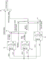
Fig. 1 is a schematic configuration diagram showing essential parts of a vehicle 1. The vehicle 1 includes an internal combustion engine 2, a power generation motor 3, a travel motor 4, a battery 5, and drive wheels 6.
The internal combustion engine 2 may be either a gasoline engine or a diesel engine. The generator motor 3 is driven by the power of the internal combustion engine 2 to generate electric power. The traveling motor 4 is driven by electric power of the battery 5 to drive the drive wheels 6. The running motor 4 also has a so-called regeneration function of regenerating deceleration energy as electric power by being rotated in accordance with the rotation of the drive wheels 6 at the time of deceleration or the like. The battery 5 is charged with the electric power generated by the generator motor 3 and the electric power regenerated by the traveling motor 4.
The vehicle 1 has a 1 st power transmission path 21 and a 2 nd power transmission path 22. The 1 st power transmission path 21 is used to transmit power between the running motor 4 and the drive wheels 6. The 2 nd power transmission path 22 is used to transmit power between the internal combustion engine 2 and the electric power generating motor 3. The 1 st power transmission path 21 and the 2 nd power transmission path 22 are independent power transmission paths, that is, power transmission paths that do not transmit power from one of the 1 st power transmission path 21 and the 2 nd power transmission path 22 to the other.
The 1 st power transmission path 21 includes: a 1 st reduction gear 11 provided on a rotary shaft 4a of the traveling motor 4; a 2 nd reduction gear 12 meshed with the 1 st reduction gear 11; a 3 rd reduction gear 13 which is provided coaxially with the 2 nd reduction gear 12 and meshes with the differential gear 14; and a differential gear 14 provided in the differential case 15.
The 2 nd power transmission path 22 includes: a 4 th reduction gear 16 provided on the output shaft 2a of the internal combustion engine 2; a 5 th reduction gear 17 meshed with the 4 th reduction gear 16; and a 6 th reduction gear 18 provided on the rotary shaft 3a of the power generation motor 3 and meshing with the 5 th reduction gear 17.
The 1 st power transmission path 21 and the 2 nd power transmission path 22 each have no element for interrupting power transmission. That is, the 1 st power transmission path 21 and the 2 nd power transmission path 22 are always in a state of being transmitted with power.
The 2 nd power transmission path 22 constitutes a power transmission path of the power transmission system 23. The power transmission system 23 includes the internal combustion engine 2 and the generator motor 3, and is configured to transmit power from the generator motor 3 to the internal combustion engine 2 when the motor of the internal combustion engine 2 is operated.
The vehicle 1 also has a controller 30 as a control section. The controller 30 includes an engine controller 31 that controls the internal combustion engine 2, a generator motor controller 32 that controls the generator motor 3, a traveling motor controller 33 that controls the traveling motor 4, and an integrated controller 34 that collectively controls the vehicle 1.
The engine controller 31 is constituted by a microcomputer having a Central Processing Unit (CPU), a Read Only Memory (ROM), a Random Access Memory (RAM), and an input/output interface (I/O interface). The same applies to the generator motor controller 32, the traveling motor controller 33, and the integrated controller 34. The engine controller 31, the generator motor controller 32, and the traveling motor controller 33 are connected to each other by a CAN-standard bus via an integrated controller 34 so as to be communicable with each other.
Signals from various sensors/switches including a rotation speed sensor 81 for detecting a rotation speed NE of the internal combustion engine 2, an accelerator opening sensor 82 for detecting an accelerator opening APO indicating a stepping amount of an accelerator pedal, a water temperature sensor 83 for detecting a water temperature THW of the internal combustion engine 2, and a vehicle speed sensor 84 for detecting a vehicle speed VSP are input to the controller 30. The signal is input to the integrated controller 34 directly or via another controller such as the engine controller 31.
The vehicle 1 constitutes a series hybrid vehicle that drives a drive wheel 6 by a running motor 4 using electric power of a generator motor 3 that is driven by power of an internal combustion engine 2 to generate electric power.
Fig. 2 is an explanatory diagram of the shift position and the drive mode. The vehicle 1 has a shifter 91. The shifter 91 is a device for switching the shift positions by the operation of the driver, and is operated by the driver by the operation of a shift lever or the operation of a switch for a valve corresponding to each shift position.
The shifter 91 is a momentary shifter. With the momentary-type shifter 91, the shift lever released from the driver's operation is automatically returned to the original position. The shift position selected by the driver operation is displayed on a shift position display provided in the vehicle interior together with a drive mode described later. The gear indicator can visually confirm the selected gear.
The gears that can be selected by the shifter 91 include a D gear as a 1 st forward gear and a B gear as a 2 nd forward gear, in addition to a P gear (parking gear), an R gear (parking gear), and an N gear (neutral gear).
The D-range and the B-range are selected by a shift lever operation for a D/B valve common to them. By operating a shift lever for the D/B valve, the B range is selected when the D range is selected, and the D range is selected when the B range is selected. When a gear other than the D-range and the B-range is selected, the D-range is selected by a shift lever operation for the D/B valve. The D-range and the B-range are further described below.
The vehicle 1 has a drive mode switch 92. The drive mode switch 92 is a switch for changing the drive mode by the operation of the driver.
The driving modes include an N mode, an S mode, and an ECO mode. The N-mode is a mode (normal regeneration mode) in which acceleration is performed by an accelerator pedal operation. Therefore, while the accelerator pedal is operated in the N mode, regenerative deceleration is not performed, and regenerative deceleration is performed while the accelerator pedal is off. The S mode and the ECO mode are modes (single pedal mode) in which acceleration and regenerative deceleration are performed by an accelerator pedal operation, and the ECO mode is a mode more suitable for fuel economy operation than the S mode. Each time the drive mode switch 92 is pressed, the drive mode is changed in the order of N mode, S mode, and ECO mode. The ECO mode is resumed to the N mode.
In the vehicle 1, the combination with the selected drive mode constitutes an ND mode in which the D range is combined with the N mode, an SD mode in which the D range is combined with the S mode, and an ECO-D mode in which the ECO mode is combined. Similarly, the B range is combined with the selected drive mode to constitute NB mode, SB mode, ECO-B mode.
The B range is set to a range in which the deceleration of the vehicle 1 generated by regeneration of the running motor 4 is larger than the D range in the accelerator-off state. In other words, in the B range, the target deceleration is set larger than in the D range. A larger deceleration indicates a larger degree of deceleration (larger absolute value of deceleration). The same is true for the target deceleration. In the B range, the absolute value of the regenerative power generated by the running motor 4 is larger than that in the D range, and as a result, the deceleration is increased. In the SD mode and the ECO-D mode, the regenerative power of the driving motor 4 is increased in the accelerator-off state as compared with the ND mode, and as a result, the deceleration is increased. In the following description, the N mode is also referred to as a normal regeneration mode, and the S mode and the ECO mode are also referred to as a strong regeneration mode.
Fig. 3 is a block diagram showing the processing function of the integrated controller 34. Fig. 3 shows a process of calculating the target engine rotational speed NE-T and the target engine torque TQ-T. The integrated controller 34 includes a target driving force calculation unit 341, an engine start/stop calculation unit 342, a target power calculation unit 343, and a target ENG operating point calculation unit 344. Note that each of the arithmetic units represents an arithmetic processing function and does not represent a physical configuration. The same applies to fig. 4 and 5 described later.
The target driving force calculation unit 341 calculates the target driving force DP _ T of the running motor 4 based on the vehicle speed VSP and the accelerator opening APO. The target driving force DP _ T can be set in advance using map data according to the vehicle speed VSP and the accelerator opening APO. The target driving force calculation unit 341 calculates a target regenerative power, which is a negative target driving force DP _ T during regeneration. The calculated target driving force DP _ T is input to the target electric power calculating unit 343. Further, the target driving force DP _ T is also input to the running motor controller 33, which is not shown in fig. 3. The running motor controller 33 controls the driving torque of the running motor 4 based on the target driving force DP-T.
The engine start/stop calculation unit 342 determines whether to start or stop the internal combustion engine 2 based on the vehicle speed VSP and the charging rate SOC of the battery 5, and activates the engine start flag when the engine is started, and activates the engine stop flag when the engine is stopped. Any flag is input to the target power calculation unit 343. The details of the calculation performed by the engine start/stop calculation unit 342 will be described later.
The target power calculation unit 343 calculates the target power EP _ T for power generation or discharge by the power generation motor 3 based on the target driving force DP _ T. The power generation motor 3 is driven by the internal combustion engine 2 during power generation, and the internal combustion engine 2 is driven by the power generation motor 3, that is, the motor operation is performed during discharge. However, when the engine stop flag is input from the engine start/stop calculation unit 342, the power generation motor 3 is not driven by the internal combustion engine 2.
When the positive target driving force DP _ T is input, the target power calculation unit 343 calculates the target power EP _ T for power generation. The target power for power generation EP _ T is corrected by adding power according to various power generation request flags. The target power EP _ T for power generation is calculated with the upper limit of the upper limit charging power.
When the negative target driving force DP _ T is input, the target power calculation unit 343 calculates the target power EP _ T for discharge. The target electric power EP _ T for discharge is calculated with the absolute value of the upper limit discharge electric power as an upper limit. The calculated target power EP _ T is input to the target ENG operation point calculation unit 344.
The target ENG operation point calculation unit 344 calculates the target operation point of the internal combustion engine 2 based on the target electric power EP _ T. The target operating point may be set in advance using map data according to the target power EP _ T. When the motor operation (motoring) that is the discharge is performed, the target ENG operation point calculation unit 344 calculates the target rotation speed NE _ T and the target torque TQ _ T as the target operation point. The calculated target rotation speed NE _ T is input to the generator motor controller 32, and the target torque TQ _ T is input to the engine controller 31.
The engine controller 31 controls the internal combustion engine 2 based on the input target torque TQ _ T. The generator motor controller 32 controls the generator motor 3 based on the input target rotation speed NE _ T. This causes the motor of the internal combustion engine 2 to operate, thereby consuming electric power.
Here, the contents of the calculation performed by the engine start/stop calculation unit 342 will be described with reference to fig. 4 and 5.
In the deceleration in the B range, the regenerative electric power is increased as compared with the deceleration in the normal regeneration mode in the D range, and therefore the rising speed of the charging rate SOC is increased. Further, the charging rate SOC has an upper limit that can be charged, and if the upper limit is reached during deceleration, the regenerative power must be reduced. For example, when the state of charge SOC is greater than a predetermined value, the target driving force calculation unit 341 decreases the negative target driving force DP _ T, that is, the target regenerative power, during regeneration. By "decreasing" is meant approaching zero. The predetermined value is set to 80%, for example.
That is, even when the driver requests a large deceleration and selects the B range, if the charging rate SOC reaches the upper limit, the deceleration decreases, which may cause an uncomfortable feeling to the driver. In particular, if power generation based on charge rate control for starting power generation by starting the internal combustion engine 2, power generation control based on various power generation requests, or the like is executed because the driver requests a large target driving force, or the charge rate SOC is less than or equal to a predetermined value, the rate of increase in the charge rate SOC increases.
Therefore, when the B range is selected, the integrated controller 34 of the present embodiment performs control so that the opportunity to perform power generation by the internal combustion engine 2 is reduced, compared to when the D range is selected, in order to suppress an increase in the charging rate SOC. In other words, the integrated controller 34 makes it difficult to start and easy to stop the internal combustion engine 2 when the B range is selected, as compared with when the D range is selected. Specifically, the engine start/stop calculation unit 342 sets a threshold value for determining start or stop based on the shift position and the mode, compares the threshold value with the vehicle request output to determine whether to start or stop the internal combustion engine 2, and inputs the determination result to the target power calculation unit 343. The vehicle request output is an output required to cause the vehicle to travel in accordance with a request of the driver. In the present embodiment, a case will be described in which the electric power required by the traveling motor 4 to achieve the target driving force DP _ T (hereinafter, also referred to as target driving power) is the vehicle requested output.
[ Start judgment ]
Fig. 4 is a block diagram showing a processing function executed by the engine start/stop calculation unit 342 to determine whether or not to start the internal combustion engine 2.
The starting 1 st threshold value calculation unit 41 calculates the starting 1 st threshold value based on the vehicle speed VSP and the charging rate SOC. The starting 1 st threshold is electric power for determining whether or not to start the internal combustion engine 2 in the case where the B range is selected. That is, if the vehicle request output is equal to or greater than the starting 1 st threshold value in the case where the B range is selected, the internal combustion engine 2 is started.
The 1 st threshold value map for starting is mapped in advance and stored in the integrated controller 34. The start-up 1 st threshold value is set to a value smaller when the vehicle speed VSP is high than when the vehicle speed VSP is low if the charging rate SOC is the same, and larger when the charging rate SOC is high if the charging rate SOC is the same. The reason why the starting 1 st threshold value is set to be large when the charging rate SOC is high in the same vehicle speed VSP is that the higher the charging rate SOC, that is, the closer to the upper limit of the chargeable range, the more difficult it is to start the internal combustion engine 2. The characteristics of the case of the same SOC will be described later. The calculated 1 st threshold for activation is input to the 1 st switch 44.
The correspondence map described in the starting 1 st threshold value calculation unit 41 of fig. 4 shows an outline of the characteristic of the starting 1 st threshold value, and more specific characteristics will be described later. The same applies to the corresponding diagrams of the starting 2 nd threshold value calculating unit 42 and the starting 3 rd threshold value calculating unit 43 described below.
The starting 2 nd threshold value calculating unit 42 calculates the starting 2 nd threshold value based on the vehicle speed VSP and the charging rate SOC, as in the starting 1 st threshold value calculating unit 41. The start threshold 2 is a threshold for determining whether to start the internal combustion engine 2 in the strong regeneration mode in the D range. The characteristic of the starting threshold value 2 is basically the same as that of the starting threshold value 1, and the threshold value is different in magnitude when the vehicle speed VSP is the same and the SOC is the same. This will be described later. The calculated 2 nd threshold value for activation is input to the 1 st switch 44.
The 1 st switch 44 selects the 1 st threshold for starting if the B range flag is input, and selects the 2 nd threshold for starting if the B range flag is not input. The B range flag is a flag that is input when the B range is selected. The threshold value selected here is input to the 2 nd switch 45.
The starting 3 rd threshold value calculator 43 calculates the starting 3 rd threshold value based on the vehicle speed VSP and the charging rate SOC, as in the starting 1 st threshold value calculator 41 and the starting 2 nd threshold value calculator 42. The starting threshold 3 is a threshold for determining whether to start the internal combustion engine 2 in the normal regeneration mode in the D range. The characteristic of the starting threshold value 3 is basically the same as the starting threshold value 1 and the starting threshold value 2, and the magnitude is different when the vehicle speed VSP is the same and the SOC is the same. This will be described later. The calculated 3 rd threshold for activation is input to the 2 nd switch 45.
The 2 nd switch 45 selects the threshold selected by the 1 st switch 44 if the strong regeneration mode flag is input, and selects the 3 rd threshold for starting if not input. The strong reproduction mode flag is a flag input in the case of the SD mode or ECO-D mode. The threshold value selected here is input to the activation determination section 46.
The start determination unit 46 compares the threshold selected by the 2 nd switch 45 with the vehicle request output, and inputs the engine start flag to the target power calculation unit 343 when the vehicle request output is equal to or greater than the threshold.
Here, the magnitude relation among the starting 1 st threshold, the starting 2 nd threshold, and the starting 3 rd threshold will be described. Fig. 6 shows the starting 1 st threshold, the starting 2 nd threshold, and the starting 3 rd threshold at the same charging rate SOC as the vehicle speed VSP on the horizontal axis and the electric power (starting determination electric power) having the threshold on the vertical axis. Any threshold value is greater when vehicle speed VSP is low than when vehicle speed VSP is high. The vehicle speed is a constant value in the low vehicle speed region and the high vehicle speed region, and is a value that decreases as the vehicle speed increases in the intermediate vehicle speed region.
This characteristic is provided to prevent the engine sound generated during power generation from being transmitted to the vehicle occupant as much as possible. That is, the engine is made difficult to start by increasing the threshold value in a situation where the engine sound is conspicuous as when traveling on a city street. On the other hand, in the high vehicle speed region, the requested power of the running motor 4 is large, and road noise, wind noise, and the like are large, so the engine sound is hard to become conspicuous, and therefore the threshold value is reduced compared to the low vehicle speed region, so that the chance of power generation increases. The intermediate vehicle speed region is between the low vehicle speed region and the high vehicle speed region, and therefore the threshold value is reduced as the vehicle speed increases.
In the low vehicle speed region and the medium vehicle speed region, the 1 st threshold for activation > the 2 nd threshold for activation > the 3 rd threshold for activation, and in the high vehicle speed region, the 1 st threshold for activation > the 2 nd threshold for activation ═ the 3 rd threshold for activation. This is because the rising speed of the charging rate SOC increases as the deceleration increases, and therefore, it becomes more difficult to start the internal combustion engine 2 as the deceleration increases.
The characteristic shown in fig. 6 is an example, and if the threshold value is larger in the low vehicle speed region than in the high vehicle speed region, the characteristic is not limited to the example of fig. 6. For example, the characteristic shown in fig. 4 may be such that the threshold value decreases at a constant slope from a low vehicle speed region toward a high vehicle speed region. In addition, if the relationship of the 1 st threshold for starting > the 2 nd threshold for starting > the 3 rd threshold for starting is established, the thresholds may be the same in magnitude in the low vehicle speed region and the high vehicle speed region.
As described above, the integrated controller 34 switches the 1 st threshold for starting, the 2 nd threshold for starting, or the 3 rd threshold for starting according to the current running range and running mode, and determines whether or not to start the internal combustion engine 2. Thus, the higher the deceleration, the more difficult it is to start the internal combustion engine 2, and the increase in the charging rate SOC can be suppressed.
[ stop determination ]
Fig. 5 is a block diagram showing a processing function executed by the engine start/stop calculation unit 342 to determine whether or not to stop the internal combustion engine 2.
Fig. 5 is a diagram in which the 1 st threshold value calculation unit 41 for starting in fig. 4 is changed to the 1 st threshold value calculation unit 51 for stopping, the 2 nd threshold value calculation unit 42 for starting in fig. 4 is changed to the 2 nd threshold value calculation unit 52 for stopping, the 3 rd threshold value calculation unit 43 for starting in fig. 4 is changed to the 3 rd threshold value calculation unit 53 for stopping, and the start determination unit 46 in fig. 4 is changed to the stop determination unit 56.
The stop 1 st threshold value calculation unit 51 calculates the stop 1 st threshold value based on the vehicle speed VSP and the charging rate SOC. The stop 1 st threshold is electric power for determining whether or not to stop the internal combustion engine 2 in the case where the B range is selected. That is, in the case where the B range is selected, if the vehicle requested output is less than the 1 st threshold for stopping, the internal combustion engine 2 is stopped.
The 1 st threshold value map for stopping is mapped in advance and stored in the integrated controller 34. The 1 st threshold for stopping is set to a value that is smaller when the vehicle speed VSP is high than when the vehicle speed VSP is low if the charging rate SOC is the same, and is larger when the charging rate SOC is high if the charging rate SOC is the same. The reason why the 1 st threshold for stopping is set to be large when the charging rate SOC is high in the same vehicle speed VSP is that the higher the charging rate SOC is, that is, the closer to the upper limit of the chargeable amount, the easier it is to stop the internal combustion engine 2. The characteristics of the case of the same SOC will be described later. The calculated 1 st threshold for stopping is input to the 1 st switch 54.
The correspondence table described in the stop 1 st threshold value calculation unit 51 of fig. 5 indicates an outline of the characteristics of the stop 1 st threshold value, and more specific characteristics will be described later. The same applies to the corresponding diagrams of the starting 2 nd threshold value calculating unit 42 and the starting 3 rd threshold value calculating unit 43 described below.
The stopping threshold value 2 calculating unit 52 calculates the stopping threshold value 2 based on the vehicle speed VSP and the charging rate SOC, as in the stopping threshold value 1 calculating unit 51. The stop threshold 2 is a threshold for determining whether to stop the internal combustion engine 2 in the strong regeneration mode in the D range. The stop 2 nd threshold value has basically the same characteristics as the stop 1 st threshold value, and has a different magnitude for the same vehicle speed VSP and the same SOC. This will be described later. The calculated 2 nd threshold value for stopping is input to the 1 st switch 54.
The 1 st switch 54 selects the 1 st threshold value for stopping if the B range flag is input, and selects the 2 nd threshold value for stopping if not input.
The stopping 3 rd threshold value calculating unit 53 calculates the stopping 3 rd threshold value based on the vehicle speed VSP and the charging rate SOC, as in the stopping 1 st threshold value calculating unit 51 and the stopping 2 nd threshold value calculating unit 52. The stop 3 rd threshold is a threshold for determining whether to stop the internal combustion engine 2 in the normal regeneration mode in the D range. The stop 3 rd threshold has basically the same characteristics as the stop 1 st threshold and the stop 2 nd threshold, and has a different magnitude when the vehicle speed VSP is the same and the SOC is the same. This will be described later. The calculated 3 rd threshold for stopping is input to the 2 nd switch 55.
The 2 nd switch 55 selects the threshold value selected by the 1 st switch 54 if the strong regeneration mode flag is input, and selects the 3 rd threshold value for stopping if not input. The threshold selected here is input to the stop determination unit 56.
The stop determination unit 56 compares the threshold selected by the 2 nd switch 55 with the vehicle request output, and inputs the engine stop flag to the target power calculation unit 343 when the vehicle request output is smaller than the threshold.
Here, the magnitude relationship among the 1 st threshold for stopping, the 2 nd threshold for stopping, and the 3 rd threshold for stopping will be described. Fig. 7 shows the 1 st threshold for stopping, the 2 nd threshold for stopping, and the 3 rd threshold for stopping at the same charging rate SOC as the electric power (start determination electric power) having the vehicle speed VSP on the horizontal axis and the threshold on the vertical axis. Any threshold value is greater when vehicle speed VSP is low than when vehicle speed VSP is high. In the middle vehicle speed region and the high vehicle speed region, the threshold value is constant.
This characteristic is provided to prevent the engine sound generated during power generation from being transmitted to the vehicle occupant as much as possible. That is, the engine is easily stopped in a situation where the engine sound is conspicuous as when traveling on a city street. On the other hand, the greater the requested power of the running motor 4, and the greater the road noise, wind noise, and the like, the more difficult it is for the engine sound to become noticeable, so the threshold is reduced compared to the low vehicle speed region, so that the chances of power generation increase.
The magnitude relationship of the stop thresholds is 1 st stop threshold > 3 rd stop threshold > 2 nd stop threshold. This is because the higher the deceleration, the higher the rising speed of the charging rate SOC, and therefore, in the case of the B range in which the deceleration is relatively large, the internal combustion engine 2 is more easily stopped than in the case of the D range in which the deceleration is relatively small.
The characteristic shown in fig. 7 is an example, and if the threshold value is larger in the low vehicle speed region than in the high vehicle speed region, the characteristic is not limited to the example of fig. 7. For example, the characteristic shown in fig. 5 may be such that the threshold value decreases at a constant slope from a low vehicle speed region toward a high vehicle speed region. In addition, if the relationship of 1 st threshold for stopping > 3 rd threshold for stopping > 2 nd threshold for stopping is established, the thresholds may be the same size in the low vehicle speed region and the high vehicle speed region.
As described above, the integrated controller 34 switches the 1 st threshold value for stopping, the 2 nd threshold value for stopping, or the 3 rd threshold value for stopping according to the current running range and running mode, and determines whether or not to stop the internal combustion engine 2. Thus, the higher the deceleration, the more easily the internal combustion engine 2 is stopped, and the increase in the charging rate SOC can be suppressed.
Fig. 8 is a time chart in the case where the B range is driven in the high vehicle speed region. Until a timing T1, when the internal combustion engine 2 is stopped and running at a constant vehicle speed, the accelerator pedal opening degree starts to decrease and then becomes zero at a timing T1. That is, the vehicle request output decreases from the timing T1, and the charging rate SOC is raised by the decelerating regeneration.
Then, if the accelerator pedal opening is stepped on for reacceleration at timing T2, the vehicle request output increases and the charging rate SOC decreases. At this time, the vehicle request output does not reach the starting 1 st threshold value, and therefore the internal combustion engine 2 is not started. This can suppress further increase in the charging rate SOC. After the timing T3, the accelerator pedal opening degree is decreased to the same level as that before the timing T1, and the vehicle request output is also decreased accordingly. That is, according to the present embodiment, the internal combustion engine 2 is not started during the period shown in fig. 8.
If the 1 st threshold for starting in the B range is not set to be greater than the 2 nd threshold for starting in the D range and the 3 rd threshold for starting in the 3 rd range, the internal combustion engine 2 is started and power generation is started when the vehicle request output immediately after the timing T2 exceeds the 2 nd threshold for starting and the 3 rd threshold for starting. Thereby, the charging rate SOC may be further increased. After the accelerator pedal opening becomes constant after the timing T3, the vehicle requested output is also greater than the 3 rd threshold for stopping, and therefore the internal combustion engine 2 is not stopped. Therefore, when deceleration is performed thereafter, the charging rate SOC may reach the upper limit in the middle of deceleration.
In contrast, in the present embodiment, as described above, the internal combustion engine 2 is not started during the period shown in fig. 8, and therefore, an increase in the charging rate SOC can be suppressed. Thus, the charging rate SOC reaches the upper limit in the middle of deceleration, and therefore the possibility of a change in deceleration can be suppressed.
Further, if the internal combustion engine 2 is operated before the timing T1, if the stop threshold value for the B range is the same as the 2 nd threshold value for the strong regeneration mode of the D range, the internal combustion engine 2 is not stopped, and therefore the rate of increase of the charging rate SOC is higher than that in the case shown in fig. 8. In contrast, in the present embodiment, since the 1 st threshold for stopping is set to be larger than the 2 nd threshold for stopping, the internal combustion engine 2 is stopped immediately after the timing T1 elapses. This can suppress an increase in the state of charge SOC.
[ 1 st modification ]
A modified example of the stop threshold value will be described. The present modification is also included in the scope of the present invention.
Fig. 9 shows the 1 st threshold for stopping, the 2 nd threshold for stopping, and the 3 rd threshold for stopping according to the modification, as in fig. 7. The characteristic in which the threshold value is reduced in the high vehicle speed region compared to the parking vehicle speed region is the same as fig. 7.
However, in the present modification, in the vehicle speed region lower than the 1 st speed threshold value of the low and medium vehicle speed region, the 1 st threshold value for stopping is equal to or larger than the 2 nd threshold value for stopping and smaller than the 3 rd threshold value for stopping. In a speed region greater than or equal to the 2 nd speed threshold value in the high vehicle speed region, the 3 rd threshold value for stopping is smaller than the 1 st threshold value for stopping and the 2 nd threshold value for stopping. That is, the relationship between the 1 st threshold value for stopping and the 2 nd threshold value for stopping is basically the same as that in the case of fig. 7, and the 3 rd threshold value for stopping is different from that in fig. 7 in that it is larger than the 1 st threshold value for stopping in the low and medium vehicle speed region and smaller than the 1 st threshold value for stopping in the high vehicle speed region. The 1 st speed threshold and the 2 nd speed threshold are values that can be set arbitrarily, and are set appropriately according to the specifications of the vehicle to which the present modification is applied, and the like.
Since the internal combustion engine 2 is not operated as much as possible in the low vehicle speed region, the 3 rd threshold for stopping is set to be large, and the internal combustion engine 2 is easily stopped. However, since the electric power required for driving the traveling motor 4 is large in the high vehicle speed region, if the 3 rd threshold for stopping is set to the maximum value also in the high vehicle speed region, the charging rate SOC may be excessively reduced. Therefore, it is difficult to reduce the 3 rd threshold for stopping to stop the internal combustion engine 2 in the high vehicle speed region, whereby it is possible to suppress an excessive reduction in the charging rate SOC.
[ modification 2 ]
A modified example of the start threshold and the stop threshold will be described. The present modification is also included in the scope of the present invention.
Fig. 10 is a diagram showing the relationship among the starting 1 st threshold, the starting 2 nd threshold, and the starting 3 rd threshold according to the modification. The point of difference from fig. 6 is that the horizontal axis represents the charging rate SOC.
In the above embodiment, the starting 1 st threshold value, the starting 2 nd threshold value, and the starting 3 rd threshold value are calculated using a table in which the horizontal axis represents the vehicle speed VSP, but a table in which the horizontal axis represents the charging rate SOC as shown in fig. 10 may be used. In this case, as in the above-described embodiment, the starting 1 st threshold, the starting 2 nd threshold, and the starting 3 rd threshold are all smaller as the vehicle speed VSP is higher at the same charging rate SOC.
In fig. 10, basically, the 1 st threshold for activation > the 2 nd threshold for activation > the 3 rd threshold for activation, and in a region where the charge rate SOC is small, the 1 st threshold for activation is the 2 nd threshold for activation > the 3 rd threshold for activation. This is because, as in the case where the vehicle speed VSP is plotted on the horizontal axis, the higher the regenerative power is, the more difficult it is to start the internal combustion engine 2, and the higher the charging rate SOC in the B range can be suppressed. The boundary between the region where the 1 st threshold for activation > the 2 nd threshold for activation and the region where the 1 st threshold for activation becomes the 2 nd threshold for activation can be arbitrarily set, and is appropriately set according to the specifications of the vehicle to which the present modification is applied, or the like.
Fig. 11 is a diagram showing the relationship among the 1 st threshold for stopping, the 2 nd threshold for stopping, and the 3 rd threshold for stopping according to the modification. The difference from fig. 7 is that the horizontal axis represents the charging rate SOC.
In the above embodiment, the 1 st threshold for stopping, the 2 nd threshold for stopping, and the 3 rd threshold for stopping were calculated using the table in which the horizontal axis is the vehicle speed VSP, but a table in which the horizontal axis is the charging rate SOC as shown in fig. 11 may be used. In this case, as in the above embodiment, the 1 st threshold for stopping, the 2 nd threshold for stopping, and the 3 rd threshold for stopping are all smaller as the vehicle speed VSP is higher at the same charging rate SOC.
In fig. 11, the 1 st threshold for stopping is larger than the 2 nd threshold for stopping, and the 3 rd threshold for stopping is larger than the 1 st threshold for stopping. The reason why the 1 st threshold for stopping is larger than the 2 nd threshold for stopping is to make it easier to stop the internal combustion engine 2 in the B range in which the regenerative power is relatively large than in the strong regeneration mode in the D range in which the regenerative power is relatively small, thereby suppressing an increase in the charging rate SOC. The reason why the 3 rd threshold for stopping is larger than the 1 st threshold for stopping is because the regenerative electric power is small in the normal regeneration mode using the D range of the 3 rd threshold for stopping, and therefore if a small threshold is set, the opportunity for the vehicle to request an output lower than the threshold substantially disappears.
[ modification 3 ]
A modified example of the vehicle request output will be described. The present modification is also included in the scope of the present invention.
In the above embodiment, the target drive power is used as the vehicle request output, and the start and stop of the internal combustion engine 2 are determined by comparing the target drive power with the threshold value. In contrast, in the present modification, the target driving force DP _ T is used as the vehicle requested output, and the start and stop of the internal combustion engine 2 are determined by comparing the target driving force DP _ T with the threshold value.
The target drive power is the power required by the running motor 4 to achieve the target drive force DP _ T. Therefore, the target drive power may be referred to as an output obtained by converting the target drive power DP _ T into the target torque of the running motor 4, converting the current vehicle speed VSP into the rotation speed of the running motor 4, and multiplying the obtained target torque by the rotation speed. That is, it can be said that the target driving force DP _ T is substantially the same as the target driving power.
In addition, as the vehicle requested output is changed from the target drive power to the target drive power DP _ T, it is necessary to change the threshold for activation and the threshold for deactivation from the threshold for power to the threshold for drive power. In the present modification, values obtained by converting the threshold for activation and the threshold for deactivation in the above-described embodiment and modification from electric power to driving force are used. That is, the start threshold and the stop threshold of the present modification are substantially the same as those of the above-described embodiment and modification. Therefore, the start threshold and the stop threshold of the present modification also have the characteristics shown in fig. 6, 7, and 9-11.
As described above, even in the case where the target drive power is used as the vehicle request output, the same operational effects as those of the above-described embodiment can be obtained.
[ Effect ]
In the present embodiment, a control method of a series hybrid vehicle is provided in which a battery 5 is charged with electric power generated by a power generation motor 3 driven by power of an internal combustion engine 2 and electric power regenerated by a travel motor 4, drive wheels are driven by the travel motor 4 using the electric power of the battery 5, power generation by the internal combustion engine 2 is started if a vehicle request output exceeds a threshold for starting (power generation start threshold), power generation by the internal combustion engine 2 is stopped if the vehicle request output is lower than a threshold for stopping (power generation stop threshold), and deceleration generated by regeneration of the travel motor is increased in a B range (2 nd forward range) as compared with a D range (1 st forward range). The regeneration of the traveling motor described here is performed with the accelerator pedal off. In this control method, at least one of the start threshold value and the stop threshold value in the case where the B range is selected is larger than the start threshold value and the stop threshold value in the case where the D range is selected.
Thus, at the time of acceleration before the start of deceleration (for example, at timing T2-T3 in fig. 8), the frequency at which the requested driving force (or the requested electric power) exceeds the threshold for activation and the power generation is started is reduced, and the increase in the charging rate SOC can be suppressed. Further, during deceleration or constant speed travel (for example, at or after timing T1-T2 or T3 in fig. 8), the frequency at which the requested driving force (or the requested electric power) falls below the stop threshold and power generation starts increases, and an increase in the charging rate SOC can be suppressed. As a result, the regenerative power is restricted, and the frequency of the change in deceleration can be reduced. That is, the frequency at which deceleration changes during deceleration can be reduced.
In the present embodiment, the D range includes: a normal regeneration mode; and a strong regeneration mode in which a deceleration generated by regeneration of the running motor is larger than that of the normal regeneration mode and smaller than that of the B range. Further, the threshold for starting in the D range (starting threshold 2) in the strong regeneration mode is larger than the threshold for starting in the D range (starting threshold 3) in the normal regeneration mode, and the threshold for starting in the B range (starting threshold 1) is larger than the starting threshold 3. Thus, the larger the regenerative electric power is, the more difficult it is to start the internal combustion engine 2.
In the present embodiment, when the charging rate SOC of the battery 5 charged with the electric power generated by the power generation motor 3 is greater than the threshold value, the threshold value for activation in the B range is greater than the threshold values for activation in the strong regeneration mode and the normal regeneration mode in the D range. In the case where the charge rate SOC is less than or equal to the threshold value, the threshold value for activation in the B range is greater than the threshold value for activation in the normal regeneration mode in the D range, and is the same as the strong regeneration mode in the D range. Thus, in the state where the charging rate SOC is low, the power generation by the internal combustion engine 2 is performed at the same frequency as in the strong regeneration mode of the D range even in the B range, and therefore, the excessive decrease in the charging rate SOC in the B range can be suppressed.
In the present embodiment, in the B range, the deceleration generated by the regeneration of the traveling motor 4 and the stop threshold are larger than those in the strong regeneration mode in the D range. Thus, in the B range in which the regenerative power is large, the internal combustion engine 2 can be easily stopped, and the increase in the charging rate SOC can be suppressed, so that the frequency of limiting the regenerative power can be reduced. As a result, the regenerative electric power can be restricted during deceleration to reduce the frequency of the change in deceleration, and the deceleration requested by the driver can be satisfied.
In the present embodiment, when the vehicle speed is equal to or less than the 1 st speed threshold, the stop threshold for the B range is equal to or greater than the stop threshold for the D range in the strong regeneration mode and less than the stop threshold for the D range in the normal regeneration mode. When the vehicle speed is greater than or equal to the 2 nd speed threshold of the magnitude equal to or greater than the 1 st speed threshold, the stop threshold in the normal regeneration mode of the D range is smaller than the stop threshold in the strong regeneration mode of the B range and the D range. Since the electric power required for driving is large when the vehicle speed is high, it is difficult to stop the internal combustion engine 2 in the normal regeneration mode of the D range in which the regeneration electric power is small as in the present embodiment, and an excessive decrease in the charging rate SOC can be suppressed.
While the embodiments of the present invention have been described above, the above embodiments are merely examples of the application of the present invention, and the technical scope of the present invention is not limited to the specific configurations of the above embodiments.