CN114259609B - Support frame - Google Patents
Support frame Download PDFInfo
- Publication number
- CN114259609B CN114259609B CN202111619041.5A CN202111619041A CN114259609B CN 114259609 B CN114259609 B CN 114259609B CN 202111619041 A CN202111619041 A CN 202111619041A CN 114259609 B CN114259609 B CN 114259609B
- Authority
- CN
- China
- Prior art keywords
- stent
- diameter
- pipe element
- paclitaxel
- bracket
- Prior art date
- Legal status (The legal status is an assumption and is not a legal conclusion. Google has not performed a legal analysis and makes no representation as to the accuracy of the status listed.)
- Active
Links
- 239000002861 polymer material Substances 0.000 claims abstract description 11
- 229920006237 degradable polymer Polymers 0.000 claims abstract description 9
- 229960001592 paclitaxel Drugs 0.000 claims description 54
- 229920001577 copolymer Polymers 0.000 claims description 40
- 239000000463 material Substances 0.000 claims description 36
- 229930012538 Paclitaxel Natural products 0.000 claims description 35
- RCINICONZNJXQF-MZXODVADSA-N taxol Chemical compound O([C@@H]1[C@@]2(C[C@@H](C(C)=C(C2(C)C)[C@H](C([C@]2(C)[C@@H](O)C[C@H]3OC[C@]3([C@H]21)OC(C)=O)=O)OC(=O)C)OC(=O)[C@H](O)[C@@H](NC(=O)C=1C=CC=CC=1)C=1C=CC=CC=1)O)C(=O)C1=CC=CC=C1 RCINICONZNJXQF-MZXODVADSA-N 0.000 claims description 35
- 238000000034 method Methods 0.000 claims description 18
- 229920000954 Polyglycolide Polymers 0.000 claims description 11
- 229920000747 poly(lactic acid) Polymers 0.000 claims description 11
- 239000004633 polyglycolic acid Substances 0.000 claims description 11
- 239000004626 polylactic acid Substances 0.000 claims description 11
- LGZKGOGODCLQHG-CYBMUJFWSA-N 5-[(2r)-2-hydroxy-2-(3,4,5-trimethoxyphenyl)ethyl]-2-methoxyphenol Chemical compound C1=C(O)C(OC)=CC=C1C[C@@H](O)C1=CC(OC)=C(OC)C(OC)=C1 LGZKGOGODCLQHG-CYBMUJFWSA-N 0.000 claims description 10
- LGZKGOGODCLQHG-UHFFFAOYSA-N combretastatin Natural products C1=C(O)C(OC)=CC=C1CC(O)C1=CC(OC)=C(OC)C(OC)=C1 LGZKGOGODCLQHG-UHFFFAOYSA-N 0.000 claims description 10
- QFJCIRLUMZQUOT-HPLJOQBZSA-N sirolimus Chemical compound C1C[C@@H](O)[C@H](OC)C[C@@H]1C[C@@H](C)[C@H]1OC(=O)[C@@H]2CCCCN2C(=O)C(=O)[C@](O)(O2)[C@H](C)CC[C@H]2C[C@H](OC)/C(C)=C/C=C/C=C/[C@@H](C)C[C@@H](C)C(=O)[C@H](OC)[C@H](O)/C(C)=C/[C@@H](C)C(=O)C1 QFJCIRLUMZQUOT-HPLJOQBZSA-N 0.000 claims description 10
- 229920002463 poly(p-dioxanone) polymer Polymers 0.000 claims description 9
- 239000000622 polydioxanone Substances 0.000 claims description 9
- YIHUEPHBPPAAHH-IIQAEXPMSA-N 33mg53c7xw Chemical compound OC(=O)[C@H](O)[C@@H](O)C(O)=O.OC(=O)[C@H](O)[C@@H](O)C(O)=O.C([C@@](C1=C(C2=CC=CC=C2N1)C1)(C2=C(OC)C=C3N(C)[C@@H]4[C@@]5(C3=C2)CCN2CC=C[C@]([C@@H]52)([C@H]([C@]4(O)C(=O)OC)OC(C)=O)CC)C(=O)OC)[C@@H]2C[C@@H](C(C)(F)F)CN1C2 YIHUEPHBPPAAHH-IIQAEXPMSA-N 0.000 claims description 5
- NQPDXQQQCQDHHW-UHFFFAOYSA-N 6-chloro-5-(2,3-dichlorophenoxy)-2-(methylthio)-1H-benzimidazole Chemical compound ClC=1C=C2NC(SC)=NC2=CC=1OC1=CC=CC(Cl)=C1Cl NQPDXQQQCQDHHW-UHFFFAOYSA-N 0.000 claims description 5
- KYRVNWMVYQXFEU-UHFFFAOYSA-N Nocodazole Chemical compound C1=C2NC(NC(=O)OC)=NC2=CC=C1C(=O)C1=CC=CS1 KYRVNWMVYQXFEU-UHFFFAOYSA-N 0.000 claims description 5
- HXHWSAZORRCQMX-UHFFFAOYSA-N albendazole Chemical compound CCCSC1=CC=C2NC(NC(=O)OC)=NC2=C1 HXHWSAZORRCQMX-UHFFFAOYSA-N 0.000 claims description 5
- 229960002669 albendazole Drugs 0.000 claims description 5
- BNIILDVGGAEEIG-UHFFFAOYSA-L disodium hydrogen phosphate Chemical compound [Na+].[Na+].OP([O-])([O-])=O BNIILDVGGAEEIG-UHFFFAOYSA-L 0.000 claims description 5
- 229910000397 disodium phosphate Inorganic materials 0.000 claims description 5
- 235000019800 disodium phosphate Nutrition 0.000 claims description 5
- 229930013356 epothilone Natural products 0.000 claims description 5
- 229950006344 nocodazole Drugs 0.000 claims description 5
- ZAHRKKWIAAJSAO-UHFFFAOYSA-N rapamycin Natural products COCC(O)C(=C/C(C)C(=O)CC(OC(=O)C1CCCCN1C(=O)C(=O)C2(O)OC(CC(OC)C(=CC=CC=CC(C)CC(C)C(=O)C)C)CCC2C)C(C)CC3CCC(O)C(C3)OC)C ZAHRKKWIAAJSAO-UHFFFAOYSA-N 0.000 claims description 5
- 229960002930 sirolimus Drugs 0.000 claims description 5
- 239000001488 sodium phosphate Substances 0.000 claims description 5
- 150000004579 taxol derivatives Chemical class 0.000 claims description 5
- 229960000323 triclabendazole Drugs 0.000 claims description 5
- 229960002166 vinorelbine tartrate Drugs 0.000 claims description 5
- GBABOYUKABKIAF-IWWDSPBFSA-N vinorelbinetartrate Chemical compound C1N(CC=2C3=CC=CC=C3NC=22)CC(CC)=C[C@H]1C[C@]2(C(=O)OC)C1=CC(C23[C@H]([C@@]([C@H](OC(C)=O)[C@]4(CC)C=CCN([C@H]34)CC2)(O)C(=O)OC)N2C)=C2C=C1OC GBABOYUKABKIAF-IWWDSPBFSA-N 0.000 claims description 5
- 229910000838 Al alloy Inorganic materials 0.000 claims description 4
- SNAAJJQQZSMGQD-UHFFFAOYSA-N aluminum magnesium Chemical compound [Mg].[Al] SNAAJJQQZSMGQD-UHFFFAOYSA-N 0.000 claims description 4
- 229910052751 metal Inorganic materials 0.000 claims description 4
- 239000002184 metal Substances 0.000 claims description 4
- 239000011859 microparticle Substances 0.000 claims description 4
- 229910001316 Ag alloy Inorganic materials 0.000 claims description 3
- 229910000882 Ca alloy Inorganic materials 0.000 claims description 3
- OUYCCCASQSFEME-QMMMGPOBSA-N L-tyrosine Chemical compound OC(=O)[C@@H](N)CC1=CC=C(O)C=C1 OUYCCCASQSFEME-QMMMGPOBSA-N 0.000 claims description 3
- 229910000733 Li alloy Inorganic materials 0.000 claims description 3
- 229910000914 Mn alloy Inorganic materials 0.000 claims description 3
- 229920002732 Polyanhydride Polymers 0.000 claims description 3
- 229910001297 Zn alloy Inorganic materials 0.000 claims description 3
- PGTXKIZLOWULDJ-UHFFFAOYSA-N [Mg].[Zn] Chemical compound [Mg].[Zn] PGTXKIZLOWULDJ-UHFFFAOYSA-N 0.000 claims description 3
- 229910045601 alloy Inorganic materials 0.000 claims description 3
- 239000000956 alloy Substances 0.000 claims description 3
- ZFXVRMSLJDYJCH-UHFFFAOYSA-N calcium magnesium Chemical compound [Mg].[Ca] ZFXVRMSLJDYJCH-UHFFFAOYSA-N 0.000 claims description 3
- 150000003883 epothilone derivatives Chemical class 0.000 claims description 3
- 239000001989 lithium alloy Substances 0.000 claims description 3
- GCICAPWZNUIIDV-UHFFFAOYSA-N lithium magnesium Chemical compound [Li].[Mg] GCICAPWZNUIIDV-UHFFFAOYSA-N 0.000 claims description 3
- KBMLJKBBKGNETC-UHFFFAOYSA-N magnesium manganese Chemical compound [Mg].[Mn] KBMLJKBBKGNETC-UHFFFAOYSA-N 0.000 claims description 3
- SJCKRGFTWFGHGZ-UHFFFAOYSA-N magnesium silver Chemical compound [Mg].[Ag] SJCKRGFTWFGHGZ-UHFFFAOYSA-N 0.000 claims description 3
- 229920001610 polycaprolactone Polymers 0.000 claims description 3
- 239000004632 polycaprolactone Substances 0.000 claims description 3
- 229920000515 polycarbonate Polymers 0.000 claims description 3
- 239000004417 polycarbonate Substances 0.000 claims description 3
- 229910052761 rare earth metal Inorganic materials 0.000 claims description 3
- OUYCCCASQSFEME-UHFFFAOYSA-N tyrosine Natural products OC(=O)C(N)CC1=CC=C(O)C=C1 OUYCCCASQSFEME-UHFFFAOYSA-N 0.000 claims description 3
- HESCAJZNRMSMJG-KKQRBIROSA-N epothilone A Chemical class C/C([C@@H]1C[C@@H]2O[C@@H]2CCC[C@@H]([C@@H]([C@@H](C)C(=O)C(C)(C)[C@@H](O)CC(=O)O1)O)C)=C\C1=CSC(C)=N1 HESCAJZNRMSMJG-KKQRBIROSA-N 0.000 claims description 2
- -1 magnesium rare earth Chemical class 0.000 claims description 2
- 229910052749 magnesium Inorganic materials 0.000 claims 1
- 239000011777 magnesium Substances 0.000 claims 1
- FAPWRFPIFSIZLT-UHFFFAOYSA-M Sodium chloride Chemical compound [Na+].[Cl-] FAPWRFPIFSIZLT-UHFFFAOYSA-M 0.000 description 14
- 239000000243 solution Substances 0.000 description 13
- 238000009941 weaving Methods 0.000 description 13
- 210000004204 blood vessel Anatomy 0.000 description 10
- YMWUJEATGCHHMB-UHFFFAOYSA-N Dichloromethane Chemical compound ClCCl YMWUJEATGCHHMB-UHFFFAOYSA-N 0.000 description 9
- 239000003814 drug Substances 0.000 description 9
- 210000003238 esophagus Anatomy 0.000 description 8
- 239000011550 stock solution Substances 0.000 description 8
- 239000004372 Polyvinyl alcohol Substances 0.000 description 7
- 229940079593 drug Drugs 0.000 description 7
- 229920002451 polyvinyl alcohol Polymers 0.000 description 7
- 239000011780 sodium chloride Substances 0.000 description 7
- 229910000861 Mg alloy Inorganic materials 0.000 description 6
- 239000011248 coating agent Substances 0.000 description 6
- 238000000576 coating method Methods 0.000 description 6
- 230000003902 lesion Effects 0.000 description 6
- 239000002245 particle Substances 0.000 description 6
- 238000010146 3D printing Methods 0.000 description 5
- 230000006835 compression Effects 0.000 description 5
- 238000007906 compression Methods 0.000 description 5
- 238000005516 engineering process Methods 0.000 description 5
- 239000000203 mixture Substances 0.000 description 5
- 230000015556 catabolic process Effects 0.000 description 4
- 238000006731 degradation reaction Methods 0.000 description 4
- 238000004108 freeze drying Methods 0.000 description 4
- 210000001035 gastrointestinal tract Anatomy 0.000 description 4
- 206010020718 hyperplasia Diseases 0.000 description 4
- 208000007217 Esophageal Stenosis Diseases 0.000 description 3
- ZDZOTLJHXYCWBA-VCVYQWHSSA-N N-debenzoyl-N-(tert-butoxycarbonyl)-10-deacetyltaxol Chemical compound O([C@H]1[C@H]2[C@@](C([C@H](O)C3=C(C)[C@@H](OC(=O)[C@H](O)[C@@H](NC(=O)OC(C)(C)C)C=4C=CC=CC=4)C[C@]1(O)C3(C)C)=O)(C)[C@@H](O)C[C@H]1OC[C@]12OC(=O)C)C(=O)C1=CC=CC=C1 ZDZOTLJHXYCWBA-VCVYQWHSSA-N 0.000 description 3
- 206010030194 Oesophageal stenosis Diseases 0.000 description 3
- 229940123237 Taxane Drugs 0.000 description 3
- 230000009286 beneficial effect Effects 0.000 description 3
- 229960001573 cabazitaxel Drugs 0.000 description 3
- BMQGVNUXMIRLCK-OAGWZNDDSA-N cabazitaxel Chemical compound O([C@H]1[C@@H]2[C@]3(OC(C)=O)CO[C@@H]3C[C@@H]([C@]2(C(=O)[C@H](OC)C2=C(C)[C@@H](OC(=O)[C@H](O)[C@@H](NC(=O)OC(C)(C)C)C=3C=CC=CC=3)C[C@]1(O)C2(C)C)C)OC)C(=O)C1=CC=CC=C1 BMQGVNUXMIRLCK-OAGWZNDDSA-N 0.000 description 3
- 229960003668 docetaxel Drugs 0.000 description 3
- 229950010692 docetaxel trihydrate Drugs 0.000 description 3
- XCDIRYDKECHIPE-QHEQPUDQSA-N docetaxel trihydrate Chemical compound O.O.O.O([C@H]1[C@H]2[C@@](C([C@H](O)C3=C(C)[C@@H](OC(=O)[C@H](O)[C@@H](NC(=O)OC(C)(C)C)C=4C=CC=CC=4)C[C@]1(O)C3(C)C)=O)(C)[C@@H](O)C[C@H]1OC[C@]12OC(=O)C)C(=O)C1=CC=CC=C1 XCDIRYDKECHIPE-QHEQPUDQSA-N 0.000 description 3
- 230000001788 irregular Effects 0.000 description 3
- 238000004519 manufacturing process Methods 0.000 description 3
- XLYOFNOQVPJJNP-UHFFFAOYSA-N water Substances O XLYOFNOQVPJJNP-UHFFFAOYSA-N 0.000 description 3
- FBPFZTCFMRRESA-KVTDHHQDSA-N D-Mannitol Chemical compound OC[C@@H](O)[C@@H](O)[C@H](O)[C@H](O)CO FBPFZTCFMRRESA-KVTDHHQDSA-N 0.000 description 2
- 229930195725 Mannitol Natural products 0.000 description 2
- 208000031481 Pathologic Constriction Diseases 0.000 description 2
- 239000007864 aqueous solution Substances 0.000 description 2
- 210000001367 artery Anatomy 0.000 description 2
- 210000000013 bile duct Anatomy 0.000 description 2
- 238000004140 cleaning Methods 0.000 description 2
- 239000012154 double-distilled water Substances 0.000 description 2
- 239000000839 emulsion Substances 0.000 description 2
- 239000012530 fluid Substances 0.000 description 2
- 238000002513 implantation Methods 0.000 description 2
- 210000000936 intestine Anatomy 0.000 description 2
- 239000010410 layer Substances 0.000 description 2
- 239000007788 liquid Substances 0.000 description 2
- 239000000594 mannitol Substances 0.000 description 2
- 235000010355 mannitol Nutrition 0.000 description 2
- 239000007769 metal material Substances 0.000 description 2
- 238000002156 mixing Methods 0.000 description 2
- 231100000915 pathological change Toxicity 0.000 description 2
- 230000036285 pathological change Effects 0.000 description 2
- 238000007639 printing Methods 0.000 description 2
- 210000002345 respiratory system Anatomy 0.000 description 2
- 238000002791 soaking Methods 0.000 description 2
- 230000036262 stenosis Effects 0.000 description 2
- 208000037804 stenosis Diseases 0.000 description 2
- DKPFODGZWDEEBT-QFIAKTPHSA-N taxane Chemical class C([C@]1(C)CCC[C@@H](C)[C@H]1C1)C[C@H]2[C@H](C)CC[C@@H]1C2(C)C DKPFODGZWDEEBT-QFIAKTPHSA-N 0.000 description 2
- 238000002560 therapeutic procedure Methods 0.000 description 2
- 230000007704 transition Effects 0.000 description 2
- 210000003462 vein Anatomy 0.000 description 2
- FGRBYDKOBBBPOI-UHFFFAOYSA-N 10,10-dioxo-2-[4-(N-phenylanilino)phenyl]thioxanthen-9-one Chemical compound O=C1c2ccccc2S(=O)(=O)c2ccc(cc12)-c1ccc(cc1)N(c1ccccc1)c1ccccc1 FGRBYDKOBBBPOI-UHFFFAOYSA-N 0.000 description 1
- TVEXGJYMHHTVKP-UHFFFAOYSA-N 6-oxabicyclo[3.2.1]oct-3-en-7-one Chemical compound C1C2C(=O)OC1C=CC2 TVEXGJYMHHTVKP-UHFFFAOYSA-N 0.000 description 1
- 206010010356 Congenital anomaly Diseases 0.000 description 1
- 208000019505 Deglutition disease Diseases 0.000 description 1
- 208000000461 Esophageal Neoplasms Diseases 0.000 description 1
- 206010030155 Oesophageal carcinoma Diseases 0.000 description 1
- 206010030178 Oesophageal obstruction Diseases 0.000 description 1
- 208000004756 Respiratory Insufficiency Diseases 0.000 description 1
- 238000005452 bending Methods 0.000 description 1
- 239000008280 blood Substances 0.000 description 1
- 210000004369 blood Anatomy 0.000 description 1
- 230000007812 deficiency Effects 0.000 description 1
- 208000010643 digestive system disease Diseases 0.000 description 1
- 210000000613 ear canal Anatomy 0.000 description 1
- 238000010041 electrostatic spinning Methods 0.000 description 1
- 230000003628 erosive effect Effects 0.000 description 1
- 201000004101 esophageal cancer Diseases 0.000 description 1
- 238000001914 filtration Methods 0.000 description 1
- 230000014759 maintenance of location Effects 0.000 description 1
- 230000003211 malignant effect Effects 0.000 description 1
- 239000004005 microsphere Substances 0.000 description 1
- 239000011259 mixed solution Substances 0.000 description 1
- 230000001575 pathological effect Effects 0.000 description 1
- 229920001606 poly(lactic acid-co-glycolic acid) Polymers 0.000 description 1
- 230000002035 prolonged effect Effects 0.000 description 1
- 201000004193 respiratory failure Diseases 0.000 description 1
- 239000002356 single layer Substances 0.000 description 1
- 230000004936 stimulating effect Effects 0.000 description 1
- 238000003756 stirring Methods 0.000 description 1
- 239000000126 substance Substances 0.000 description 1
- 208000024891 symptom Diseases 0.000 description 1
- 238000005406 washing Methods 0.000 description 1
Images


Landscapes
- Materials For Medical Uses (AREA)
Abstract
A stent comprising a plurality of tube elements including a first tube element comprising at least a first filament comprising a first degradable polymer material; the plurality of pipe elements further comprises a second pipe element comprising at least a second filament comprising a second degradable polymer material; the first pipe element has a first diameter and the second pipe element has a second diameter, and a first deformation ratio of the first diameter of the first pipe element is less than a second deformation ratio of the second diameter of the second pipe element under the same radial compressive force.
Description
Technical Field
The invention belongs to the field of high molecular materials and biomedical devices, and particularly relates to a degradable polymer stent.
Background
The body has various pipelines including blood vessels, digestive tracts, respiratory tracts, bile ducts, auditory canals and the like; blood vessels such as veins and arteries, blood vessels in the heart, and blood vessels in the neck; the digestive tract includes the esophagus, the intestine, etc. In the prior art, the pipeline is dredged by implanting the stent, and some stents can be used for therapy in the pipeline when supporting the pipeline.
Disclosure of Invention
The invention aims to provide a degradable stent.
A stent comprising a plurality of tube elements, each of the tube elements comprising a wire; the method is characterized in that:
the plurality of pipe elements comprises a first pipe element comprising at least a first filament comprising a first degradable polymer material;
the plurality of tube elements further comprises a second tube element comprising at least a second filament comprising a second degradable polymer material;
the first pipe element has a first diameter and the second pipe element has a second diameter, and a first deformation ratio of the first diameter of the first pipe element is less than a second deformation ratio of the second diameter of the second pipe element under the same radial compressive force.
Optionally, the ratio of the first deformation ratio of the first diameter of the first tubular member to the second deformation ratio of the second diameter of the second tubular member ranges from 0.7< the first deformation ratio to 0.9 < the second deformation ratio.
Optionally, the first degradable material comprises one or more of polycaprolactone, polyanhydride, tyrosine polycarbonate, polyglycolide-lactide, and polydioxanone;
the second degradable material comprises one or more of the following materials: polylactic acid-glycolic acid copolymer, polylactic acid, polyglycolic acid, and copolymers of polylactic acid and polyglycolic acid.
Optionally, the second thread further comprises one or more of paclitaxel, paclitaxel derivatives, taxanes, taxol, docetaxel, epothilones, nocodazole, cabazitaxel, combretastatin, docetaxel trihydrate, vinorelbine tartrate, combretastatin disodium phosphate, albendazole, triclabendazole, vinflunine tartrate, rapamycin, and rapamycin derivatives.
Optionally, the second filament comprises a poly (lactic-co-glycolic acid) and paclitaxel, wherein the paclitaxel content is 5.19x10 2 μg/mm 3 -1.6x10 4 μg/mm 3 That is, the polylactic acid-glycolic acid copolymer and the paclitaxel silk material contain paclitaxel 5.19x10 per cubic millimeter 2 μg-1.6x10 4 μg。
Optionally, the second filament comprises a filament body comprised of the second degradable material, the filament body comprising a plurality of cavities;
the second wire further comprises a plurality of microparticles embedded in the plurality of cavities;
the microparticles comprise one or more of paclitaxel, a paclitaxel derivative, a taxane, paclitaxel, docetaxel, an epothilone, nocodazole, cabazitaxel, combretastatin, docetaxel trihydrate, vinorelbine tartrate, combretastatin disodium phosphate, albendazole, triclabendazole, vinflunine tartrate, rapamycin, and a rapamycin derivative.
Optionally, the first tube element includes a plurality of first silk threads, the second tube element includes a plurality of second silk threads, in a tiled drawing of the stent, the first silk threads are parallel to each other, the second silk threads are parallel to each other, two adjacent first silk threads are intersected with the second silk threads that are adjacent to each other to form a quadrangle, four vertexes of the quadrangle are formed by intersecting the first silk threads and the second silk threads, in a radial cross-sectional drawing of the stent, the first silk threads are disposed on one side close to a central line of a stent shaft, and the second silk threads are disposed on the other side far away from the central line of the stent shaft.
Optionally, the stent is configured such that, in an unstressed condition, the first tube element has a first diameter and the second tube element has a second diameter, and, in a radially compressed condition of the stent, the first tube element has a deformed first deformed diameter, and the wire segments of the second wire of the second tube element form a second deformed diameter, the second deformed diameter being smaller than the first deformed diameter.
Optionally, the first pipe element is located at an end of the stent; the second tube element is located in the middle of the stent;
the tensile strength of the first silk thread is 300-500MPa, and the diameter of the first silk thread is 0.1-0.5mm;
the second degradable tensile strength is 40-100MPa, and the diameter of the first silk thread is 0.1-0.5mm.
Optionally, the stent further comprises a third tube element and a fourth tube element, the material of the third tube element and the fourth tube element comprises a degradable metal, the degradable metal comprises one of magnesium-aluminum alloy, magnesium-manganese alloy, magnesium-zinc alloy, magnesium-rare earth alloy, magnesium-lithium alloy, magnesium-calcium alloy and magnesium-silver alloy, the third tube element is located at one end of the stent, and the second tube element is located at the other end of the stent;
the stent further comprises a stent connecting part which connects the third pipe element and the fourth pipe element
The bracket connection part includes a bent part.
Optionally, the method comprises the following steps:
preparing polylactic acid-glycolic acid copolymer-paclitaxel solution;
preparing a polylactic acid-glycolic acid copolymer wire with a porous structure;
mixing the polylactic acid-glycolic acid copolymer with sodium chloride particles to obtain a mixture of the polylactic acid-glycolic acid copolymer and sodium chloride, and uniformly mixing the polylactic acid-glycolic acid copolymer and the sodium chloride mixture; extruding a polylactic acid-glycolic acid copolymer and sodium chloride mixed wire, and repeatedly soaking the mixed wire in double distilled water to obtain a polylactic acid-glycolic acid copolymer wire body;
immersing a polylactic acid-glycolic acid copolymer wire body into a polylactic acid-glycolic acid copolymer-paclitaxel solution to obtain a polylactic acid-glycolic acid copolymer-paclitaxel silk thread;
cleaning the surface of polylactic acid-glycolic acid copolymer-paclitaxel silk thread, and coiling;
the polylactic acid-glycolic acid copolymer-paclitaxel silk thread and the polydioxanone silk thread are subjected to weaving, 3D printing and other methods to prepare the stent.
Drawings
FIG. 1 Stent Panels of one embodiment of the stents of the present disclosure
FIG. 2 is a schematic cross-sectional view of one embodiment of the present disclosure
FIG. 3 enlarged view at A of a stent floor plan of one embodiment of the present disclosure
FIG. 4 deformation view of a stent according to one embodiment of the present disclosure
FIG. 5A cross-sectional view of a second filament of one embodiment of the present disclosure
FIG. 6 axial view of a second filament of one embodiment of the present disclosure
FIG. 7 one embodiment of the present disclosure
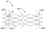
FIG. 8 is an enlarged view of the stent of FIG. 7 of the present disclosure at B
FIG. 9 one embodiment of a stent of the present disclosure
FIG. 10 one embodiment of the present disclosure
Detailed Description
The body has various pipelines including blood vessels, digestive tracts, respiratory tracts, bile ducts, auditory canals and the like; the blood vessels comprise veins, arteries, blood vessels of heart parts, neck blood vessels and the like; the digestive tract includes the esophagus, the intestine, etc. In the prior art, the pipeline is dredged by implanting the stent, and some stents can also be used for therapy in the pipeline when supporting the pipeline.
The alimentary tract includes the esophagus. Clinically, esophageal stenosis is a common symptom of digestive system diseases, and comprises two forms of benign esophageal stenosis (for example, stenosis after chemical erosive burn, congenital stenosis of esophagus and the like) and local tissue hyperplasia of esophagus caused by malignant esophageal cancer. Esophageal stenosis can cause esophageal obstruction in patients, leading to dysphagia and even respiratory failure. The esophageal stent implantation can provide enough physical support for the part which is narrowed due to the pathological changes, and keep the cavity channel smooth so as to smoothly enter water and eat food.
In the prior art, when the irregular shape of the inner wall lesion is adaptively set, the following method is mostly adopted.
For example, in the first mode, the larger meshes are adopted, and can accommodate the lesion part, so that the stress of the stent on the inner wall is reduced. Although this method can reduce the stress on the inner wall of the stent, the larger mesh arrangement makes the lesion on the inner wall easily penetrate through the mesh, thereby stimulating the hyperplasia of the lesion.
In order to prevent the pathological hyperplasia, electrostatic spinning technology or drug coating technology is also commonly adopted in the field, and a drug coating is arranged on the outer side of the stent. Obviously, the coating can be arranged to inhibit the hyperplasia of the lesion by using the medicament in the coating, but the double-layer stent has the advantages of more complex and higher cost in manufacturing. Such stent inner layers are typically made of a metallic material to provide the supporting force. The degradation period of the metal stent is different from that of the outer drug coating, so that the design of the stent is more difficult.
The second method comprises the following steps: when the support is woven, fixing points of the support silk threads are arranged at intervals, and the support can adapt to the irregular pressure of the inner wall to the inner side at the position where the support silk threads are not connected, so that the protruding stress of the support to the inner wall is reduced. However, this weaving method is complicated and the manufacturing cost is high. Moreover, the stent manufactured by the weaving method has uneven point transition of the stent supporting force, too small supporting force at the position where the wires are not connected and too large supporting force at the position where the wires are connected.
Accordingly, the present disclosure provides a bracket that overcomes the deficiencies in the prior art.
The first embodiment is as follows:
as shown in fig. 1, the present disclosure discloses a stent 10 that may be used to support a body lumen such as an esophagus, a blood vessel, an airway, an ear canal, or the like. The stent is composed of a plurality of tube elements, each of which is formed by bending a wire, the plurality of tube elements constituting, in combination with each other, a hollow tube capable of allowing a fluid to flow from one end to the other end; the fluid may be blood, or food flowing in the esophagus or food being digested, or air flowing in the hollow tube. Fig. 1 shows a schematic view of the stent 10 deployed flat. The plurality of pipe elements comprises a first pipe element comprising at least a first filament 1 (101, 102, 103), the first filament comprising a first degradable material; the plurality of pipe elements further comprises a second pipe element comprising at least a second filament 2 (201, 202, 203), the second filament comprising a second degradable material; and the stent is manufactured by the methods of weaving the first silk thread and the second silk thread, 3D printing and the like.
As shown in FIG. 4, the first pipe element has a first diameter D1 and the second pipe element has a diameter D2, and the first diameter D1 of the first pipe element compresses to a first compressed diameter D12 and the first diameter D2 of the second pipe element compresses to a second compressed diameter D22 when subjected to the same radial compression force F. For the first pipe element, the diametral compression dimension is 2S1; for the second pipe element, the compression dimension is 2S2.
A first deformation ratio λ 1=2s1/D1 of the first pipe element;
a second deformation ratio λ 2=2s2/D2 of the second pipe element;
wherein the first deformation ratio λ 1 is different from the second deformation ratio λ 2.
Alternatively, D1 is the same as D2, or D1 is slightly smaller in diameter than D2.
Advantageously, the first tube member provides greater support than the second tube when the first tube member has a lower deformation rate than the second tube member, i.e., when the stent is compressed when the stent is implanted in a body lumen. The inner walls of blood vessels and esophagus have irregular shapes and different flexibilities due to pathological changes. Due to the adoption of materials with different supporting forces, the stent has slow transition supporting force change while having supporting forces in the circumferential direction and the axial direction, and prevents hard support from puncturing the lesion of the inner wall. I.e. the wires 101, 102, 103 of the pipe element 1 are able to provide a greater supporting force; the wires 201, 202, 203 of the tube element provide a certain flexibility. The two silk threads with different supporting forces are woven together to form the stent, and the interweaving points of the two silk threads are uniformly distributed, so that the mechanical property of the stent is more stable and predictable.
Optionally, the ratio of the deformation ratio λ 1 of the first pipe element diameter D1 to the deformation ratio λ 2 of the second pipe element diameter D2 ranges from 0.7< λ 1: λ 2 <0.9. Within this range of deformation ratios, the overall performance of the stent is optimized, i.e. both a greater support force of the first tube element can be exerted and the flexibility of the second tube element can be fully utilized. The first pipe element has a compressibility less than the second pipe element and a tensile strength greater than the tensile strength of the second pipe element.
Beneficially, disclosed herein is a single layer stent, simple to manufacture; and the materials adopted by the stent are all polymer materials and do not contain metal materials, so that the control of the degradation period of the stent is easier.
Alternatively, for example, as shown in fig. 2, the first tube element is disposed on the inside of the stent and the second tube element is disposed on the outside of the stent. When the bracket is subjected to the pressure of the lumen, the second pipe element transmits the pressure to the first pipe element, so that the deformation of the whole bracket is more uniform. As shown in fig. 3, the threads L1 and L4 of the first tubular element enclose a quadrilateral with the threads L2 and L3 of the second tubular element and form four vertices, D1, D2, D3, D4. Four vertex uniform sections. The pressure of the cavity to the second wire is evenly transmitted to the first wire. As shown in fig. 4, the second wire of the second tube element, when subjected to lumen pressure, can form a diameter that fits inside the first tube element, the second tube element forming a virtual diameter D22 that is smaller than the diameter D12 of the first tube element after compression.
Advantageously, in the stent manufactured by weaving or 3D printing or other methods in the present disclosure, the connection points or force bearing points between the threads are evenly distributed, so that the stent support force changes more softly.
Example two:
the first degradable material comprises: one or more of polycaprolactone, polyanhydride, tyrosine polycarbonate, polyglycolide-lactide, and polydioxanone. The hardness of the degradable material is high, and a large supporting force can be provided.
Optionally, the tensile strength of the first degradable material is 300-500MPa.
Optionally, the first degradable material is polydioxanone, and the tensile strength is 440-480MPa.
The second degradable material comprises: polylactic acid-glycolic acid copolymer, polylactic acid, polyglycolic acid, and copolymers of polylactic acid and polyglycolic acid. The material is relatively low in hardness and can provide flexibility to the stent to accommodate and bear the inner wall diseased protruding portions.
Optionally, the tensile strength of the first degradable material is 40-100MPa.
Optionally, the first degradable material is polylactic acid and polyglycolic acid, and the tensile strength is 45-90MPa.
Advantageously, the two polymer materials are used simultaneously, so that the controlled degradation time is guaranteed. A self-expanding polymeric material.
Example three:
as shown in fig. 5 and 6, the second degradable material includes one or more of the following materials: polylactic acid-glycolic acid copolymer, polylactic acid, polyglycolic acid, and copolymers of polylactic acid and polyglycolic acid. The second filament 2 includes a second filament body 2110, and a plurality of recesses are formed in the second filament body, and drug particles 2111 are embedded in the recesses.
Optionally, the second thread further comprises one or more of paclitaxel, paclitaxel derivatives, taxane, taxol, docetaxel, epothilone, nocodazole, cabazitaxel, combretastatin, docetaxel trihydrate, vinorelbine tartrate, combretastatin disodium phosphate, albendazole, triclabendazole, vinflunine tartrate, rapamycin, and rapamycin derivatives.
Advantageously, by incorporating a drug, such as paclitaxel, into the polylactic acid-glycolic acid copolymer, the stent itself is provided with the drug, reducing the process flow compared to a stent graft.
Meanwhile, the polylactic acid-glycolic acid copolymer and the paclitaxel are mixed and processed into the silk thread, the diameter of the silk thread is uniform, and the dosage of the paclitaxel contained in the silk thread is also uniform, so that the dosage of the paclitaxel in the stent can be calculated only by measuring how many silk threads are used when the stent is processed. However, the process method of adding paclitaxel to the stent in a film covering manner has the disadvantages that the film covering technology is not uniform and the film covering thickness is not consistent due to immaturity of the film covering technology. The dosage inaccuracy is calculated by measuring the thickness of the coating film. Therefore, the scheme disclosed by the invention can calculate the medicine carrying amount more accurately and conveniently.
Example four:
the second silk thread comprises polylactic acid-glycolic acid copolymer and paclitaxel, wherein the content of the paclitaxel is 5.19x10 2 μg/mm 3 -1.6x10 4 μg/mm 3 。
The beneficial results are: the proportion of paclitaxel can be adjusted. Due to the fact that the proportion of the paclitaxel is different, the diameter of the second silk thread can be adjusted according to the proportion of the paclitaxel, and under the condition that the amount of the paclitaxel is large, the size of the second silk thread is increased, and therefore the degradation period is prolonged.
Example five:
the diameter of the first wire is: 0.1-0.5mm;
the diameter of the second wire is: 0.1-0.5mm.
Alternative a):
the first degradable material of the first filament comprises polydioxanone, with a tensile strength of 440MPa;
the second degradable material of the second thread comprises a copolymer of polylactic acid and polyglycolic acid, having a tensile strength of 45MPa.
The diameter of the first wire is 0.1mm; the diameter of the second wire is 0.3mm;
alternative b):
the first degradable material of the first filament comprises polydioxanone, having a tensile strength of 450MPa;
the second degradable material of the second filament comprises a copolymer of polylactic acid and polyglycolic acid, having a tensile strength of 40MPa.
The diameter of the first wire is 0.2mm; the diameter of the second wire is 0.2mm;
alternative c):
the first degradable material of the first filament comprises polydioxanone, with a tensile strength of 480MPa;
the second degradable material of the second thread comprises a copolymer of polylactic acid and polyglycolic acid, having a tensile strength of 45MPa.
The diameter of the first wire is 0.3mm; the diameter of the second wire is 0.5mm;
advantageously, in the case where greater support is required, the diameter of the first wire can be chosen to be larger; where a softer stent is desired, the diameter of the second wire may be selected to be smaller; meanwhile, the supporting force can be realized by adjusting the weaving density of the first threads and the weaving density of the second threads.
Example six:
the first and second wires have contact points through which the first and second wires are connected.
Advantageously, the two wires are connected by contact points, making the stent one piece. The rigidity and flexibility of the stent have continuity, and the stress of the stent when the stent is implanted into a cavity is reduced.
Example seven:
the contact point further comprises a connecting element, which is made of a degradable material.
And (4) point bonding the liquid at the contact point. The two silk threads can be connected and fixed through the bonding liquid by adopting methods such as ultraviolet curing and the like.
Advantageously, the connection of the tube elements of the stent is made stronger by the connecting elements.
Example eight:
as shown in fig. 1, the first tube element includes a plurality of first threads, the second tube element includes a plurality of second threads, in a tiled view of the stent, the first threads are parallel to each other, the second threads are parallel to each other, two adjacent first threads intersect with each other to form a quadrangle, and four vertexes of the quadrangle are formed by the intersection of the first threads and the second threads. As shown in fig. 2, in a radial cross-sectional view of the stent, the first wires are disposed on one side close to the central line of the stent shaft, and the second wires are disposed on the other side far from the central line of the stent shaft. The stent is manufactured by 3D printing, i.e. first printing a first thread to form a first tube element and then printing a second thread to form a second tube element, or weaving, first weaving a first thread to form a first tube element and then weaving a second thread to form a second tube element.
Advantageously, the first wire has a high tensile strength and the second wire has a low tensile strength, and placement of the first wire inside the stent may provide better support for the lumen with greater tensile strength of the first tubular element. And the first wire and the second wire form an intersection point, and when the second wire is bent inwards due to the pressure of the lumen, the second wire transmits the received pressure to the first wire through the intersection point.
The first tube element comprises a number of first filaments and the second tube element comprises a number of second filaments, and the number of first filaments is different from the number of second filaments. When the support force is required to be higher, the proportion of the first wires to the second wires can be selected to be 1: 1; when the stent is required to be softer, the number of the second silk threads is more than that of the first silk threads, for example, the ratio of the first silk threads to the second silk threads is 1: 2, namely, one first silk thread is clamped between two second silk threads; it is also possible to select the ratio of the first and second threads to be 1: 5, i.e. two second threads on each side of the first thread.
The beneficial results are: the supporting force softness of the bracket is adjusted by adjusting the proportion of the silk threads.
Example nine:
the connecting portion further includes a magnesium alloy. The magnesium alloy can be selected from magnesium-aluminum alloy, magnesium-manganese alloy, magnesium-zinc alloy, magnesium-rare earth alloy, magnesium-lithium alloy, magnesium-calcium alloy and magnesium-silver alloy, and the connecting part material of the magnesium alloy, the degradable high polymer material and the magnesium alloy are also selected. The bracket can be scanned by scanning equipment in the bracket implantation process or after the bracket is implanted, so that the magnesium-aluminum alloy is identified, and the bracket is positioned.
Example ten:
as shown in fig. 10, the stent 61 is composed of a first wire 601 and a second wire 602, and further includes a third pipe element 62 and a fourth pipe element 63, the material of which each includes a magnesium alloy. The third tube element and the fourth tube element are respectively arranged at one end of the stent, and the length and the position information of the stent can be identified through scanning equipment during or after the stent is implanted.
The bracket also includes a connecting portion 64. Connecting portion 64 is connected to third and fourth pipe elements 62, 62 and connecting portion 64 is connected to the first and second wires.
Advantageously, the bends in the third and fourth tube elements may enable a relatively good compression of the stent; since the third and fourth pipe elements are composed of a magnesium alloy having a larger supporting force, a larger supporting force can be provided.
Example eleven:
as shown in fig. 7 and 8, the stent 41 includes first pipe elements 402, 403 and a second pipe element 401. The first tube element is braided from first filaments 4021, 4031; the second tube element is woven from second filaments 4011. The first tube element is located at an end of the stent and the second tube element is located in a middle of the stent.
Advantageously, the first wires with higher strength are adopted at the two ends, so that the bracket provides larger supporting force during positioning in the pipeline.
Optionally, as shown in fig. 8, the first filaments 4021 are integrally woven with the second filaments 4011 by weaving.
The beneficial is that the connection is uniformly realized in a weaving mode, and the integrity is more complete.
Example twelve:
as shown in fig. 9, embodiment twelve is an alternative to embodiment eleven. Wherein the first pipe element opening is in an expanded configuration. Advantageously, the arrangement enables better retention of the stent at both ends within the duct.
The processing technology of the bracket comprises the following steps:
1. preformed polylactic acid-glycolic acid copolymer-paclitaxel solution
101: preparing an emulsion: adding 100mg of polylactic acid-glycolic acid copolymer into 2.0ml of dichloromethane solution to prepare emulsion solution;
102: paclitaxel solution: adding paclitaxel, dissolving with dichloromethane solution of polylactic acid-glycolic acid copolymer, and ultrasonic processing for 3-5 min;
103: preparing a polyvinyl alcohol solution: the paclitaxel solution was added dropwise to 30ml of polyvinyl alcohol (PVA) aqueous solution, stirred at high speed, and then diluted with water until the PVA concentration was 2%. Stirring the polyvinyl alcohol solution at a low speed of 500r/min for 2 hours;
104: preparing polylactic acid-glycolic acid copolymer-paclitaxel stock solution: treating the prepared polyvinyl alcohol solution, filtering out an external water phase in the polylactic acid-glycolic acid copolymer-paclitaxel solution, and repeatedly centrifuging and washing the residual solution. Until the polylactic acid-glycolic acid copolymer-paclitaxel stock solution does not contain dichloromethane and PVA, and the polylactic acid-glycolic acid copolymer-paclitaxel stock solution is obtained for standby.
2. Preparing a polylactic acid-glycolic acid copolymer wire with a highly porous structure:
the parameters are: 5L/95G, 10L/90G, 15L/85G, 20L/80G, 25L/75G, 30L/70G, 35L/65G, 40L/60G, 45L/55G, 50L/50G, 55L/45G, 60L/40G, 65L/35G, 70L/30G, 75L/25G, 80L/20G, 85L/15G, 90L/10G and 95L/5G, and the materials of the polylactic acid-glycolic acid copolymer with the particle size range of 200-250 mu m are screened out, and then NaCI particles with the same particle size range as the materials are mixed according to the mass ratio of 1 to (16-20) respectively to obtain the polylactic acid-glycolic acid copolymer and the sodium chloride mixture. The mixture of the polylactic acid-glycolic acid copolymer and the sodium chloride is stirred for 1 hour at the temperature of 25 ℃ in a low-speed stirrer at the speed of 60r/min, so that the particles are uniformly mixed. And then putting the mixture into an extruder, extruding a 0.1-0.5mm diameter polylactic acid-glycolic acid copolymer and sodium chloride mixed filament at the temperature of 180-220 ℃ and under the pressure of 5-7MPa, repeatedly soaking the mixed filament in double distilled water, and obtaining a highly porous polylactic acid-glycolic acid copolymer filament body after completely removing NaCI, wherein the polylactic acid-glycolic acid copolymer filament body is dried to constant weight under the condition of reduced pressure for later use.
A freeze-drying procedure: and (3) immersing the polylactic acid-glycolic acid copolymer wire body with a highly porous structure into a polylactic acid-glycolic acid copolymer-paclitaxel stock solution, and performing freeze-drying treatment to obtain the polylactic acid-glycolic acid copolymer-paclitaxel silk thread.
Alternatively, the highly porous structural polylactic acid-glycolic acid copolymer is weighed and the weight W1 is recorded. And (3) immersing the polylactic acid-glycolic acid copolymer wire with a highly porous structure into a polylactic acid-glycolic acid copolymer-paclitaxel stock solution, and recording the weight W2 of the polylactic acid-glycolic acid copolymer wire after freeze-drying treatment. The weight difference before and after lyophilization, i.e. W = W2-W1, is the weight of the polylactic acid-glycolic acid copolymer-paclitaxel stock solution embedded in the polylactic acid-glycolic acid copolymer filament. The amount of the paclitaxel carried in the polylactic acid-glycolic acid copolymer silk can be calculated according to the amount of the paclitaxel contained in the polylactic acid-glycolic acid copolymer-paclitaxel stock solution.
Optionally, after the polylactic acid-glycolic acid copolymer wire with a highly porous structure is immersed in the polylactic acid-glycolic acid copolymer-paclitaxel stock solution, a 2.5% concentration mannitol aqueous solution is added, and the mixed solution is freeze-dried. To obtain the polylactic acid-glycolic acid copolymer-paclitaxel silk thread.
Advantageously, mannitol is a lyoprotectant, maintaining the drug-loaded stability of the loaded microspheres, which may be present in the wire.
Alternatively, the paclitaxel content is 5.19x10 2 μg/mm 3 -1.6x10 4 μg/mm 3 That is, each cubic millimeter of polylactic acid-glycolic acid copolymer and paclitaxel silk contains paclitaxel 5.19x10 2 μg-1.6x10 4 μg。
The polylactic acid-glycolic acid copolymer-paclitaxel silk thread is subjected to surface cleaning and is formed into a dish.
4. Preparing a bracket:
the polylactic acid-glycolic acid copolymer-paclitaxel silk thread and the polydioxanone silk thread are prepared into the stent by methods of weaving, 3D printing and the like.
Although the present invention has been described with reference to particular embodiments, it will be understood by those skilled in the art that various changes in form and details may be made therein without departing from the spirit and scope of the invention as defined by the appended claims.
Claims (8)
1. A stent comprising a plurality of tube elements, each of the tube elements comprising a wire; the method is characterized in that:
the plurality of pipe elements comprises a first pipe element comprising at least a first filament comprising a first degradable polymer material;
the plurality of pipe elements further comprises a second pipe element comprising at least a second filament comprising a second degradable polymer material;
the first pipe element having a first diameter and the second pipe element having a second diameter, the first diameter of the first pipe element having a first deformation ratio less than a second deformation ratio of the second diameter of the second pipe element under the same radial compressive force;
the second pipe element comprises a plurality of second silk threads, in a tiled drawing of the bracket, the first silk threads are parallel to each other, the second silk threads are parallel to each other, two adjacent first silk threads and two adjacent second silk threads are intersected respectively to form a quadrangle, four vertexes of the quadrangle are formed by intersecting the first silk threads and the second silk threads, in a radial sectional drawing of the bracket, the first silk threads are arranged on one side close to the central line of the bracket shaft, and the second silk threads are arranged on the other side far away from the central line of the bracket shaft;
the stent, in an unstressed condition, having a first diameter, the first pipe element has a second diameter,
in the event that the stent is subjected to a radially compressive force, the first tube element has a deformed first deformed diameter and the wire segments of the second wire of the second tube element constitute a second deformed diameter that is smaller than the first deformed diameter.
2. The bracket of claim 1, wherein: a ratio of a first deformation ratio of a first diameter of the first pipe element to a second deformation ratio of a second diameter of the second pipe element is in a range of 0.7< first deformation ratio: the second deformation ratio is <0.9.
3. A support according to claim 1 or 2, wherein: the first degradable polymer material comprises one or more of polycaprolactone, polyanhydride, tyrosine polycarbonate, polyglycolide-lactide and polydioxanone;
the second degradable polymeric material comprises one or more of the following materials: polylactic acid-glycolic acid copolymer, polylactic acid, polyglycolic acid.
4. The mount of claim 3, wherein: the second filament further comprises one or more of paclitaxel, paclitaxel derivatives, epothilones, nocodazole, combretastatin, vinorelbine tartrate, combretastatin disodium phosphate, albendazole, triclabendazole, vinflunine tartrate, rapamycin, and rapamycin derivatives.
5. The bracket of claim 4, wherein:
the second filament comprises a filament body comprised of the second degradable polymer material, the filament body comprising a plurality of cavities;
the second wire further comprises a plurality of microparticles embedded in the plurality of cavities;
the microparticles comprise one or more of paclitaxel, paclitaxel derivatives, epothilone, nocodazole, combretastatin, vinorelbine tartrate, combretastatin disodium phosphate, albendazole, triclabendazole, vinflunine tartrate, rapamycin, and rapamycin derivatives.
6. The bracket of claim 5, wherein: the second silk thread comprises polylactic acid-glycolic acid copolymer and paclitaxel, wherein the content of the paclitaxel is 5.19x10 2 μg/mm 3 -1.6x10 4 μg/mm 3 That is, each cubic millimeter of polylactic acid-glycolic acid copolymer and paclitaxel silk contains paclitaxel 5.19x10 2 μg-1.6x10 4 μg。
7. The bracket of claim 6, wherein: the first pipe element is located inside the second pipe element;
the tensile strength of the first silk thread is 300-500MPa, and the diameter of the first silk thread is 0.1-0.5mm;
the tensile strength of the second silk thread is 40-100MPa, and the diameter of the first silk thread is 0.1-0.5mm.
8. The stent of claim 7, further comprising third and fourth tube elements, the material of the third and fourth tube elements comprising a degradable metal comprising one of magnesium aluminum alloy, magnesium manganese alloy, magnesium zinc alloy, magnesium rare earth alloy, magnesium lithium alloy, magnesium calcium alloy, magnesium silver alloy, the third tube element disposed at one end of the stent, the fourth tube element at the other end of the stent;
the stent further comprises a stent connecting portion connecting the third and fourth tube elements;
the bracket connection portion includes a bent portion, and the bracket connection portion is connected with the first pipe element and the second pipe element through connection points, respectively.
Priority Applications (1)
| Application Number | Priority Date | Filing Date | Title |
|---|---|---|---|
| CN202111619041.5A CN114259609B (en) | 2021-12-28 | 2021-12-28 | Support frame |
Applications Claiming Priority (1)
| Application Number | Priority Date | Filing Date | Title |
|---|---|---|---|
| CN202111619041.5A CN114259609B (en) | 2021-12-28 | 2021-12-28 | Support frame |
Publications (2)
| Publication Number | Publication Date |
|---|---|
| CN114259609A CN114259609A (en) | 2022-04-01 |
| CN114259609B true CN114259609B (en) | 2023-02-28 |
Family
ID=80830910
Family Applications (1)
| Application Number | Title | Priority Date | Filing Date |
|---|---|---|---|
| CN202111619041.5A Active CN114259609B (en) | 2021-12-28 | 2021-12-28 | Support frame |
Country Status (1)
| Country | Link |
|---|---|
| CN (1) | CN114259609B (en) |
Families Citing this family (1)
| Publication number | Priority date | Publication date | Assignee | Title |
|---|---|---|---|---|
| CN117982740B (en) * | 2024-04-07 | 2024-07-12 | 四川国纳科技有限公司 | Absorbable biomedical polymer material, ligature clip and preparation method |
Citations (12)
| Publication number | Priority date | Publication date | Assignee | Title |
|---|---|---|---|---|
| CN1961977A (en) * | 2006-11-16 | 2007-05-16 | 沈阳 | Degradable radioactive biliary stent and method for producing the same |
| CN101472536A (en) * | 2006-05-24 | 2009-07-01 | 切斯纳特医学技术公司 | Flexible vascular occlusion device |
| CN101496916A (en) * | 2009-02-24 | 2009-08-05 | 重庆大学 | Nano coating combined with micropore surface method for modifying endovascular stent |
| CN102908216A (en) * | 2012-10-30 | 2013-02-06 | 东南大学 | Biodegradable medical human body cavity channel inner bracket and preparation method thereof |
| CN103083120A (en) * | 2011-10-28 | 2013-05-08 | 宛新建 | Biodegradable polymer knitted support capable of preventing bile duct benign and malignant stricture and manufacture method thereof |
| EP2752173A1 (en) * | 2010-01-30 | 2014-07-09 | Abbott Cardiovascular Systems, Inc. | Crush recoverable polymer stents |
| JP2015036107A (en) * | 2013-08-16 | 2015-02-23 | 福田 敏男 | Intravascular treatment hybrid stent with similarity structure |
| CN104511058A (en) * | 2014-12-29 | 2015-04-15 | 复旦大学 | Fully bio-absorbable polymer stent and production method thereof |
| CN107206122A (en) * | 2015-02-13 | 2017-09-26 | W.L.戈尔及同仁股份有限公司 | Coherent single-layer high-strength synthetic polymer composites for artificial valves |
| CN111212618A (en) * | 2017-08-14 | 2020-05-29 | 波士顿科学国际有限公司 | medical stent |
| CN112399832A (en) * | 2018-06-08 | 2021-02-23 | 埃夫莫拉尔医疗有限公司 | Absorbable endovascular device that shortens when expanded, creating space for vascular motion |
| CN113040982A (en) * | 2021-03-03 | 2021-06-29 | 中山大学 | Bionic fiber ring stent and preparation method thereof |
-
2021
- 2021-12-28 CN CN202111619041.5A patent/CN114259609B/en active Active
Patent Citations (13)
| Publication number | Priority date | Publication date | Assignee | Title |
|---|---|---|---|---|
| CN101472536A (en) * | 2006-05-24 | 2009-07-01 | 切斯纳特医学技术公司 | Flexible vascular occlusion device |
| CN103169522A (en) * | 2006-05-24 | 2013-06-26 | 泰科保健集团有限合伙公司 | Flexible vascular occluding device |
| CN1961977A (en) * | 2006-11-16 | 2007-05-16 | 沈阳 | Degradable radioactive biliary stent and method for producing the same |
| CN101496916A (en) * | 2009-02-24 | 2009-08-05 | 重庆大学 | Nano coating combined with micropore surface method for modifying endovascular stent |
| EP2752173A1 (en) * | 2010-01-30 | 2014-07-09 | Abbott Cardiovascular Systems, Inc. | Crush recoverable polymer stents |
| CN103083120A (en) * | 2011-10-28 | 2013-05-08 | 宛新建 | Biodegradable polymer knitted support capable of preventing bile duct benign and malignant stricture and manufacture method thereof |
| CN102908216A (en) * | 2012-10-30 | 2013-02-06 | 东南大学 | Biodegradable medical human body cavity channel inner bracket and preparation method thereof |
| JP2015036107A (en) * | 2013-08-16 | 2015-02-23 | 福田 敏男 | Intravascular treatment hybrid stent with similarity structure |
| CN104511058A (en) * | 2014-12-29 | 2015-04-15 | 复旦大学 | Fully bio-absorbable polymer stent and production method thereof |
| CN107206122A (en) * | 2015-02-13 | 2017-09-26 | W.L.戈尔及同仁股份有限公司 | Coherent single-layer high-strength synthetic polymer composites for artificial valves |
| CN111212618A (en) * | 2017-08-14 | 2020-05-29 | 波士顿科学国际有限公司 | medical stent |
| CN112399832A (en) * | 2018-06-08 | 2021-02-23 | 埃夫莫拉尔医疗有限公司 | Absorbable endovascular device that shortens when expanded, creating space for vascular motion |
| CN113040982A (en) * | 2021-03-03 | 2021-06-29 | 中山大学 | Bionic fiber ring stent and preparation method thereof |
Non-Patent Citations (7)
| Title |
|---|
| Additive manufacturing of patient-customizable scaffolds for tubular tissue using the melt-drawing method;Tan YJ等;《Materials》;20161130;第9卷(第11期);1-12 * |
| Deformation and damage upon stretching of degradable polymers(PLA AND PCL));F.Rezgui等;《Polymer》;20050711;第46卷(第18期);7370-7385 * |
| Rapid fabrication of a cell-seeded collagen gel-based tubular construct that withstands arterial pressure;Tuan-Mu HY等;《Annals of biomedical engineering》;20161130;第44卷(第11期);3384-3397 * |
| 双重可控式编织自增强型可降解血管支架的设计制备及构效关系;赵帆;《中国优秀博士学位论文全文数据库》;20200424;全文 * |
| 复合纺织血管支架物理力学性能研究;薛雯;《中国优秀博士学位论文全文数据库》;20200930;全文 * |
| 生物可降解胆管覆膜支架的制备及其压缩性能数值模拟;刘延辉;《中国优秀硕士学位论文全文数据库》;20170515;全文 * |
| 编织型可降解输尿管支架管的力学性能研究;李文超等;《产业用纺织品》;20140825;第32卷(第8期);13-17 * |
Also Published As
| Publication number | Publication date |
|---|---|
| CN114259609A (en) | 2022-04-01 |
Similar Documents
| Publication | Publication Date | Title |
|---|---|---|
| JP6513187B2 (en) | Composite lumen body having a reinforced woven body and a matrix | |
| JP6300732B2 (en) | Medical device coated with rotating span material and method of manufacturing the same | |
| CN1261084C (en) | Wire for blood vessel stent and blood vessel stent using the same | |
| EP3369400B1 (en) | Lumen woven support | |
| US4880002A (en) | Stretchable porous sutures | |
| CN103142335B (en) | A kind of thermoplastic degradable fiber woven stent and preparation method thereof | |
| CN104382671A (en) | Degradable human body stent capable of effectively preventing transposition and reducing hyperplasia and manufacturing method | |
| CN104720941A (en) | Vessel stent and production method thereof | |
| KR20060028695A (en) | Polymer stents and preparation method thereof | |
| JP2022079625A (en) | Biodegradation controlled medical device | |
| US10350051B2 (en) | Orthotopic artificial bladder endoprosthesis | |
| JP2008253297A (en) | Medical tube | |
| Wang et al. | In vitro degradation behaviours of PDO monofilament and its intravascular stents with braided structure | |
| CN114259609B (en) | Support frame | |
| CN108452383A (en) | A kind of preparation method and application of 3D printing artificial blood vessel | |
| CN101559011B (en) | Drug release tubular support provided with internal supporting wings | |
| JP2018007802A (en) | Lumen stent and manufacturing method thereof | |
| CN114259607B (en) | Preparation method of stent | |
| CN204169954U (en) | A kind of degradable human body alimentary canal support that effectively can prevent displacement, reduce hypertrophy | |
| CN214679116U (en) | Ureter bracket | |
| CN119318550A (en) | Tectorial membrane support | |
| EP2747800A1 (en) | Self-expandable biodegradable stent made of clad radiopaque fibers covered with biodegradable elastic foil and therapeutic agent and method of preparation thereof | |
| US20230029984A1 (en) | Coronary covered stent | |
| CN114522003B (en) | Ureteral stent and preparation method thereof | |
| CN120827647A (en) | A 4D printed esophageal stent and its preparation method |
Legal Events
| Date | Code | Title | Description |
|---|---|---|---|
| PB01 | Publication | ||
| PB01 | Publication | ||
| SE01 | Entry into force of request for substantive examination | ||
| SE01 | Entry into force of request for substantive examination | ||
| TA01 | Transfer of patent application right | ||
| TA01 | Transfer of patent application right |
Effective date of registration: 20221124 Address after: 101-22, Floor 4, Building 9, Yard 55, Zique Road, Haidian District, Beijing 100095 Applicant after: Enpuyu (Beijing) Technology Co.,Ltd. Address before: 100026 Room 303, Unit 1, Building 2, Shuiduizi East Road, Chaoyang District, Beijing Applicant before: Yu Hang Applicant before: Shen Yang Applicant before: Qu Duan Applicant before: Shi Meng |
|
| GR01 | Patent grant | ||
| GR01 | Patent grant |