CN114252022B - Optical fiber multi-dimensional monitoring method and device based on GNSS signals - Google Patents
Optical fiber multi-dimensional monitoring method and device based on GNSS signals Download PDFInfo
- Publication number
- CN114252022B CN114252022B CN202111573260.4A CN202111573260A CN114252022B CN 114252022 B CN114252022 B CN 114252022B CN 202111573260 A CN202111573260 A CN 202111573260A CN 114252022 B CN114252022 B CN 114252022B
- Authority
- CN
- China
- Prior art keywords
- signal
- optical fiber
- gnss
- monitoring
- information
- Prior art date
- Legal status (The legal status is an assumption and is not a legal conclusion. Google has not performed a legal analysis and makes no representation as to the accuracy of the status listed.)
- Active
Links
Images


Classifications
-
- G—PHYSICS
- G01—MEASURING; TESTING
- G01B—MEASURING LENGTH, THICKNESS OR SIMILAR LINEAR DIMENSIONS; MEASURING ANGLES; MEASURING AREAS; MEASURING IRREGULARITIES OF SURFACES OR CONTOURS
- G01B11/00—Measuring arrangements characterised by the use of optical techniques
- G01B11/24—Measuring arrangements characterised by the use of optical techniques for measuring contours or curvatures
-
- G—PHYSICS
- G01—MEASURING; TESTING
- G01B—MEASURING LENGTH, THICKNESS OR SIMILAR LINEAR DIMENSIONS; MEASURING ANGLES; MEASURING AREAS; MEASURING IRREGULARITIES OF SURFACES OR CONTOURS
- G01B21/00—Measuring arrangements or details thereof, where the measuring technique is not covered by the other groups of this subclass, unspecified or not relevant
- G01B21/20—Measuring arrangements or details thereof, where the measuring technique is not covered by the other groups of this subclass, unspecified or not relevant for measuring contours or curvatures, e.g. determining profile
-
- G—PHYSICS
- G01—MEASURING; TESTING
- G01D—MEASURING NOT SPECIALLY ADAPTED FOR A SPECIFIC VARIABLE; ARRANGEMENTS FOR MEASURING TWO OR MORE VARIABLES NOT COVERED IN A SINGLE OTHER SUBCLASS; TARIFF METERING APPARATUS; MEASURING OR TESTING NOT OTHERWISE PROVIDED FOR
- G01D21/00—Measuring or testing not otherwise provided for
- G01D21/02—Measuring two or more variables by means not covered by a single other subclass
Landscapes
- Physics & Mathematics (AREA)
- General Physics & Mathematics (AREA)
- Optical Transform (AREA)
- Length Measuring Devices By Optical Means (AREA)
Abstract
本发明公开了一种基于GNSS信号的光纤多维监测方法。在远端,通过设置于监测点的至少两根GNSS天线接收GNSS信号并将所接收的GNSS信号分别调制到光域,然后将光载GNSS信号通过传输光纤传输至近端的接收机;在近端,通过向传输光纤发射宽带光探测信号并对光纤沿线的散射信号以及光纤端面的反射光信号进行处理得到传输光纤沿线的分布式监测结果以及传输光纤的长度信息,然后基于所得到的光纤长度信息获得硬件延时信息,最后利用硬件延时信息和载波相位单差模型得到监测点的三维监测信息。本发明还公开了一种基于GNSS信号的光纤多维监测装置。相比现有技术,本发明可同时实现对重点监测部位的高精度三维监测以及对应变、振动、温度等信息的大范围分布式监测。
The invention discloses an optical fiber multi-dimensional monitoring method based on GNSS signals. At the far end, GNSS signals are received by at least two GNSS antennas arranged at the monitoring point and the received GNSS signals are respectively modulated into the optical domain, and then the light-borne GNSS signals are transmitted to the near-end receiver through the transmission fiber; at the near end, By sending a broadband optical detection signal to the transmission fiber and processing the scattered signal along the fiber and the reflected light signal of the fiber end face to obtain the distributed monitoring results along the transmission fiber and the length information of the transmission fiber, and then based on the obtained fiber length information to obtain The hardware delay information, and finally the three-dimensional monitoring information of the monitoring point is obtained by using the hardware delay information and the carrier phase single-difference model. The invention also discloses an optical fiber multi-dimensional monitoring device based on GNSS signals. Compared with the prior art, the present invention can realize high-precision three-dimensional monitoring of key monitoring parts and large-scale distributed monitoring of strain, vibration, temperature and other information at the same time.
Description
技术领域technical field
本发明涉及一种光纤监测方法,尤其涉及一种基于GNSS(Global NavigationSatellite System,全球导航卫星系统)信号的光纤多维监测方法。The invention relates to an optical fiber monitoring method, in particular to an optical fiber multi-dimensional monitoring method based on GNSS (Global Navigation Satellite System, Global Navigation Satellite System) signals.
背景技术Background technique
分布式光纤传感技术作为光纤传感技术中的重要分支,集光信号传输与参量传感于一体,光纤既是传输介质又是传感介质,能实现整个光纤链路的参量连续测量,测量范围极大。在民用领域,桥梁、隧道,搭乘飞机,水坝等的结构安全需要被监测,分布式传感技术是探测这些建筑结构的健康状况的有效手段。石化行业中的易燃易爆、高电压领域缺乏可靠安全监测技术手段,航空发动机、港口装卸设备等重要和大型设备由于结构复杂和工作环境恶劣,也缺乏有效的监测手段,分布式传感可以有效的解决这些需求。在军事领域,光纤系统、传感器设备、电子系统有机整合,需要在指定地点进行物理参数的检测,例如:可以检测温度数据、压力数据、应变数据等,构建故障监测系统、飞行控制系统,还能通过先进技术进行军事装备的损伤评估。As an important branch of optical fiber sensing technology, distributed optical fiber sensing technology integrates optical signal transmission and parameter sensing. Optical fiber is both a transmission medium and a sensing medium, which can realize continuous measurement of parameters of the entire optical fiber link. The measurement range great. In the civil field, the structural safety of bridges, tunnels, airplanes, dams, etc. needs to be monitored, and distributed sensing technology is an effective means to detect the health of these building structures. The flammable, explosive and high-voltage fields in the petrochemical industry lack reliable safety monitoring technology means. Important and large-scale equipment such as aero-engines and port handling equipment also lack effective monitoring methods due to their complex structure and harsh working environment. Distributed sensing can effectively address these needs. In the military field, optical fiber systems, sensor equipment, and electronic systems are organically integrated, and physical parameters need to be detected at designated locations. For example, temperature data, pressure data, and strain data can be detected to build fault monitoring systems and flight control systems. Damage assessment of military equipment through advanced technology.
传统的分布式光纤传感技术多采用光时域反射或光频域反射方法,能够监测光纤中的损耗和断点等,再基于瑞利散射,能够对光纤的应变、振动、温度等进行监测,但其只能实现二维上的监测,对一些需要重点监测的部位无法做到高精度的三维监测,且其存在一些监测范围上的限制。比如在电网铁塔监测中,既需要监测铁塔的三维形变,又需要监测电缆的分布式应力;又如在管道监测中,既需要对管道的温度变化进行监测,又需要对一些重点部位进行三维高精度监测。在这样的情况下,传统的测量方法无法满足需求,就需要新的光纤多维监测方法。Traditional distributed optical fiber sensing technology mostly uses optical time domain reflection or optical frequency domain reflection method, which can monitor the loss and breakpoint in the optical fiber, and then based on Rayleigh scattering, it can monitor the strain, vibration, temperature, etc. of the optical fiber , but it can only achieve two-dimensional monitoring, and it cannot achieve high-precision three-dimensional monitoring for some key monitoring parts, and there are some limitations in the monitoring range. For example, in the monitoring of iron towers in the power grid, it is necessary to monitor the three-dimensional deformation of the iron towers and the distributed stress of cables; Accuracy monitoring. Under such circumstances, the traditional measurement method cannot meet the demand, and a new optical fiber multi-dimensional monitoring method is needed.
发明内容Contents of the invention
本发明所要解决的技术问题在于克服现有技术不足,提供一种基于GNSS信号的光纤多维监测方法,将分布式光纤传感技术与GNSS定位技术有机结合,可同时实现对重点监测部位的高精度三维监测以及对应变、振动、温度等信息的大范围分布式监测。The technical problem to be solved by the present invention is to overcome the deficiencies of the existing technologies, provide a GNSS signal-based optical fiber multi-dimensional monitoring method, organically combine distributed optical fiber sensing technology with GNSS positioning technology, and realize high-precision monitoring of key monitoring parts at the same time Three-dimensional monitoring and large-scale distributed monitoring of strain, vibration, temperature and other information.
本发明具体采用以下技术方案解决上述技术问题:The present invention specifically adopts the following technical solutions to solve the above technical problems:
一种基于GNSS信号的光纤多维监测方法,在远端,通过设置于监测点的至少两根GNSS天线接收GNSS信号并将所接收的GNSS信号分别调制到光域,然后将所生成的光载GNSS信号通过传输光纤传输至近端的接收机;同时,在近端,通过向所述传输光纤发射宽带光探测信号并对光纤沿线的散射信号以及光纤端面的反射光信号进行处理得到所述传输光纤沿线的分布式监测结果以及所述传输光纤的长度信息,然后基于所得到的光纤长度信息获得GNSS天线与近端接收机之间的硬件延时信息,最后利用GNSS天线到接收机之间的硬件延时信息和载波相位单差模型得到监测点的三维监测信息。An optical fiber multi-dimensional monitoring method based on GNSS signals, at the remote end, receives GNSS signals through at least two GNSS antennas arranged at the monitoring point and modulates the received GNSS signals into the optical domain respectively, and then transmits the generated light-borne GNSS The signal is transmitted to the receiver at the near end through the transmission fiber; at the same time, at the near end, by transmitting a broadband optical detection signal to the transmission fiber and processing the scattered signal along the fiber and the reflected light signal at the end face of the fiber to obtain the signal along the transmission fiber Distributed monitoring results and the length information of the transmission fiber, and then based on the obtained fiber length information to obtain the hardware delay information between the GNSS antenna and the near-end receiver, and finally use the hardware delay between the GNSS antenna and the receiver Information and carrier phase single-difference model to obtain three-dimensional monitoring information of monitoring points.
优选地,所述宽带光探测信号为线性调频信号。Preferably, the broadband light detection signal is a chirp signal.
基于同一发明构思还可以得到以下技术方案:The following technical solutions can also be obtained based on the same inventive concept:
一种基于GNSS信号的光纤多维监测装置,包括:An optical fiber multi-dimensional monitoring device based on GNSS signals, comprising:
三维基线测量单元,其设置在远端,用于通过设置于监测点的至少两根GNSS天线接收GNSS信号并将所接收的GNSS信号分别调制到光域;A three-dimensional baseline measurement unit, which is arranged at the far end, is used to receive GNSS signals through at least two GNSS antennas arranged at the monitoring point and modulate the received GNSS signals into the optical domain respectively;
传输光纤,用于将所生成的光载GNSS信号传输至近端的接收机;A transmission fiber for transmitting the generated light-borne GNSS signal to a near-end receiver;
分布式信号与硬件延时信号发射与处理模块,其设置于近端,用于通过向所述传输光纤发射宽带光探测信号并对光纤沿线的散射信号以及光纤端面的反射光信号进行处理得到所述传输光纤沿线的分布式监测结果以及所述传输光纤的长度信息,然后基于所得到的光纤长度信息获得GNSS天线与近端接收机之间的硬件延时信息;Distributed signal and hardware delay signal transmission and processing module, which is arranged at the near end, is used to transmit broadband optical detection signal to the transmission optical fiber and process the scattered signal along the optical fiber and the reflected optical signal on the end face of the optical fiber to obtain the Distributed monitoring results along the transmission optical fiber and the length information of the transmission optical fiber, and then obtain hardware delay information between the GNSS antenna and the near-end receiver based on the obtained optical fiber length information;
三维基线信号处理模块,利用GNSS天线到接收机之间的硬件延时信息和载波相位单差模型得到监测点的三维监测信息。The three-dimensional baseline signal processing module uses the hardware delay information between the GNSS antenna and the receiver and the carrier phase single-difference model to obtain the three-dimensional monitoring information of the monitoring point.
优选地,所述宽带光探测信号为线性调频信号。Preferably, the broadband light detection signal is a chirp signal.
相比现有技术,本发明技术方案具有以下有益效果:Compared with the prior art, the technical solution of the present invention has the following beneficial effects:
本发明技术方案通过将分布式光纤传感技术与GNSS定位技术有机结合,可以同时实现二维分布式监测与重点部位的三维监测,更为重要的是,可以通过两者的信息融合,提升三维监测的精度和监测范围,不仅拓展光纤监测方法的功能并提升监测精度等性能,从而大幅拓宽传感系统的应用场景。The technical scheme of the present invention organically combines the distributed optical fiber sensing technology with the GNSS positioning technology, and can realize two-dimensional distributed monitoring and three-dimensional monitoring of key parts at the same time, and more importantly, can improve the three-dimensional The monitoring accuracy and monitoring range not only expand the functions of the optical fiber monitoring method but also improve the monitoring accuracy and other performances, thereby greatly broadening the application scenarios of the sensing system.
附图说明Description of drawings
图1为本发明光纤多维监测装置的结构原理示意图;Fig. 1 is the schematic diagram of the structural principle of the optical fiber multi-dimensional monitoring device of the present invention;
图2为本发明光纤多维监测装置一个具体实施例的结构示意图。Fig. 2 is a structural schematic diagram of a specific embodiment of the optical fiber multi-dimensional monitoring device of the present invention.
具体实施方式Detailed ways
针对现有技术不足,本发明的解决思路是基于GNSS信号和光纤传输、传感原理,用多路的载波观测值的差分获取GNSS天线间的三维向量,实现重点部位的三维全向监测,同时利用宽带光探测信号获取硬件延时信息和分布式传感信息,并进一步利用硬件延时信息提升三维向量的测量精度。Aiming at the deficiencies of the prior art, the solution idea of the present invention is based on GNSS signals and optical fiber transmission and sensing principles, and obtains the three-dimensional vector between GNSS antennas by using the difference of multi-channel carrier observation values, so as to realize the three-dimensional omnidirectional monitoring of key parts, and at the same time The broadband optical detection signal is used to obtain hardware delay information and distributed sensing information, and the hardware delay information is further used to improve the measurement accuracy of the three-dimensional vector.
本发明所提出的基于GNSS信号的光纤多维监测方法,具体如下:The optical fiber multi-dimensional monitoring method based on GNSS signal proposed by the present invention is as follows:
在远端,通过设置于监测点的至少两根GNSS天线接收GNSS信号并将所接收的GNSS信号分别调制到光域,然后将所生成的光载GNSS信号通过传输光纤传输至近端的接收机;同时,在近端,通过向所述传输光纤发射宽带光探测信号并对光纤沿线的散射信号以及光纤端面的反射光信号进行处理得到所述传输光纤沿线的分布式监测结果以及所述传输光纤的长度信息,然后基于所得到的光纤长度信息获得GNSS天线与近端接收机之间的硬件延时信息,最后利用GNSS天线到接收机之间的硬件延时信息和载波相位单差模型得到监测点的三维监测信息。At the far end, the GNSS signals are received by at least two GNSS antennas arranged at the monitoring point and the received GNSS signals are respectively modulated into the optical domain, and then the generated light-borne GNSS signals are transmitted to the near-end receiver through the transmission fiber; at the same time , at the near end, the distributed monitoring results along the transmission fiber and the length of the transmission fiber are obtained by transmitting a broadband optical detection signal to the transmission fiber and processing the scattered signal along the fiber and the reflected light signal from the end face of the fiber information, and then obtain the hardware delay information between the GNSS antenna and the near-end receiver based on the obtained fiber length information, and finally use the hardware delay information between the GNSS antenna and the receiver and the carrier phase single-difference model to obtain the 3D monitoring information.
本发明所提出的基于GNSS信号的光纤多维监测装置,如图1所示,包括:三维基线测量单元,其设置在远端,用于通过设置于监测点的至少两根GNSS天线接收GNSS信号并将所接收的GNSS信号分别调制到光域;The optical fiber multi-dimensional monitoring device based on GNSS signals proposed by the present invention, as shown in Figure 1, includes: a three-dimensional baseline measurement unit, which is arranged at the far end, for receiving GNSS signals by at least two GNSS antennas arranged at monitoring points and modulate the received GNSS signals into the optical domain respectively;
传输光纤,用于将所生成的光载GNSS信号传输至近端的接收机;A transmission fiber for transmitting the generated light-borne GNSS signal to a near-end receiver;
分布式信号与硬件延时信号发射与处理模块,其设置于近端,用于通过向所述传输光纤发射宽带光探测信号并对光纤沿线的散射信号以及光纤端面的反射光信号进行处理得到所述传输光纤沿线的分布式监测结果以及所述传输光纤的长度信息,然后基于所得到的光纤长度信息获得GNSS天线与近端接收机之间的硬件延时信息;Distributed signal and hardware delay signal transmission and processing module, which is arranged at the near end, is used to transmit broadband optical detection signal to the transmission optical fiber and process the scattered signal along the optical fiber and the reflected optical signal on the end face of the optical fiber to obtain the Distributed monitoring results along the transmission optical fiber and the length information of the transmission optical fiber, and then obtain hardware delay information between the GNSS antenna and the near-end receiver based on the obtained optical fiber length information;
三维基线信号处理模块,利用GNSS天线到接收机之间的硬件延时信息和载波相位单差模型得到监测点的三维监测信息。The three-dimensional baseline signal processing module uses the hardware delay information between the GNSS antenna and the receiver and the carrier phase single-difference model to obtain the three-dimensional monitoring information of the monitoring point.
优选地,所述宽带光探测信号为线性调频信号。Preferably, the broadband light detection signal is a chirp signal.
本发明技术方案可广泛应用于堤坝、桥梁、大楼、供电铁塔、矿井等的结构健康监测,可同时实现对重点监测部位的高精度三维监测以及对应变、振动、温度等信息的大范围分布式监测。为了便于公众理解,下面通过一个具体实施例并结合附图来对本发明的技术方案进行详细说明:The technical scheme of the invention can be widely applied to structural health monitoring of dams, bridges, buildings, power supply towers, mines, etc., and can simultaneously realize high-precision three-dimensional monitoring of key monitoring parts and large-scale distribution of strain, vibration, temperature and other information monitor. In order to facilitate the public's understanding, the technical solution of the present invention will be described in detail below through a specific embodiment in conjunction with the accompanying drawings:
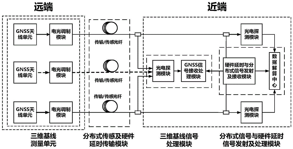
图2显示了本发明光纤监测装置应用于桥梁结构健康监测中的具体结构。硬件铺设方式如图2所示,在桥头和桥尾分别放置GNSS天线和电光调制器,从而构成三维基线测量单元;在桥上铺设两路传输光纤将三维基线测量单元所获得的光载GNSS信号传输至近端;由于该传输光纤同时还作为分布式光纤传感系统的传感光纤,因此图中将其表示为传输/传感光纤。远端的三维基线测量单元通过天线接收GNSS信号后,经过电光调制将GNSS信号调制到光载波上,再通过传输光纤传输至近端,由光电探测器恢复出GNSS信号。两路GNSS信号经过解算即可获取两路载波相位观测值,从而计算出两个天线间的三维基线向量,实现铺设部位的重点三维全向监测。传输光纤上可通过耦合器设置多个节点,天线可以放置在一条光纤上的任一节点处,从而实现灵活的大范围重点部分监测。在本实施例例中,选取光纤1上的节点1和光纤2上的节点10,监测桥头和桥尾的基线向量的变化。另一方面,在近端,通过硬件延时与分布式信号发射及接收模块发射宽带光探测信号,实现GNSS天线到接收模块间硬件时延监测,以提升三维监测的精度;同时,利用该宽带光探测信号,通过光纤中的瑞利散射,可以获得传感光纤上的分布式传感信息,从而实现GNSS天线间高精度三维监测与光纤沿线分布式监测的光纤多维监测。Fig. 2 shows the specific structure of the optical fiber monitoring device of the present invention applied to bridge structure health monitoring. The hardware laying method is shown in Figure 2. The GNSS antenna and the electro-optical modulator are respectively placed at the bridge head and the bridge tail to form a three-dimensional baseline measurement unit; The GNSS signal is transmitted to the near end; since the transmission fiber is also used as the sensing fiber of the distributed optical fiber sensing system, it is represented as a transmission/sensing fiber in the figure. After receiving the GNSS signal through the antenna, the three-dimensional baseline measurement unit at the far end modulates the GNSS signal onto the optical carrier through electro-optic modulation, and then transmits it to the near end through the transmission fiber, and recovers the GNSS signal by the photodetector. After the two GNSS signals are solved, the two carrier phase observations can be obtained, so as to calculate the three-dimensional baseline vector between the two antennas, and realize the key three-dimensional omnidirectional monitoring of the laying site. Multiple nodes can be set on the transmission fiber through couplers, and the antenna can be placed at any node on one fiber, so as to realize flexible monitoring of large-scale key parts. In this embodiment, the node 1 on the optical fiber 1 and the
本实施例通过复用光电探测模块和数据采集单元,对光纤内返回的信号进行单次采集,同时获取光纤沿线的散射信号和光纤端面的反射信号;在信号获取后,通过对光纤沿线的散射信号进行互相关处理获取分布式监测信息;通过对光纤端面的反射信号进行脉冲压缩处理,获取高精度的硬件延时信息,从而完成分布式解算和三维基线解算。In this embodiment, by multiplexing the photoelectric detection module and the data acquisition unit, the signal returned in the optical fiber is collected once, and the scattering signal along the optical fiber and the reflection signal of the end face of the optical fiber are obtained at the same time; Cross-correlation processing is performed on the signals to obtain distributed monitoring information; high-precision hardware delay information is obtained by performing pulse compression processing on the reflected signals of the fiber end faces, thereby completing distributed calculations and three-dimensional baseline calculations.
本发明所涉及的光纤分布式传感信息的采集与解算,载波相位单差模型,光纤长度的解算等均为现有技术,为便于公众理解,下面分别对其基本原理予以简单说明:The acquisition and calculation of optical fiber distributed sensing information involved in the present invention, the single-difference model of carrier phase, and the calculation of optical fiber length are all existing technologies. For the convenience of the public, the basic principles are briefly explained below:
三维基线的解算基于光载GNSS单差模型,可以实现三维高精度测量。该模型需要测量出天线到接收机之间的硬件延时信息,也就是光纤长度的测量精度,对其精度要求达到mm级。The calculation of the 3D baseline is based on the optical GNSS single-difference model, which can realize 3D high-precision measurement. This model needs to measure the hardware delay information between the antenna and the receiver, that is, the measurement accuracy of the optical fiber length, and its accuracy is required to reach mm level.
通过对不同天线做差,并且采用共时钟板卡设计的接收机消除钟差后,可得到载波相位单差模型:By making differences for different antennas and using the receiver designed with a common clock board to eliminate the clock difference, the carrier phase single-difference model can be obtained:

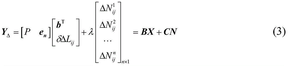
其中i和j表示不同的天线,k表示不同的卫星,


上述模型可简化为:The above model can be simplified as:
令载波相位测量精度和硬件延时测量精度分别为


则可知,硬件延时测量精度需要和载波相位测量精度达到同一水平,载波相位测量方法的精度可达mm级,故硬件延时测量也需要达到mm级。It can be seen that the hardware delay measurement accuracy needs to reach the same level as the carrier phase measurement accuracy, and the accuracy of the carrier phase measurement method can reach the mm level, so the hardware delay measurement also needs to reach the mm level.
为满足该需求,用于测量的宽带光探测信号必须具有足够高的空间分辨率,为此,本实施例中采用线性调频信号(LFM)作为探测信号,这样既可达到所需精度,假设线性调频信号扫频速率为γ,则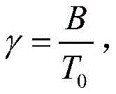

其中T为持续时间。可见,通过选择合适的扫频速率和持续时间,可以得到能够满足要求的空间分辨率。where T is the duration. It can be seen that by choosing an appropriate sweep rate and duration, a spatial resolution that can meet the requirements can be obtained.
对分布式信息的解算原理如下:The principle of solving distributed information is as follows:
分布式传感信息的解算来源于光纤中的瑞利散射,光波在光纤中传输时,会产生各个方向的散射光,但是由于光纤的约束特性,实际上其散射光只会表现为前向和背向两个方向。同时,由于光纤所处的外界环境会影响光纤中的光波,当外界环境发生变化时,如温度变化、光纤受到应力、光纤振动等,从探测端探测到的散射光频域信号,其中就含有光纤沿线的外界环境信息,将其解调后,可以得到能反映光纤沿线的外界情况的信号,从而实现对外界环境的监测。The solution of distributed sensing information comes from Rayleigh scattering in the optical fiber. When the light wave is transmitted in the optical fiber, it will generate scattered light in all directions. However, due to the constraints of the optical fiber, the scattered light will only appear in the forward direction. and back in both directions. At the same time, because the external environment of the optical fiber will affect the light waves in the optical fiber, when the external environment changes, such as temperature changes, optical fiber stress, optical fiber vibration, etc., the scattered light frequency domain signal detected from the detection end contains After demodulating the external environment information along the optical fiber, a signal that can reflect the external conditions along the optical fiber can be obtained, so as to realize the monitoring of the external environment.
如测试光纤的反射点位于Z处,τZ为Z处的反射点返回探测端的测试光与本振光间的时延差,则:If the reflection point of the test fiber is located at Z, τ Z is the time delay difference between the test light returning to the detection end and the local oscillator light at the reflection point at Z, then:
τZ=2Zn/c (6)τ Z =2Zn/c (6)
其中n为光纤折射率,c为光在真空中的传播速度。所以此时本振光与测试光之间的频差就是拍频,而光纤上每一个散射点与本振光之间的拍频信号有不同的固定频差,所以不同的拍频频差对应的不同位置的散射点,最终通过探测本振光与散射光之间的拍频信号的频率在光纤上定位,所以利用傅里叶变换将光电探测器采集的拍频时域信号变换到频域上,就可以得到光纤沿线不同位置上的信息。Among them, n is the refractive index of the fiber, and c is the propagation speed of light in vacuum. So at this time, the frequency difference between the local oscillator light and the test light is the beat frequency, and the beat frequency signal between each scattering point on the optical fiber and the local oscillator light has a different fixed frequency difference, so different beat frequency frequency differences correspond to Scattering points at different positions are finally located on the optical fiber by detecting the frequency of the beat frequency signal between the local oscillator light and the scattered light, so Fourier transform is used to transform the beat frequency time domain signal collected by the photodetector into the frequency domain , the information of different positions along the optical fiber can be obtained.
分布式信息解调方法如下:采集参考信号和测量信号,做傅里叶变化转换到距离域;采用滑动窗扫描距离域上的信号,划分为各个本地距离域信号;利用傅里叶反变换将各个本地距离域信号转换到波长域,得到本地瑞利散射光谱信号;对参考信号和测试信号的本地瑞利散射光谱信号做互相关,得到互相关峰偏移量,进而得到所述分布式传感信息。The distributed information demodulation method is as follows: collect reference signals and measurement signals, and convert them to the distance domain by Fourier transform; use a sliding window to scan the signals on the distance domain and divide them into various local distance domain signals; use inverse Fourier transform to convert Each local distance domain signal is converted to the wavelength domain to obtain a local Rayleigh scattering spectrum signal; the local Rayleigh scattering spectrum signal of the reference signal and the test signal is cross-correlated to obtain a cross-correlation peak offset, and then the distributed transmission spectrum is obtained. emotional information.
对三维基线解算原理如下:The principle of calculating the 3D baseline is as follows:
对于光纤上的不同节点,耦合器会使其在频谱上表现为明显的峰,通过不同节点对应拍频可解算出相应的硬件延时信息,可表示为:For different nodes on the optical fiber, the coupler will make it appear as an obvious peak on the spectrum, and the corresponding hardware delay information can be calculated through the corresponding beat frequency of different nodes, which can be expressed as:

其中fb为本振光与测试光之间的频差。Where f b is the frequency difference between the local oscillator light and the test light.
通过对不同天线做差,可以得到载波相位单差模型:By making the difference for different antennas, the carrier phase single-difference model can be obtained:

其中Δ是单差算子,通过单差可以消除大部分公共误差,例如电离层,对流层延时和卫星钟差。由于基线长度远小于卫星到天线之间的距离,可将

使用共时钟板卡的硬件设计,消除接收机钟差后,得到载波相位单差模型为:Using the hardware design of the common clock board, after eliminating the clock error of the receiver, the carrier phase single-difference model is obtained as:

在此方程中,卫星的载波相位差

综上可知,本发明能够同时实现二维分布式监测和重点部位的三维监测,而且可以通过两者的信息融合,提升三维监测的精度和监测范围,拓宽传感系统的应用场景。In summary, the present invention can realize two-dimensional distributed monitoring and three-dimensional monitoring of key parts at the same time, and can improve the accuracy and monitoring range of three-dimensional monitoring through the information fusion of the two, and broaden the application scenarios of the sensing system.
Claims (4)
Priority Applications (1)
| Application Number | Priority Date | Filing Date | Title |
|---|---|---|---|
| CN202111573260.4A CN114252022B (en) | 2021-12-21 | 2021-12-21 | Optical fiber multi-dimensional monitoring method and device based on GNSS signals |
Applications Claiming Priority (1)
| Application Number | Priority Date | Filing Date | Title |
|---|---|---|---|
| CN202111573260.4A CN114252022B (en) | 2021-12-21 | 2021-12-21 | Optical fiber multi-dimensional monitoring method and device based on GNSS signals |
Publications (2)
| Publication Number | Publication Date |
|---|---|
| CN114252022A CN114252022A (en) | 2022-03-29 |
| CN114252022B true CN114252022B (en) | 2023-02-24 |
Family
ID=80796414
Family Applications (1)
| Application Number | Title | Priority Date | Filing Date |
|---|---|---|---|
| CN202111573260.4A Active CN114252022B (en) | 2021-12-21 | 2021-12-21 | Optical fiber multi-dimensional monitoring method and device based on GNSS signals |
Country Status (1)
| Country | Link |
|---|---|
| CN (1) | CN114252022B (en) |
Citations (6)
| Publication number | Priority date | Publication date | Assignee | Title |
|---|---|---|---|---|
| CN101592475A (en) * | 2009-06-08 | 2009-12-02 | 中国计量学院 | Fully Distributed Optical Fiber Rayleigh and Raman Scattering Photon Strain and Temperature Sensors |
| CN108490481A (en) * | 2018-05-18 | 2018-09-04 | 惠安县金建达电子科技有限公司 | A kind of underground longitude and latitude monitoring device for geology field |
| CN108801153A (en) * | 2018-06-20 | 2018-11-13 | 苏州六幺四信息科技有限责任公司 | Optical fibre length measurement method and measuring device |
| CN109447048A (en) * | 2018-12-25 | 2019-03-08 | 苏州闪驰数控系统集成有限公司 | A kind of artificial intelligence early warning system |
| CN210719052U (en) * | 2019-12-02 | 2020-06-09 | 山西省交通科技研发有限公司 | Automatic monitoring system suitable for loess area slope deformation |
| CN111505633A (en) * | 2020-04-26 | 2020-08-07 | 中国科学院空天信息创新研究院 | Microwave photonic distributed radar imaging system and method |
Family Cites Families (2)
| Publication number | Priority date | Publication date | Assignee | Title |
|---|---|---|---|---|
| EP2832160A2 (en) * | 2012-03-30 | 2015-02-04 | Corning Optical Communications LLC | Location tracking for mobile terminals and related components and methods |
| CN106872071A (en) * | 2016-12-30 | 2017-06-20 | 江苏骏龙光电科技股份有限公司 | A kind of temp measuring method based on optical frequency domain reflection technology |
-
2021
- 2021-12-21 CN CN202111573260.4A patent/CN114252022B/en active Active
Patent Citations (6)
| Publication number | Priority date | Publication date | Assignee | Title |
|---|---|---|---|---|
| CN101592475A (en) * | 2009-06-08 | 2009-12-02 | 中国计量学院 | Fully Distributed Optical Fiber Rayleigh and Raman Scattering Photon Strain and Temperature Sensors |
| CN108490481A (en) * | 2018-05-18 | 2018-09-04 | 惠安县金建达电子科技有限公司 | A kind of underground longitude and latitude monitoring device for geology field |
| CN108801153A (en) * | 2018-06-20 | 2018-11-13 | 苏州六幺四信息科技有限责任公司 | Optical fibre length measurement method and measuring device |
| CN109447048A (en) * | 2018-12-25 | 2019-03-08 | 苏州闪驰数控系统集成有限公司 | A kind of artificial intelligence early warning system |
| CN210719052U (en) * | 2019-12-02 | 2020-06-09 | 山西省交通科技研发有限公司 | Automatic monitoring system suitable for loess area slope deformation |
| CN111505633A (en) * | 2020-04-26 | 2020-08-07 | 中国科学院空天信息创新研究院 | Microwave photonic distributed radar imaging system and method |
Non-Patent Citations (3)
| Title |
|---|
| A Multi-Antenna GNSS-Over-Fiber System for High Accuracy Three-Dimensional Baseline Measurement;Xin Jiang;Xiangchuan Wang;Angran Zhao;Jianping Yao;Shilong Pan;《Journal of Lightwave Technology》;20190610;第37卷(第17期);全文 * |
| Xin Jiang ; Xiangchuan Wang ; Shilong Pan.A Multi-antenna GNSS-over-fiber System with High Vertical Precision.《2018 International Topical Meeting on Microwave Photonics (MWP)》.2018, * |
| 桥梁健康无线监测系统关键技术研究;郝红梅;《市政技术》;20110710(第04期);第124-126页 * |
Also Published As
| Publication number | Publication date |
|---|---|
| CN114252022A (en) | 2022-03-29 |
Similar Documents
| Publication | Publication Date | Title |
|---|---|---|
| CN102538846B (en) | Method for calculating location of sensor fibre | |
| CN107101658B (en) | A fast positioning method for phase-sensitive optical time domain reflectance distributed optical fiber sensing system | |
| CN102759371A (en) | COTDR (coherent detection based optical time-domain reflectometry) fused long-distance coherent detection brilouin optical time-domain analyzer | |
| CN101441092B (en) | Perimeter protection sensing positioning system based on coherent light time domain reflection | |
| CN102879081B (en) | A kind of data processing method in distributed optical fiber vibration system | |
| CN108415067B (en) | Earthquake wave measuring system based on microstructure optical fiber distributed acoustic wave sensing | |
| CN101806594B (en) | Array type wave monitoring device and wave measurement method thereof | |
| CN110161458B (en) | A Sound Source Localization System Based on Fiber-optic Michelson Interferometer | |
| CN114034326B (en) | Optical cable detection method, device, equipment and storage medium | |
| CN204719233U (en) | A kind of target detection unit based on double-frequency laser | |
| CN109541621B (en) | A vibration compensation method for frequency scanning interferometric absolute ranging system | |
| CN105222815A (en) | Based on the phase sensitive optical time domain reflectometer of 120 degree of difference interferometers | |
| CN103017887A (en) | Optical fiber vibration sensing system and detection method thereof | |
| CN209296053U (en) | A kind of Distributed Detection pipeline and system | |
| CN106612146A (en) | System for rapidly finding and precisely positioning ground position of fault point of communication optical fiber | |
| CN209296054U (en) | A kind of distributed fiber grating detection pipeline and system | |
| CN202252873U (en) | Interferometric distributed optical fiber underwater long gas pipeline leak detection device | |
| CN114252022B (en) | Optical fiber multi-dimensional monitoring method and device based on GNSS signals | |
| CN115950372B (en) | Distributed multi-dimensional sensing optical fiber shape sensing measurement system and method | |
| CN112033567A (en) | An Optical Fiber Sensing System for Separate Measurement of OPGW Overhead Ground Wire Temperature and Vibration | |
| US20160252371A1 (en) | Method and system using wavelength division multiplexing for eliminating and reducing light diffusion and light reflection interference in interference path | |
| CN101937602A (en) | Multi-site optical fiber vibration invasion monitoring device | |
| CN202433122U (en) | Distributed intelligent power grid optical fiber temperature measurement system | |
| CN203432574U (en) | Distributed monitoring system for structural settlement on basis of optical-fiber ultrasonic sensing technology | |
| Wang et al. | Multiantenna GPS-over-fiber system for attitude determination using phase-derived range measurement |
Legal Events
| Date | Code | Title | Description |
|---|---|---|---|
| PB01 | Publication | ||
| PB01 | Publication | ||
| SE01 | Entry into force of request for substantive examination | ||
| SE01 | Entry into force of request for substantive examination | ||
| GR01 | Patent grant | ||
| GR01 | Patent grant |