CN114221862A - Network configuration method and device of equipment, electronic equipment and storage medium - Google Patents
Network configuration method and device of equipment, electronic equipment and storage medium Download PDFInfo
- Publication number
- CN114221862A CN114221862A CN202111512403.0A CN202111512403A CN114221862A CN 114221862 A CN114221862 A CN 114221862A CN 202111512403 A CN202111512403 A CN 202111512403A CN 114221862 A CN114221862 A CN 114221862A
- Authority
- CN
- China
- Prior art keywords
- network
- node device
- node
- abnormal
- current
- Prior art date
- Legal status (The legal status is an assumption and is not a legal conclusion. Google has not performed a legal analysis and makes no representation as to the accuracy of the status listed.)
- Granted
Links
Images


Classifications
-
- H—ELECTRICITY
- H04—ELECTRIC COMMUNICATION TECHNIQUE
- H04L—TRANSMISSION OF DIGITAL INFORMATION, e.g. TELEGRAPHIC COMMUNICATION
- H04L41/00—Arrangements for maintenance, administration or management of data switching networks, e.g. of packet switching networks
- H04L41/08—Configuration management of networks or network elements
- H04L41/0803—Configuration setting
-
- H—ELECTRICITY
- H04—ELECTRIC COMMUNICATION TECHNIQUE
- H04L—TRANSMISSION OF DIGITAL INFORMATION, e.g. TELEGRAPHIC COMMUNICATION
- H04L12/00—Data switching networks
- H04L12/28—Data switching networks characterised by path configuration, e.g. LAN [Local Area Networks] or WAN [Wide Area Networks]
- H04L12/2803—Home automation networks
- H04L12/2807—Exchanging configuration information on appliance services in a home automation network
-
- H—ELECTRICITY
- H04—ELECTRIC COMMUNICATION TECHNIQUE
- H04L—TRANSMISSION OF DIGITAL INFORMATION, e.g. TELEGRAPHIC COMMUNICATION
- H04L41/00—Arrangements for maintenance, administration or management of data switching networks, e.g. of packet switching networks
- H04L41/08—Configuration management of networks or network elements
- H04L41/0803—Configuration setting
- H04L41/0823—Configuration setting characterised by the purposes of a change of settings, e.g. optimising configuration for enhancing reliability
- H04L41/0826—Configuration setting characterised by the purposes of a change of settings, e.g. optimising configuration for enhancing reliability for reduction of network costs
-
- H—ELECTRICITY
- H04—ELECTRIC COMMUNICATION TECHNIQUE
- H04L—TRANSMISSION OF DIGITAL INFORMATION, e.g. TELEGRAPHIC COMMUNICATION
- H04L41/00—Arrangements for maintenance, administration or management of data switching networks, e.g. of packet switching networks
- H04L41/08—Configuration management of networks or network elements
- H04L41/0876—Aspects of the degree of configuration automation
- H04L41/0886—Fully automatic configuration
-
- H—ELECTRICITY
- H04—ELECTRIC COMMUNICATION TECHNIQUE
- H04L—TRANSMISSION OF DIGITAL INFORMATION, e.g. TELEGRAPHIC COMMUNICATION
- H04L41/00—Arrangements for maintenance, administration or management of data switching networks, e.g. of packet switching networks
- H04L41/08—Configuration management of networks or network elements
- H04L41/0889—Techniques to speed-up the configuration process
-
- H—ELECTRICITY
- H04—ELECTRIC COMMUNICATION TECHNIQUE
- H04L—TRANSMISSION OF DIGITAL INFORMATION, e.g. TELEGRAPHIC COMMUNICATION
- H04L41/00—Arrangements for maintenance, administration or management of data switching networks, e.g. of packet switching networks
- H04L41/08—Configuration management of networks or network elements
- H04L41/0893—Assignment of logical groups to network elements
Landscapes
- Engineering & Computer Science (AREA)
- Computer Networks & Wireless Communication (AREA)
- Signal Processing (AREA)
- Automation & Control Theory (AREA)
- Small-Scale Networks (AREA)
- Data Exchanges In Wide-Area Networks (AREA)
Abstract
The embodiment of the application provides a network configuration method and device of equipment, electronic equipment and a storage medium, and relates to the technical field of intelligent home. The method comprises the following steps: receiving message data uploaded by each node device in the current network, performing network detection on each node device based on the message data to obtain a network diagnosis result, and if the node device with the network abnormality in the current network is determined according to the network diagnosis result, kicking out the node device with the network abnormality from the current network to indicate the node device with the network abnormality to be connected to a matched network, so that remote automatic network configuration of the node device is realized, the cost of node device configuration is reduced, and the efficiency of node device configuration is improved.
Description
Technical Field
The present application relates to the field of smart home technologies, and in particular, to a method and an apparatus for configuring a network of devices, an electronic device, and a storage medium.
Background
With the development of communication technology and smart homes, in an actual application scene, a ZigBee wireless network system has more common interference sources and limited transmission distance, if no repeater is provided, signal attenuation is obvious, and therefore, the signals of node equipment are not good, the problem of the node equipment is solved at present, an engineer needs to arrive at an equipment site, the node equipment is positioned by capturing a packet for a long time, wireless messages are analyzed, and the node equipment is configured on the site abnormally, so that the cost is high, and the efficiency is low when the node equipment is configured.
Disclosure of Invention
In view of the above problems, the present application provides a method and an apparatus for configuring a network of devices, an electronic device, and a storage medium to solve the above problems.
In a first aspect, an embodiment of the present application provides a method for configuring a network of devices, where the method includes: receiving message data uploaded by each node device in the current network; performing network detection on each node device based on the message data to obtain a network diagnosis result; and if the node equipment with the network abnormality exists in the current network according to the network diagnosis result, kicking the node equipment with the network abnormality out of the current network so as to indicate that the node equipment with the network abnormality is connected to the matched network.
In a second aspect, an embodiment of the present application provides an apparatus for configuring a network of devices, where the apparatus includes: the message data receiving module is used for receiving message data uploaded by each node device in the current network; a network diagnosis result obtaining module, configured to perform network detection on each node device based on the message data to obtain a network diagnosis result; and the equipment kicking-out module is used for kicking out the abnormal node equipment of the network from the current network to indicate the abnormal node equipment of the network to be connected to the matched network if the abnormal node equipment of the network is determined to exist in the current network according to the network diagnosis result.
In some embodiments, the network diagnostic result acquisition module comprises: a network parameter acquisition submodule and a network detection submodule, wherein: and the network parameter acquisition submodule is used for acquiring the network parameters of each node device in a preset time period from the message data of each node device. And the network detection submodule is used for carrying out network detection on each node device according to the network parameters to obtain network diagnosis results respectively corresponding to each node device.
In some embodiments, the network detection submodule includes: an anomaly number determination unit and a network anomaly determination unit, wherein: and the abnormal frequency determining unit is used for determining the network abnormal frequency of each node device based on the network parameters. And the network abnormity determining unit is used for determining that the network diagnosis result corresponding to each node device is the network abnormity when the network abnormity frequency is greater than the preset abnormity frequency. And the equipment kicking-out module is used for kicking out the abnormal node equipment of the network from the current network to indicate the abnormal node equipment of the network to be connected to the matched network if the abnormal node equipment of the network is determined to exist in the current network according to the network diagnosis result.
In some embodiments, the device kick-out module comprises: the device number acquisition submodule and the node device configuration submodule, wherein: the equipment quantity obtaining submodule is used for obtaining the equipment quantity of the node equipment with the network abnormality in the current network if the node equipment with the network abnormality in the current network is determined according to the network diagnosis result; and the node equipment configuration submodule is used for kicking out each node equipment in the current network to indicate each node equipment in the current network to be connected to the matched network when the network condition of the current network is determined to be abnormal when the equipment number of the node equipment with network abnormality is larger than the number threshold.
In some embodiments, the network configuration means of the device further comprises: network scanning module and target broadcast emission module, wherein: and the network scanning module is used for controlling the node equipment with the abnormal network state to perform network scanning. The target broadcast transmitting module is used for controlling network equipment under a target network to transmit a target broadcast so as to indicate that the node equipment with the abnormal network state is added into the target network when the target broadcast is scanned; wherein the target broadcast is used for indicating that the target network allows the node device to access the network.
In some embodiments, the target broadcast transmitting module comprises: a target account number obtaining submodule, a network quality obtaining submodule and a target network selecting submodule, wherein: and the target account acquisition submodule is used for acquiring the target account corresponding to the node equipment with the abnormal network state. And the network quality acquisition submodule is used for acquiring the network quality corresponding to the associated network associated with the target account. And the target network selection submodule is used for selecting a target network from the associated networks corresponding to the target account according to the network quality.
In a third aspect, an embodiment of the present application provides an electronic device, including one or more processors and a memory; one or more computer programs, wherein the one or more computer programs are stored in the memory and configured to be executed by the one or more processors, the one or more computer programs configured to perform the methods described above.
In a fourth aspect, the present application provides a computer-readable storage medium, in which a program code is stored, and the program code can be called by a processor to execute the above method.
According to the network configuration method and device of the equipment, the electronic equipment and the storage medium, firstly, message data uploaded by each node equipment in the current network are received, network detection is carried out on each node equipment based on the message data, a network diagnosis result is obtained, if the node equipment with the network abnormality in the current network is determined according to the network diagnosis result, the node equipment with the network abnormality is kicked out from the current network so as to indicate the node equipment with the network abnormality to be connected to the matched network, and therefore remote automatic network configuration of the node equipment is achieved, cost of node equipment configuration is reduced, and efficiency of node equipment configuration is improved.
These and other aspects of the present application will be more readily apparent from the following description of the embodiments.
Drawings
In order to more clearly illustrate the technical solutions in the embodiments of the present application, the drawings needed to be used in the description of the embodiments are briefly introduced below, and it is obvious that the drawings in the following description are only some embodiments of the present application, and it is obvious for those skilled in the art to obtain other drawings based on these drawings without creative efforts.
Fig. 1 is a schematic diagram illustrating a first application scenario of a network configuration method that can be used in a device provided in an embodiment of the present application;
fig. 2 is a schematic diagram illustrating a second application scenario of a network configuration method that can be used for a device provided in an embodiment of the present application;
fig. 3 is a schematic diagram illustrating a node device suitable for use in embodiments of the present application;
fig. 4 is a flowchart illustrating a network configuration method of a device according to an embodiment of the present application;
fig. 5 is a schematic diagram illustrating diagnostic information of a node device provided in an embodiment of the present application;
fig. 6 is a flowchart illustrating a network configuration method of a device according to an embodiment of the present application;
fig. 7 shows a flow chart of step S230 of the network configuration method of the device shown in fig. 6 of the present application;
fig. 8 is a flowchart illustrating a network configuration method of a device according to an embodiment of the present application;
fig. 9 shows a flow chart of step S360 of the network configuration method of the device shown in fig. 8 of the present application;
fig. 10 shows a block diagram of a network configuration device of an apparatus provided by an embodiment of the present application;
fig. 11 shows a block diagram of an electronic device according to an embodiment of the present application;
fig. 12 shows a block diagram of a computer-readable storage medium according to an embodiment of the present application.
Detailed Description
In order to make the technical solutions better understood by those skilled in the art, the technical solutions in the embodiments of the present application will be clearly and completely described below with reference to the drawings in the embodiments of the present application.
With the development of communication technology and smart homes, in an actual application scene, a ZigBee wireless network system has more common interference sources and limited transmission distance, if no repeater is provided, signal attenuation is obvious, and therefore, the signals of node equipment are not good, the problem of the node equipment is solved at present, an engineer needs to arrive at an equipment site, the node equipment is located by long-time packet grabbing, wireless messages are analyzed, and when the node equipment is configured on the site abnormally, the node equipment is configured, the cost is high, and the efficiency is low.
In view of the above technical problems, the inventors have found through long-term research and provide a method and an apparatus for network configuration of a device, an electronic device, and a storage medium, where after receiving message data of a node device in a current network, the node device is subjected to network detection according to the message data, and when a diagnosis result determines that the network of the node device in the current network is abnormal, the node device is kicked out from the current network and connected to a matching network, so as to implement remote automatic network configuration of the node device, reduce the cost of node device configuration, and improve the efficiency of node device configuration. The network configuration method of the specific device is described in detail in the following embodiments.
An application scenario of the network configuration method applied to the device provided in the embodiment of the present application is described below.
Referring to fig. 1, fig. 1 is a schematic diagram illustrating a first application scenario of a network configuration method that can be used for a device provided in an embodiment of the present application. The network configuration method of the device provided by the embodiment of the application can be applied to the smart home system 10 shown in fig. 1. The smart home system 10 may include a node device 300, a first gateway 210, a second gateway 220, and a cloud server 100. The cloud server 100 is connected to a first gateway 210 and a second gateway 220, respectively, the first gateway 210 may be connected to one or more node devices 300, and the second gateway 220 may also be connected to one or more node devices 300.
The number of the node apparatuses 300 may be one or more. When the number of the node apparatuses 300 is one, one node apparatus 300 may be connected to the first gateway 210 or the second gateway 220. When the number of the node apparatuses 300 is plural, the plural node apparatuses 300 may be connected to the first gateway 210 and/or the second gateway 220. As one mode, assuming that the plurality of node devices 300 includes a first node device and a second node device, the first node device and the second node device may both be connected to the first gateway 210, or the first node device and the second node device may both be connected to the second gateway 220, or the first node device is connected to the first gateway 210, and the second node device is connected to the second gateway 220, which is not limited herein.
In some embodiments, the node device may be a ZigBee node device in a ZigBee network. There are many types of node devices, including but not limited to various electronic devices such as intelligent appliances, intelligent switches, etc. The intelligent household appliance may be different versions of refrigerator, washing machine, air conditioner, television and other appliances, and is not limited herein. For example, when the intelligent appliance is a refrigerator, the intelligent appliance can be an XX first-generation refrigerator, an XX second-generation refrigerator and the like; when the intelligent household appliance is a washing machine, the intelligent household appliance can be an XX first-generation washing machine, an XX second-generation washing machine and the like; when the intelligent household appliance is an air conditioner, the intelligent household appliance can be an XX first-generation air conditioner, an XX second-generation air conditioner and the like; when the intelligent household appliance is a television, the intelligent household appliance can be an XX first generation television, an XX second generation television and the like.
By one way, the node device 300 wirelessly communicates with the cloud server 100 through the first gateway 210 or the second gateway 220 to realize data interaction between the node device 300 and the cloud server. Alternatively, the node apparatus 300 is directly connected to the cloud server 100 to implement data interaction between the node apparatus 300 and the cloud server.
Further, the smart home system 10 may further include a third gateway, a fourth gateway … …, and an nth gateway, which is not limited herein.
The node device 300 may include, but is not limited to, a door and window sensor, a smart switch, a light, an air conditioner, a curtain, a television, a refrigerator, and a fan, among others. For example, referring to fig. 2, fig. 2 is a schematic diagram illustrating a second application scenario of a network configuration method that can be used for a device provided in the present embodiment, as shown in fig. 2, the node device 300 may include a switch 310, a switch 320, a socket 330, a socket 340, and the like, which is not limited herein. Referring to fig. 3, fig. 3 is a schematic diagram illustrating a node device suitable for use in the embodiment of the present application, and as shown in fig. 3, the node device 300 may include a television 300A, an air conditioner 300B, a camera 300C, a lamp 300D, and the like, which is not limited herein.
The cloud server 100 may be a cloud server providing basic cloud computing services such as cloud services, a cloud database, cloud computing, a cloud function, cloud storage, a network service, cloud communication, middleware services, a domain name service, a security service, and a big data and artificial intelligence platform.
Embodiments of the present application will be described in detail below with reference to the accompanying drawings.
Referring to fig. 4, fig. 4 is a flowchart illustrating a network configuration method of a device according to an embodiment of the present application. In a specific embodiment, the network configuration method of the device may be applied to an electronic device, and the electronic device may specifically be the cloud server 100 shown in fig. 1. As will be described in detail with respect to the flow shown in fig. 4, the network configuration method of the device may specifically include the following steps:
step S110: and receiving message data uploaded by each node device in the current network.
In this embodiment, each node device in the current network may upload message data, and the cloud server may receive the message data uploaded by each node device in the current network, where the cloud server may directly receive the message data uploaded by each node device in the current network; the cloud server can also receive message data uploaded by each node device in the current network through the gateway. As a mode, the message data of the node device may be collected by each node device and periodically actively reported through a ZigBee wireless message, so that the cloud server may receive the message data uploaded by each node device in the current network. As another mode, the diagnostic information may also be actively sent to the gateway through a ZigBee wireless message after being collected by each node device, and the gateway periodically reports the diagnostic information, so that the cloud server may receive message data uploaded by each node device in the current network.
In some embodiments, the message data of the node device includes, but is not limited to, information such as the number of times of message transmission, the number of times of message retransmission, the number of times of message reception, and the like.
In some cases, the number of times of sending the message may be information such as the number of times of sending a MAC layer message, the number of times of sending an NWK layer message, and the number of times of sending an APS layer message, which is not limited herein; the number of retransmission of the packet may be the number of retransmission of the MAC layer packet, the number of retransmission of the NWK layer packet, and the number of retransmission of the APS layer packet, which is not limited herein; the number of times of receiving the packet may be information such as the number of times of receiving the MAC layer packet, the number of times of receiving the NWK layer packet, and the number of times of receiving the APS layer packet, which is not limited herein.
In some embodiments, the cloud server may obtain the message data uploaded by each node device in the current network, and the cloud server may further store the message data uploaded by each node device in the current network for one or more weeks in a memory of the cloud server, where a specific storage duration is not limited herein, the message data is used to analyze a network condition problem, and after the cloud server is restarted, the cloud server clears the message data uploaded by each node device in the current network; when the cloud server determines that the count value corresponding to the diagnostic information of the first ZigBee node device reaches the maximum value, the cloud server may also clear the message data uploaded by each node device in the current network.
In some embodiments, based on the packet data uploaded by each node device in the current network stored by the cloud server, the cloud server platform may plot a time-parameter graph of specific parameters of the packet data uploaded by each node device in the current network, for example, according to the Mac layer packet sending times MacTxUcast, the cloud server platform may show a graph of the relationship between time and MacTxUcast for the Mac layer packet sending times MacTxUcast (fig. 5). Meanwhile, the cloud server can store the diagnostic information of the first ZigBee node device for one or more weeks, wherein the specific storage time is not limited herein, and the cloud server can store the message data uploaded by each node device, so that the cloud server can analyze the network problem of each node device conveniently, and can inquire the historical diagnostic information of the message data uploaded by each node device conveniently. The cloud server platform is an IoT internet of things cloud + end integrated management platform, and based on a cloud computing platform, platform management functions such as CMP (connection management), DMP (device management platform), AEP (application enablement platform), and BAP (business analysis platform) are realized, access management of various intelligent hardware, robots, intelligent screens, intelligent sound boxes, intelligent homes and devices is supported, and fault sensing, device positioning, human-computer interaction, and intelligent customer service functions are provided.
Step S120: and performing network detection on each node device based on the message data to obtain a network diagnosis result.
In this embodiment, the node device may directly upload the message data to the cloud server, and the cloud server performs network detection on the network status of each node device after analyzing the message data reported by each node device, to obtain a network diagnosis result, where the network diagnosis result is used to determine whether the network status of each node device is abnormal.
Step S130: and if the node equipment with the network abnormality exists in the current network according to the network diagnosis result, kicking the node equipment with the network abnormality out of the current network so as to indicate that the node equipment with the network abnormality is connected to the matched network.
In this embodiment, network detection may be performed on each node device according to the message data to obtain a network diagnosis result, and when the network result determines that a node device with network abnormality exists in the current network, the cloud server kicks the node device with network abnormality out of the current network. It should be noted that the step of kicking out the node device with the network abnormality from the current network means to disconnect the node device with the network abnormality from the current network.
In some embodiments, each node device may also be directly connected to the cloud server, after the cloud server performs network detection on the packet data uploaded by each node device, the cloud server makes a network diagnosis result on the network status of each node device, determines the network status of each node device based on the network diagnosis result, and when the node device has a network abnormality in the current network, directly kicks out the node device with the network abnormality from the cloud server.
In some embodiments, the node device may be connected to the current network through the coordinator, and when determining that the node device with the network abnormality exists in the current network according to the network diagnosis result, the cloud server may kick the node device with the network abnormality out of the first gateway in a manner of kicking the coordinator out of the current network.
According to the network configuration method of the device, the cloud server receives message data uploaded by each node device in the current network, network detection is performed on each node device based on the message data to obtain a network diagnosis result, and if the node device with the network abnormality in the current network is determined according to the network diagnosis result, the node device with the network abnormality is kicked out from the current network to indicate the node device with the network abnormality to be connected to the matched network, so that remote automatic network configuration of the node device is achieved, the cost of node device configuration is reduced, and the efficiency of node device configuration is improved.
Referring to fig. 6, fig. 6 is a flowchart illustrating a network configuration method of a device according to an embodiment of the present application. As will be described in detail with respect to the flow shown in fig. 6, the method for configuring a network of a node device may specifically include the following steps:
step S210: and receiving message data uploaded by each node device in the current network.
For detailed description of step S210, please refer to step S110, which is not described herein again.
Step S220: and acquiring the network parameters of each node device in a preset time period from the message data of each node device.
In this embodiment, the cloud server may obtain network parameters of each node device in a preset time period from the packet data of each node device, for example, the APS layer packet retransmission times are greater than 3 times, the packet transmission failure times are greater than 7 times, and the route lookup times are greater than 3 times in a period from 12 points to 2 points by the node device; in a time period from 2 points to 4 points, the first ZigBee node device retransmits the APS layer message for more than 3 times, fails to transmit the message for more than 9 times, searches for the route for more than 6 times and the like.
In some embodiments, the network parameters of each node device may include, but are not limited to, at least one of the number of retransmission of messages, the number of failure of transmission of messages, the number of route lookups, and the trend of the number of times.
Step S230: and performing network detection on each node device according to the network parameters to obtain network diagnosis results respectively corresponding to each node device.
In this embodiment, after the cloud server obtains the network parameters of each node device within a preset time period, the cloud server performs network detection on the network parameters to obtain network diagnosis results corresponding to each node device, and as a manner, when the network parameters meet preset abnormal conditions set by the cloud server, it may be determined that the network diagnosis result of the node device in the current network is a network abnormality; when the network parameter does not meet the preset abnormal condition set by the cloud server, it can be determined that the network diagnosis result of the node device in the current network is normal.
In some cases, the preset abnormal condition may be a preset abnormal number of network parameters, for example, when the number of network parameters exceeds the preset abnormal number of network parameters, it may be determined that the network diagnosis result of the node changing device in the current network is a network abnormality; when the number of times of the network parameters does not exceed the preset abnormal number of times, the network diagnosis result of the node equipment in the current network can be determined to be that the network is normal. For example, the number of times of retransmission of a packet is preset to be 3, the number of times of failure of transmission of a packet is preset to be 3 in the cloud server, and when the number of times of retransmission of an APS layer packet of the node device is 4, and the number of times of retransmission of an APS layer packet of the node device is greater than 3, it can be determined that the number of times of retransmission is greater than the preset number of times of retransmission, that is, it is determined that the network diagnosis result of the node device in the current network is network abnormality; when the MAC layer packet transmission failure times of the node device is 7 times and the MAC layer packet transmission failure times of the node device is greater than 3 times, it may be determined that the abnormal times are greater than the preset abnormal times, that is, it is determined that the network diagnosis result of the node device in the current network is the network abnormality.
In other cases, the preset abnormal condition may also be a preset abnormal duration for obtaining the network parameter, and obtaining an abnormal duration of the network data, for example, when the duration for obtaining the network parameter is longer than the preset abnormal duration, it may be determined that the network diagnosis result of the node device in the current network is a network abnormality; when the duration of the acquired network parameters is not longer than the preset abnormal duration, the network diagnosis result of the node equipment in the current network can be determined to be normal.
Referring to fig. 7, fig. 7 is a flowchart illustrating a step S230 of the network configuration method of the device shown in fig. 6 according to the present application. In this embodiment, the cloud server is further connected to a plurality of gateways to be determined, and as will be described in detail with respect to the flow shown in fig. 7, the method may specifically include the following steps:
step S231: and determining the network abnormal times of each node device based on the network parameters.
In this embodiment, the number of times of abnormality of each node device may be determined according to a network parameter. The network parameters may include, but are not limited to, the number of retransmission messages, the number of failure messages, the number of route lookups, and the number variation trend. For example, the number of times of retransmission of the APS layer packet of one of the node devices is greater than 3; the MAC layer message sending failure times of one node device in each node device is more than 7; the route searching times of one node device in each node device is more than 3; the number variation trend is an extension of the accumulated number, and the abnormal number of one node device in each node device can be determined.
In some embodiments, the number of retransmission of the packet may be information such as the number of retransmission of the MAC layer packet, the number of retransmission of the NWK layer packet, the number of retransmission of the APS layer packet, and the like, which is not limited herein; the number of the message transmission failures may be a number of MAC layer message transmission failures, a number of NWK layer message transmission failures, and a number of APS layer message transmission failures, which is not limited herein.
In some embodiments, the network parameters shown in table 1 may include information such as the number of times of packet retransmission, the number of times of packet transmission failure, and the number of times of route lookup, which may be stored in a cloud server, where the network parameters in table 1 are used for the cloud server to analyze the network condition and the network problem of a gateway where a node device is located, and the network parameters in table 1 are only part of network data, where a cluster ID is represented as identification information of a data cluster and a feature ID is represented as identification information of a feature.
TABLE 1
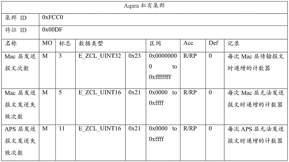
Step S232: and when the network abnormity frequency is greater than the preset abnormity frequency, determining that the network diagnosis result corresponding to each node device is the network abnormity.
In this embodiment, a preset abnormal frequency may be preset and stored in the cloud server, and when the network abnormal frequency is greater than the preset abnormal frequency, it may be determined that the network diagnosis result corresponding to each node device is determined to be a network abnormality; when the network abnormal times are smaller than the preset abnormal times, the network diagnosis result corresponding to each node device can be determined to be that the network is normal. For example, the number of times of retransmission of the preset packet in the cloud server is 3, the number of times of failure of transmission of the packet is 3, and when the number of times of retransmission of the APS layer packet of the node device is 4, and the number of times of retransmission of the APS layer packet of the node device is greater than 3, it may be determined that the number of times of retransmission is greater than the number of times of the preset abnormality, that is, it is determined that the network diagnosis result corresponding to each node device is a network abnormality; when the MAC layer packet transmission failure times of the node device is 7 times and the MAC layer packet transmission failure times of the node device is greater than 3 times, it may be determined that the abnormal times are greater than the preset abnormal times, that is, it is determined that the network diagnosis result corresponding to each node device is a network abnormality.
Step S240: and if the node equipment with the network abnormality exists in the current network according to the network diagnosis result, kicking the node equipment with the network abnormality out of the current network so as to indicate that the node equipment with the network abnormality is connected to the matched network.
For a detailed description of step S240, please refer to step S130, which is not described herein again.
Compared with the network configuration method of the device shown in fig. 4, the network configuration method of the device provided in an embodiment of the present application may further obtain the message data uploaded by each node device, obtain the network parameters of each node device within the preset time period from the message data, perform network detection on each node device according to the network parameters, obtain the network diagnosis results corresponding to each node device, and configure the node device with the abnormal network according to the diagnosis results, thereby improving the network condition of the node device with the abnormal network, and simultaneously implement remote automatic configuration of the node device, so as to reduce the cost of node device configuration and improve the efficiency of node device configuration.
Referring to fig. 8, fig. 8 is a flowchart illustrating a network configuration method for a device according to still another embodiment of the present application. As will be described in detail with respect to the flow shown in fig. 8, the network configuration method of the device may specifically include the following steps:
step S310: and receiving message data uploaded by each node device in the current network.
Step S320: and performing network detection on each node device based on the message data to obtain a network diagnosis result.
For the detailed description of steps S310 to S320, please refer to steps S110 to S120, which are not described herein again.
Step S330: and if the node equipment with the network abnormality in the current network is determined according to the network diagnosis result, acquiring the equipment number of the node equipment with the network abnormality in the current network.
In this embodiment, if the node device with the network abnormality in the current network is determined according to the network diagnosis result, the number of the node devices with the network abnormality in the current network is obtained. For example, the cloud server analyzes the network diagnosis result, determines that the node equipment with the network abnormality exists in the current network, and if the equipment number of the node equipment with the network abnormality is 1, acquires that the equipment number of the node equipment with the network abnormality exists in the current network is 1; the cloud server analyzes the network diagnosis result, determines the node device with the network abnormality in the current network, can determine that the first node device and the second node device are abnormal in the current network, and can determine that the third node is normal in the current network condition, so that the device number of the node device with the network abnormality in the current network is 2, and the device number of the node device with the network abnormality in the current network is 2.
Step S340: when the number of the node devices with network abnormality is larger than the number threshold, determining that the network condition of the current network is abnormal, kicking out each node device in the current network to indicate each node device in the current network to be connected to the matched network.
In this embodiment, a quantity threshold may be preset and stored in the cloud server, and when the number of devices of the node device having the network abnormality is greater than the quantity threshold, it is determined that the network condition of the current network is abnormal, and then each node device in the current network is kicked out; and when the equipment number of the node equipment with the network abnormality is smaller than the number threshold, determining that the network condition of the current network is normal.
Step S350: and controlling the abnormal node equipment of the network to scan the network.
In this embodiment, the node device with the network node abnormality may be controlled to perform network scanning, and it is understood that the purpose of the network scanning is to scan a matching network and connect the node device with the network node abnormality to the matching network.
Step S360: controlling network equipment under a target network to transmit a target broadcast so as to indicate that node equipment with abnormal network state joins the target network when scanning the target broadcast; wherein the target broadcast is used for indicating that the target network allows the node device to access the network.
In this embodiment, a network device in a target network is controlled to transmit a target broadcast, so as to indicate that a node device with an abnormal network state joins the target network when the node device scans the target broadcast. Wherein, the target broadcast is used for indicating the target network to allow the node device to access the network. The network device may be a device having a coordinator function, and as one mode, the network device may be a gateway, and a coordinator may be provided in the gateway as a network device in which the gateway and the coordination area are integrated. Alternatively, the network device may also be a coordinator.
It should be noted that, generally, a ZigBee network needs a coordinator to broadcast a node device allowed to access the network, and meanwhile, a node device has a network access requirement or a network access intention, but the location information of the node device with the network abnormality is unknown, so that all the coordinator needs to be started to broadcast the node device allowed to access the network with the network abnormality, a cloud server obtains the location information of the node device with the network abnormality, determines a network under a target account corresponding to the node device with the network abnormality as a network to be accessed, determines a target network according to the network quality of the network to be accessed, and adds the node device with the network abnormality into the target network.
Referring to fig. 9, fig. 9 is a flowchart illustrating a step S360 of the network configuration method of the device shown in fig. 8 according to the present application. As will be explained in detail with respect to the flow shown in fig. 9, the method may specifically include the following steps:
step S361: and acquiring the target account corresponding to the node equipment with the abnormal network state.
In this embodiment, the cloud server obtains a target account corresponding to a node device with an abnormal network state, where the corresponding account includes a self account of the node device and an account associated with the node device. It should be noted that the account corresponding to the node device with the abnormal network state is an Application (APP) bound to the account corresponding to the node device, an account (Identity document, ID) of the client, and another account having the same authority as the account, such as a parent account, and is not limited herein.
Step S362: and acquiring the network quality corresponding to the associated network associated with the target account.
In some embodiments, when there is one associated network associated with the target account, the network quality of the associated network associated with the target account may be determined, and the network quality corresponding to the associated network associated with the target account may be obtained.
In some embodiments, when there are multiple associated networks associated with the target account, the associated network with the best signal may be selected from the multiple associated networks through a competition algorithm (a preferred algorithm or an inferior selection algorithm) or a signal quality algorithm, and the network quality corresponding to the associated network with the best signal may be obtained, and the network qualities corresponding to all the associated networks associated with the target account may also be obtained.
Step S363: and selecting a target network from the associated networks corresponding to the target account according to the network quality.
In some embodiments, when there is one associated network corresponding to the target account, whether the signal quality of the associated network is qualified may be determined according to the network quality corresponding to the associated network, and when the signal quality of the associated network is determined to be qualified, the associated network may be determined as the target network.
In some embodiments, when there are multiple associated networks corresponding to the target account, one associated network may be selected from the multiple associated networks as the target network according to network quality corresponding to the multiple associated networks through a competition algorithm (a preferred algorithm or an inferior selection algorithm) or a signal quality algorithm.
Compared with the network configuration method of the device shown in fig. 4, the network configuration method of the device provided in another embodiment of the present application may further determine the network status of the current network according to the number of the device of the node device having the network abnormality in the current network, and configure the node device according to the network status of the current network, so as to improve the network status of the current network, and simultaneously implement remote automatic configuration of the node device, so as to reduce the cost of node device configuration and improve the efficiency of node device configuration.
The application also provides an application scenario, and the application of the network configuration method of the device in the application scenario is as follows: in an intelligent home scene, referring to fig. 3, the node device 300 in fig. 3 may include a television 300A, an air conditioner 300B, a camera 300C, a lamp 300D, and the like, which is not limited herein. The television 300A, the air conditioner 300B, the camera 300C, and the lamp 300D are all connected to the same network, and can upload message data. Taking the camera 300C as an example, the cloud server may obtain a network parameter of the camera 300C within a preset time period according to the received message data of the camera 300C, perform network detection on the camera 300C according to the network parameter, obtain a network diagnosis result of the camera 300C, and kick out the camera 300C from the current network to indicate that the camera 300C is connected to the matched network when it is determined that the camera 300C has a network abnormality in the current network according to the network result.
Referring to fig. 10, fig. 10 is a block diagram illustrating a network configuration apparatus 400 of a device according to an embodiment of the present application. As will be explained below with respect to the block diagram shown in fig. 10, the network configuration apparatus 400 of the device includes: a message data receiving module 410, a network diagnosis result obtaining module 420 and an equipment kicking-out module 430, wherein:
a message data receiving module 410, configured to receive message data uploaded by each node device in the current network.
A network diagnosis result obtaining module 420, configured to perform network detection on each node device based on the message data, so as to obtain a network diagnosis result.
Further, the network diagnosis result obtaining module 420 includes: a network parameter acquisition submodule and a network detection submodule, wherein:
and the network parameter acquisition submodule is used for acquiring the network parameters of each node device in a preset time period from the message data of each node device.
And the network detection submodule is used for carrying out network detection on each node device according to the network parameters to obtain network diagnosis results respectively corresponding to each node device.
Further, the network detection sub-module includes: an anomaly number determination unit and a network anomaly determination unit, wherein:
and the abnormal frequency determining unit is used for determining the network abnormal frequency of each node device based on the network parameters.
And the network abnormity determining unit is used for determining that the network diagnosis result corresponding to each node device is the network abnormity when the network abnormity frequency is greater than the preset abnormity frequency.
And an apparatus kicking-out module 430, configured to, if it is determined that a node apparatus with a network abnormality exists in the current network according to the network diagnosis result, kick out the node apparatus with the network abnormality from the current network, so as to indicate that the node apparatus with the network abnormality is connected to a matched network.
Further, the device kick-out module 430 includes: the device number acquisition submodule and the node device configuration submodule, wherein:
the equipment quantity obtaining submodule is used for obtaining the equipment quantity of the node equipment with the network abnormality in the current network if the node equipment with the network abnormality in the current network is determined according to the network diagnosis result;
and the node equipment configuration submodule is used for kicking out each node equipment in the current network to indicate each node equipment in the current network to be connected to the matched network when the network condition of the current network is determined to be abnormal when the equipment number of the node equipment with network abnormality is larger than the number threshold.
Further, the network configuration apparatus 400 of the device further includes: network scanning module and target broadcast emission module, wherein:
and the network scanning module is used for controlling the node equipment with the abnormal network state to perform network scanning.
The target broadcast transmitting module is used for controlling network equipment under a target network to transmit a target broadcast so as to indicate that the node equipment with the abnormal network state is added into the target network when the target broadcast is scanned; wherein the target broadcast is used for indicating that the target network allows the node device to access the network.
Further, the target broadcast transmitting module includes: a target account number obtaining submodule, a network quality obtaining submodule and a target network selecting submodule, wherein:
and the target account acquisition submodule is used for acquiring the target account corresponding to the node equipment with the abnormal network state.
And the network quality acquisition submodule is used for acquiring the network quality corresponding to the associated network associated with the target account.
And the target network selection submodule is used for selecting a target network from the associated networks corresponding to the target account according to the network quality.
Referring to fig. 11, fig. 11 shows a block diagram of a cloud server 100 according to an embodiment of the present disclosure. The cloud server 100 in the present application may include one or more of the following components: a processor 110, a memory 120, and one or more applications, wherein the one or more applications may be stored in the memory 120 and configured to be executed by the one or more processors 110, the one or more programs configured to perform a method as described in the aforementioned method embodiments.
The Memory 120 may include a Random Access Memory (RAM) or a Read-Only Memory (Read-Only Memory). The memory 120 may be used to store instructions, programs, code sets, or instruction sets. The memory 120 may include a stored program area and a stored data area, wherein the stored program area may store instructions for implementing an operating system, instructions for implementing at least one function (such as a touch function, a sound playing function, an image playing function, etc.), instructions for implementing various method embodiments described below, and the like. The storage data area may also store data (such as phone book, audio/video data, chat log data) created by the cloud server 100 in use, and the like.
Referring to fig. 12, fig. 12 is a block diagram illustrating a computer-readable storage medium according to an embodiment of the present disclosure. The computer-readable medium 500 has stored therein a program code that can be called by a processor to execute the method described in the above-described method embodiments.
The computer-readable storage medium 500 may be an electronic memory such as a flash memory, an EEPROM (electrically erasable programmable read only memory), an EPROM, a hard disk, or a ROM. Alternatively, the computer-readable storage medium 500 includes a non-volatile computer-readable storage medium. The computer readable storage medium 500 has storage space for program code 510 for performing any of the method steps of the method described above. The program code can be read from or written to one or more computer program products. The program code 510 may be compressed, for example, in a suitable form.
To sum up, the embodiments of the present application provide a method and an apparatus for network configuration of a device, an electronic device, and a storage medium, where a cloud server first receives message data uploaded by node devices in a current network, performs network detection on the node devices based on the message data to obtain a network diagnosis result, and if the node devices with network abnormality in the current network are determined according to the network diagnosis result, kicks the node devices with network abnormality out of the current network to indicate the node devices with network abnormality to be connected to a matched network, so as to implement remote automatic network configuration of the node devices, reduce the cost of node device configuration, and improve the efficiency of node device configuration.
It should be noted that, in this document, the terms "comprises," "comprising," or any other variation thereof, are intended to cover a non-exclusive inclusion, such that a process, method, article, or apparatus that comprises a list of elements does not include only those elements but may include other elements not expressly listed or inherent to such process, method, article, or apparatus. Without further limitation, an element defined by the phrase "comprising an … …" does not exclude the presence of other like elements in a process, method, article, or apparatus that comprises the element.
Through the above description of the embodiments, those skilled in the art will clearly understand that the method of the above embodiments can be implemented by software plus a necessary general hardware platform, and certainly can also be implemented by hardware, but in many cases, the former is a better implementation manner. Based on such understanding, the technical solutions of the present application may be embodied in the form of a software product, which is stored in a storage medium (such as ROM/RAM, magnetic disk, optical disk) and includes instructions for enabling a terminal (such as a smart gateway, a mobile phone, a computer, a server, an air conditioner, or a network device) to execute the method according to the embodiments of the present application.
While the present embodiments have been described with reference to the accompanying drawings, the present embodiments are not limited to the above-described embodiments, which are merely illustrative and not restrictive, and those skilled in the art can now make various changes and modifications without departing from the spirit and scope of the present invention.
Claims (10)
Priority Applications (1)
| Application Number | Priority Date | Filing Date | Title |
|---|---|---|---|
| CN202111512403.0A CN114221862B (en) | 2021-12-08 | 2021-12-08 | Device network configuration method, device, electronic device and storage medium |
Applications Claiming Priority (1)
| Application Number | Priority Date | Filing Date | Title |
|---|---|---|---|
| CN202111512403.0A CN114221862B (en) | 2021-12-08 | 2021-12-08 | Device network configuration method, device, electronic device and storage medium |
Publications (2)
| Publication Number | Publication Date |
|---|---|
| CN114221862A true CN114221862A (en) | 2022-03-22 |
| CN114221862B CN114221862B (en) | 2025-03-18 |
Family
ID=80701057
Family Applications (1)
| Application Number | Title | Priority Date | Filing Date |
|---|---|---|---|
| CN202111512403.0A Active CN114221862B (en) | 2021-12-08 | 2021-12-08 | Device network configuration method, device, electronic device and storage medium |
Country Status (1)
| Country | Link |
|---|---|
| CN (1) | CN114221862B (en) |
Cited By (1)
| Publication number | Priority date | Publication date | Assignee | Title |
|---|---|---|---|---|
| CN118035490A (en) * | 2024-04-15 | 2024-05-14 | 晋江市涂涂鸦科技有限公司 | An online education and training system based on intelligent cloud platform |
Citations (14)
| Publication number | Priority date | Publication date | Assignee | Title |
|---|---|---|---|---|
| GB201602098D0 (en) * | 2015-03-04 | 2016-03-23 | Fisher Rosemount Systems Inc | Anomaly detection in industrial communications |
| CN106789238A (en) * | 2016-12-20 | 2017-05-31 | 北京智芯微电子科技有限公司 | A kind of processing method and system of Intelligent power distribution network isomery fusion |
| CN109379766A (en) * | 2018-11-27 | 2019-02-22 | 青岛海信宽带多媒体技术有限公司 | A kind of method and device switching WiFi network |
| CN110167043A (en) * | 2019-04-09 | 2019-08-23 | 深圳绿米联创科技有限公司 | Apparatus control method, device, Internet of things system, electronic equipment and storage medium |
| US20200059800A1 (en) * | 2018-08-17 | 2020-02-20 | Spectrum Effect Inc. | Method and system for detecting and resolving anomalies in a wireless network |
| CN110913447A (en) * | 2019-12-30 | 2020-03-24 | Oppo广东移动通信有限公司 | Network control method, network control device, storage medium and electronic equipment |
| CN110932933A (en) * | 2019-11-15 | 2020-03-27 | 掌阅科技股份有限公司 | Network condition monitoring method, computing device and computer storage medium |
| CN111340260A (en) * | 2020-04-08 | 2020-06-26 | 三一重型装备有限公司 | Remote fault diagnosis system, method and device for coal mine underground equipment |
| CN112333798A (en) * | 2020-11-05 | 2021-02-05 | 珠海格力电器股份有限公司 | Control method and device of intelligent equipment |
| CN112492654A (en) * | 2020-11-16 | 2021-03-12 | 北京小米移动软件有限公司 | Network control method, device and storage medium |
| CN112532433A (en) * | 2020-11-19 | 2021-03-19 | 浙江远望通信技术有限公司 | Universal network equipment fault analysis method based on ping and current characteristics |
| CN112822735A (en) * | 2020-12-31 | 2021-05-18 | 广州技象科技有限公司 | Gateway switching management method, device, equipment and storage medium based on Internet of things |
| CN112954723A (en) * | 2021-02-23 | 2021-06-11 | 上海汉图科技有限公司 | Network diagnosis method and device |
| CN113747490A (en) * | 2021-08-12 | 2021-12-03 | Tcl通讯(宁波)有限公司 | WIFI connectivity detection method and device, terminal equipment and storage medium |
-
2021
- 2021-12-08 CN CN202111512403.0A patent/CN114221862B/en active Active
Patent Citations (14)
| Publication number | Priority date | Publication date | Assignee | Title |
|---|---|---|---|---|
| GB201602098D0 (en) * | 2015-03-04 | 2016-03-23 | Fisher Rosemount Systems Inc | Anomaly detection in industrial communications |
| CN106789238A (en) * | 2016-12-20 | 2017-05-31 | 北京智芯微电子科技有限公司 | A kind of processing method and system of Intelligent power distribution network isomery fusion |
| US20200059800A1 (en) * | 2018-08-17 | 2020-02-20 | Spectrum Effect Inc. | Method and system for detecting and resolving anomalies in a wireless network |
| CN109379766A (en) * | 2018-11-27 | 2019-02-22 | 青岛海信宽带多媒体技术有限公司 | A kind of method and device switching WiFi network |
| CN110167043A (en) * | 2019-04-09 | 2019-08-23 | 深圳绿米联创科技有限公司 | Apparatus control method, device, Internet of things system, electronic equipment and storage medium |
| CN110932933A (en) * | 2019-11-15 | 2020-03-27 | 掌阅科技股份有限公司 | Network condition monitoring method, computing device and computer storage medium |
| CN110913447A (en) * | 2019-12-30 | 2020-03-24 | Oppo广东移动通信有限公司 | Network control method, network control device, storage medium and electronic equipment |
| CN111340260A (en) * | 2020-04-08 | 2020-06-26 | 三一重型装备有限公司 | Remote fault diagnosis system, method and device for coal mine underground equipment |
| CN112333798A (en) * | 2020-11-05 | 2021-02-05 | 珠海格力电器股份有限公司 | Control method and device of intelligent equipment |
| CN112492654A (en) * | 2020-11-16 | 2021-03-12 | 北京小米移动软件有限公司 | Network control method, device and storage medium |
| CN112532433A (en) * | 2020-11-19 | 2021-03-19 | 浙江远望通信技术有限公司 | Universal network equipment fault analysis method based on ping and current characteristics |
| CN112822735A (en) * | 2020-12-31 | 2021-05-18 | 广州技象科技有限公司 | Gateway switching management method, device, equipment and storage medium based on Internet of things |
| CN112954723A (en) * | 2021-02-23 | 2021-06-11 | 上海汉图科技有限公司 | Network diagnosis method and device |
| CN113747490A (en) * | 2021-08-12 | 2021-12-03 | Tcl通讯(宁波)有限公司 | WIFI connectivity detection method and device, terminal equipment and storage medium |
Non-Patent Citations (1)
| Title |
|---|
| 杜文振;陈海明;李栋;崔莉;: "基于能量自采集的无线传感器网络网关切换机制研究", 高技术通讯, no. 07, 15 July 2016 (2016-07-15) * |
Cited By (1)
| Publication number | Priority date | Publication date | Assignee | Title |
|---|---|---|---|---|
| CN118035490A (en) * | 2024-04-15 | 2024-05-14 | 晋江市涂涂鸦科技有限公司 | An online education and training system based on intelligent cloud platform |
Also Published As
| Publication number | Publication date |
|---|---|
| CN114221862B (en) | 2025-03-18 |
Similar Documents
| Publication | Publication Date | Title |
|---|---|---|
| US20250184371A1 (en) | Monitoring Device Data and Gateway Data | |
| CN114650592A (en) | Wireless network time delay processing method, system and access server | |
| US11196631B2 (en) | Multi-unicast discovery of devices on a network | |
| CN113168334A (en) | Data processing method, apparatus, electronic device and readable storage medium | |
| US11218567B2 (en) | Server recommendations for broadcasted services | |
| US10075354B2 (en) | Identification of servers by common wide area network addresses | |
| CN113518125A (en) | Offline data uploading method and system, storage medium, and electronic device | |
| US11665132B2 (en) | Client-server connections over wide area network | |
| CN114221862B (en) | Device network configuration method, device, electronic device and storage medium | |
| CN115314503A (en) | Data transmission method and device, storage medium and electronic device | |
| US10116535B1 (en) | Monitoring internet usage on home networks of panelist users using a measurement device | |
| CN117424810A (en) | Intelligent Internet of things gateway system and method supporting edge computing deployment | |
| CN111416886B (en) | Internet protocol address dynamic modification method and device and electronic equipment | |
| CN115002206B (en) | Control methods and devices, storage media and electronic devices for intelligent equipment | |
| CN111781848A (en) | Server connection method, device and system based on intelligent household equipment | |
| JP7516580B2 (en) | VIDEO ANALYSIS SYSTEM AND DATA DISTRIBUTION METHOD - Patent application | |
| CN118200959A (en) | Network quality detection method and device, storage medium and electronic device | |
| US11800423B2 (en) | System and method for automatically switching real-time communication device to new basic service set | |
| CN114401429B (en) | Remote screen projection method and electronic equipment | |
| CN114567517A (en) | Parameter adjusting method and device and server | |
| CN114040233B (en) | Screen projection service adjusting method, equipment and storage medium | |
| CN112492570B (en) | Network distribution method, system, device, equipment and storage medium | |
| CN114024851A (en) | Network access configuration information generation method, network access configuration method and device and electronic equipment | |
| CN115297345B (en) | Screen projection request processing method, device, storage medium and electronic device | |
| CN118828075A (en) | Terminal and device binding method |
Legal Events
| Date | Code | Title | Description |
|---|---|---|---|
| PB01 | Publication | ||
| PB01 | Publication | ||
| SE01 | Entry into force of request for substantive examination | ||
| SE01 | Entry into force of request for substantive examination | ||
| GR01 | Patent grant | ||
| GR01 | Patent grant |