CN114183421A - Pressure control valve - Google Patents
Pressure control valve Download PDFInfo
- Publication number
- CN114183421A CN114183421A CN202010961547.3A CN202010961547A CN114183421A CN 114183421 A CN114183421 A CN 114183421A CN 202010961547 A CN202010961547 A CN 202010961547A CN 114183421 A CN114183421 A CN 114183421A
- Authority
- CN
- China
- Prior art keywords
- oil
- counterbore
- valve
- hole
- annular groove
- Prior art date
- Legal status (The legal status is an assumption and is not a legal conclusion. Google has not performed a legal analysis and makes no representation as to the accuracy of the status listed.)
- Pending
Links
Images


Classifications
-
- F—MECHANICAL ENGINEERING; LIGHTING; HEATING; WEAPONS; BLASTING
- F15—FLUID-PRESSURE ACTUATORS; HYDRAULICS OR PNEUMATICS IN GENERAL
- F15B—SYSTEMS ACTING BY MEANS OF FLUIDS IN GENERAL; FLUID-PRESSURE ACTUATORS, e.g. SERVOMOTORS; DETAILS OF FLUID-PRESSURE SYSTEMS, NOT OTHERWISE PROVIDED FOR
- F15B13/00—Details of servomotor systems ; Valves for servomotor systems
- F15B13/02—Fluid distribution or supply devices characterised by their adaptation to the control of servomotors
-
- B—PERFORMING OPERATIONS; TRANSPORTING
- B60—VEHICLES IN GENERAL
- B60T—VEHICLE BRAKE CONTROL SYSTEMS OR PARTS THEREOF; BRAKE CONTROL SYSTEMS OR PARTS THEREOF, IN GENERAL; ARRANGEMENT OF BRAKING ELEMENTS ON VEHICLES IN GENERAL; PORTABLE DEVICES FOR PREVENTING UNWANTED MOVEMENT OF VEHICLES; VEHICLE MODIFICATIONS TO FACILITATE COOLING OF BRAKES
- B60T15/00—Construction arrangement, or operation of valves incorporated in power brake systems and not covered by groups B60T11/00 or B60T13/00
- B60T15/02—Application and release valves
-
- F—MECHANICAL ENGINEERING; LIGHTING; HEATING; WEAPONS; BLASTING
- F15—FLUID-PRESSURE ACTUATORS; HYDRAULICS OR PNEUMATICS IN GENERAL
- F15B—SYSTEMS ACTING BY MEANS OF FLUIDS IN GENERAL; FLUID-PRESSURE ACTUATORS, e.g. SERVOMOTORS; DETAILS OF FLUID-PRESSURE SYSTEMS, NOT OTHERWISE PROVIDED FOR
- F15B13/00—Details of servomotor systems ; Valves for servomotor systems
- F15B13/02—Fluid distribution or supply devices characterised by their adaptation to the control of servomotors
- F15B13/027—Check valves
-
- F—MECHANICAL ENGINEERING; LIGHTING; HEATING; WEAPONS; BLASTING
- F16—ENGINEERING ELEMENTS AND UNITS; GENERAL MEASURES FOR PRODUCING AND MAINTAINING EFFECTIVE FUNCTIONING OF MACHINES OR INSTALLATIONS; THERMAL INSULATION IN GENERAL
- F16K—VALVES; TAPS; COCKS; ACTUATING-FLOATS; DEVICES FOR VENTING OR AERATING
- F16K11/00—Multiple-way valves, e.g. mixing valves; Pipe fittings incorporating such valves
- F16K11/10—Multiple-way valves, e.g. mixing valves; Pipe fittings incorporating such valves with two or more closure members not moving as a unit
-
- F—MECHANICAL ENGINEERING; LIGHTING; HEATING; WEAPONS; BLASTING
- F16—ENGINEERING ELEMENTS AND UNITS; GENERAL MEASURES FOR PRODUCING AND MAINTAINING EFFECTIVE FUNCTIONING OF MACHINES OR INSTALLATIONS; THERMAL INSULATION IN GENERAL
- F16K—VALVES; TAPS; COCKS; ACTUATING-FLOATS; DEVICES FOR VENTING OR AERATING
- F16K15/00—Check valves
- F16K15/18—Check valves with actuating mechanism; Combined check valves and actuated valves
-
- F—MECHANICAL ENGINEERING; LIGHTING; HEATING; WEAPONS; BLASTING
- F16—ENGINEERING ELEMENTS AND UNITS; GENERAL MEASURES FOR PRODUCING AND MAINTAINING EFFECTIVE FUNCTIONING OF MACHINES OR INSTALLATIONS; THERMAL INSULATION IN GENERAL
- F16K—VALVES; TAPS; COCKS; ACTUATING-FLOATS; DEVICES FOR VENTING OR AERATING
- F16K31/00—Actuating devices; Operating means; Releasing devices
- F16K31/12—Actuating devices; Operating means; Releasing devices actuated by fluid
Landscapes
- Engineering & Computer Science (AREA)
- General Engineering & Computer Science (AREA)
- Mechanical Engineering (AREA)
- Physics & Mathematics (AREA)
- Fluid Mechanics (AREA)
- Transportation (AREA)
- Multiple-Way Valves (AREA)
Abstract
The invention relates to a pressure control valve, which comprises a valve block, a main valve core and an oil supplementing assembly, wherein the main valve core and the oil supplementing assembly are arranged in the valve block; a main valve hole and an auxiliary valve hole which are transversely distributed are sequentially formed between the left side and the right side of the valve block from top to bottom, a main valve core is arranged in the main valve hole and can slide left and right, and an oil supplementing assembly is arranged in the auxiliary valve hole; the oil supplementing assembly comprises an oil supplementing valve core, a first sealing plug, a second sealing plug and a one-way valve assembly, the first sealing plug and the second sealing plug are respectively inserted into the left end and the right end of the auxiliary valve hole in a threaded manner, and the oil supplementing valve core is arranged in the auxiliary valve hole, can slide left and right and is arranged between the first sealing plug and the second sealing plug; according to the invention, the main valve core and the oil supplementing assembly are arranged in the same valve block, so that the structure is simplified, the movement and the installation are convenient, and the main valve core and the oil supplementing assembly form a mutually matched linkage mechanism in the same valve block, so that the deviation of the action time of the main valve core and the oil supplementing assembly is eliminated, and the control precision is improved to solve the problem of hysteresis in operation.
Description
Technical Field
The present invention relates to a pressure control valve.
Background
The pressure control valve is used for controlling and adjusting the pressure of liquid flow in a hydraulic system, and the pressure control valve is also often adopted in an automobile braking system to adjust the pressure of hydraulic brake oil; the main valve core and the oil supplementing assembly of the existing pressure control valve are respectively arranged in the two valve blocks, the two valve blocks are connected with each other through an oil pipe, the structure is complex, the movement and the installation are inconvenient, the main valve core and the oil supplementing assembly are separated from each other, the action time of the main valve core and the oil supplementing assembly is deviated, the control precision is low, certain hysteresis exists during operation, and further improvement is to be achieved.
Disclosure of Invention
In view of the above-mentioned prior art, the present invention provides a pressure control valve which has a simplified structure, is easy to move and install, and eliminates the deviation of the operation time between the main valve element and the oil compensating assembly, thereby improving the control accuracy.
The technical scheme adopted by the invention for solving the technical problems is as follows: a pressure control valve is characterized by comprising a valve block, a main valve core and an oil supplementing assembly, wherein the main valve core and the oil supplementing assembly are arranged in the valve block; a main valve hole and an auxiliary valve hole which are transversely distributed are sequentially formed between the left side and the right side of the valve block from top to bottom, the main valve core is arranged in the main valve hole and can slide left and right, and the oil supplementing assembly is arranged in the auxiliary valve hole; the upper side of the valve block is provided with two first counter bores, correspondingly, the inner wall of the main valve hole is provided with two first oil storage cavities distributed annularly, a first oil duct is respectively arranged between the two first oil storage cavities and the bottom surfaces of the two first counter bores, the inner wall of the main valve hole is also provided with a second oil storage cavity, a third oil storage cavity and two fourth oil storage cavities, the two fourth oil storage cavities are respectively arranged at the inner sides of the two first oil storage cavities, the second oil storage cavity and the third oil storage cavity are sequentially arranged between the two fourth oil storage cavities from left to right, and a second oil duct is arranged between the two fourth oil storage cavities; first through-hole has been seted up on the front side inner wall in second oil storage chamber, fifth oil storage chamber and sixth oil storage chamber have still been seted up on the inner wall in main valve hole, the outside in two first oil storage chambers about fifth oil storage chamber and sixth oil storage chamber are located respectively, second counter bore and third counter bore have been seted up to the front side of valve piece, the left side of third counter bore is located to the second counter bore, the third oil duct has been seted up between the bottom surface of second counter bore and the inner wall in fifth oil storage chamber, the fourth oil duct has been seted up between the bottom surface of third counter bore and the inner wall in sixth oil storage chamber.
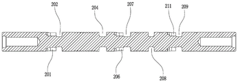
Preferably, the outer sides of the left end and the right end of the main valve core are respectively provided with a first annular groove and a second annular groove, and the first annular groove and the second annular groove are respectively matched with the left first oil storage cavity and the right first oil storage cavity; the edge of the inner wall of the left side of the first annular groove is provided with two first open grooves which are arranged diagonally, the edge of the inner wall of the right side of the first annular groove is provided with two second open grooves which are arranged diagonally, and the two second open grooves and the two first open grooves are mutually spaced and vertically distributed; the edge of the inner wall at the left side of the second annular groove is provided with two third open grooves which are arranged in opposite angles, the edge of the inner wall at the right side of the second annular groove is provided with two fourth open grooves which are arranged in opposite angles, the two fourth open grooves and the two third open grooves are mutually separated and vertically distributed, the outer side of the main valve core is also provided with a third annular groove, a fourth annular groove and a fifth annular groove from left to right in sequence, the third annular groove, the fourth annular groove and the fifth annular groove are all arranged between the first annular groove and the second annular groove and are respectively matched with the second oil storage cavity, the third oil storage cavity and a fourth oil storage cavity at the right side, the edge of the inner wall at the right side of the third annular groove is provided with two fifth open grooves which are arranged in opposite angles, and the edge of the inner wall at the left side of the fourth annular groove is provided with two sixth open grooves which are arranged in opposite angles, the two sixth opening grooves and the two fifth opening grooves are mutually spaced and vertically distributed.
Preferably, a driving cavity, a first oil supplementing cavity, a second oil supplementing cavity, a third oil supplementing cavity and an adjusting cavity which are distributed annularly from left to right are sequentially formed in the inner wall of the auxiliary valve hole, a fifth oil duct is formed between the first oil supplementing cavity and the third oil storing cavity, and a second through hole and a third through hole are respectively formed in the inner wall of the front side of the third oil supplementing cavity and the inner wall of the front side of the adjusting cavity.
Preferably, the oil supplementing assembly comprises an oil supplementing valve core, a first sealing plug, a second sealing plug and a check valve assembly, the first sealing plug and the second sealing plug are respectively inserted into the left end and the right end of the auxiliary valve hole in a threaded manner, the oil supplementing valve core is arranged in the auxiliary valve hole, can slide left and right and is arranged between the first sealing plug and the second sealing plug, and the check valve assembly is arranged inside the right end of the oil supplementing valve core.
Preferably, a sixth annular groove is formed in the outer side of the oil compensation valve core, the sixth annular groove is matched with the first oil compensation cavity, a fourth counter bore is formed in the left end of the oil compensation valve core, a fourth through hole is formed in the inner wall of the fourth counter bore, and the outer end of the fourth through hole is communicated with the bottom surface of the sixth annular groove.
Preferably, a fifth counter bore is formed in the right end of the oil compensating valve core, a tapered counter bore is formed in the center of the bottom surface of the fifth counter bore, a sixth counter bore is formed in the center of the bottom surface of the tapered counter bore, a seventh counter bore is formed in the center of the bottom surface of the sixth counter bore, an eighth counter bore is formed in the center of the bottom surface of the seventh counter bore, a fifth through hole is formed in the inner wall of the eighth counter bore, the outer end of the fifth through hole is communicated with the second oil compensating chamber, a plurality of sixth through holes which are distributed at equal angles in the circumferential direction are formed in the inner wall of the seventh counter bore, and the outer end of each sixth through hole is communicated with the third oil compensating chamber; and a seventh through hole is formed in the inner wall of the fifth counter bore, and the outer end of the seventh through hole is communicated with the adjusting cavity.
Preferably, the check valve assembly comprises a valve seat, a valve head and a spring, the valve seat is inserted and fixed in the fifth counterbore, the left end of the valve seat is inserted in the sixth counterbore, a convex column is formed outwards in the center of the left end of the valve seat, the convex column is inserted into the opening of the right end of the seventh counterbore, the valve head is concentrically arranged at the bottom of the seventh counterbore, the left end of the valve head is hermetically attached to the opening of the right end of the eighth counterbore, a certain distance is reserved between the outer wall of the valve head and the inner wall of the seventh counterbore, the spring is sleeved outside the convex column, and two ends of the spring respectively abut against the right end of the valve head and the left end of the valve seat.
Preferably, a first guide pillar is formed outwards in the center of the left end of the valve head, the first guide pillar is concentrically inserted into the eighth counterbore, and the outer wall of the first guide pillar is spaced from the inner wall of the eighth counterbore by a certain distance; and a second guide pillar is formed outwards in the center of the right end of the valve head and movably inserted into the convex pillar.
Preferably, a seventh annular groove is circumferentially distributed on the outer side of the valve seat, the inner end of the seventh through hole is communicated with the seventh annular groove, a first oil hole is formed in the seventh annular groove, a ninth counter bore is formed in the right end of the valve seat, and a second oil hole is formed between the bottom surface of the ninth counter bore and the first oil hole.
Compared with the prior art, the invention has the advantages that: according to the invention, the main valve core and the oil supplementing assembly are arranged in the same valve block, so that the structure is simplified, the movement and the installation are convenient, and the main valve core and the oil supplementing assembly form a mutually matched linkage mechanism in the same valve block, so that the deviation of the action time of the main valve core and the oil supplementing assembly is eliminated, and the control precision is improved to solve the problem of hysteresis in operation.
Drawings
FIG. 1 is a front sectional view of the present invention;
FIG. 2 is a rear sectional view of the valve block of the present invention;
FIG. 3 is a front right side structural view of the valve block of the present invention;
FIG. 4 is a top view block diagram of the main spool of the present invention;
FIG. 5 is a front cross-sectional block diagram of a main spool of the present invention;
fig. 6 is a front sectional view of the oil feed valve element according to the present invention.
Detailed Description
Unless defined otherwise, technical or scientific terms used herein shall have the ordinary meaning as understood by one of ordinary skill in the art to which this invention belongs. The use of "first," "second," and similar terms in the present application do not denote any order, quantity, or importance, but rather the terms are used to distinguish one element from another. The word "comprising" or "comprises", and the like, means that the element or item listed before the word covers the element or item listed after the word and its equivalents, but does not exclude other elements or items. The terms "connected" or "coupled" and the like are not restricted to physical or mechanical connections, but may include electrical connections, whether direct or indirect. "upper", "lower", "left", "right", and the like are used merely to indicate relative positional relationships, and when the absolute position of the object being described is changed, the relative positional relationships may also be changed accordingly.
To maintain the following description of the embodiments of the present invention clear and concise, a detailed description of known functions and known components of the invention have been omitted.
As shown in fig. 1 to 6, a pressure control valve includes a valve block 1, a main valve element 2 and an oil compensating assembly, which are disposed in the valve block 1; a main valve hole 122 and an auxiliary valve hole 108 which are transversely distributed are sequentially formed between the left side and the right side of the valve block 1 from top to bottom, the main valve core 2 is arranged in the main valve hole 122 and can slide left and right, and the oil supplementing assembly is arranged in the auxiliary valve hole 108; the upper side of the valve block 1 is provided with two first counter bores 101, correspondingly, the inner wall of the main valve hole 122 is provided with two first oil storage cavities 103 distributed annularly, a first oil duct 102 is respectively arranged between the two first oil storage cavities 103 and the bottom surfaces of the two first counter bores 101, the inner wall of the main valve hole 122 is further provided with a second oil storage cavity 121, a third oil storage cavity 106 and two fourth oil storage cavities 104, the two fourth oil storage cavities 104 are respectively arranged at the inner sides of the two first oil storage cavities 103, the second oil storage cavity 121 and the third oil storage cavity 106 are sequentially arranged between the two fourth oil storage cavities 104 from left to right, and a second oil duct 105 is arranged between the two fourth oil storage cavities 104; a first through hole 123 is formed in the inner wall of the front side of the second oil storage cavity 121, a fifth oil storage cavity 115 and a sixth oil storage cavity 117 are further formed in the inner wall of the main valve hole 122, the fifth oil storage cavity 115 and the sixth oil storage cavity 117 are respectively arranged on the outer sides of the left first oil storage cavity 103 and the right first oil storage cavity 103, a second counter bore 114 and a third counter bore 118 are formed in the front side of the valve block 1, the second counter bore 114 is arranged on the left side of the third counter bore 118, a third oil channel 116 is formed between the bottom surface of the second counter bore 114 and the inner wall of the fifth oil storage cavity 115, and a fourth oil channel 119 is formed between the bottom surface of the third counter bore 118 and the inner wall of the sixth oil storage cavity 117; a first annular groove 202 and a second annular groove 209 are respectively formed in the outer sides of the left end and the right end of the main valve element 2, and the first annular groove 202 and the second annular groove 209 are respectively matched with the left first oil storage cavity 103 and the right first oil storage cavity 103; the edge of the inner wall of the left side of the first annular groove 202 is provided with two first open grooves 201 which are arranged diagonally, the edge of the inner wall of the right side of the first annular groove 202 is provided with two second open grooves 203 which are arranged diagonally, and the two second open grooves 203 and the two first open grooves 201 are mutually spaced and vertically distributed; the edge of the inner wall at the left side of the second annular groove 209 is provided with two third opening grooves 211 which are arranged diagonally, the edge of the inner wall at the right side of the second annular groove 209 is provided with two fourth opening grooves 210 which are arranged diagonally, the two fourth opening grooves 210 and the two third opening grooves 211 are mutually separated and vertically distributed, the outer side of the main valve element 2 is also provided with a third annular groove 204, a fourth annular groove 207 and a fifth annular groove 208 from left to right in sequence, the third annular groove 204, the fourth annular groove 207 and the fifth annular groove 208 are all arranged between the first annular groove 202 and the second annular groove 209 and are respectively matched with the second oil storage cavity 121, the third oil storage cavity 106 and a fourth oil storage cavity 104 at the right side, the edge of the inner wall at the right side of the third annular groove 204 is provided with two fifth opening grooves 205 which are arranged diagonally, the edge of the inner wall at the left side of the fourth annular groove 207 is provided with two sixth opening grooves 206 which are arranged diagonally, the two sixth opening grooves 206 and the two fifth opening grooves 205 are spaced apart from each other and are vertically distributed.
The inner wall of the auxiliary valve hole 108 is sequentially provided with a driving cavity 109, a first oil supplementing cavity 110, a second oil supplementing cavity 113, a third oil supplementing cavity 111 and an adjusting cavity 112 which are distributed annularly from left to right, a fifth oil channel 107 is arranged between the first oil supplementing cavity 110 and the third oil storage cavity 106, and the inner walls of the front sides of the third oil supplementing cavity 111 and the adjusting cavity 112 are respectively provided with a second through hole 125 and a third through hole 126.
The oil supplementing assembly comprises an oil supplementing valve core 3, a first sealing plug 6, a second sealing plug 5 and a check valve assembly, wherein the first sealing plug 6 and the second sealing plug 5 are respectively inserted and screwed inside the left end and the right end of the auxiliary valve hole 108, the oil supplementing valve core 3 is arranged in the auxiliary valve hole 108 and can slide left and right and is arranged between the first sealing plug 6 and the second sealing plug 5, the check valve assembly is arranged inside the right end of the oil supplementing valve core 3, a sixth annular groove 31 is formed in the outer side of the oil supplementing valve core 3, the sixth annular groove 31 is matched with the first oil supplementing cavity 110, a fourth counter bore 37 is formed in the left end of the oil supplementing valve core 3, a fourth through hole 38 is formed in the inner wall of the fourth counter bore 37, the outer end of the fourth through hole 38 is communicated with the bottom surface of the sixth annular groove 31, a fifth counter bore 32 is formed in the right end of the oil supplementing valve core 3, a conical counter bore 34 is formed in the center of the bottom surface of the fifth counter bore 32, a sixth counter bore 310 is formed in the center of the bottom surface of the conical counter bore 34, a seventh counter bore 311 is formed in the center of the bottom surface of the sixth counter bore 310, an eighth counter bore 33 is formed in the center of the bottom surface of the seventh counter bore 311, a fifth through hole 39 is formed in the inner wall of the eighth counter bore 33, the outer end of the fifth through hole 39 is communicated with the second oil replenishing cavity 113, a plurality of sixth through holes 35 which are distributed at equal angles in the circumferential direction are formed in the inner wall of the seventh counter bore 311, and the outer end of each sixth through hole 35 is communicated with the third oil replenishing cavity 111; the inner wall of the fifth counter bore 32 is provided with a seventh through hole 36, and the outer end of the seventh through hole 36 is communicated with the adjusting cavity 112.
The check valve assembly comprises a valve seat 7, a valve head 4 and a spring 8, the valve seat 7 is inserted and fixed in the fifth counterbore 32, the left end of the valve seat 7 is inserted in the sixth counterbore 310, a convex column 72 is outwards formed in the center of the left end of the valve seat 7, the convex column 72 is inserted in the right end opening of the seventh counterbore 311, the valve head 4 is concentrically arranged at the bottom of the seventh counterbore 311, the left end of the valve head 4 is hermetically attached to the right end opening of the eighth counterbore 33, the outer wall of the valve head 4 is spaced from the inner wall of the seventh counterbore 311 by a certain distance, a first guide column 41 is outwards formed in the center of the left end of the valve head 4, the first guide column 41 is concentrically inserted in the eighth counterbore 33, and the outer wall of the first guide column 41 is spaced from the inner wall of the eighth counterbore 33 by a certain distance; a second guide post 42 is formed outwards in the center of the right end of the valve head 4, the second guide post 42 is movably inserted into the convex post 72, the spring 8 is sleeved outside the convex post 72, and two ends of the spring 8 respectively abut against the right end of the valve head 4 and the left end of the valve seat 7; the outer side of the valve seat 7 is provided with a seventh annular groove 71 which is annularly distributed, and the inner end of the seventh through hole 36 is communicated with the seventh annular groove 71.
The seventh annular groove 71 is opened with a first oil hole 73, the right end of the valve seat 7 is opened with a ninth counterbore 75, and a second oil hole 74 is opened between the bottom surface of the ninth counterbore 75 and the first oil hole 73.
When in use: two streams of oil are respectively led into two first oil storage chambers 103 through two first counter bores 101 and two first oil channels 102, the main valve element 2 is driven to move to the right, so that two first opening grooves 201 move into one first oil storage chamber 103 on the left side, two second opening grooves 203 move into one fourth oil storage chamber 104 on the left side, two third opening grooves 211 move into one first oil storage chamber 103 on the right side, two fourth opening grooves 210 move into a sixth oil storage chamber 117, a fifth annular groove 208 moves between one first oil storage chamber 103 on the right side and one fourth oil storage chamber 104 on the right side at the moment, a stream of oil on the left side flows into a first annular groove 202 through the two first opening grooves 201, then flows into one fourth oil storage chamber 104 on the left side through the two second opening grooves 203, then flows into one fourth oil storage chamber 104 on the right side through the second oil channel 105, and then flows into one first oil storage chamber 103 on the right side through the fifth annular groove 208, then, the oil is merged with a right oil flow and flows into the second annular groove 209 through the two third opening grooves 211, then flows into the sixth oil storage chamber 117 through the two fourth opening grooves 210, and finally is output outwards through the fourth oil passage 119 and the third counter bore 118.
Driving main spool 2 to move left until two first opening grooves 201 move into fifth reservoir 115, at which time two second opening grooves 203 move into one first reservoir 103 on the left, two third opening grooves 211 move into one fourth reservoir 104 on the right, two fourth opening grooves 210 move into one first reservoir 103 on the right, third annular groove 204 move into one fourth reservoir 104 on the left, two fifth opening grooves 205 move into second reservoir 121, and two sixth opening grooves 206 move into third reservoir 106; a left strand of oil flows into the first annular groove 202 through the two second opening grooves 203, flows into the fifth oil storage chamber 115 through the two first opening grooves 201, and is finally output outwards through the third oil passage 116 and the second counter bore 114; at this time, a right strand of oil flows into the second annular groove 209 through the two fourth opening grooves 210, flows into the right fourth oil storage chamber 104 through the two third opening grooves 211, flows into the left fourth oil storage chamber 104 through the second oil passage 105, flows into the second oil storage chamber 121 through the third annular groove 204, flows into the fourth annular groove 207 through the two fifth opening grooves 205, flows into the third oil storage chamber 106 through the two sixth opening grooves 206, and flows into the first oil compensation chamber 110 through the fifth oil passage 107.
The oil in the first oil supply chamber 110 flows into the driving chamber 109 through the fourth through hole 38 and the fourth counterbore 37 to push the oil supply valve core 3 to move to the right, so that the sixth annular groove 31 moves between the first oil supply chamber 110 and the second oil supply chamber 113, the oil in the first oil supply chamber 110 flows into the second oil supply chamber 113 through the sixth annular groove 31, then flows into the eighth counterbore 33 through the fifth through hole 39 to push the valve head 4 to move to the right, and when the left end of the valve head 4 leaves the right end opening of the eighth counterbore 33, the oil in the eighth counterbore 33 enters the seventh counterbore 311, flows into the third oil supply chamber 111 through the sixth through holes 35, and finally is output to the outside through the second through hole 125.
Another oil is introduced into the adjusting cavity 112 through the third through hole 126, flows into the fifth counterbore 32 through the seventh through hole 36, enters the second oil hole 74 through both ends of the first oil hole 73, and flows into the right end of the sub-valve hole 108 through the ninth counterbore 75, so that the oil supplement valve element 3 is pushed leftward, the size of the gap between the sixth annular groove 31 and the second oil supplement cavity 113 is reduced, and the flow rate is adjusted.
According to the invention, the main valve core and the oil supplementing assembly are arranged in the same valve block, so that the structure is simplified, the movement and the installation are convenient, and the main valve core and the oil supplementing assembly form a mutually matched linkage mechanism in the same valve block, so that the deviation of the action time of the main valve core and the oil supplementing assembly is eliminated, and the control precision is improved to solve the problem of hysteresis in operation.
Finally, it should be noted that: the above examples are only intended to illustrate the technical solution of the present invention, but not to limit it; although the present invention has been described in detail with reference to the foregoing embodiments, it will be understood by those skilled in the art that various changes in the embodiments and modifications thereof may be made, and equivalents may be substituted for elements thereof; and the modifications or the substitutions do not make the essence of the corresponding technical solutions depart from the spirit and scope of the technical solutions of the embodiments of the present invention.
Claims (9)
Priority Applications (1)
| Application Number | Priority Date | Filing Date | Title |
|---|---|---|---|
| CN202010961547.3A CN114183421A (en) | 2020-09-14 | 2020-09-14 | Pressure control valve |
Applications Claiming Priority (1)
| Application Number | Priority Date | Filing Date | Title |
|---|---|---|---|
| CN202010961547.3A CN114183421A (en) | 2020-09-14 | 2020-09-14 | Pressure control valve |
Publications (1)
| Publication Number | Publication Date |
|---|---|
| CN114183421A true CN114183421A (en) | 2022-03-15 |
Family
ID=80539002
Family Applications (1)
| Application Number | Title | Priority Date | Filing Date |
|---|---|---|---|
| CN202010961547.3A Pending CN114183421A (en) | 2020-09-14 | 2020-09-14 | Pressure control valve |
Country Status (1)
| Country | Link |
|---|---|
| CN (1) | CN114183421A (en) |
Citations (8)
| Publication number | Priority date | Publication date | Assignee | Title |
|---|---|---|---|---|
| CN203176034U (en) * | 2013-02-04 | 2013-09-04 | 陕西航天动力高科技股份有限公司 | Volume changeable compact type overload oil supplement valve |
| US20130340851A1 (en) * | 2012-06-22 | 2013-12-26 | Kevin T. Peel | Flow control valve |
| CN203477451U (en) * | 2013-09-25 | 2014-03-12 | 北京汽车动力总成有限公司 | Pressure control valve |
| CN203655769U (en) * | 2014-01-22 | 2014-06-18 | 宁波市镇海华力液压机电有限公司 | Overflow valve |
| US20160223091A1 (en) * | 2015-01-29 | 2016-08-04 | Poclain Hydraulics Industrie | Flow control valve |
| WO2017168956A1 (en) * | 2016-03-30 | 2017-10-05 | 日立建機株式会社 | Pressure reducing valve unit |
| CN108302078A (en) * | 2018-03-19 | 2018-07-20 | 安徽博流体传动股份有限公司 | Remote-control pressure control valve |
| CN212377006U (en) * | 2020-09-14 | 2021-01-19 | 宁波佳缘海沃机械有限公司 | Pressure control valve |
-
2020
- 2020-09-14 CN CN202010961547.3A patent/CN114183421A/en active Pending
Patent Citations (8)
| Publication number | Priority date | Publication date | Assignee | Title |
|---|---|---|---|---|
| US20130340851A1 (en) * | 2012-06-22 | 2013-12-26 | Kevin T. Peel | Flow control valve |
| CN203176034U (en) * | 2013-02-04 | 2013-09-04 | 陕西航天动力高科技股份有限公司 | Volume changeable compact type overload oil supplement valve |
| CN203477451U (en) * | 2013-09-25 | 2014-03-12 | 北京汽车动力总成有限公司 | Pressure control valve |
| CN203655769U (en) * | 2014-01-22 | 2014-06-18 | 宁波市镇海华力液压机电有限公司 | Overflow valve |
| US20160223091A1 (en) * | 2015-01-29 | 2016-08-04 | Poclain Hydraulics Industrie | Flow control valve |
| WO2017168956A1 (en) * | 2016-03-30 | 2017-10-05 | 日立建機株式会社 | Pressure reducing valve unit |
| CN108302078A (en) * | 2018-03-19 | 2018-07-20 | 安徽博流体传动股份有限公司 | Remote-control pressure control valve |
| CN212377006U (en) * | 2020-09-14 | 2021-01-19 | 宁波佳缘海沃机械有限公司 | Pressure control valve |
Similar Documents
| Publication | Publication Date | Title |
|---|---|---|
| US9644760B2 (en) | Damping valve | |
| US5109886A (en) | Fluid pressure controller | |
| US9453518B2 (en) | Proportional pressure-regulating valve | |
| US9599183B2 (en) | Damping valve | |
| US10132378B2 (en) | Damping valve | |
| CN212377006U (en) | Pressure control valve | |
| CN105952705A (en) | Balance valve | |
| WO2023077630A1 (en) | Reversing valve | |
| CN212564588U (en) | Pilot-operated type dynamic differential pressure balance valve | |
| JPH11268629A (en) | Master cylinder | |
| CN114183421A (en) | Pressure control valve | |
| CN105443802A (en) | Three-port microvalve with improved sealing mechanism | |
| CN108533763B (en) | Stop valve with controllable opening and closing speed | |
| CN111853309A (en) | Pilot-operated type dynamic differential pressure balance valve | |
| CN102235540A (en) | Solenoid spool valve | |
| CN103867511B (en) | Flow control valve | |
| CN108661966B (en) | Plug-in type pressure compensation valve | |
| JP2008014492A (en) | Cartridge valve assembly | |
| CN116201781B (en) | Hydraulic systems, construction machinery and pressure compensation valves | |
| CN219062110U (en) | Valve back compensation multiway valve and hydraulic driving system | |
| CN212657075U (en) | Winch balance valve | |
| CN214577994U (en) | Load-sensitive multi-way valve reversing linkage | |
| CN212273180U (en) | Pilot-operated type dynamic differential pressure balance valve | |
| JP4986884B2 (en) | Load sensing valve | |
| CN107725517A (en) | A kind of proportional flow magnetic valve |
Legal Events
| Date | Code | Title | Description |
|---|---|---|---|
| PB01 | Publication | ||
| PB01 | Publication | ||
| SE01 | Entry into force of request for substantive examination | ||
| SE01 | Entry into force of request for substantive examination | ||
| WD01 | Invention patent application deemed withdrawn after publication | ||
| WD01 | Invention patent application deemed withdrawn after publication |
Application publication date: 20220315 |