Detailed Description
The technical solutions in the embodiments of the present application will be clearly described below with reference to the drawings in the embodiments of the present application. In the present application, "a plurality" means two or more.
Fig. 1 illustrates a schematic diagram of a 5G roaming communication system in an LBO scenario according to an embodiment of the present application. In the 5G mobile network architecture, the control plane function and the forwarding plane function of the mobile gateway are decoupled, and the separated control plane function is merged with a Mobility Management Entity (MME) of a third generation partnership project (3 GPP) conventional control network element to form a unified control plane (control plane). A User Plane Function (UPF) network element can implement a Serving Gateway (SGW) and a packet data network gateway (PGW) User plane functions (SGW-U and PGW-U). Further, the unified control plane network element may be decomposed into an access and mobility management function (AMF) network element and a Session Management Function (SMF) network element.
As shown in fig. 1, the communication system includes at least User Equipment (UE) 101, network devices in the VPLMN, and network devices in the HPLMN. The network device in the VPLMN and the network device in the HPLMN respectively include a Policy Control Function (PCF) network element 105 and a PCF network element 107.
The user equipment 101 involved in the present system is not limited to the 5G network, and includes: the system comprises a mobile phone, an internet of things device, an intelligent household device, an industrial control device, a vehicle device and the like. The User Equipment may also be referred to as a Terminal Equipment (Terminal Equipment), a Mobile Station (Mobile Station), a Mobile Station (Mobile), a Remote Station (Remote Station), a Remote Terminal (Remote Terminal), an Access Terminal (Access Terminal), a User Equipment (User Terminal), and a User Agent (User Agent), which are not limited herein. The user device may also be an automobile in Vehicle-to-Vehicle (V2V) communication, a machine in machine-to-machine communication, or the like.
The PCF network elements involved in the system (e.g., PCF network element 105, PCF network element 107) contain functions for policy control. Optionally, the PCF network element further supports a unified policy framework to manage the network behavior. Optionally, the PCF network element may also have access to subscription information related to the policy in the unified data repository. A PCF network element may also be referred to as a PCF entity or PCF device.
Optionally, the Network device in the VPLMN further includes a Radio Access Network (RAN) device 102 and an AMF Network element 103. The AMF network element 103 may be responsible for attachment of a terminal device, mobility management, tracking area update process, and the like. The AMF network element may also be referred to as an AMF device or an AMF entity.
The RAN apparatus 102 is a means for providing wireless communication functions for the UE 101. The RAN equipment may include various forms of base stations, such as: macro base stations, micro base stations (also referred to as small stations), relay stations, access points, etc. In systems using different radio access technologies, names of devices having a base station function may be different, for example, in an LTE system, the device is called an evolved node B (eNB or eNodeB), and in a third generation (3G) system, the device is called a node B (node B). In a new generation system, called gnb (gnnodeb).
In addition, the Network device in the VPLMN further includes a Network Slice Selection Function (NSSF) Network element 104 in the VPLMN. The NSSF network element 104 can select a network slice for the user equipment. The NSSF network element may also be referred to as an NSSF device or an NSSF entity.
Optionally, the network device in the HPLMN further includes a Unified Data Management (UDM) network element 106. The UDM network element 106 is able to store subscription data for the user. For example, the subscription data of the user includes subscription data related to mobility management and subscription data related to session management. The UDM network element may also be referred to as a UDM device or a UPF entity.
In the 5G roaming communication system in the LBO scenario shown in fig. 1, the UE101 registers in the VPLMN, so that the service of the VPLMN can be accessed. During the registration process, the UE101 may select an initial AMF device 103 through the RAN device 102, and the initial AMF device 103 may request the UDM network element 106 of the HPLMN to obtain subscription data of the UE 101. If the original AMF device 103 cannot provide service to the UE101, the original AMF device 103 requests the NSSF network element 104 to select another AMF device that can meet the user's requirements to provide service to the user. The PCF network element 105 in the VPLMN may request the PCF network element 107 in the HPLMN to obtain the URSP of the HPLMN, then generate the URSP of the VPLMN and send to the UE 101. When the UE101 initiates the APP service in the VPLMN, a session is established according to the URSP of the VPLMN.
The network elements may be network elements implemented on dedicated hardware, or may be software instances running on dedicated hardware, or may be instances of virtualized functions on a suitable platform, for example, the virtualized platform may be a cloud platform.
In addition, the embodiment of the application can also be applied to other communication technologies facing the future. The network architecture and the service scenario described in this application are for more clearly illustrating the technical solution of this application, and do not constitute a limitation to the technical solution provided in this application, and it can be known by those skilled in the art that the technical solution provided in this application is also applicable to similar technical problems along with the evolution of the network architecture and the appearance of new service scenarios.
The following takes the 5G roaming communication system under the LBO scenario shown in fig. 1 as an example, and details the technical solution of the present application through some embodiments. The following several embodiments may be combined with each other and may not be described in detail in some embodiments for the same or similar concepts or processes.
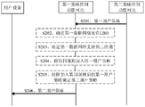
Fig. 2 is a flowchart of a method for obtaining a user policy according to an embodiment of the present disclosure. The method can be used for the user equipment to obtain the user strategy of the VPLMN from the strategy control function network element of the VPLMN. As shown in fig. 2, the method may include:
s201, the second policy control function network element of the HPLMN sends the first user policy of the HPLMN to the first policy control function network element of the VPLMN. Correspondingly, the first policy control function network element of the VPLMN receives the first user policy of the HPLMN from the second policy control function network element of the HPLMN. Wherein the first user policy includes a first rule. The first rule is used to indicate an association between first network slice identification information, a first application, and first data network identification information, the first data network identification information being used to identify a first data network, the first data network allowing LBO and supporting the first application and a second application.
For example, the first policy control function network element is PCF network element 105 of VPLMN in fig. 1, and the second policy control function network element is PCF network element 107 of HPLMN in fig. 1. The first user policy may be a first URSP. The first network slice identification information may be a first S-NSSAI. The first data network may be a first DN. The first data network identification information for identifying the first data network may be a first Data Network Name (DNN).
For example, the first URSP is shown in table 1. In the example of table 1: the DNN corresponding to the network slice identified as S-NSSAI1 is DNN1, wherein DNN1 is the identification of DN1, and DN1 supports APP 1. The first URSP comprises a first rule for indicating an association between S-NSSAI1, APP1 and DNN 1. When the user equipment starts APP1, the S-NSSAI corresponding to APP1 is determined to be S-NSSAI1 according to the first URSP, then a session establishment flow is initiated according to the S-NSSAI1 identification, and further communication connection between the user equipment and DN1 is established. In addition, DN1 allows LBO, and DN1 also supports APP 2.
TABLE 1
| APP
|
S-NSSAI
|
DNN
|
| APP 1
|
S-NSSAI 1
|
DNN 1 |
For example, when the second PCF network element receives a request message for acquiring the first URSP sent by the first PCF network element, or when the first PCF invokes to acquire the first URSP service, the second PCF network element sends the first URSP to the first PCF network element. The process by which the first PCF network element obtains the first URSP from the second PCF network element may be further described in conjunction with fig. 5 or fig. 6.
S206, the first strategy control function network element sends a second user strategy to the user equipment. Correspondingly, the user equipment receives the second user policy from the first policy control function network element. The second user policy includes a second rule and a third rule, the second rule is used for indicating association among the second network slice identification information, the first application and the first data network identification information, and the third rule is used for indicating association among the second network slice identification information, the second application and the first data network identification information.
The user equipment is, for example, the UE101 in FIG. 1. The second user policy may be a second URSP. The second network slice identification information may be a second S-NSSAI.
It should be noted that, the first policy control function network element may first send the second user policy to the access and mobility management network element (e.g., the AMF network element 103 in fig. 1), and the access and mobility management network element forwards the second user policy to the user equipment.
According to the method of the embodiment of the invention, the second URSP of the VPLMN, which is acquired by the user equipment, includes information of APPs which do not exist in the first URSP of the HPLMN but can be used in an LBO scenario of the VPLMN, such as a third rule associated with the second application. The user equipment can use more APP services in the LBO scene of the VPLMN according to the second URSP obtained in the scheme, so that the user experience is improved.
For example, the HPLMN deploys a network slice with a network slice type of S-NSSAI1, and the first URSP of the HPLMN includes a correspondence relationship between APP1, S-NSSAI1, and DNN 1. So in the HPLMN, the user equipment can establish a session connection with the APP1 server. In the prior art, the second URSP in the VPLMN obtained by the user equipment is obtained according to the first URSP in the HPLMN, so the second URSP of the VPLMN includes the corresponding relationship associated with APP1 and DNN 1. Thus, in VPLMN, the user equipment can still only establish a session connection with the APP1 server, that is, only use APP 1. However, in VPLMN, DN1 is LBO-enabled, and APP2 server is also included in DN1, so in VPLMN, APP2 server can essentially provide APP2 service for user equipment. However, since the second URSP of the VPLMN in the prior art does not have the association corresponding to APP2, the user equipment cannot use APP2, thereby reducing the service experience of the user. However, according to the embodiment of the present application, the association corresponding to APP2 is included in the second URSP of the VPLMN. Thus, the user device may use the APP2, improving the user experience.
The following will describe in detail both aspects from the point that the first S-NSSAI in the second URSP of VPMN is the same as or corresponds to the second S-NSSAI in the first URSP of HPMN.
For example, when the second S-NSSAI is the same as the first S-NSSAI, the second rule in the second URSP is the same as the first rule in the first URSP. Since the DN identified by DNN1 allows LBO, and this DN1 supports APP2 in addition to APP 1. Thus, the second URSP also includes associations between S-NSSAI1, APP2 and DNN1, as shown in table 2. The association between S-NSSAI1, APP2, and DNN1 is the third rule in the second URSP.
TABLE 2
When the second S-NSSAI corresponds to the first S-NSSAI, the second rule in the second URSP corresponds to the first rule of the first URSP. For example, the first S-NSSAI is S-NSSAI1 described above, and the second S-NSSAI corresponding to S-NSSAI1 is eMBB. Thus, the second URSP includes the association between APP1, eMBB, and DNN1 (i.e., the second rule described above). Since the DN identified by DNN1 allows LBO, and this DN1 supports APP2 in addition to APP 1. Thus, the second URSP also includes an association (i.e., a third rule) between APP2, eMBB, and DNN1, as shown in table 3. The determination of the second URSP may be further described in conjunction with fig. 3.
TABLE 3
| APP
|
S-NSSAI
| DNN
|
| APP |
| 1
|
eMBB
| DNN | 1
|
| APP 2
|
eMBB
| DNN | 1 |
For example, prior to step S206, the first policy control function network element may determine the second URSP through steps S202 to S205. Steps S202 and S203 are optional steps, that is, the first policy control function network element may also determine the first DN and the second application in other manners, which is not limited in this embodiment.
S202, the first policy control function network element determines that the first data network allows LBO.
For example, after receiving the first URSP from the second policy control function network element, the first policy control function network element determines a DN, such as the first DN, of the first URSP, which allows LBO, according to the corresponding relationship between DNN and LBO in the first policy control function network element. For example, the correspondence between DNN and LBO may be configured in advance in the first policy control function network element by the network management system.
In one possible implementation, the correspondence between DNN and LBO may be represented in the form of LBO-enabled DNN, for example:
DNN allowed LBO: DNN1, DNN 3, …
The above examples show that: both DN1 identified by DNN1 and DN 3 identified by DNN 3 allow LBO.
In another possible implementation manner, the correspondence between DNN and LBO may also be represented in a table form, as shown in table 4. In the example of table 4, the correspondence between DNN and LBO includes: DNN1 identifies a DN1 that is LBO-enabled and DNN 2 identifies a DN 2 that is LBO-disabled.
TABLE 4
| DNN
|
Enabling/disabling LBO
|
| DNN |
| 1
|
Allow for
|
| DNN 2
|
Inhibit |
Optionally, the first policy control function network element may further determine that the second DN is not an LBO-allowed DN.
For example, the first URSP may further include a second DN that disables LBO. For example, a fifth rule for indicating an association between a third S-NSSAI, a third application, and a second DNN is also included in the first URSP. Wherein the second DNN is used to identify a second DN, the second DN supporting a third application. For example, if the third S-NSSAI is S-NSSAI 2, the third application is APP 3, and the second DNN is DNN 2, the first URSP including the fifth rule may be as shown in table 5. The first URSP comprises a fifth rule for indicating an association between S-NSSAI 2, APP 3 and DNN 2.
TABLE 5
| APP
|
S-NSSAI
|
DNN
|
| APP 1
|
S-NSSAI 1
|
DNN 1
|
| APP 3
|
S-NSSAI 2
|
DNN 2 |
It should be noted that the first rule and the fifth rule differ in that DN1 identified by DNN1 in the first rule is a LBO-enabled DN, and DN 2 identified by DNN 2 in the fifth rule is not a LBO-enabled DN, or DN 2 is a LBO-disabled DN.
S203, the first policy control function network element determines that the first data network supports the second application.
For example, after the first policy control function network element determines the first DN allowing LBO through step S202, APP supported by the first DN, e.g., the first application and the second application, is determined according to a corresponding relationship between DNN and APP in the first policy control function network element. Further, the first policy control function network element determines APPs, such as the second application, not involved in the first URSP from the APPs supported by the first DN. For example, the correspondence between DNN and APP may be configured in advance in the first policy control function network element through the network management system. For example, the correspondence relationship is shown in table 6. In the example of table 6: DN1 corresponding to DNN1 supports APP1 and APP 2. As can be seen from table 1 above, the first URSP includes the association between S-NSSAI1, APP1 and DNN1, but the first URSP does not include APP 2. The first policy control function network element may determine that the second application that is still supported by the first DN is APP 2. That is, the user equipment cannot use APP2 in the HPLMN, but the user equipment can use APP2 in the LBO scenario of the VPLMN.
TABLE 6
| DNN
| APP
|
| DNN |
| 1
|
APP 1,APP 2 |
Optionally, when the first URSP further includes the above fifth rule, since the DN 2 identified by DNN 2 in the fifth rule is not a DN allowing LBO, step S203 and subsequent S204 and S205 do not need to be executed.
And S204, the first policy control function network element adds a fourth rule to the first user policy, wherein the fourth rule comprises the association among the first network slice identification information, the second application and the first data network identification information.
For example, in a first rule, the first S-NSSAI associated with the first DNN (DNN 1) is S-NSSAI 1. In addition, the second application supported by the DN identified by the DNN determined in step S203 is APP 2. Therefore, the fourth rule includes an association between S-NSSAI1, APP2, and the first DNN. In combination with the first URSP shown in table 1, the first URSP after adding the fourth rule may be as shown in table 2.
Optionally, when the first URSP further includes the fifth rule, the first URSP after adding the fourth rule may be as shown in table 7, and details are not described here.
TABLE 7
| APP
|
S-NSSAI
|
DNN
|
| APP 1
|
S-NSSAI 1
|
DNN 1
|
| APP 2
|
S-NSSAI 1
|
DNN 1
|
| APP 3
|
S-NSSAI 2
|
DNN 2 |
And S205, the first policy control function network element determines a second user policy according to the first user policy added with the fourth rule.
Optionally, when the corresponding second S-NSSAI of DNN1 in VPLMN is the same as the first S-NSSAI in HPLMN, the second URSP is the first rsp after the fourth rule is added. For example, the second URSP may be as shown in table 2, the second URSP including a second rule indicating an association between the second S-NSSAI, the first APP, and the first DNN, and a third rule indicating an association between the second S-NSSAI, the second APP, and the first DNN.
Optionally, when the first URSP includes a second DN that prohibits LBO and DNN 2 has a third S-NSSAI in VPLMN that is the same as a fourth S-NSSAI in HPLMN, the second URSP may be as shown in table 7, and the second URSP further includes a sixth rule indicating an association between the fourth S-NSSAI, the third APP, and the second DNN. That is, the above-described fifth rule and sixth rule are the same.
Thereby, the first policy control function network element determines the second URSP.
Optionally, when the S-NSSAI corresponding to DNN1 in VPLMN corresponds to the first S-NSSAI in HPLMN, step 205 includes: the first policy control function network element obtains a mapping relationship between the S-NSSAI in the VPLMN and the S-NSSAI in the HPLMN, and determines the second user policy according to the mapping relationship and the first user policy after adding the fourth rule, which may be further described with reference to fig. 3.
Therefore, by the above scheme, the second URSP determined by the first policy control function network element includes information of APPs that can be used in an LBO scenario of the VPLMN. The user equipment can use the APP service supported in the LBO scene of the VPLMN according to the second URSP obtained in the scheme.
Fig. 3 is a flowchart of another method for obtaining a user policy according to an embodiment of the present disclosure. The method can be used for the user equipment to obtain the user strategy scenario of the VPLMN from the strategy control function network element of the VPLMN when the S-NSSAI in the VPLMN corresponds to the S-NSSAI in the HPLMN. In this scenario, the policy control function network element of the VPLMN generates the second URSP in a mapping manner. As shown in fig. 3, the method may include:
step S301 may refer to the description of S201 in fig. 2, and step S307 may refer to the description of S206 in fig. 2, which is not repeated herein.
For example, before step S307, the first policy control function network element may also determine the second URSP through steps S302 to S306. Steps S302 to S304 can refer to the descriptions of S202 to S204 in fig. 2, and are not described herein again.
Prior to step S307, the first policy control function network element may perform steps S305 and S306 as follows.
S305, the first policy control function network element receives the first mapping relationship between the first network slice identification information and the second network slice identification information from the access and mobility management function network element of the VPLMN. The first mapping relationship may be used for generation of a second user policy.
For example, the mobility management function network element is the AMF network element 103 in fig. 1. The first mapping between the first S-NSSAI and the second S-NSSAI may be generated by a network slice selection function network element (e.g., NSSF network element 104 in fig. 1) according to a roaming agreement between the VPLMN and the HPLMN and provided to the AMF network element. Alternatively, the first mapping relationship between the first S-NSSAI and the second S-NSSAI may also be generated by the AMF network element according to the roaming agreement. For example, the roaming Agreement may be a Service Level Agreement (SLA).
Different operators can deploy different types of network slices, and different types of network slices can be identified by standard S-NSSAI or specific S-NSSAI. The standard S-NSSAI is an S-NSSAI that can be recognized by operators, for example, three network slice types that are already specified in the current third generation partnership project (3 GPP) standard, enhanced Mobile Broadband (eMBB), ultra-reliable low-latency communication (URLLC), and massive internet of things (MIoT). The network slice identified by the specific S-NSSAI is not necessarily recognized by all operators, and only the operator that deploys the network slice identified by the S-NSSAI recognizes the specific S-NSSAI. For example, network slice types other than the three specified in the above-mentioned 3GPP standard may be considered as being of a unique type, such as vehicle-to-electrical (V2X).
Through the mapping relation between S-NSSAI, four ways of mapping can be realized: a mapping of a standard S-NSSAI to another standard S-NSSAI, or a mapping of a unique S-NSSAI to a standard S-NSSAI, or a mapping of a standard S-NSSAI to a unique S-NSSAI, or a mapping of a unique S-NSSAI to another unique S-NSSAI.
And S306, the first policy control function network element maps the first network slice identification information in the first user policy added with the fourth rule into second network slice identification information according to the first mapping relation, and generates a second user policy.
The following describes steps S305 and S306 in detail for the above four mapping scenarios.
The first method comprises the following steps:
the first S-NSSAI and the second S-NSSAI are both standard S-NSSAIs. For example, to implement load balancing, the NSSF network element generates a mapping relationship from a first S-NSSAI to a second S-NSSAI.
For example, the first mapping relationship may be as shown in table 8. In table 8, the first S-NSSAI is eMBB in HPLMN, the second S-NSSAI is MIoT in VPLMN, and the first mapping relationship is that eMBB corresponds to MIoT.
TABLE 8
| First S-NSSAI
|
Second S-NSSAI
|
| eMBB
|
MIoT |
In the first mapping relationship, the type of the network slice corresponding to the APP in the first URSP is the first S-NSSAI, and since the load of the network slice corresponding to the first S-NSSAI in the VPLMN is too large, in order to implement load balancing, the NSSF network element maps the first S-NSSAI to the second S-NSSAI, so that the user equipment establishes a session through the network slice corresponding to the second S-NSSAI. For example, in the scenario corresponding to table 8, the user equipment carries an S-NSSAI request identifying an eMBB slice type to establish a session, but the network slice load of the eMBB type in the VPLMN is too large, so the NSSF network element maps the eMBB identifier to an MIoT identifier, so that the user equipment uses the network slice of the MIoT type to establish a session when initiating an APP, where the first mapping relationship is: S-NSSAI of eMBB slice type corresponds to S-NSSAI of MIoT slice type.
In the first mapping manner, the specific manner in which the first policy control function network element executes step S306 to generate the second URSP is as follows:
for example, the first URSP after adding the fourth rule is shown in table 9. In the example of table 9, the DNN corresponding to the network slice identified as eMBB is DNN1, where DNN1 is the identification of DN1, and DN1 supports APP1 and APP 2. The first rule is used for indicating the association among the eMBB, the APP1 and the DNN1, and the fourth rule is used for indicating the association among the eMBB, the APP2 and the DNN 1.
TABLE 9
| APP
|
S-NSSAI
| DNN
|
| APP |
| 1
|
eMBB
| DNN | 1
|
| APP 2
|
eMBB
| DNN | 1 |
As can be seen from the mapping in table 8, the eMBB in the HPLMN corresponds to the MIoT in the VPLMN, so the first S-NSSAI (e.g., eMBB) may be mapped to the second S-NSSAI (e.g., MIoT) to generate the second URSP. The generated second URSP may be as shown in table 10. In the example of table 10: the second URSP comprises a second rule indicating an association between the second S-NSSAI (e.g. MIoT), the first application (e.g. APP 1) and the first DNN (e.g. DNN 1) and a third rule indicating an association between the second S-NSSAI (e.g. MIoT), the second application (e.g. APP 2) and the first DNN (e.g. DNN 1).
Watch 10
| APP
|
S-NSSAI
| DNN
|
| APP |
| 1
|
MIoT
| DNN | 1
|
| APP 2
|
MIoT
| DNN | 1 |
And the second method comprises the following steps:
and when the first S-NSSAI is the S-NSSAI specific to the HPLMN and the second S-NSSAI is the standard S-NSSAI, the NSSF network element generates a first mapping relation between the first S-NSSAI and the standard S-NSSAI according to a roaming protocol between the VPLMN and the HPLMN.
For example, the first mapping relationship may be as shown in table 11. In table 11, the first S-NSSAI is S-NSSAI1 in HPLMN, the second S-NSSAI is URLLC in VPLMN, and the first mapping relationship is that S-NSSAI1 corresponds to URLLC.
TABLE 11
| First S-NSSAI
|
Second S-NSSAI
|
| S-NSSAI 1
|
URLLC |
In the second mapping manner, the specific manner in which the first policy control function network element executes step S306 to generate the second URSP is as follows:
for example, the first URSP after adding the fourth rule is shown in table 2. In the example of table 2, the DNN corresponding to the network slice identified as S-NSSAI1 is DNN1, where DNN1 is the identification of DN1, and DN1 supports APP1 and APP 2.
As can be obtained from the mapping relationship in table 11, S-NSSAI1 in HPLMN corresponds to URLLC in VPLMN, so a first S-NSSAI (e.g., S-NSSAI 1) can be mapped to a second S-NSSAI (e.g., URLLC), thereby generating a second URSP. The generated second URSP may be as shown in table 12. In the example of table 12: the second URSP comprises a second rule indicating an association between the second S-NSSAI (e.g. URLLC), the first application (e.g. APP 1) and the first DNN (e.g. DNN 1) and a third rule indicating an association between the second S-NSSAI (e.g. URLLC), the second application (e.g. APP 2) and the first DNN (e.g. DNN 1).
TABLE 12
| APP
|
S-NSSAI
| DNN
|
| APP |
| 1
|
URLLC
| DNN | 1
|
| APP 2
|
URLLC
| DNN | 1 |
And the third is that:
and when the network slice corresponding to the first S-NSSAI deployed in the HPLMN is the network slice identified by the standard S-NSSAI and the network slice identified by the standard S-NSSAI is not deployed in the VPLMN, the NSSF network element generates a first mapping relation between the first S-NSSAI and the S-NSSAI specific to the VPLMN according to a roaming protocol between the VPLMN and the HPLMN. The second S-NSSAI is a S-NSSAI specific to VPLMN.
For example, the first mapping relationship may be as shown in table 13. In table 13, the first S-NSSAI is eMBB (standard S-NSSAI) in HPLMN, the second S-NSSAI is S-NSSAI a in VPLMN, and the first mapping relationship is that eMBB corresponds to S-NSSAI a.
Watch 13
| First S-NSSAI
|
Second S-NSSAI
|
| eMBB
|
S-NSSAI A |
In the third mapping manner, the specific manner in which the first policy control function network element executes step S306 to generate the second URSP is as follows:
for example, when the first S-NSSAI is a standard S-NSSAI, assuming that the first S-NSSAI is eMBB, the first URSP after adding the fourth rule is shown in table 9, in the example of table 9, the DNN corresponding to the network slice identified as eMBB is DNN1, where DNN1 is an identification of DN1, and DN1 supports APP1 and APP 2. The first rule is used for indicating the association among eMBB, APP1 and DNN1, and the fourth rule is used for indicating the association among eMBB, APP2 and DNN 1.
As can be seen from the mapping in table 13, the eMBB in the HPLMN corresponds to the S-NSSAI a in the VPLMN, so the first S-NSSAI (e.g., eMBB) may be mapped to the second S-NSSAI (e.g., S-NSSAI a) to generate the second URSP. The generated second URSP may be as shown in table 14. In the example of table 14: the second URSP comprises a second rule indicating an association between the second S-NSSAI (e.g. S-NSSAI a), the first application (e.g. APP 1) and the first DNN (e.g. DNN 1) and a third rule indicating an association between the second S-NSSAI (e.g. S-NSSAI a), the second application (e.g. APP 2) and the first DNN (e.g. DNN 1).
TABLE 14
| APP
|
S-NSSAI
|
DNN
|
| APP 1
|
S-NSSAI A
| DNN | 1
|
| APP 2
|
S-NSSAI A
| DNN | 1 |
And fourthly:
and when the first S-NSSAI is the S-NSSAI specific to the HPLMN and the network slice identified by the S-NSSAI specific to the HPLMN is not deployed in the VPLMN, the NSSF network element generates a first mapping relation between the first S-NSSAI and the S-NSSAI specific to the VPLMN according to a roaming protocol between the VPLMN and the HPLMN. The second S-NSSAI is a S-NSSAI specific to VPLMN.
For example, the first mapping relationship may be as shown in table 15. In Table 15, the first S-NSSAI is S-NSSAI1 in HPLMN (S-NSSAI specific to HPLMN), the second S-NSSAI is S-NSSAI A in VPLMN, and the first mapping relationship is that S-NSSAI1 corresponds to S-NSSAI A.
Watch 15
| First S-NSSAI
|
Second S-NSSAI
|
| S-NSSAI 1
|
S-NSSAI A |
In the fourth mapping manner, the specific manner in which the first policy control function network element executes step S306 to generate the second URSP is as follows:
for example, when the first S-NSSAI is S-NSSAI specific to HPLMN, assuming that the first S-NSSAI is S-NSSAI1 in HPLMN, the first URSP after adding the fourth rule is shown in Table 2. In the example of table 2, the DNN corresponding to the network slice identified as S-NSSAI1 is DNN1, where DNN1 is the identification of DN1, and DN1 supports APP1 and APP 2.
As can be seen from the mapping in table 15, S-NSSAI1 in the HPLMN corresponds to S-NSSAI a in the VPLMN, so a first S-NSSAI (e.g., S-NSSAI 1) may be mapped to a second S-NSSAI (e.g., S-NSSAI a), thereby generating a second URSP. The generated second URSP may be as shown in table 14. Therefore, for any one of the four mapping manners, with the above scheme, the first policy control function network element may determine the second URSP according to the first mapping relationship and the first URSP added with the fourth rule. The second URSP includes APPs that are not present in the first URSP in the HPLMN but can be used in the LBO scenario of the VPLMN. Therefore, the user equipment can use more APPs in the LBO scene of the VPLMN according to the second URSP obtained in the scheme, and therefore user experience is improved.
Optionally, when the first URSP further includes a second DN prohibiting LBO, the first policy control function network element may further receive, from the access and mobility management function network element of the VPLMN, a second mapping relationship between the third S-NSSAI and the fourth S-NSSAI. For mapping from the third S-NSSAI to the fourth S-NSSAI, reference may be made to mapping from the first S-NSSAI to the second S-NSSAI, which is not described herein again.
Fig. 4 is a flowchart of another method for obtaining a user policy according to an embodiment of the present application. Fig. 4 will be described in conjunction with fig. 2 and 3.
Step S401 to step S404 may refer to descriptions of S201 to S204 in fig. 2, or S301 to S304 in fig. 3, which are not repeated herein.
Step S405 may refer to the description of S205 in fig. 2. For example, the second URSP is the first URSP added with the fourth rule. Alternatively, step S405 may refer to the description of steps S305 and S306 in fig. 3, and is not described herein again.
In the example of fig. 4, the method may further include:
s407, the first policy control function network element sends the identifier of the second URSP and the VPLMN to the user equipment. Accordingly, the user equipment receives the identity of the second URSP and the VPLMN from the first policy control function network element. Wherein the identity of the VPLMN is associated with the second URSP.
Therefore, when the user equipment moves from other areas to the VPLMN, the second URSP can be obtained according to the identification of the VPLMN, so that the user equipment is prevented from requesting to obtain the second URSP again, the interaction between the user equipment and the network can be reduced, the time delay is reduced, and the efficiency is improved.
Optionally, the first policy control function network element further sends the identifier of the first URSP and the HPLMN to the user equipment. Accordingly, the user equipment receives an identification of the first URSP and the HPLMN from the first policy control function network element. Wherein the identity of the HPLMN is associated with the first URSP.
Through the scheme, the user equipment can obtain the identifications of the first URSP and the HPLMN. Therefore, when the user equipment moves to the HPLMN from other areas and starts the APP, the first URSP can be obtained according to the identification of the HPLMN, so that the user equipment is prevented from requesting to obtain the first URSP, the interaction between the user equipment and a network can be reduced, the time delay is reduced, and the efficiency is improved.
It should be noted that the identifiers of the first URSP and the HPLMN, and the identifiers of the second URSP and the VPLMN may be sent to the ue through the same message, or may be sent to the ue through different messages, which is not limited herein.
Optionally, before step S407, the first policy control function network element may perform step S406. It should be noted that, the present application does not limit the sequence between step S406 and step S401. That is, step S401 may be executed after step S406 is executed, step S401 may be executed before step S406 is executed, or steps S401 and S406 may be executed simultaneously.
S406, the second policy control function network element sends the indication information to the first policy control function network element. Correspondingly, the first policy control function network element receives the indication information from the second policy control function network element. Wherein the indication information is used to trigger the sending of the identity of the first URSP and the HPLMN to the user equipment. For example, the indication information may be a flag bit (flag), and the embodiment is not limited.
For example, when the first policy control function network element requests the second policy control function network element to acquire the first URSP, the second policy control function network element determines that the second policy control function network element does not have the context information of the user equipment, which indicates that the user equipment is not registered in the HPLMN, and thus the user equipment does not acquire the first URSP from the second policy control function network element. In this scenario, the second policy control function network element may trigger the first policy control function network element to send the identifiers of the first URSP and the HPLMN to the user equipment by sending the indication information to the first policy control function network element.
Therefore, through the above scheme, the first policy control function network element can know that the user equipment has no scenario of the first URSP, and in this scenario, the indication information triggers the first policy control function network element to send the identifiers of the first URSP and the HPLMN to the user equipment. Therefore, the first policy control function network element can acquire a scene that the user equipment does not have the first user policy, and in the scene, the indication information triggers the first policy control function network element to send the first user policy and the identifier of the HPLMN to the user equipment. Therefore, the user equipment is prevented from repeatedly acquiring the first user strategy, the interaction between the user equipment and the network can be reduced, and the time delay is further reduced.
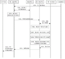
Fig. 5 is a signaling interaction diagram of another method for acquiring a URSP according to an embodiment of the present application. The method can be used for obtaining the URSP scene of the VPLMN from the policy control function network element of the VPLMN when the user equipment is registered in the VPLMN. For example, the user equipment in fig. 5 is UE101 in fig. 1, the RAN equipment is RAN equipment 102 in fig. 1, the first AMF network element and the second AMF network element are AMF network element 103 in fig. 1, the NSSF network element is NSSF network element 104 in fig. 1, the first PCF network element is PCF network element 105 of VPLMN in fig. 1, the second PCF network element is PCF network element 107 of HPLMN in fig. 1, and the UDM network element is UDM network element 106 in fig. 1. Fig. 5 will be described in conjunction with fig. 2 to 4. As shown in fig. 5, the method may include:
s501, the user equipment sends a requested Network Slice Selection Assistance Information (NSSAI) to the RAN equipment, and accordingly, the RAN equipment receives the requested NSSAI from the user equipment. Wherein NSSAI is a set of S-NSSAIs, i.e., one or more S-NSSAIs are included in NSSAI. The user equipment selects a network slice at initial network entry based on the requested NSSAI.
For example, when the user equipment initiates initial registration after moving to the VPLMN, step S501 may be performed.
The requested NSSAI may be an NSSAI configured before the user equipment interacts with the VPLMN.
The user equipment may also send a persistent identifier (SUPI) of the user equipment and the type of radio access network requesting access to the RAN equipment.
S502, the RAN device determines the first AMF network element in the VPLMN according to the requested NSSAI. And the determined first AMF network element is an initial AMF network element.
For example, the RAN device selects the first AMF network element according to the SUPI, the requested NSSAI, and the radio access network type, and if the RAN device cannot select an AMF network element that meets the requirement, determines the default AMF network element as the first AMF network element according to the local policy information.
S503, the RAN device sends the requested NSSAI to the first AMF network element, and accordingly, the first AMF network element receives the requested NSSAI from the RAN device.
For example, the RAN device may also send the SUPI to the first AMF network element.
S504, the first AMF network element obtains the first subscription data from the UDM network element of the HPLMN.
For example, the first AMF network element may obtain the first subscription data from the UDM network element of the HPLMN by sending a request message, or by calling a service. For example, the first AMF network element sends a request message including the SUPI to the UDM network element, or the first AMF network element requests to acquire the first subscription data by calling the numdm _ subscriberdanagement _ Get service, and the UDM network element returns the first subscription data by calling the numdm _ subscriberdanagement _ Get response service.
For example, the first subscription data includes an association of the S-NSSAI and DNN of the subscription. The association of the signed S-NSSAI with the DNN is shown in table 16. In the example of table 16: the subscriptions S-NSSAIs include S-NSSAI1 and S-NSSAI 2, where S-NSSAI1 corresponds to DNN1 and S-NSSAI 2 corresponds to DNN 2 and DNN 3.
TABLE 16
| Subscription S-NSSAIs
|
DNN
|
| S-NSSAI 1
|
DNN 1
|
| S-NSSAI 2
|
DNN 2,DNN 3 |
The method for the ue to acquire the URSP may be further described with reference to fig. 6 if the first AMF network element supports a network slice corresponding to the NSSAI requested by the ue.
If the first AMF network element does not support the network slice corresponding to the NSSAI requested by the user equipment, the first AMF network element performs step S505 after step S504.
S505, the first AMF network element obtains the mapping relation from the NSSF network element of the VPLMN.
For example, the request of the first AMF network element to obtain the mapping relationship from the NSSF network element of the VPLMN may be through a manner of sending a request message, or through a manner of invoking a service. For example, the first AMF network element requests to acquire the mapping relationship by calling a Slice Selection request service, and the UDM network element returns the mapping relationship by calling a Slice Selection response service. The mapping relation comprises a first mapping relation. For example, the first mapping relationship may refer to the description of step S305 in fig. 3, and is not described herein again. In addition, the mapping relationship may further include a second mapping relationship.
For example, the first AMF network element requests the NSSF network element to acquire the mapping relationship by sending the requested NSSAI, the subscribed NSSAI, and the PLMN identity in the SUPI to the NSSF network element of the VPLMN. The NSSF network element knows that the user equipment is a roaming user according to the PLMN identification in the SUPI, and determines a target AMF set and a first allowed NSSAI. Wherein, the target AMF set refers to one or more AMFs meeting the requirements of the user equipment, and the S-NSSAI contained in the first allowed NSSAI is the S-NSSAI of the network slice which can be used by the user equipment in the VPLMN. If different S-NSSAI is adopted by HPLMN and VPLMN, the NSSF network element also generates the mapping relation according to the roaming agreement between VPLMN and HPLMN. The mapping relation is the mapping relation between the S-NSSAI in the HPLMN and the S-NSSAI in the VPLMN.
For example, the first AMF network element is further configured to request the NSSF network element to select an AMF network element that satisfies the NSSAI requested by the user equipment by calling the Slice Selection request service.
S506, the first AMF network element sends redirection information to the second AMF network element, and correspondingly, the second MF network element receives the redirection information from the first AMF network element. And the second AMF network element is one AMF network element selected by the first AMF network element from the target AMF set in the second response message.
For example, the redirection information includes a first allowed NSSAI. Optionally, the redirection message further includes the mapping relationship obtained in step S505.
Optionally, the redirection information further includes the requested NSSAI and the subscribed S-NSSAI.
And S507, the second AMF network element determines the first temporarily rejected S-NSSAI. Wherein the first temporarily rejected S-NSSAI refers to the S-NSSAI of the network slice that is included in the requested NSSAI and belongs to the subscribed S-NSSAI, but is not deployed in the current registration area. That is, the first temporarily rejected S-NSSAI is contained in the contracted S-NSSAI, but not in the first allowed NSSAI.
For example, the relationship of the requested NSSAI, the subscribed S-NSSAIs, the first allowed NSSAI, and the first temporarily rejected S-NSSAI may be as shown in Table 17. In table 17, the user equipment requested NSSAI includes S-NSSAI1, S-NSSAI 2, S-NSSAI 3, and S-NSSAI 4, the user equipment subscribed S-NSSAIs includes S-NSSAI1, S-NSSAI 2, and S-NSSAI 3, the first allowed S-NSSAIs includes S-NSSAI1 and S-NSSAI 2, and the first temporarily rejected NSSAI includes S-NSSAI 3. S-NSSAI 4 is a subscription-impermissible S-NSSAI. For example, the first temporarily rejected S-NSSAI is an S-NSSAI other than the first allowed S-NSSAI in the contracted S-NSSAI. A subscription-impermissible S-NSSAI is an S-NSSAI of the requesting NSSAI other than the subscription S-NSSAI.
TABLE 17
| Requested NSSAI
|
S-NSSAI 1,S-NSSAI 2,S-NSSAI 3,S-NSSAI 4
|
| S-NSSAIs for subscription
|
S-NSSAI 1,S-NSSAI 2,S-NSSAI 3
|
| First allowed NSSAI
|
S-NSSAI 1,S-NSSAI 2
|
| First temporarily rejected S-NSSAI
|
S-NSSAI 3 |
S508, the second AMF network element requests the first PCF network element to generate a second URSP. Wherein, the first PCF network element is a PCF network element selected by the second AMF network element in the VPLMN. For example, the second AMF network element may also request the first PCF network element to generate a second URSP in the VPLMN by invoking the Npcf _ AMPolicyControl _ Get service.
Optionally, in step S508, the second AMF network element may further send the mapping relationship to the first PCF network element, and correspondingly, the first PCF network element receives the mapping relationship from the second AMF network element.
Optionally, the second AMF network element sends the first allowed NSSAI, or the first allowed NSSAI and the first temporarily rejected S-NSSAI, to the first PCF network element.
Optionally, the second AMF network element may further send the first subscription data to the first PCF network element.
S509, the first PCF network element obtains the first URSP from the second PCF network element.
For example, the request of the first PCF network element to obtain the first URSP from the second PCF network element may be by sending a request message, or by invoking a service. For example, a first PCF network element requests to obtain a first URSP by invoking the Npcf _ ampolicocontrol _ get (supi) service, and a second PCF network element returns the first URSP by invoking the Npcf _ ampolicocontrol _ Response service. Wherein the first URSP includes a first rule. The first rule is for indicating an association between a first S-NSSAI, a first application, and a first DNN, the first DNN for identifying a first DN, the first DN allowing LBO and supporting the first application and the second application.
Optionally, the second PCF network element sends the first subscription data to the first PCF network element. Correspondingly, the first PCF network element receives the first subscription data from the second PCF network element. It should be noted that the first PCF network element may send the first subscription data and the first URSP through the same message, or may send them through different messages.
Thus, the first PCF may be able to obtain the subscription data from the second PCF network element through the optional steps in S509 above. Alternatively, the first PCF may also be able to obtain the subscription data from the second AMF through step S508. It should be noted that the first PCF may obtain the subscription data in any one of the two manners, or the first PCF may also obtain the subscription data in other manners, which is not limited in this embodiment.
S510, the first PCF network element determines that the first DN allows LBO.
S511, the first PCF network element determines that the first DN supports the second application.
S512, the first PCF network element adds a fourth rule to the first URSP, wherein the fourth rule includes an association between the first S-NSSAI, the second application, and the first DNN.
S513, the first PCF network element determines the second URSP according to the first URSP added with the fourth rule.
S515, the first PCF network element sends the second URSP to the second AMF network element, and correspondingly, the second AMF network element receives the second URSP from the first PCF network element. Wherein the second URSP comprises a second rule for indicating an association between the second S-NSSAI, the first application and the first DNN, and a third rule for indicating an association between the second S-NSSAI, the second application and the first DNN. Wherein the second S-NSSAI is the same as or corresponds to the first S-NSSAI.
For example, the first PCF network element may send the second URSP to the second AMF network element by sending a message, or by invoking a service. For example, the first PCF network element sends the second URSP by calling the Npcf _ ampolicocontrol _ Response service.
Optionally, the first PCF network element may further send an identity of the VPLMN to the second AMF network element, where the identity of the VPLMN is associated with the second URSP.
Optionally, the first PCF network element may further send the identifier of the first URSP and the HPLMN to the second AMF network element, where the identifier of the HPLMN is associated with the first URSP.
Optionally, before step S515, the first PCF network element may perform step S514.
S514, the second PCF network element sends the indication information to the first PCF network element. Accordingly, the first PCF network element receives the indication information from the second PCF network element. The indication is used to trigger the sending of the identity of the first URSP and the HPLMN to the user equipment.
The above steps S510 to S512 can refer to the descriptions of S203 to S205 in fig. 2; the above step S513 may refer to the description of S205 in fig. 2 or S306 in fig. 3; the above step S514 can refer to the description of S406 in fig. 4. So steps S510 to S514 will not be described herein.
And S515, the first PCF network element sends the second URSP to the second AMF network element.
S516, the second AMF network element sends the first allowed NSSAI and the second URSP to the user equipment. Accordingly, the user equipment receives the first allowed NSSAI and the second URSP from the second AMF network element. For example, the first allowed NSSAI and the second URSP may be transmitted via a Registration accept (Registration _ accept) message.
S517, the user equipment saves the first allowed NSSAI and the second URSP.
For example, after the user equipment stores the first allowed NSSAI and the second URSP, when the APP is started in the VPLMN, the session establishment procedure is initiated to the network side through the S-NSSAI carrying the network slice corresponding to the APP in the second URSP.
Therefore, when the first AMF network element selected by the RAN equipment does not support the network slice corresponding to the NSSAI requested by the user equipment in the process of registering the user equipment to the VPLMN, the user equipment may obtain the second URSP of the VPLMN according to the method of the embodiment of the present invention. The second URSP also includes APPs that are not present in the first URSP of the HPLMN but can be used in the LBO scenario of the VPLMN. The user equipment can use more APPs in the LBO scene of the VPLMN according to the second URSP obtained in the scheme, so that the user experience is improved.
In addition, in the scheme, the user equipment can obtain the second URSP in the registration process, and compared with a method that the user equipment generates the second URSP according to the received roaming agreement among the first URSP of the HPLMN, the VPLMN and the HPLMN, the user equipment does not need to sense the roaming agreement on the network side, so that the network security is enhanced.
Fig. 6 is a signaling interaction diagram of another method for acquiring a URSP according to an embodiment of the present application. The applicable scenario of the method is the same as the embodiment shown in fig. 5. The difference between the embodiment shown in fig. 6 and fig. 5 is that: in the embodiment of fig. 5, the first AMF network element does not support the network slice corresponding to the NSSAI requested by the user equipment; in the embodiment of fig. 6, the first AMF network element supports the network slice corresponding to the NSSAI requested by the user equipment. Fig. 6 will be described in conjunction with fig. 5.
Step S601 to step S604 can refer to the descriptions of step S501 to step S504 in fig. 5, which are not repeated herein.
S605, the first AMF network element determines the mapping relation.
For example, when the HPLMN and the VPLMN employ different S-NSSAIs, the first AMF network element generates the mapping relationship according to a roaming agreement between the VPLMN and the HPLMN. The mapping relation is the mapping relation between the S-NSSAI in the HPLMN and the S-NSSAI in the VPLMN.
S606, the first AMF network element determines the first allowed NSSAI. Wherein the S-NSSAI included in the first allowed NSSAI is the S-NSSAI of the network slice that the user equipment can use in the VPLMN.
Since the first AMF network element supports the network slice corresponding to the NSSAI requested by the user equipment, the first AMF network element may perform similar operations as the second AMF network element in fig. 5, starting from step S607. For example,
s607, the first AMF network element determines the first temporarily rejected S-NSSAI.
The first AMF network element determines the first temporarily rejected S-NSSAI in step S607, refer to step S507 in fig. 5, where the second AMF network element determines the description of the first temporarily rejected S-NSSAI, and details are not described here again.
S608, the first AMF network element sends the mapping relationship to the first PCF network element, and correspondingly, the first PCF network element receives the mapping relationship from the first AMF network element.
The step S608 may refer to step S508 in fig. 5, where the first AMF network element sends the mapping relationship to the first PCF network element, and details of the step S may be omitted here.
Step S609 to step S614 can refer to the descriptions of S509 to S514 in fig. 5, which are not repeated herein.
S615, the first PCF network element sends the second URSP to the first AMF network element, and correspondingly, the first AMF network element receives the second URSP from the first PCF network element.
S616, the first AMF network element sends the first allowed NSSAI and the second URSP to the user equipment. Accordingly, the user equipment receives the first allowed NSSAI and the second URSP from the first AMF network element.
In the above step S616, the first AMF network element sends the first allowed NSSAI and the second URSP to the user equipment, refer to step S516 in fig. 5, where the second AMF network element sends descriptions of the first allowed NSSAI and the second URSP to the user equipment, and details are not repeated here.
Step S617 may refer to the description of S517 in fig. 5, and is not described herein again.
Therefore, when the first AMF network element selected by the RAN equipment supports the network slice corresponding to the NSSAI requested by the user equipment during the registration process of the user equipment to the VPLMN, the user equipment may obtain the second URSP of the VPLMN according to the method of the embodiment of the present invention. The second URSP also includes APPs that are not present in the first URSP of the HPLMN but can be used in the LBO scenario of the VPLMN. The user equipment can use more APPs in the LBO scene of the VPLMN according to the second URSP obtained in the scheme, so that the user experience is improved. In addition, in the scheme, the user equipment can obtain the second URSP in the registration process, and compared with a method that the user equipment generates the second URSP according to the received roaming agreement among the first URSP of the HPLMN, the VPLMN and the HPLMN, the user equipment does not need to sense the roaming agreement on the network side, so that the network security is enhanced.
Fig. 7 is a flowchart of another method for acquiring a URSP according to an embodiment of the present application. The method can be used for the user equipment to obtain the URSP scene of the VPLMN when the subscription information of the user equipment is changed. Fig. 7 will be described in conjunction with fig. 5.
S701, the UDM network element of the HPLMN sends the second subscription data to the second AMF network element, and correspondingly, the second AMF network element receives the second subscription data from the UDM network element. And the second subscription data is the subscription data after the first subscription data is updated.
For example, the UDM network element of the HPLMN may send the second subscription data to the second AMF network element by sending a message, or by calling a service. For example, the UDM network element sends the second subscription data by invoking the numdm _ SubscriberData _ Get response service.
For example, the second AMF network element subscribes to the subscription data, and after the subscription data is updated, the UDM network element sends the second subscription data after the first subscription data is updated to the second AMF network element. Assume that the first subscription data is shown in table 16 and the updated second subscription data is shown in table 18. In the example of table 18: the second subscription S-NSSAIs comprise S-NSSAI1, S-NSSAI 2 and S-NSSAI 3, wherein S-NSSAI1 corresponds to DNN1, S-NSSAI 2 corresponds to DNN 2 and DNN 3, and S-NSSAI 3 corresponds to DNN 4. The second subscription data adds the association of S-NSSAI 3 with DNN 4 relative to the first subscription data in table 16.
Watch 18
| Subscription S-NSSAIs
|
DNN
|
| S-NSSAI 1
|
DNN 1
|
| S-NSSAI 2
|
DNN 2,DNN 3
|
| S-NSSAI 3
|
DNN 4 |
S702, the second AMF network element obtains the second allowed NSSAI from the NSSF network element of the VPLMN. Wherein the second allowed NSSAI is an updated allowed NSSAI.
For example, the steps S703 to S713 may refer to the descriptions of the steps S707 to S717 in fig. 5, and are not described herein again. In steps S703 to S713, the second temporarily rejected S-NSSAI is the updated temporarily rejected S-NSSAI, the third URSP is the updated URSP of the first URSP, and the fourth URSP is the updated URSP of the second URSP.
Therefore, according to the method in the embodiment of the present invention, when the subscription information of the user equipment changes, the first policy control function network element may generate a new second URSP, that is, a fourth URSP, through the updated third URSP of the first URSP and the updated first mapping relationship, and send the new second URSP, that is, the fourth URSP, to the user equipment. The user equipment can obtain the fourth URSP after the subscription information is updated, and obtain the updated APP information which can be used locally according to the fourth URSP, so that the user experience is improved.
In the above description, the rule (for example, any one of the first to sixth rules) for indicating the association among the network slice identification information, the application and the data network identification information may be implemented by a correspondence among a piece of network slice identification information, an application and a data network identification information, or may be implemented by a combination of correspondences of any two of the three (for example, a correspondence between a piece of network slice identification information and an application, and a relationship between a piece of application and a data network name), and the present application is not limited thereto.
In the embodiments provided in the present application, the schemes of the communication method provided in the embodiments of the present application are introduced from the perspective of each network element itself and from the perspective of interaction between each network element. It is to be understood that each network element, such as the first PCF network element, the second PCF network element, and the AMF network element described above, includes corresponding hardware structures and/or software modules for performing each function in order to implement the above functions. Those of skill in the art would readily appreciate that the various illustrative elements and algorithm steps described in connection with the embodiments disclosed herein may be implemented as hardware or combinations of hardware and computer software. Whether a function is performed as hardware or computer software drives hardware depends upon the particular application and design constraints imposed on the solution. Skilled artisans may implement the described functionality in varying ways for each particular application, but such implementation decisions should not be interpreted as causing a departure from the scope of the present application.
For example, when the network element implements the corresponding functions through software modules. The means for acquiring the user policy may include a receiving module 801 and a sending module 803, as shown in fig. 8A. Optionally, the apparatus for acquiring a user policy further includes a processing module 802.
In one embodiment, the means for obtaining the user policy may be configured to perform the operations of the first policy control function network element (e.g., the first PCF network element) in fig. 2 to 7. For example:
the receiving module 801 is configured to receive a first user policy of the HPLMN from a policy control function network element for the HPLMN. The first user policy includes a first rule, where the first rule is used to indicate an association among first network slice identification information, a first application, and first data network identification information, where the first data network identification information is used to identify a first data network, and the first data network allows LBO and supports the first application and a second application. A sending module 803, configured to send the second user policy of the VPLMN to the user equipment. The second user policy includes a second rule and a third rule, the second rule is used for indicating association among the second network slice identification information, the first application and the first data network identification information, and the third rule is used for indicating association among the second network slice identification information, the second application and the first data network identification information.
Therefore, by the apparatus for acquiring the user policy in the embodiment of the present invention, the second URSP of the VPLMN, which is acquired by the user equipment, includes information of APPs that do not exist in the first URSP of the HPLMN but can be used in an LBO scenario of the VPLMN, for example, information of the second application. The user equipment can use more APP services in the LBO scene of the VPLMN according to the obtained second URSP, so that the user experience is improved.
Optionally, the sending module 803 is further configured to send, to the user equipment, an identity of the VPLMN, where the identity of the VPLMN is associated with the second user policy.
Optionally, the sending module 803 is further configured to send the first user policy and an identifier of the HPLMN to the user equipment, where the identifier of the HPLMN is associated with the first user policy.
Optionally, before the sending module 803 sends the first user policy and the identity of the HPLMN to the user equipment, the receiving module 801 is further configured to receive indication information from the policy control function network element, where the indication information is used to trigger sending of the first user policy and the identity of the HPLMN to the user equipment.
Optionally, the processing module 802 for obtaining the user policy is configured to add the fourth rule to the first user policy. The fourth rule comprises the association among the first network slice identification information, the second application and the first data network identification information, and the processing module is further used for determining a second user policy according to the first user policy added with the fourth rule.
Optionally, the processing module 802 is further configured to determine that the first data network allows LBO and determine that the first data network supports the second application.
Optionally, when the second network slice identification information is the same as the first network slice identification information, the second user policy is the first user policy after the fourth rule is added.
Optionally, when the second network slice identification information corresponds to the first network slice identification information, the receiving module 801 is configured to receive, from the access and mobility management function network element of the VPLMN, a first mapping relationship between the first network slice identification information and the second network slice identification information; the processing module 802 is configured to determine a second user policy according to the first mapping relationship and the first user policy after adding the fourth rule.
Optionally, the processing module 802 is configured to map, according to the first mapping relationship, the first network slice identification information in the first user policy added with the fourth rule into second network slice identification information, so as to generate a second user policy.
Optionally, the receiving module 801 is further configured to receive, from the access and mobility management function network element of the VPLMN, a first mapping relationship between the first network slice identification information and the second network slice identification information, where the first mapping relationship is used for generating the second user policy.
Optionally, the first user policy further includes a fifth rule, where the fifth rule is used to indicate an association between third network slice identification information, the third application, and second data network identification information, where the second data network identification information is used to identify a second data network, and the second data network prohibits LBO; the second user policy further comprises a sixth rule for indicating an association between fourth network slice identification information, the third application and the second data network identification information, wherein the fourth network slice identification information is the same as the third network slice identification information.
Optionally, the first user policy further includes a fifth rule, where the fifth rule is used to indicate an association between third network slice identification information, the third application, and second data network identification information, where the second data network identification information is used to identify a second data network, and the second data network prohibits LBO; the second user policy further includes a sixth rule for indicating an association between fourth network slice identification information, the third application, and the second data network identification information, wherein the fourth network slice identification information corresponds to the third network slice identification information.
Optionally, the receiving module 801 is further configured to receive, from the access and mobility management function network element of the VPLMN, a second mapping relationship between the third network slice identification information and the fourth network slice identification information; the processing module 802 is further configured to determine fourth network slice identification information according to the third network slice identification information and the second mapping relationship.
In addition, the receiving module 801, the processing module 802, and the sending module 803 in the apparatus for obtaining a user policy may also implement other operations or functions of the first policy control function network element in the above method, which is not described herein again.
In another embodiment, the apparatus for obtaining a user policy shown in fig. 8A may be further configured to perform the operation of the second policy control function network element (e.g., the second PCF network element) in fig. 4. For example:
the sending module 803 is configured to send the user policy of the HPLMN to the first policy control function network element of the VPLMN, and is further configured to send the indication information to the first policy control function network element. Wherein the indication information is used to trigger the sending module 803 to send the user policy of the HPLMN and the identity of the HPLMN to the user equipment. The identity of the HPLMN is associated with a user policy of the HPLMN.
Therefore, the first policy control function network element of the VPLMN can receive the user policy of the HPLMN, and generate the user policy of the VPLMN according to the user policy of the HPLMN. The user policy of the VPLMN includes information of APPs which are not present in the user policy of the HPLMN but can be used in an LBO scenario of the VPLMN. The user equipment can use more APP services in the LBO scene of the VPLMN according to the obtained second user strategy, so that the user experience is improved. In addition, after receiving the trigger of the indication information, the policy control function network element of the VPLMN sends the user policy and the HPLMN identifier to the user equipment, so that the user equipment is prevented from repeatedly acquiring the user policy of the HPLMN, the interaction between the user equipment and the network can be reduced, and the time delay is reduced.
In addition, the receiving module 801, the processing module 802, and the sending module 803 in the apparatus for obtaining a user policy may also implement other operations or functions of the second policy control function network element in the method, which is not described herein again.
In yet another embodiment, the apparatus for acquiring a user policy shown in fig. 8A may be further configured to perform the operations of the access and mobility management function network element (e.g., AMF network element) in fig. 3. For example:
the sending module 803 is configured to send the mapping relationship between the first network slice identification information and the second network slice identification information to the first policy control function network element. The first network slice identification information is network slice identification information in an HPLMN supported by a data network, the second network slice identification information is network slice identification information in a VPLMN supported by the data network, and the mapping relation is used for determining the second network slice identification information.
In the prior art, the user equipment needs to obtain the mapping relationship between the first network slice identification information and the second network slice identification information from the access and mobility management functional network element of the VPLMN, so as to generate the second user policy. According to the prior art, the user equipment can sense the roaming agreement between the VPLMN and the HPLMN through the mapping relation. According to the method provided by the application, the user equipment acquires the second user policy from the network side, so that a roaming protocol between the VPLMN and the HPLMN does not need to be sensed, and the security performance of the network is improved.
In addition, the receiving module 801, the processing module 802, and the sending module 803 in acquiring the user policy may also implement other operations or functions of the access and mobility management function network element in the above method, which is not described herein again.
Fig. 8B shows another possible structure diagram of the apparatus for acquiring a user policy involved in the above embodiment. The means for obtaining the user policy comprises the transceiver 804 and the processor 805, as shown in fig. 8B. For example, the processor 805 may be a general purpose microprocessor, a data processing circuit, an Application Specific Integrated Circuit (ASIC), or a field-programmable gate array (FPGA) circuit. The means for obtaining the user policy may further include a memory 806, for example, a Random Access Memory (RAM). The memory is for coupling with the processor 805, which holds the necessary computer programs 8061 for the means for obtaining user policies.
Furthermore, the method for acquiring a user policy according to the above embodiment further provides a carrier 807, in which a computer program 8071 of the apparatus for acquiring a user policy is stored, and the computer program 8071 may be loaded into the processor 805. The carrier may be an optical signal, an electrical signal, an electromagnetic signal, or a computer readable storage medium (e.g., a hard disk).
The computer program 8061 or 8071, when executed on a computer (e.g., the processor 805), can cause the computer to perform the methods described above.
For example, in one embodiment, the processor 805 is configured to control other operations or functions of the functional network element. The transceiver 804 is configured to implement the means for obtaining the user policy in communication with a second policy control function network element/access and mobility management function network element/user equipment.
In another embodiment, the processor 805 is configured to control other operations or functions of the functional network element. The transceiver 804 is used for implementing communication between the device for obtaining the user policy and a policy control function network element of the VPLMN.
In another embodiment, the processor 805 is configured to perform the corresponding functions of the first NF network element in the above method by the communication apparatus. The transceiver 804 is configured to implement communication between the means for obtaining the user policy and the first NRF network element.
The controller/processor for implementing the radio access network devices described above may be a Central Processing Unit (CPU), general purpose processor, Digital Signal Processor (DSP), Application Specific Integrated Circuit (ASIC), Field Programmable Gate Array (FPGA) or other programmable logic device, transistor logic device, hardware component, or any combination thereof. Which may implement or perform the various illustrative logical blocks, modules, and circuits described in connection with the disclosure. The processor may also be a combination of computing functions, e.g., comprising one or more microprocessors, DSPs, and microprocessors, among others.
The steps of a method or algorithm described in connection with the disclosure herein may be embodied in hardware or in software instructions executed by a processor. The software instructions may consist of corresponding software modules that may be stored in RAM memory, flash memory, ROM memory, EPROM memory, EEPROM memory, registers, a hard disk, a removable disk, a CD-ROM, or any other form of storage medium known in the art. An exemplary storage medium is coupled to the processor such the processor can read information from, and write information to, the storage medium. Of course, the storage medium may also be integral to the processor. The processor and the storage medium may reside in an ASIC. Additionally, the ASIC may reside in a radio access network device. Of course, the processor and the storage medium may reside as discrete components in a radio access network device.
In the above embodiments, the implementation may be wholly or partially realized by software, hardware, firmware, or any combination thereof. When implemented in software, may be implemented in whole or in part in the form of a computer program product. The computer program product includes one or more computer instructions. When loaded and executed on a computer, cause the processes or functions described in accordance with the embodiments of the invention to occur, in whole or in part. The computer may be a general purpose computer, a special purpose computer, a network of computers, or other programmable device. The computer instructions may be stored in a computer readable storage medium or transmitted from one computer readable storage medium to another, for example, from one website site, computer, server, or data center to another website site, computer, server, or data center via wired (e.g., coaxial cable, fiber optic, Digital Subscriber Line (DSL)) or wireless (e.g., infrared, wireless, microwave, etc.). The computer-readable storage medium can be any available medium that can be accessed by a computer or a data storage device, such as a server, a data center, etc., that incorporates one or more of the available media. The usable medium may be a magnetic medium (e.g., floppy Disk, hard Disk, magnetic tape), an optical medium (e.g., DVD), or a semiconductor medium (e.g., Solid State Disk (SSD)), among others.
The above-mentioned embodiments, objects, technical solutions and advantages of the present invention are further described in detail, it should be understood that the above-mentioned embodiments are only exemplary embodiments of the present invention, and are not intended to limit the scope of the present invention, and any modifications, equivalent substitutions, improvements and the like made on the basis of the technical solutions of the present invention should be included in the scope of the present invention.