Disclosure of Invention
Aiming at the defects in the prior art, the invention provides an aerosol generating device based on hot air flow heating.
The invention relates to an aerosol generating device based on hot air flow heating, which comprises: a housing, a receiving portion and a heat generating component, the receiving portion and the heat generating component being disposed in the housing, wherein
The accommodating part is provided with an opening, a side wall and a bottom surface, a cavity for accommodating the aerosol forming substrate is limited by the side wall, the aerosol forming substrate is received by the opening, a gap is formed between the side wall and the shell and can be used for airflow to pass through, a first airflow inlet is arranged at the position, close to the bottom surface, of the side wall,
the heating component is arranged below the containing part and comprises a cylinder body and a heating circuit arranged on the inner wall of the cylinder body, a gap is formed between the outer wall of the cylinder body and the shell and can be used for air flow to pass through, one end of the cylinder body, which is far away from the containing part, is provided with a second air flow inlet, one end of the cylinder body, which is close to the containing part, is provided with an air flow outlet, an annular partition part is also arranged between the outer wall surface of the cylinder body and the shell, so that the second air flow inlet is positioned below the annular partition part, and the air flow outlet is positioned above the annular partition part,
and a third airflow inlet is formed in the position, corresponding to the second airflow inlet, of the shell.
Preferably, a first air flow channel is formed inside the heat generating component, a second air flow channel is formed by a gap between the outer shell and the outer wall of the barrel part of the heat generating component and the side wall of the accommodating part, and a third air flow channel is formed inside the aerosol-forming substrate.
Preferably, the heating circuit is composed of a resistance wire, and the resistance wire is spirally arranged on the inner wall of the cylinder.
Preferably, the heating circuit is formed by printing a conductive paste pattern on an inner wall of the cylinder.
Preferably, the heating circuit is formed by attaching a support carrying a conductive paste pattern to an inner wall of the cylinder.
Preferably, the bottom surface of the accommodating part is provided with an annular convex part which takes the center of the circle of the bottom surface as the center.
Preferably, the annular projection is further provided with a plurality of grooves in the radial direction.
Preferably, the casing has a double-layer structure including an outer wall layer and an inner wall layer, an annular slit is formed between the outer wall layer and the inner wall layer, the annular slit has a fourth airflow inlet at one end close to the mouth of the user, and the other end of the annular slit is communicated with the third airflow inlet.
Preferably, a fourth air flow channel is formed in the annular slit.
The invention has the beneficial effects that: the aerosol generating device adopts hot air flow to heat the cigarette, so that the tobacco section of the heated cigarette is sufficiently heated, no special requirement is required on the arrangement mode of the tobacco base materials, the cigarette production difficulty is reduced, and paper burnt flavor cannot be generated because the outer surface of the heated cigarette is not directly heated, so that the smoking experience can be improved.
Detailed Description
The embodiments of the present invention will be described below with reference to the drawings attached to the specification. It should be noted that the embodiments mentioned in the present description are not exhaustive and do not represent the only embodiments of the present invention. The following examples are given for the purpose of clearly illustrating the inventive contents of the present patent application and are not intended to limit the embodiments thereof. It will be apparent to those skilled in the art that various changes and modifications can be made in the embodiment without departing from the spirit and scope of the invention, and it is intended to cover all such changes and modifications as fall within the true spirit and scope of the invention.
An "aerosol-generating device" in the present invention relates to a device which interacts with an aerosol-forming substrate to produce an aerosol (smoke or aerosol). The aerosol-forming substrate may be part of an aerosol generating article (e.g. a smoking article). The aerosol-generating device may comprise one or more components for supplying energy from an energy source to the aerosol-forming substrate to generate an aerosol, which is inhalable directly into the user's lungs through the user's mouth.
An "aerosol-forming substrate" in the present invention is a substrate capable of releasing volatile compounds that can form an aerosol. Such volatile compounds may be released by heating the aerosol-forming substrate. For example, the "aerosol-forming substrate" may be a wick substrate.
As shown in fig. 1 to 4, an aerosol generating device based on hot air flow heating according to the present invention includes: the heating device comprises an upper shell 1, a lower shell 2, a containing part 3 and a heating component 4, wherein the containing part 3 and the heating component 4 are arranged in the upper shell 1. The upper housing 1 is generally cylindrical in shape with one end being the portion adjacent the mouth of the user. This portion is referred to herein as the "proximal end" or "proximal end" of the upper housing, while the portion opposite the "proximal end" is referred to as the "distal end" or "distal end" of the upper housing. The distal end of the upper housing 1 is detachably connected to the lower housing 2. The upper case 1 and the lower case 2 together constitute a case (outer case) of the aerosol generating apparatus.
The housing 3 has an opening 31, a side wall 32, and a bottom surface 33. A cavity for receiving an aerosol-forming substrate 5 is defined by the side wall 32, the aerosol-forming substrate 5 being received by the opening 31 from the proximal end of the upper housing 1, a void 6 (in particular a portion of the void 6) being formed between the side wall 32 and the upper housing 1 for the airflow to pass through, and a first airflow inlet 34 being provided in the side wall 32 adjacent the bottom surface 33. The first air flow inlet 34 may be a plurality of openings or holes along the sidewall. Other gas flow inlets or outlets, mentioned below, may employ this configuration.
The heating element 4 is disposed below the accommodating portion 3, and specifically, the heating element 4 is fixedly connected to the accommodating portion 3. The heating element 4 includes a cylinder 41 and a heating circuit 42 disposed on an inner wall of the cylinder 41. Preferably, the cylinder 41 of the heating element 4 is a ceramic cylinder to perform a heat insulation function and reduce the loss of internal heat. The heating circuit 42 is connected to a controller (shown in fig. 5) to control the heating power, heating time, etc. of the heating circuit.
A gap 6 (specifically, another part of the gap 6) formed between the outer wall of the cylinder and the upper shell can allow airflow to pass through. That is, the gap 6 is an annular space extending from the outside of the accommodating portion 2 to the outside of the heat generating component 4, that is, between the outside of both the accommodating portion 2 and the heat generating component 4 and the upper case 1. The end of the cylinder 41 far away from the accommodating part 3 is provided with a second airflow inlet 43, the end of the cylinder 41 near the accommodating part 3 is provided with an airflow outlet 44, and an annular partition part 7 is further arranged between the outer wall surface of the cylinder and the shell, so that the second airflow inlet 43 is positioned below the annular partition part 7, and the airflow outlet 44 is positioned above the annular partition part 7. That is, the annular partition 7 partitions the gap 6 into upper and lower portions, and blocks the flow of air. The annular partition 7 may be a partition plate extending from the casing (upper casing) 1, that is, integrally formed with the upper casing 1, or may be a separate partition member, which is preferably capable of blocking the flow of air between the upper and lower portions of the gap 6.
The upper case 1 further has a third air inlet 11 at a position corresponding to the second air inlet 43.
With the above structure of the present invention, as shown in fig. 1, when a user sucks the aerosol generating device, the external air flows into the gap 6 from the third air flow inlet 11 and flows into the heat generating component 4 from the second air flow inlet 43, a first air flow channel is formed inside the heat generating component 4, the air is heated inside the heat generating component 4 to form a hot air flow, and the hot air flow flows out from the air flow outlet 44. The hot air flow then enters the gap 6, i.e. the second air flow channel, in particular the part above the annular partition 7 of the gap 6, after passing through the second air flow channel, it enters the aerosol-forming substrate 5 through the first air flow inlet 44, forming a third air flow channel inside said aerosol-forming substrate 5, so that the hot air flow heats the aerosol-forming substrate 5 to form smoke that finally enters the mouth of the user.
The bottom surface structure of the accommodating portion will be described below with specific reference to fig. 2. As shown in fig. 2, the bottom surface 33 of the housing portion 3 has an annular projection 35 centered on the center of the bottom surface. In a preferred embodiment, the annular protrusion 35 is formed as an annular step centered on the center of the bottom surface. The height of the annular step can be 1mm to 3 mm. The annular step is also formed with a plurality of grooves 36 in the radial direction to facilitate the flow of the second air flow path into the third air flow path. Preferably, there may be two grooves or three grooves. In other embodiments, the protrusions 35 may also be provided as a plurality of bumps or a plurality of strip-like protrusions or the like, so as to be able to support the end face of the aerosol-forming substrate 5, preferably such that a certain space is formed between the end face of the aerosol-forming substrate 4 and the bottom face 33 of the receptacle 3. At the same time, this space may also function to collect the smoke residue or debris that falls off the end face of the aerosol-forming substrate 5, which may be conveniently cleaned after the user has finished removing the aerosol-forming substrate 5 after smoking.
The structure of the heating circuit of the heat generating component is explained below with reference to fig. 3. As shown in fig. 3, in a preferred embodiment, the heating circuit 42 can be a resistance wire, which is in a spiral structure and is disposed on the inner wall of the cylinder 41. In another embodiment, the heating circuit 42 may be formed by printing a conductive paste pattern on the inner wall of the cylinder. In another embodiment, the heating circuit 42 may be formed by attaching a carrier carrying a conductive paste pattern to the inner wall of the cylinder.
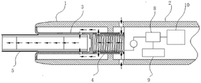
Fig. 4 is a schematic diagram of the overall structure of an aerosol generating device based on hot air flow heating according to an embodiment of the invention. Elements that are not relevant for an understanding of the present invention have been omitted here to simplify fig. 4. As shown in fig. 4, the aerosol generating device includes the upper case 1, the lower case 2, the accommodating portion 3, the heat generating component 4, the controller 8, the user interface 9, and the power supply 10. The user interface 9 may be, for example, a button member. Specifically, the accommodating portion 3, the heat generating component 4 are provided in the upper case 1, and the controller 8, the user interface 9, and the power supply 10 are provided in the lower case 2. The aerosol-forming substrate 5 is accommodated in the accommodating portion 3 of the upper case 1, and the aerosol-forming substrate 5 is heated by the hot air flow heated by the heater element 4. The aerosol-forming substrate 5 releases a range of volatile compounds at different temperatures, thereby generating an aerosol.
The power source 10 in the lower case 2 is, for example, a rechargeable lithium ion battery. The controller 8 is connected to the heat generating unit 4, the button member 9, and the power supply 10. The controller 8 controls the power supplied to the heat-generating component 4 to regulate the heat-generating temperature, typically heating the aerosol-forming substrate to a temperature between 350 and 380 degrees celsius. Preferably, a heat insulation member is further provided between the upper casing 1 and the lower casing 2 to insulate the heat of the heat generating component 4 in the upper casing 1, and to ensure the safety of components such as a power supply in the lower casing 2. The aerosol generating device adopts hot air flow for heating, so that the tobacco section of the heated cigarette is sufficiently heated, no special requirement is required for the arrangement mode of the tobacco base materials, the cigarette production difficulty is reduced, and paper burnt flavor cannot be generated because the outer surface of the heated cigarette is not directly heated, so that the smoking experience can be improved. In addition, the heating mode of the aerosol generating device of the invention can reduce the falling of the smoke residue or fragments because no heating needle or heating sheet penetrates into the tobacco substrate, and even if a small amount of smoke residue or fragments exist, the smoke residue or fragments cannot enter into the heating component to cause the failure of the heating component, thereby prolonging the service life of the aerosol generating device.
Figure 5 is a cross-sectional view of an aerosol generating device heated by a stream of heated air according to another embodiment of the present invention. As shown in fig. 5, the present embodiment is different from the embodiment shown in fig. 1 in that the case is changed from the single-layer structure shown in fig. 1 to the double-layer structure. Specifically, the upper shell 1' has a double-layer structure including an outer wall layer 13 and an inner wall layer 14, an annular slit 15 is formed between the outer wall layer 13 and the inner wall layer 14, the annular slit 15 has a fourth airflow inlet 16 at one end near the mouth of the user, and the other end 17 of the annular slit 15 is communicated with the third airflow inlet 11. That is, the annular slit 15 forms a fourth airflow channel, and one airflow channel is added on the basis of the original three airflow channels.
With the structure shown in fig. 5, when a user sucks the aerosol generating device, the external air flow firstly enters the annular slit 15, i.e. the fourth air flow channel, from the fourth air flow inlet 16, the air flow reaches the bottom of the annular slit 15, i.e. the other end 17, then enters the gap 6 from the third air flow inlet 11, and flows into the heat generating component 4 from the second air flow inlet 43, the first air flow channel is formed inside the heat generating component 4, the air is heated inside the heat generating component 4 to form a hot air flow, and the hot air flow flows out from the air flow outlet 44. The hot air flow then enters the gap 6, i.e. the second air flow channel, in particular the part above the annular partition 7 of the gap 6, after passing through the second air flow channel, it enters the aerosol-forming substrate 5 through the first air flow inlet 34, forming a third air flow channel inside said aerosol-forming substrate 5, so that the hot air flow heats the aerosol-forming substrate 5 to form smoke that finally enters the mouth of the user. With the structure of this embodiment, on the basis of obtaining the aforementioned beneficial effects of the hot air stream heating the aerosol-forming substrate, the temperature of the outer wall of the housing on the sol-generating device can also be effectively reduced, thereby giving the user a comfortable gripping experience during use of the aerosol-generating device.
It will be apparent to those skilled in the art that the above embodiments are merely illustrative of the present invention and are not to be construed as limiting the present invention, and that changes and modifications to the above described embodiments may be made within the spirit and scope of the present invention as defined in the appended claims.