CN114073044A - Distortion cancellation - Google Patents
Distortion cancellation Download PDFInfo
- Publication number
- CN114073044A CN114073044A CN202080046767.1A CN202080046767A CN114073044A CN 114073044 A CN114073044 A CN 114073044A CN 202080046767 A CN202080046767 A CN 202080046767A CN 114073044 A CN114073044 A CN 114073044A
- Authority
- CN
- China
- Prior art keywords
- signal
- packet
- training
- digital
- linear
- Prior art date
- Legal status (The legal status is an assumption and is not a legal conclusion. Google has not performed a legal analysis and makes no representation as to the accuracy of the status listed.)
- Granted
Links
Images


Classifications
-
- H—ELECTRICITY
- H04—ELECTRIC COMMUNICATION TECHNIQUE
- H04B—TRANSMISSION
- H04B1/00—Details of transmission systems, not covered by a single one of groups H04B3/00 - H04B13/00; Details of transmission systems not characterised by the medium used for transmission
- H04B1/06—Receivers
- H04B1/10—Means associated with receiver for limiting or suppressing noise or interference
- H04B1/1027—Means associated with receiver for limiting or suppressing noise or interference assessing signal quality or detecting noise/interference for the received signal
-
- H—ELECTRICITY
- H04—ELECTRIC COMMUNICATION TECHNIQUE
- H04L—TRANSMISSION OF DIGITAL INFORMATION, e.g. TELEGRAPHIC COMMUNICATION
- H04L25/00—Baseband systems
- H04L25/02—Details ; arrangements for supplying electrical power along data transmission lines
- H04L25/03—Shaping networks in transmitter or receiver, e.g. adaptive shaping networks
- H04L25/03006—Arrangements for removing intersymbol interference
- H04L25/03178—Arrangements involving sequence estimation techniques
- H04L25/03248—Arrangements for operating in conjunction with other apparatus
- H04L25/0328—Arrangements for operating in conjunction with other apparatus with interference cancellation circuitry
-
- H—ELECTRICITY
- H04—ELECTRIC COMMUNICATION TECHNIQUE
- H04L—TRANSMISSION OF DIGITAL INFORMATION, e.g. TELEGRAPHIC COMMUNICATION
- H04L25/00—Baseband systems
- H04L25/02—Details ; arrangements for supplying electrical power along data transmission lines
- H04L25/03—Shaping networks in transmitter or receiver, e.g. adaptive shaping networks
- H04L25/03006—Arrangements for removing intersymbol interference
-
- H—ELECTRICITY
- H04—ELECTRIC COMMUNICATION TECHNIQUE
- H04B—TRANSMISSION
- H04B1/00—Details of transmission systems, not covered by a single one of groups H04B3/00 - H04B13/00; Details of transmission systems not characterised by the medium used for transmission
- H04B1/02—Transmitters
- H04B1/04—Circuits
- H04B1/0475—Circuits with means for limiting noise, interference or distortion
-
- H—ELECTRICITY
- H04—ELECTRIC COMMUNICATION TECHNIQUE
- H04B—TRANSMISSION
- H04B1/00—Details of transmission systems, not covered by a single one of groups H04B3/00 - H04B13/00; Details of transmission systems not characterised by the medium used for transmission
- H04B1/06—Receivers
- H04B1/10—Means associated with receiver for limiting or suppressing noise or interference
- H04B1/1018—Means associated with receiver for limiting or suppressing noise or interference noise filters connected between the power supply and the receiver
-
- H—ELECTRICITY
- H04—ELECTRIC COMMUNICATION TECHNIQUE
- H04B—TRANSMISSION
- H04B1/00—Details of transmission systems, not covered by a single one of groups H04B3/00 - H04B13/00; Details of transmission systems not characterised by the medium used for transmission
- H04B1/06—Receivers
- H04B1/10—Means associated with receiver for limiting or suppressing noise or interference
- H04B1/12—Neutralising, balancing, or compensation arrangements
-
- H—ELECTRICITY
- H04—ELECTRIC COMMUNICATION TECHNIQUE
- H04B—TRANSMISSION
- H04B1/00—Details of transmission systems, not covered by a single one of groups H04B3/00 - H04B13/00; Details of transmission systems not characterised by the medium used for transmission
- H04B1/06—Receivers
- H04B1/16—Circuits
- H04B1/18—Input circuits, e.g. for coupling to an antenna or a transmission line
-
- H—ELECTRICITY
- H04—ELECTRIC COMMUNICATION TECHNIQUE
- H04L—TRANSMISSION OF DIGITAL INFORMATION, e.g. TELEGRAPHIC COMMUNICATION
- H04L1/00—Arrangements for detecting or preventing errors in the information received
- H04L1/004—Arrangements for detecting or preventing errors in the information received by using forward error control
- H04L1/0045—Arrangements at the receiver end
- H04L1/0047—Decoding adapted to other signal detection operation
- H04L1/0048—Decoding adapted to other signal detection operation in conjunction with detection of multiuser or interfering signals, e.g. iteration between CDMA or MIMO detector and FEC decoder
-
- H—ELECTRICITY
- H04—ELECTRIC COMMUNICATION TECHNIQUE
- H04L—TRANSMISSION OF DIGITAL INFORMATION, e.g. TELEGRAPHIC COMMUNICATION
- H04L25/00—Baseband systems
- H04L25/02—Details ; arrangements for supplying electrical power along data transmission lines
- H04L25/03—Shaping networks in transmitter or receiver, e.g. adaptive shaping networks
- H04L25/03006—Arrangements for removing intersymbol interference
- H04L25/03178—Arrangements involving sequence estimation techniques
- H04L25/03248—Arrangements for operating in conjunction with other apparatus
- H04L25/03286—Arrangements for operating in conjunction with other apparatus with channel-decoding circuitry
-
- H—ELECTRICITY
- H04—ELECTRIC COMMUNICATION TECHNIQUE
- H04L—TRANSMISSION OF DIGITAL INFORMATION, e.g. TELEGRAPHIC COMMUNICATION
- H04L25/00—Baseband systems
- H04L25/02—Details ; arrangements for supplying electrical power along data transmission lines
- H04L25/03—Shaping networks in transmitter or receiver, e.g. adaptive shaping networks
- H04L25/03006—Arrangements for removing intersymbol interference
- H04L25/03178—Arrangements involving sequence estimation techniques
- H04L25/03248—Arrangements for operating in conjunction with other apparatus
- H04L25/03292—Arrangements for operating in conjunction with other apparatus with channel estimation circuitry
-
- H—ELECTRICITY
- H04—ELECTRIC COMMUNICATION TECHNIQUE
- H04L—TRANSMISSION OF DIGITAL INFORMATION, e.g. TELEGRAPHIC COMMUNICATION
- H04L25/00—Baseband systems
- H04L25/02—Details ; arrangements for supplying electrical power along data transmission lines
- H04L25/03—Shaping networks in transmitter or receiver, e.g. adaptive shaping networks
- H04L25/03006—Arrangements for removing intersymbol interference
- H04L25/03178—Arrangements involving sequence estimation techniques
- H04L25/03331—Arrangements for the joint estimation of multiple sequences
-
- H—ELECTRICITY
- H04—ELECTRIC COMMUNICATION TECHNIQUE
- H04B—TRANSMISSION
- H04B1/00—Details of transmission systems, not covered by a single one of groups H04B3/00 - H04B13/00; Details of transmission systems not characterised by the medium used for transmission
- H04B1/02—Transmitters
- H04B1/04—Circuits
- H04B2001/0408—Circuits with power amplifiers
- H04B2001/0416—Circuits with power amplifiers having gain or transmission power control
-
- H—ELECTRICITY
- H04—ELECTRIC COMMUNICATION TECHNIQUE
- H04B—TRANSMISSION
- H04B1/00—Details of transmission systems, not covered by a single one of groups H04B3/00 - H04B13/00; Details of transmission systems not characterised by the medium used for transmission
- H04B1/02—Transmitters
- H04B1/04—Circuits
- H04B2001/0408—Circuits with power amplifiers
- H04B2001/0425—Circuits with power amplifiers with linearisation using predistortion
-
- H—ELECTRICITY
- H04—ELECTRIC COMMUNICATION TECHNIQUE
- H04L—TRANSMISSION OF DIGITAL INFORMATION, e.g. TELEGRAPHIC COMMUNICATION
- H04L1/00—Arrangements for detecting or preventing errors in the information received
- H04L1/004—Arrangements for detecting or preventing errors in the information received by using forward error control
- H04L1/0045—Arrangements at the receiver end
-
- H—ELECTRICITY
- H04—ELECTRIC COMMUNICATION TECHNIQUE
- H04L—TRANSMISSION OF DIGITAL INFORMATION, e.g. TELEGRAPHIC COMMUNICATION
- H04L1/00—Arrangements for detecting or preventing errors in the information received
- H04L2001/0092—Error control systems characterised by the topology of the transmission link
- H04L2001/0096—Channel splitting in point-to-point links
-
- H—ELECTRICITY
- H04—ELECTRIC COMMUNICATION TECHNIQUE
- H04L—TRANSMISSION OF DIGITAL INFORMATION, e.g. TELEGRAPHIC COMMUNICATION
- H04L25/00—Baseband systems
- H04L25/02—Details ; arrangements for supplying electrical power along data transmission lines
- H04L25/03—Shaping networks in transmitter or receiver, e.g. adaptive shaping networks
- H04L25/03006—Arrangements for removing intersymbol interference
- H04L2025/0335—Arrangements for removing intersymbol interference characterised by the type of transmission
- H04L2025/03426—Arrangements for removing intersymbol interference characterised by the type of transmission transmission using multiple-input and multiple-output channels
-
- H—ELECTRICITY
- H04—ELECTRIC COMMUNICATION TECHNIQUE
- H04L—TRANSMISSION OF DIGITAL INFORMATION, e.g. TELEGRAPHIC COMMUNICATION
- H04L25/00—Baseband systems
- H04L25/02—Details ; arrangements for supplying electrical power along data transmission lines
- H04L25/03—Shaping networks in transmitter or receiver, e.g. adaptive shaping networks
- H04L25/03006—Arrangements for removing intersymbol interference
- H04L2025/03433—Arrangements for removing intersymbol interference characterised by equaliser structure
- H04L2025/03439—Fixed structures
- H04L2025/03445—Time domain
- H04L2025/03464—Neural networks
-
- H—ELECTRICITY
- H04—ELECTRIC COMMUNICATION TECHNIQUE
- H04L—TRANSMISSION OF DIGITAL INFORMATION, e.g. TELEGRAPHIC COMMUNICATION
- H04L25/00—Baseband systems
- H04L25/02—Details ; arrangements for supplying electrical power along data transmission lines
- H04L25/03—Shaping networks in transmitter or receiver, e.g. adaptive shaping networks
- H04L25/03006—Arrangements for removing intersymbol interference
- H04L2025/03592—Adaptation methods
- H04L2025/03745—Timing of adaptation
- H04L2025/03764—Timing of adaptation only during predefined intervals
- H04L2025/0377—Timing of adaptation only during predefined intervals during the reception of training signals
-
- H—ELECTRICITY
- H04—ELECTRIC COMMUNICATION TECHNIQUE
- H04L—TRANSMISSION OF DIGITAL INFORMATION, e.g. TELEGRAPHIC COMMUNICATION
- H04L25/00—Baseband systems
- H04L25/02—Details ; arrangements for supplying electrical power along data transmission lines
- H04L25/03—Shaping networks in transmitter or receiver, e.g. adaptive shaping networks
- H04L25/03891—Spatial equalizers
Landscapes
- Engineering & Computer Science (AREA)
- Computer Networks & Wireless Communication (AREA)
- Signal Processing (AREA)
- Power Engineering (AREA)
- Noise Elimination (AREA)
Abstract
The present disclosure provides distortion cancellation by: receiving a collision signal comprising a first signal carrying a first packet and a second signal carrying a second packet (110); amplifying and digitizing the collision signal into a first digital signal (120) with a first gain and amplifying and digitizing the collision signal into a second digital signal (150) with a second gain greater than the first gain; determining a non-linear interference component of the first packet to the second packet from the first digital signal (140); decoding a first packet (130) from the first digital signal; re-encoding the first packet into an estimated signal using a first estimated channel effect; calculating linear interference components of the first grouping to the second grouping from the estimated signal (140); removing linear interference components and non-linear interference components from the second digital signal to produce a de-interfered signal (160); and decoding the second packet (170) from the de-interfered signal.
Description
Cross Reference to Related Applications
This application claims priority from U.S. application No. 16/453,839, filed on 26.6.2019 and co-pending U.S. patent application No. 16/457,588, filed on 28.6.2019, both of which are incorporated herein by reference in their entirety.
Technical Field
Embodiments presented in this disclosure generally relate to wireless transmission receivers. More particularly, embodiments disclosed herein relate to wireless transmission receivers adapted to identify individual packets transmitted on a shared channel at a shared time that interfere with each other.
Background
When multiple devices within communication range of each other are communicating wirelessly, the signals may be separated in time and/or frequency to allow the receiving device to distinguish between the communications. For example, the available frequency of communication between two devices may be divided into multiple channels so that the two devices may transmit data simultaneously in different portions of the available frequency range, and the receiving device may identify a single communication by filtering out data carried in undesired frequencies. In another example, two devices may communicate within a shared frequency range by respective times reserved for specific communications such that a first communication is transmitted during a first time window (and not during a second time window) and a second communication is transmitted during the second time window (and not during the first time window) so that the receiving device may identify a single communication based on the associated time windows (also referred to as time multiplexing). However, even if the communication medium has been divided into channels or time divisions, two or more transmissions may collide and interfere with each other at the receiving device for the following reasons: multipath, carrier signal drift, clock drift, movement of devices in the environment, addition of new devices to the environment, etc.
As used herein, a collision signal is an analog signal that includes two or more other component analog signals received from a corresponding number of signal sources. When the component analog signals share at least a portion of the same frequency range within at least a portion of the same time window, signal collisions between two or more component analog signals (resulting in colliding signals at a receiving device) may occur in a Frequency Division Multiplexing (FDM) environment, a Time Division Multiplexing (TDM) environment, or a Frequency and Time Division Multiplexing (FTDM) environment. Each component analog signal that collides to form a colliding signal carries a corresponding digital data packet of interest to the receiving device, as opposed to signals that merely interfere with each other. In other words, the collision signal includes two or more packets that the receiving device expects to receive, but not expect to receive in the same time or frequency division. Thus, the receiving device attempts to extract all packets from the colliding signal.
Drawings
So that the manner in which the above recited features of the present disclosure can be understood in detail, a more particular description of the disclosure, briefly summarized above, may be had by reference to embodiments, some of which are illustrated in the appended drawings. It is to be noted, however, that the appended drawings illustrate typical embodiments and are therefore not to be considered limiting; other equally effective embodiments are also contemplated.
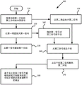
Fig. 1 is a flow diagram of a method for decoding a first packet and a second packet from a collision signal according to aspects of the present disclosure.
Fig. 2A and 2B illustrate an embodiment of a digital/digital de-clash (de-classer) according to aspects of the present disclosure.
Fig. 3 is a flow diagram of a method of de-colliding a signal that may be implemented with a digital/digital de-collider, according to aspects of the present disclosure.
FIG. 4 illustrates an offline training circuit for a de-collider, according to aspects of the present disclosure.
Fig. 5 is a flow diagram of a method of offline training a de-collider using an offline training circuit, according to aspects of the present disclosure.
FIG. 6 illustrates an online training circuit for a de-collider, according to aspects of the present disclosure.
FIG. 7 is a flow diagram of a method for online training of a de-collider, in accordance with aspects of the present disclosure.
Fig. 8A and 8B illustrate an embodiment of an analog/digital de-clash, according to aspects of the present disclosure.
Fig. 9 is a flow diagram of a method of de-colliding a signal that may be implemented with an analog/digital de-collider, according to aspects of the present disclosure.
To facilitate understanding, identical reference numerals have been used, where possible, to designate identical elements that are common to the figures. It is contemplated that elements disclosed in one embodiment may be beneficially utilized on other embodiments without specific recitation.
Detailed Description
Overview
One embodiment presented by the present disclosure provides a system for distortion cancellation, the system comprising: a first receiver path configured to digitize and amplify a first collision signal at a first gain to generate a first digital signal, the first collision signal comprising a first signal carrying a first packet and a second signal carrying a second packet, the first signal colliding with the second signal; a second receiver path configured to digitize and amplify a second conflicting signal at a second gain greater than the first gain to produce a second digital signal, the second conflicting signal comprising a conflicting first signal and a second signal; a non-linear estimator configured to determine a non-linear interference component of the first packet to the second packet from the first digital signal; a first receiver configured to decode a first packet from a first digital signal; a re-encoder configured to re-encode the first packet with the estimated first channel effect to produce an estimated signal; a linear estimator configured to determine linear interference components of the first packet to the second packet from the estimation signal; a subtractor configured to remove the linear interference component and the non-linear interference component from the second digital signal to generate an interference removed signal; and a second receiver configured to decode the second packet from the de-interfered signal.
One embodiment presented by the present disclosure provides a method for distortion cancellation, the method comprising: receiving a collision signal comprising a first signal carrying a first packet and a second signal carrying a second packet; amplifying and digitizing the collision signal into a first digital signal with a first gain, and amplifying and digitizing the collision signal into a second digital signal with a second gain greater than the first gain; determining a non-linear interference component of the first packet to the second packet from the first digital signal; decoding a first packet from a first digital signal; re-encoding the first packet into an estimated signal using a first estimated channel effect; calculating linear interference components of the first packet to the second packet from the estimated signal; removing a linear interference component and a non-linear interference component from the second digital signal to generate a de-interfered signal; and decoding the second packet from the de-interfered signal.
One embodiment presented by the present disclosure provides a computer-readable storage device comprising instructions that, when executed by a processor, perform operations for distortion cancellation, the operations comprising: receiving a collision signal comprising a first signal carrying a first packet and a second signal carrying a second packet; amplifying and digitizing the collision signal into a first digital signal with a first gain, and amplifying and digitizing the collision signal into a second digital signal with a second gain greater than the first gain; determining a non-linear interference component of the first packet to the second packet from the first digital signal; decoding a first packet from a first digital signal; re-encoding the first packet into an estimated signal using a first estimated channel effect; calculating linear interference components of the first packet to the second packet from the estimated signal; removing a linear interference component and a non-linear interference component from the second digital signal to generate a de-interfered signal; and decoding the second packet from the de-interfered signal.
One embodiment presented by the present disclosure provides a method for distortion cancellation, the method comprising: receiving a collision signal comprising a first component signal carrying a first packet and a second component signal carrying a second packet; amplifying and digitizing the collision signal according to a first gain to generate a first digital signal; extracting a nonlinear interference component of the first packet to the second packet in the collision signal from the first digital signal; extracting a linear interference component of the first packet to the second packet in the collision signal from the first digital signal; amplifying the conflicting signal according to a second gain greater than the first gain to produce a second signal; removing a non-linear interference component and a linear component interference from the second signal to generate a de-interfered signal; and decoding the second packet from the de-interfered signal.
One embodiment presented by the present disclosure provides a system for distortion cancellation, the system comprising: a first receiver path configured to digitize and amplify a first collision signal at a first gain to generate a first digitized signal, the first collision signal comprising a first signal carrying a first packet and a second signal carrying a second packet, the first signal colliding with the second signal; a first receiver configured to decode a first packet from a first digitized signal; a re-encoder configured to re-encode the first packet with the estimated first channel effect to produce an estimated signal; a linear estimator configured to determine linear interference components of the first packet to the second packet from the estimation signal; a digital-to-analog converter (DAC) configured to synthesize an analog linear interference component from the linear interference component; a non-linear estimator configured to determine from the first digitized signal a digital non-linear interference component of the first packet to the second packet; a second receiver path configured to amplify a second collision signal comprising the first signal and the second signal with a second gain greater than the first gain and apply a delay to produce a second amplified signal, wherein the delay is based on processing times of the first receiver, the re-encoder, the linearity estimator, and the DAC; a first subtractor configured to remove an analog linear interference component from the second amplified signal to generate a partial de-interference signal; an amplifier configured to apply a third gain to the partially de-interfered signal; a second subtractor configured to remove a digital nonlinear interference component from the partial interference removed signal to generate an interference removed signal; and a second receiver configured to decode the second packet from the de-interfered signal.
One embodiment presented by the present disclosure provides a method for distortion cancellation, the method comprising: receiving a collision signal comprising a first signal carrying a first packet and a second signal carrying a second packet; amplifying and digitizing the collision signal with a first gain into a first digital signal; decoding a first packet from a first digital signal; re-encoding the first packet using the first estimated channel effect to generate an estimated signal; calculating digital linear interference components of the first packet to the second packet from the estimated signal; synthesizing an analog linear interference component from the digital linear interference component; determining from the first digital signal a digital non-linear interference component of the first packet to the second packet; amplifying the conflicting signal at a second gain greater than the first gain to produce a second amplified signal; removing the analog linear interference component from the second amplified signal to produce a partial de-interference signal; applying a third gain to the partially de-interfered signal; removing a digital nonlinear interference component from the partial interference removed signal to generate an interference removed signal; and decoding the second packet from the de-interfered signal.
Example embodiments
To extract the individual packets included in the collision signal, the receiving device may perform various analyses to determine the effect of interference from the first packet on the second packet and the effect of interference from the second packet on the first packet in the collision signal. The receiving device may then remove the interference effects of the first and second packets from the collision signal to produce a de-interfered version of the collision signal from which the first and second packets may be decoded.
However, in a dynamic gain receiver that adjusts amplification of a received signal to the operating range of an associated analog-to-digital converter (ADC), when the amplitudes of the component signals of a colliding signal are different, the receiver may apply a dynamic gain that is appropriate for the first component signal but not for the second component signal to the colliding signal, which may result in the first and second packets being extracted and decoded with less fidelity than if the component signals were received separately. For example, if the dynamic gain of the first component signal is set to a higher value and a higher power second component signal collides with the first component signal, the receiver may over-amplify the colliding signal, which results in non-linear distortion and increases harmonics when interpreting the second component signal.
The present disclosure uses path diversity (spatial or radio frequency in various embodiments) with multiple different gain levels to extract individual packets from the colliding signals. Based on the characteristics (e.g., amplitude range) of the received signal, one signal path is provided with an aggressive (i.e., high) gain, while the other signal path is provided with a conservative (i.e., low) gain. The packets with higher power are extracted from the conservatively set signal path and used to determine the linear and nonlinear interference effects of the first packet on the second packet in the colliding signal. These effects are then removed from the aggressively set signal path and a packet with lower power is extracted from the resulting output. To improve the accuracy of the receiving device in determining the linear and non-linear components of the interference of the first packet to the second packet, various machine learning techniques may be used to train the non-linear estimator and the linear estimator online or offline.
Turning now to fig. 1, a method 100 for decoding a first packet and a second packet from a collision signal with higher fidelity is provided. At block 110, the de-collider receives a collision signal, which includes a first packet and a second packet. The de-collider decodes the first packet and the second packet from the collision signal on separate signal paths. In some embodiments, the de-collider receives the collided signal via a single antenna and separates the collided signal into a first signal path (from which the first packet is decoded) and a second signal path (from which the second packet is decoded). In other embodiments, the de-collider receives the colliding signal via two antennas as a first colliding signal carried on a first signal path from which the first packet is decoded and a second colliding signal carried on a second signal path from which the second packet is decoded.
At block 120, the de-collider applies a first gain (G1) to a first signal carried on the first signal path. The amplifier dynamically matches the amplitude of the first signal to the operating range of the ADC on the first signal path by applying a first radio frequency gain (G1-RF). In digitizing the first signal, the ADC in turn applies amplification of a first baseband gain (G1-BB) to the amplified first signal. The total gain of the first signal path may be expressed as the gain of the amplifier multiplied by the gain of the ADC (i.e., G1-G1-RF G1-BB). In some embodiments, the first gain (G1) is set to a predefined fraction of the second gain (G2) (according to block 150) applied to the second signal path. In other embodiments, the first gain is set based on the amplitude of the first component signal of the collision signal, which may be the earliest received component signal or the component signal with the largest amplitude when received.
At block 130, the de-collider decodes the first packet from the digitized first signal. In some embodiments, the first packet is output for use by various applications and components downstream from the de-collider.
At block 140, the de-collider determines interference of the first packet with the second packet in the colliding signal. In a digital/digital embodiment of the de-collider, the linear and non-linear interference components are determined as the digital effect of the first packet on the second packet in the colliding signal. In a digital/analog embodiment of the de-collider, the linear and non-linear interference components are determined as the digital effect of the first packet on the second packet in the collided signal, and the linear interference component is re-combined from the digital component to the analog component.
At block 150, the de-collider applies a second gain (G2) to the second signal carried on the second signal path. In some embodiments, the second amplifier sets the overall second gain to be greater than the overall first gain. In some embodiments, the second amplifier sets at least one of the second RF gain and the second baseband gain to be greater than the total first gain. Block 150 is performed in parallel with block 120-140 and may be performed prior to block 160 or in parallel with block 160 in various embodiments.
At block 160, the de-collider subtracts the linear interference component and the non-linear interference component of the first packet from the second signal (determined according to block 140).
In a digital/digital embodiment of the de-conflict device, the de-conflict device performs block 150 before proceeding to block 160. In a digital/digital embodiment of the de-classer, the amplifier dynamically matches the amplitude of the second signal to the operating range of the ADC on the second signal path by applying a second radio frequency gain (G2-RF). In digitizing the second signal, the ADC in turn applies amplification of a second baseband gain (G2-BB) to the amplified second signal. The total gain of the second signal path may be expressed as the gain of the amplifier multiplied by the gain of the ADC (i.e., G2-G2-RF G2-BB) and the second gain is greater than the first gain (i.e., G2> G1). In various embodiments, the de-collider sets the gains G1 and G2 (e.g., G2 x G1) relative to each other. The de-collider then subtracts the linear interference component and the non-linear interference component of the first packet from the amplified and digitized second signal to produce a de-interfered second signal.
In the digital/analog embodiment of the de-conflict device, the de-conflict device performs blocks 150 and 160 in parallel. In a digital/analog embodiment of the de-collider, an amplifier in the second signal path applies a gain (G2-RF) to the second signal, and the de-collider subtracts the analog linear interference component from the amplified analog second signal. After removing the linear interference component, the de-collider digitizes the amplified analog second signal by the ADC, which applies amplification by a second baseband gain (G2-BB) to the digitized second signal, and subtracts the digital non-linear interference component from the digitized second signal (determined according to block 140) to produce a de-interfered second signal. The total gain of the second signal path may be expressed as the gain of the amplifier multiplied by the gain of the ADC (i.e., G2-G2-RF G2-BB) and the second gain is greater than the first gain (i.e., G2> G1). In some embodiments, the gain G2-RF may be set such that the amplitude of the partially de-interfered analog second signal (from which the linear interference component has been removed) matches the operating range of the ADC on the second signal path.
At block 170, the de-collider decodes a second packet from the de-interfered second signal. In various embodiments, the de-collider uses the same receiver to decode the second packet, while in other embodiments, the de-collider uses two different receivers to decode the respective packets (according to block 130 and block 170). In some embodiments, the receiver is EVERSCALETMA receiver (available from cisco systems, san jose, california), but other decoding receivers may be used in other embodiments.
At block 180, the de-collider adjusts how to make an interference determination (per block 140) based on the difference between the de-interfered second signal (generated per block 160) and the re-encoded or known version of the second packet. The method 100 may then end or repeat from block 110.
Fig. 2A and 2B illustrate an embodiment of a digital/digital de-clash 200. Fig. 2A illustrates a de-collider 200 using a single shared antenna 205, and fig. 2B illustrates a de-collider 200 using a first antenna 205a and a second antenna 210B (generally, antenna 205). The antenna 205 is shown receiving component signals from a first signal source S1 and a second signal source S2. Several elements of digital/digital de-conflict 200 are implemented as hardware components (e.g., antenna 205, splitter 210), while other elements may be implemented as hardware, or as dedicated computing components (e.g., receiver 260, re-encoder 265, linear estimator 270) running software/firmware to perform the functions described herein.
In fig. 2A, a first component signal S from a first signal source S11(t) subject to a first channel condition h1(t) (e.g., interference, noise, path loss) and a second component signal S from a second signal source S22(t) subject to a second channel condition h2(t) influence such that antenna 205 receives conflicting signal sConflict(t) can be expressed according to equation 1.
sConflict(t)=h1(t)*s1(t)+h2(t)*s2(t) (1)
Separation of communication with antenna 205 in FIG. 2AThe collision signal s is transmitted by the device 210Conflict(t) into a first signal path and a second signal path. In various embodiments, splitter 210 is a Y-splitter that splits conflicting signals sConflict(t) into two substantially equal (+ -10%) amplitude signals, but in other embodiments the amplitudes of the first and second signals may be divided non-uniformly by the splitter 210. In the embodiment according to fig. 2A, the first collision signal s is carried on the respective first and second signal paths1c(t) and a second collision signal s2c(t) may thus be expressed according to equation 2a, and optionally according to equation 3 a.
sConflict(t)=s1c(t)+s2c(t)
(2a)
s1c(t)≈s2c(t)≈(h1(t)*s1(t)+h2(t)*s2(t))/2
(3a)
In fig. 2B, a first component signal S from a first signal source S11(t) subject to a first channel condition h1(t) (e.g., interference, noise, path loss) and a second component signal S from a second signal source S22(t) subject to a second channel condition h2(t) influence such that the first antenna 205a and the first signal path receive the first collision signal s1c(t) can be expressed according to formula 2 b. However, the second antenna 205b is spatially different from the first antenna 205a, and the first component signal s1(t) may be subject to different than the first channel condition h1(t) third channel condition h3(t) and the second component signal s2(t) may be subject to a different second channel condition h2(t) fourth channel condition h4(t) affects such that the second antenna 205b and the second signal path receive a second colliding signal s2c(t) can be expressed according to equation 3 b.
s1c(t)=h1(t)*s1(t)+h2(t)*s2(t)
(2b)
s2c(t)=h3(t)*s1(t)+h4(t)*s2(t)
(3b)
In fig. 2A and 2B, the first signal path includes a first node 215 and a second node 230, and a first amplifier 220a (generally, amplifier 220) and a first ADC225 a (generally, ADC 225) are connected between the first node 215 and the second node 230. The first amplifier 220a applies a gain of G1-RF to the first collision signal s1c(t) and the first ADC225 a will generate the first collision signal s1c(t) digitizing and applying the baseband gain of G1-BB to the collision signal s1c(t) to generate a first digitized signal s1d[n]. Similarly, the second signal path includes a third node 235 and a fourth node, and the second amplifier 220b and the second ADC225 b are connected between the third node 235 and the fourth node. The second amplifier 220b applies a gain of G2-RF to the second collision signal s2c(t) and the second ADC225 b converts the second collision signal s2c(t) digitizing and applying the baseband gain of G2-BB to the second collision signal s2c(t) to generate a second digitized signal s2d[n]. The total gain G1 on the first signal path may be expressed according to equation 4, and the total gain G2 on the second signal path may be expressed according to equation 5. The relationship between the first gain G1 and the second gain G2 may be expressed according to equation 6.
G1=G1-RF*G1-BB (4)
G2=G2-RF*G2-BB (5)
G1<G2 (6)
The de-collider 200 using multiple antennas 205 may optionally include multiple supplemental antennas 205 (which correspond to the same number of supplemental signal paths feeding the first receiver 260a and include amplifiers 220 and ADCs 225) depending on the number of spatially multiplexed packets intended to be received on the primary antenna (e.g., the first antenna 205a and the second antenna 205 b). In embodiments including supplemental antennas 205, the total number Q of antennas 205 employedAntenna with a shieldShould be at least equal to (but may be greater than) 1.5 x (m)1+m2) +1, wherein m1Is null in the first packetNumber of signals to be inter-multiplexed, and m2Is the number of spatial multiplexing signals in the second packet. As shown in fig. 2B, QAntenna with a shieldIs set to four because a packet (i.e., m) is received at the first antenna 205a11) and one packet (i.e., m) is received at the second antenna21) but in other embodiments more than four antennas 205 may be employed. Thus, as shown in FIG. 2B, the third signal path provides the third digitized signal s to the first receiver 260a3d[n]Is associated with the third antenna 205c, the third amplifier 220c and the third ADC225 c, and the fourth signal path is associated with providing the fourth digitized signal s to the first receiver 260a4d[n]Associated with the fourth antenna 205d, the fourth amplifier 220d, and the fourth ADC225 d. In embodiments with more packet collisions, more supplemental antennas 205 and corresponding supplemental signal paths (not shown) may be employed. As will be appreciated, each signal received and processed by the supplemental signal path is subject to a different channel effect hx(t) influence, so each supplemental signal path may apply a different gain G based on the operating range and received signal strength of the associated ADC225X(i.e. G)X-RF*GXBB), which can be set independently of G1 or G2.
Since the ADC225 may introduce non-linearity into the digitized signal when digitizing each conflicting signal, especially when the gain of the respective amplifier 220 amplifies the conflicting signal beyond the operating range of the ADC225, the de-collider 200 may set the second gain G2-RF based on the operating range of the second ADC225 b and the first gain G1-RF to a predetermined lower value based on G2-RF or based on the operating range of the first ADC225 a. The non-linearity of the individual signal paths can be regarded as the corresponding non-linear interference component f1NLOr f2NLBut is included in the corresponding digitized signal. Any noise in the respective signal path of a particular path, amplifier 220 and ADC225 may be present as component v1Or v2But is included in the corresponding digitized signal. Accordingly, the first digitized signal s is shown in fig. 2A and 2B, respectively1d[n]Can be expressed according to equation 7, and the second digitized signal s is shown in fig. 2A and 2B2d[n]Can be used forAccording to equation 8a or 8 b.
s1d[n]=G1*(h1[n]*s1[n]+h2[n]*s2[n])+f1NL(h1[n]*s1[n],h2[n]*s2[n])+v1(7)
s2d[n]=G2*(h1[n]*s1[n]+h2[n]*s2[n])+f2NL(h1[n]*s1[n],h2[n]*s2[n])+v2(8a)
s2d[n]=G2*(h3[n]*s1[n]+h4[n]*s2[n])+f2NL(h3[n]*s1[n],h4[n]*s2[n])+v2(8b)
The analog signal (and the analog signal-based formula) is represented herein as a function of time (represented as x (t)), and the digital signal (and the digital signal-based formula) is represented herein as a function of a time window or step size (represented as x [ n ]).
The interference determination path connects the first signal path at the second node 230 with the second signal path at the fourth node. The fourth node of the de-collider 200 comprises a first subtractor 240 and a second subtractor 245. A first digital delay 250a (generally, delay 250) and a non-linearity estimator 255 are connected between the second node 230 and the first subtractor 240. The first receiver 260a, the first re-encoder 265a and the linear estimator 270 are connected between the second node 230 and the second subtractor 245. In other embodiments, the order of the first subtractor 240 and the second subtractor 245 in the fourth node may be the reverse of the order shown in fig. 2A and 2B. In some embodiments, the first subtractor 240 and the second subtractor 245 are combined into a single component, while in other embodiments, the first subtractor and the second subtractor 245 are separate and distinct components from each other.
The disturbance determination path comprises two parallel trajectories: one trace is used to determine the linear interference component of the first packet to the second packet and one trace is used to determine the non-linear interference component of the first packet to the second packet.
To estimate the linear interference component, the de-collider 200 comprises a first receiver 260a (generally, receiver 260), a re-encoder 265 and a linear estimator 270 between the second node 230 and the second signal path. When a single shared antenna 205 is used, as shown in FIG. 2A, the first receiver 260a accepts the first digitized signal s1d[n]And decodes the first packet onto the first output as a decoded first packet d 1. When multiple antennas 205 are used, as shown in FIG. 2B, the first receiver 260a accepts the first digitized signal s1d[n]And a second digitised signal s2d[n]And any supplemental digitized signals to decode the first packet into a decoded first packet d 1. As shown in FIG. 2B, the first receiver 260a receives the third digitized signal s3d[n]And a fourth digitized signal s4d[n]As the supplemental digitized signal, other embodiments may receive more supplemental digitized signals. The re-encoder 265 re-encodes the decoded first packet d1 to estimate or approximate the first channel effect h resulting in the decoded first packet d11[n](e.g. using ) And a first component signal s1[n](e.g. using
 ) Is generated by a first estimating digital signal s1e[n]Which can be expressed according to equation 9.

As will be appreciated, the first channel effect and the associated estimated first channel effect (h)1[n]And ) May be different from each other. Similarly, the first component signal and the associated estimated first component signal(s)1[n]And
 ) May be different from each other. The difference between the first channel effect and the estimated and actual values of the first component signal may be noise (e.g., v) in the first signal path1Or h2[n]*s2[n]) Or nonlinearity introduced by the first ADC225 a (e.g., f)1NL[n]) And the re-encoder 265 may be more accurate when the signal-to-noise ratio (SNR) on the first signal path is lower and the receiver 260 may decode the first packet more accurately.
The linear estimator 270 receives the first estimated digital signal s1e[n]And applies a gain G2 to the first estimated signal s1e[n]Such that the de-collider 200 may remove the first component signal s from the second signal path1(estimated) influence of (t). The linearity estimator 270 may be trained either off-line (i.e., using a known input signal in accordance with the method 500 discussed with respect to fig. 5) or on-line (i.e., using a "live" or unknown input signal in accordance with the method 700 of fig. 7).
To estimate the non-linear interference component, the de-collider 200 comprises a first digital delay 250a and a non-linear estimator 255 connected between the second node 230 and the second signal path. In various embodiments, the first digital delay 250a may be located before or after the non-linearity estimator 255 and synchronize the output of the determination of the non-linear interference component with the determination of the linear interference component such that the second signal path is derived from the second digitized signal s2d[n]The non-linear and linear interference components of the same time window are removed. For example, if the non-linearity estimator 255 is at time t0Determining a first digitized signal s1d[n]And the first receiver 260, the re-encoder 265 and the linearity estimator 270 may be at time t1Processing a first digitised signal s1d[n]To generate a linear interference component, the first digital delay device 250a delays the output of the non-linear interference component by (t)1-t0). In various embodiments, the first digital delay 250a may be a discrete component or an integrated component (e.g., a first-in-first-out register).
In various embodiments, the non-linearity estimator 255 is a feed-forward artificial neural network (FFANN). Non-linear estimator 255 receive the first digitized signal s over m time segments n1d[n]And using s on the first signal path1d[n]To s1d[n-m]To estimate the first component signal s on the second signal path1[n]And a second component signal s2[n]Of the non-linear interference component. When receiving s1d[n]When the new value of (c) is reached, the old value is cycled off (e.g., time t)0S of1d[n]Becomes time t1S of1d[n-1]Which becomes time t2S of1d[n-2]Etc.). The non-linear estimator 255 weights the values of the various inputs and the values of the various hidden nodes that associate the various inputs together and then generates an estimated non-linear interference component for the second line In the de-conflict device 200 of figure 2A,
 can represent
 Whereas in the de-collider of figure 2B,
 can represent
 The de-collider 200 may train the weights used by the
 non-linear estimator 255 either off-line (i.e., using a known input signal according to the method 500 discussed with respect to fig. 5) or on-line (i.e., using a "live" or unknown input signal according to the method 700 of fig. 7).
The first subtractor 240 includes a first minuend input that accepts the second digitized signal s from the second ADC225 b2d[n]And a first subtrahend input that accepts the estimated nonlinear interference component from the nonlinear estimator 255 To digitize the signal s from the second2d[n]Removing non-linear interference components
 The
The second subtractor 245 includes a second minded input that accepts the second digitized signal s from the first differential output of the first subtractor 2402d[n](subtracting the nonlinear interference component ) And a second subtrahend input that accepts the estimated linear interference component G from the
 linear estimator 2702*s1e[n]To digitize the signal s from the second2d[n]The nonlinear interference component is removed. Each subtractor may be a multiplexer that provides a signal at the subtrahend input to negatively (negatively) interfere with (e.g., cancel a portion of) the signal input at the subtrahend input. The second differential output of the second subtractor 245 generates the de-interfered second signal s2i[n]Which may be represented by equation 10a or 10B according to fig. 2A or 2B, respectively, where R represents f on the second signal path2NL[n]Residual interference (i.e. of )。
)。
s2i[n]=G2*h2[n]*s2[n]+v2+R
(10a)
s2i[n]=G2*h4[n]*s2[n]+v2+R
(10b)
The second receiver 260b receives the de-interfered second signal s2i[n]And from the de-interfered second signal s2i[n]As decoded first packet d2 onto a second output. In various embodiments, the first receiver 260a and the second receiver 260b are separate input channels of a single receiver 260, while in other embodiments, the first receiver 260a and the second receiver 260b are discrete receivers 260.
FIG. 3 is a diagram that may be used in connection with2A and 2B, a flow diagram of a method 300 for de-colliding a signal implemented by the de-collider 200. Method 300 begins at block 310, where de-collider 200 receives a colliding signal (e.g., s)Conflict(t)) comprising a first component signal (e.g., s) carrying a first packet1(t)) and a second component signal (e.g., s) carrying a second packet2(t)). In some embodiments, the colliding signal is received at shared antenna 205 and split into a first colliding signal (e.g., s) on a first signal path1c(t)) and a second collision signal (e.g., s) on a second signal path2c(t)). In other embodiments, colliding signals are received by different antennas 205 independently on each signal path. For example, the collision signal is received at the first antenna 205a as a first collision signal on a first signal path having a first channel effect (e.g., h 1) from a first source (e.g., S1) affecting a first packet1(t)) and a second channel effect (e.g., h) from a second source (S2) affecting a second packet2(t)), and the colliding signal is received at the second antenna 205b as a second colliding signal on a second signal path having a third channel effect (e.g., h) from the first source affecting the first packet3(t)) and a fourth channel effect from the second source affecting the second packet (e.g., h)4(t))。
At block 320, the de-collider 200 amplifies and digitizes the collided signal according to a first gain (e.g., G1) on a first signal path including the first amplifier 220a and the first ADC225 a to generate a first digital signal (e.g., s) in accordance with a first gain1d[n]). The de-collider 200 (on a second signal path including the second amplifier 220b and the second ADC225 b) amplifies and digitizes the collided signal according to a second gain (e.g., G2) that is greater than the first gain to produce a second digital signal (e.g., s2d[n])。
At block 330, the de-collider 200 extracts from the first digital signal a non-linear component of the interference of the first packet to the second packet in the collided signal (e.g., or
or In various embodiments, the de-collider 200 uses FFANN as the
 non-linearity estimator 255 to estimate the real and imaginary components of a given time or time window encoding the non-linear interference components of the first packet versus the second packet. In various embodiments, the output of the non-linear interference component estimated according to block 330 is time delayed (according to blocks 340 and 360 in method 300) based on the processing time to extract the estimated linear interference component such that the linear and non-linear interference components are removed from the second collision signal at the same time period (according to block 360 in method 300).
At block 340, the de-collider 200 decodes the first packet from the first digital signal to produce a decoded first packet (e.g., d 1). In various embodiments, decoding the first packet is provided as a first output of the de-collider 200. For example, receiver 260 (e.g., EVERSCALE)TMA receiver) may attempt to decode both the first signal and the second signal from the colliding signal.
At block 350, the de-collider 200 extracts a linear interference component (e.g., G) of the first packet to the second packet in the collided signal2*s1e[n]). To estimate the linear interference component, de-collider 200 re-encodes the decoded first packet into a first estimated digital signal (e.g., s)1e[n]) Which approximates the first channel effect received in the colliding signals (e.g., ) And a first component signal (e.g.,
 ) Both, and feeds the estimated digital signal to the
 linearity estimator 270. The linear estimator 270 extracts the linear component of the interference of the first packet to the second packet in the collision signal from the estimated digital signal.
At block 360, the de-collider 200 removes the non-linear interference component and the linear component interference from the second digital signal to produce a de-interfered signal (e.g., s)1i[n]). In thatIn various embodiments, the first subtractor 240 removes the nonlinear interference component and the second subtractor 245 removes the linear interference component. In other embodiments, the first subtractor 240 removes the linear interference component and the second subtractor 245 removes the non-linear interference component. In a further embodiment, a single subtractor 240 removes both linear and non-linear interference components.
At block 370, the de-collider 200 decodes the second packet from the de-interfering signal into a second decoded packet (e.g., d 2). In various embodiments, the second decoded packet is provided as a second output of the de-collider 200. For example, receiver 260 (e.g., EVERSCALE)TMA receiver) may attempt to decode both the first signal and the second signal from the colliding signal. The method 300 may then end.
Fig. 4 illustrates an offline training circuit 400 of the digital/digital de-conflict 200 described with respect to fig. 2A and 2B or the analog/digital de-conflict 800 described with respect to fig. 8A and 8B. Although offline training circuit 400 shown in fig. 4 is shown connected to digital/digital de-collider 200, any reference to digital/digital de-collider 200 or components thereof (e.g., antenna 205, non-linearity estimator 255) may be understood as applying to analog/digital de-collider 800 or components thereof (e.g., antenna 805, non-linearity estimator 855). In various embodiments, offline training circuit 400 is provided by external test equipment during initial setup and training of the de-collider 200, or may be an integrated component of the de-collider 200, to which the de-collider 200 may selectively engage to initiate an offline training session.
As shown, bypass path 410 connects first signal source S1 to the input of linearity estimator 270 (bypassing first receiver 260a and re-encoder 265 of FIGS. 2A and 2B). In other embodiments, bypass path 410 connects first node 215 with the input of linearity estimator 270. The bypass path 410 carries a known simulated first channel effect h1(t) the first known signal s of influence1(t) without the first receiver 260a and re-encoder 265 having to digitize the first signal s1d[n]Interprets it as a first decoded packet d1 and re-encodes the first decoded packet d1 into a first estimated digital signal s1e[n]
Removal (temporarily or switchably) of first receiver 260a and re-encoder 265 from de-collider 200 via bypass path 410 may affect the relative speed at which non-linear estimator 255 and linear estimator 270 produce outputs. Thus, the de-collider 200 may adjust the length of the delay applied by the first digital delay 250 when the offline training circuit 400 is active, relative to when the offline training circuit 400 is inactive.
In embodiments where linear estimator 270 is not (re) trained in an offline training session, bypass path 410 may bypass linear estimator 270 and be directly connected to the subtrahend input of second subtractor 245, rather than the output from linear estimator 270.
By digitizing the signal s from the second2d[n]Subtracting the outputs of the linear estimator 270 and the non-linear estimator 255, the first collision signal s is processed as discussed with respect to fig. 2A and 2B according to equation 10a or 10B, respectively1c(t) and a second collision signal s2c(t) to generate a second de-interference signal s2i[n]。
As shown, the check path 420 connects the second signal source S2 to the comparator 415.In other embodiments, the check path 420 connects the third node 235 with the comparator 415. In embodiments where training uses a single shared antenna 205 (e.g., as in fig. 2A), the inspection path 420 carries a known simulated second channel effect h2(t) the second known signal s of influence2(t) of (d). In embodiments where training uses the first antenna 205a and the second antenna 205B (e.g., as in fig. 2B), the inspection path 420 carries a known simulated fourth channel effect h4(t) the second known signal s of influence2(t)。


FIG. 5 is a flow diagram of a method 500 for offline training the de-collider 200/800, which may be implemented using the de-collider 200/800 of the offline training circuit 400 described in relation to FIG. 4. The method 500 begins at block 510, where a first known signal source feeds a first known signal carrying a first known packet to the channel simulator 405 and a second known signal source feeds a second known signal carrying a second known packet to the channel simulator 405.
At block 520, offline training circuit 400 bypasses first receiver 260a and re-encoder 265 to provide the first known signal directly to linear estimator 270 to determine a linear interference component of the first known signal to the second known signal.
At block 530, the channel simulator 405 feeds the colliding known signals onto the first and second signal paths as respective first and second colliding signals (e.g., s)1c(t) and s2c(t)). The channel simulator 405 places a first conflicting signal on a first signal path at the first node 215, where a first channel effect (e.g., h) is simulated1(t)) affects the first known signal and models a second channel effect (e.g., h)2(t)) affects the second known signal. In some embodiments (e.g., to train the single antenna de-collider 200/800), the channel simulator 405 places a second colliding signal on the second signal path at the third node 235 as a first colliding signal, wherein the same simulated first and second channel effects affect the first and second known signals. In other embodiments (e.g., to train the multi-antenna de-collider 200/800), the channel simulator 405 places a second signal on a second signal path at a third node 235, where a third channel effect (e.g., h) is simulated3(t)) affects the first known signal and simulates a fourth channel effect (e.g., h)4(t)) affects the second known signal.
At block 540, the de-collider 200 extracts (trains) a non-linear interference component from the first colliding signal (e.g., or
or In normal operation (e.g., according to
 method 300 or method 900), the de-collider 200 amplifies and digitizes the first collision signal on the first signal path (e.g., to produce a first digitized signal s)1d[n]) And feeds the digitized first signal to the non-linearity estimator 255. In various embodiments, the de-collider 200 uses FFANN as the non-linearity estimator 255 to estimate the real and imaginary components of a given time or time window encoding the non-linear interference components of the first packet versus the second packet. In various embodiments, during normal operationIn the meantime, the output of the non-linear interference component is delayed based on the processing time to extract the estimated linear interference component (e.g., according to blocks 340 and 360 in methods 300), but the delay in method 500 may be set to a shorter time than used in methods 300 and 900 because the offline training circuit 400 bypasses the first receiver 260a and the re-encoder 265.
At block 550, the de-collider 200 removes (trains) the linear and non-linear interference components from the second collided signal on the second signal path to produce (trains) a de-interfered second signal. In various embodiments, the linear interference component is removed from the analog second collision signal as an analog signal before digitizing the second collision signal (as a partially de-interfered signal) and removing the non-linear interference component. In other embodiments, the linear and non-linear interference components are removed from the digital second collision signal as a digital signal.
At block 560, offline training circuit 400 combines the second known signal, the channel effect (e.g., h)2(t) or h4(t)), and the gain applied on the second signal path is fed to the comparator 415, and the de-collider 200 feeds the de-interfered second signal to the comparator 415. The comparator 415 determines the difference between the de-interfered second signal and the ideal second known signal (e.g., residual error or noise on the second signal path) based on the known channel effect and the gain applied to the signal. At block 570, the comparator 415 adjusts the non-linear estimator 255 via the inverse error propagation of the difference to the neural network. At block 580, the comparator adjusts the linear estimator 270 via the minimum mean square error. The method 500 may then end or repeat additional training rounds.
Fig. 6 illustrates an online training circuit 600 of the digital/digital de-conflict 200 described with respect to fig. 2A and 2B or the analog/digital de-conflict 800 described with respect to fig. 8A and 8B. Although the online training circuit 600 shown in fig. 6 is shown connected to the digital/digital de-collider 200, any reference to the digital/digital de-collider 200 or components thereof (e.g., antenna 205, linearity estimator 270) may be understood as applying to the analog/digital de-collider 800 or components thereof (e.g., antenna 805, non-linearity estimator 855).
The live signal (with values not known to the de-collider 200 prior to decoding and de-collision) is decoded and de-collided, as discussed with respect to the method 300 in fig. 3 or the method 900 in fig. 9, and the resulting output is used to train the non-linear estimator 255 and the linear estimator 270. Although fig. 6 shows that online training circuit 600 is applied to the output of de-collider 200 using a single shared antenna 205 as in fig. 2A, online training circuit 202 may be applied to the output of de-collider 200 using multiple antennas 205 as in fig. 2B (as well as analog/digital de-collider 800 shown in fig. 8A and 8B).
The on-line training circuit 600 accepts the decoded second packet d2 from the de-collider 200 and de-interferes with the second signal s2i[n]As an input. The second re-encoder 610 re-encodes the decoded second packet d2 to estimate or approximate the second or fourth channel effect h of the decoded second packet d22[n]Or h4[n](each as Or
Or ) And a second component signal s2[n](e.g. using
 ) Second estimation digital signal s2e[n]Which may be expressed according to equation 11a in an embodiment using one
 antenna 205 or may be expressed according to equation 11b in an embodiment using a plurality of antennas 205.


The second digital delay 605 receives the de-interfered second signal s2i[n]And then it is combined with a second re-encoder 6The output of 10 is synchronized to take into account the time at which the second receiver 260b and the second re-encoder 610 process the decoded second packet d 2. For example, if the de-collider 200 is at time t0Outputting a second interference-removed signal s2i[n]And the second receiver 260b and the second re-encoder 610 at time t1Processing the second de-interference signal s2i[n]To generate a second estimated digital signal s2e[n]The second digital delay 605 will then de-interfere the second signal s2i[n]Output delay (t) to comparator 6151-t0). In various embodiments, the second digital delay 605 may be a discrete or integrated component (e.g., a first-in-first-out register).

Fig. 7 is a flow diagram of a method 700 for online training of a digital/digital de-conflict 200 or an analog/digital de-conflict 800, which may be implemented with the de-conflict 200 in an online training arrangement as described with respect to fig. 6. Method 700 begins at block 710, where online training circuit 600 receives a decoded second packet (e.g., d2) and a de-interfered second signal (e.g., s2) from the output of normal operation of de-collider 2002i[n]) (e.g., method 300 or method 900). During online training, the de-collider 200 receives live signals, theseThe live signal has values unknown to the de-collider 200 prior to decoding and de-collision.
At block 720, the in-line training circuit 600 re-encodes the decoded packet to approximate the second/fourth channel effects received in the collision signal (e.g., or
or ) And a second component signal (e.g.,
 ) Second estimation digital signals (e.g. s) of both2e[n])。
At block 730, the online training circuit 600 compares the second estimated digital signal to the second de-interfered signal. In various embodiments, the second packet is decoded and re-encoded into the second estimated digital signal s in order to compensate2e[n]The desired time, the on-line training circuit 600 delays (e.g., via digital delay 605) the second de-interference signal s2i[n]To match the time window of each signal. The comparator 615 determines a difference between the second estimated digital signal and the second de-interference signal. In block 740, the comparator 415 adjusts the non-linear estimator 255 via the inverse error propagation of the difference to the neural network. At block 750, the comparator 615 adjusts the linear estimator 270 via the minimum mean square error. The method 700 may then end or repeat additional training rounds.
Fig. 8A and 8B illustrate an embodiment of an analog/digital de-clash 800. Fig. 8A illustrates a de-collider 800 using a single shared antenna 805, and fig. 8B illustrates a de-collider 800 using a first antenna 805a and a second antenna 805B (generally, antennas 805). Antenna 805 is shown receiving component signals from a first signal source S1 and a second signal source S2. Several elements of the analog/digital de-conflict 800 are implemented as hardware components (e.g., antenna 805, splitter 810), while other elements may be implemented as hardware, or as dedicated computing components (e.g., receiver 860, re-encoder 865, linearity estimator 870) running software/firmware to perform the functions described herein.
In fig. 8A, a first component signal S from a first signal source S11(t) subject to a first channel condition h1(t) (e.g., interference, noise, path loss) and a second component signal S from a second signal source S22(t) subject to a second channel condition h2(t) influence such that antenna 805 receives conflicting signals SConflict(t) can be expressed according to equation 12.
SConflict(t)=h1(t)*s1(t)+h2(t)*s2(t)
(12)
In fig. 8A, a separator 810 in communication with antenna 805 will separate colliding signals SConflict(t) into a first signal path and a second signal path. In various embodiments, splitter 810 is a Y-splitter that splits conflicting signals SConflict(t) into two substantially equal (+ -10%) amplitude signals, but in other embodiments the amplitudes of the first and second signals may be divided non-uniformly by the splitter 810. In the embodiment shown in FIG. 8A, the first collision signal s is carried on respective first and second signal paths1c(t) and a second collision signal s2c(t) may thus be expressed according to equation 13a, and optionally according to equation 14 a.
SConflict(t)=s1c(t)+s2c(t)
(13a)
s1c(t)≈s2c(t)≈0.5(h1(t)*s1(t)+h2(t)*s2(t)
(14a)
In fig. 8B, a first component signal S from a first signal source S11(t) subject to a first channel condition h1(t) (e.g., interference, noise, path loss) and a second component signal S from a second signal source S22(t) subject to a second channel condition h2(t) influence such that the first antenna 805a and the first signal path receive the first collision signal s1c(t) can be expressed according to equation 13 b. However, the second antenna 805b are spatially distinct from the first antenna 805a, and the first component signal s1(t) may be subject to different than the first channel condition h1(t) third channel condition h3(t) and the second component signal s2(t) may be subject to a different second channel condition h2(t) fourth channel condition h4(t) influence such that second antenna 805b and second signal path receive second collision signal s2c(t) can be expressed according to equation 14 b.
s1c(t)=h1(t)*s1(t)+h2(t)*s2(t)
(13b)
s2c(t)=h3(t)*s1(t)+h4(t)*s2(t)
(14b)
In fig. 8A and 8B, the first signal path includes a first node 815 and a second node 830, and a first amplifier 820a (generally, amplifier 820) and a first ADC825 a (generally, ADC 825) are connected between the first node 815 and the second node 830. The first amplifier 820a applies a gain of G1-RF to the first collision signal s1c(t) and the first ADC825 a combines the first collision signal s1c(t) digitizing and applying the baseband gain of G1-BB to the collision signal s1c(t) to generate a first digitized signal s1d[n]. The total gain G1 on the first signal path may be expressed according to equation 15.
G1=G1-RF*G1-BB
(15)
The non-linearity of the individual signal paths can be regarded as the corresponding non-linear interference component f1NLOr f2NLBut is included in the corresponding digitized signal. Any noise in the respective signal path of a particular path, amplifier 820 and ADC825 may be present as component v1Or v2But is included in the corresponding digitized signal. Thus, the first digitized signal s in fig. 8A and 8B1d[n]Can be expressed according to equation 16.
s1d[n]=G1*(h1[n]*s1[n]+h2[n]*s2[n])+f1NL(h1[n]*s1[n],h2[n]*s2[n])+v1
(16)
In contrast to the first signal path, the second signal path includes a third node 835 and a fourth node of the first subtractor 840a, and the second amplifier 820b and the analog delay 850a (generally, the delay 850) are connected between the third node 835 and the fourth node. The second amplifier 820b applies a gain of G2-RF to the second collision signal s2c(t) and the analog delay 850a synchronizes the output of the second amplifier 820b with the determination of the linear interference component such that the second signal path is from the second collision signal s2c(t) removing linear interference components of the same time window. In various embodiments, analog delay 850a may be located before or after second amplifier 820 on the second signal path.
The de-collider 800 using multiple antennas 805 may optionally include multiple supplemental antennas 805 (which correspond to the same number of supplemental signal paths feeding the first receiver 860a and include amplifiers 820 and ADCs 825) depending on the number of spatially multiplexed packets intended to be received on the primary antenna (e.g., the first antenna 805a and the second antenna 805 b). Total number Q of antennas 805 employedAntenna with a shieldShould be at least equal to (but may be greater than) 1.5 x (m)1+m2) +1, wherein m1Is the number of spatially multiplexed signals in the first packet, and m2Is the number of spatially multiplexed signals in the second packet. As shown in FIG. 8B, QAntenna with a shieldIs set to four because a packet (i.e., m) is received at the first antenna 805a11) and receives one packet (i.e., m) at the second antenna 805b21) but in other embodiments more than four antennas 205 may be employed. Thus, as shown in FIG. 8B, the third signal path may provide a third digitized signal s to the first receiver 860a3d[n]Is associated with the third antenna 805c, the third amplifier 820c and the third ADC825 c, and the fourth signal path is associated with providing a fourth digitized signal s to the first receiver 860a4d[n]Is associated with the fourth antenna 805d, the fourth amplifier 820d and the fourth ADC825 d. In embodiments with more packet collisions, more supplemental days may be employedLine 805 and a corresponding supplemental signal path (not shown). As will be appreciated, each signal received and processed by the supplemental signal path is subject to a different channel effect hx(t) influence, so each supplemental signal path may apply a different gain G based on the operating range and received signal strength of the associated ADC825X(i.e. G)X-RF*GXBB), which can be set independently of G1 or G2. Although not shown, the supplemental signal path may include analog or digital delay elements to time align the input to the first receiver 260a with the output from the first ADC825 a or the second ADC825 b.
The analog interference determination path connects the first signal path at the second node 830 with the second signal path at the fourth node/first subtractor 840 a. A first receiver 860a (generally, receiver 860), a first re-encoder 865a (generally, re-encoder 865), a linearity estimator 870, an optional up-sampler 895, and a digital-to-analog converter (DAC)845 are coupled between the second node 830 and the first subtractor 840 a.
When a single shared antenna is used, as shown in FIG. 8A, first receiver 860a accepts first digitized signal s1d[n]And decodes the first packet onto the first output as a decoded first packet d 1. When multiple antennas 205 are used, as shown in FIG. 8B, the first receiver 260a accepts the first digitized signal s1d[n]And a second digitised signal s2d[n]And any supplemental digitized signals to decode the first packet into a decoded first packet d 1. As shown in FIG. 2B, the first receiver 260a receives the third digitized signal s3d[n]And a fourth digitized signal s4d[n]As the supplemental digitized signal, other embodiments may receive more supplemental digitized signals. The first re-encoder 865a re-encodes the decoded first packet d1 into an estimate or approximation resulting in the first channel effect h of the decoded first packet d11[n](e.g. using ) And a first component signal s1[n](e.g. using
 ) Is generated by a first estimating digital signal s1e[n]Which can be expressed according to equation 17.

(17)
As will be appreciated, the first channel effect and the associated estimated first channel effect (h)1[n]And ) May be different from each other. Similarly, the first component signal and the associated estimated first component signal(s)1[n]And
 ) May be different from each other. The difference between the first channel effect and the estimated and actual values of the first component signal may be noise (e.g., v) in the first signal path1Or h2[n]*s2[n]) Or nonlinearity introduced by the first ADC825 a (e.g., f)1NL[n]) And the re-encoder 865 may be more accurate when the SNR on the first signal path is low and the receiver 860 may decode the first packet more accurately.
The linear estimator 870 receives the first estimating digital signal s1e[n]And applies a gain G2-RF to the first estimated signal s1e[n]Such that the de-collider 800 may remove the first component signal s from the second signal path1(estimated) influence of (t). The linearity estimator 870 may be trained offline (i.e., using a known input signal in accordance with the method 500 discussed with respect to fig. 5) or online (i.e., using a "live" or unknown input signal in accordance with the method 700 of fig. 7).
An optional upsampler 895 increases the sampling rate of the output of the linear estimator 870. In some embodiments, the upsampler 895 produces an extended version in which the upsampled value matches the output value, changing when the output value changes. E.g. from time t0To t3The output of the linear estimator 870 may be s1e[n0]1/TRUE, and from time t4To t7Can be s1e[n1]0/FALSE and the upsampler 895 goes from time t4-t7Generating a spreading sequence [1,1,1,1,0,0]Which includes more values (e.g., four 1/TRUE instances and four 0/FALSE instances, rather than one instance each) to allow the DAC 845 to process more data when synthesizing an analog signal from a digital signal.

(18)
The gain G2-RF applied by the second amplifier 820b in various embodiments is selected to be greater than the gain G1 applied in the first signal path to remove the analog linear interference component s by the first subtractor 840a1e(t) while partially de-interfering with the second signal s2p(t) maintaining the second collision signal s2cThe relative positive/negative values of (t) (i.e., G1 < G2-RF).
The digital interference determination path connects the first signal path at the second node 830 with the second signal path at the fifth node/second subtractor 840 b. The digital interference determination path includes a first digital delay 850b and a non-linearity estimator 855. In various embodiments, the firstThe digital delay 850b may be located before or after the non-linearity estimator 855 and synchronizes the output of the determination of the non-linear interference component with the determination of the linear interference component on the analog interference determination path such that the second signal path is derived from the second collision signal s2c(t) removing non-linear and linear interference components of the same time window. For example, if the non-linearity estimator 855 is at time t0Determining a first digitized signal s1d[n]And the analog interference determination path (including the first subtractor 840a and the second ADC825b) is required up to time t1From the second collision signal s2c(t) removing the first composite signal s1s(t) and digitizing the output into a second digitized signal s2d[n]The first digital delayer 850b delays (t) the output of the nonlinear interference component1-t0). In various embodiments, the first digital delay 850b may be a discrete component or an integrated component (e.g., a first-in-first-out register).
In various embodiments, the non-linearity estimator 855 is FFANN. The non-linearity estimator 855 receives the first digitized signal s over m time segments n1d[n]And using s on the first signal path1d[n]To s1d[n-m]To estimate the first component signal s on the second signal path1[n]And a second component signal s2[n]Of the non-linear interference component. When receiving s1d[n]When the new value of (c) is reached, the old value is cycled off (e.g., time t)0S of1d[n]Becomes time t1S of1d[n-1]Which becomes time t2S of1d[n-2]Etc.). The non-linear estimator 855 weights the values of the respective inputs and the values of the respective hidden nodes that associate the respective inputs together, and then generates an estimated non-linear interference component of the second line In the de-classer 800 of figure 8A,
 can represent
 Whereas in the de-collider of figure 8B,
 can represent
 The de-collider 800 may train the weights used by the
 non-linear estimator 855 either off-line (i.e., using a known input signal in accordance with the method 500 discussed with respect to fig. 5) or on-line (i.e., using a "live" or unknown input signal in accordance with the method 700 of fig. 7).
The collision signal s on the second signal path is subtracted from the first subtractor 840a2c(t) after removing the analog linear interference component, the second ADC825b will partially remove the interference signal s2p(t) digitising and partially de-disturbing the digitised part by the signal s2p[n]Fed to the subtracted input of the second subtractor 840 b. The second subtractor 840b receives the nonlinear interference component f from the nonlinear estimator 8552NL[n]And generating a de-interference signal s at the differential output2i[n]Which may be represented by equation 19a or equation 19B according to fig. 8A or fig. 8B, respectively, where R represents f on the second signal path2NL[n]Residual interference (i.e. of )。
)。
s2i[n]=G2*h2[n]*s2[n]+v2+R
(19a)
s2i[n]=G2*h4[n]*s2[n]+v2+R
(19b)
By digitizing the second collision signal s2c(t) removing the linear interference component as an analog signal s1e(t), the de-collider 800 may set a gain G2-RF (e.g., a second gain) such that the second signal s is partially de-interfered with2p(t) is matched to the operating range of the second ADC825b, allowingThe de-collider uses a larger portion of the second ADC825b range (than the second collision signal s, which is to be digitized version)2d[n]Compared to the embodiment fed to subtractor 840) to reduce the noise v introduced by the second ADC825b2. Furthermore, the gain G2-BB (e.g., the third gain) applied by the second ADC825b is selected such that once the non-linear interference is removed, the resulting de-interfered second signal s2i(t) maintaining the second collision signal s2cRelative positive/negative values of (t). In some embodiments, the gain G2-BB is set to be greater than the gain G1 applied to the first signal path according to equation 20, while in other embodiments, the gain G2-BB is set according to equation 21.
G1<G2-BB
(20)
min(G2-BB*s2p(t))–max(G1*s1c(t))>0
(21)
The second receiver 860b receives the de-interfered second signal s2i[n]And will come from the de-interfering second signal s2i[n]As decoded first packet d2 onto a second output. In various embodiments, first receiver 860a and second receiver 860b are separate input channels of a single receiver 860, while in other embodiments, first receiver 860a and second receiver 860b are discrete receivers 860.
Fig. 9 is a flow diagram of a method 900 for de-colliding a signal that may be implemented with the de-collider 200 described with respect to fig. 8A and 8B. Method 900 begins at block 910, where de-collider 800 receives a colliding signal (e.g., s)Conflict(t)) comprising a first component signal (e.g., s) carrying a first packet1(t)) and a second component signal (e.g., s) carrying a second packet2(t)). In some embodiments, the colliding signal is received at shared antenna 205 and split into a first colliding signal (e.g., s) on a first signal path1c(t)) and a second collision signal (e.g., s) on a second signal path2c(t)). In other embodiments, colliding signals are received by different antennas 205 independently on each signal path. For example, the collision signal is in the firstReceived at antenna 205a as a first colliding signal on a first signal path having a first channel effect (e.g., h) from a first source (e.g., S1) affecting a first packet1(t)) and a second channel effect (e.g., h) from a second source (S2) affecting a second packet2(t)), and the colliding signal is received at the second antenna 205b as a second colliding signal on a second signal path having a third channel effect (e.g., h) from the first source affecting the first packet3(t)) and a fourth channel effect from the second source affecting the second packet (e.g., h)4(t))。
At block 915, the de-collider 800 amplifies and digitizes the collided signal according to a first gain (e.g., G1) on a first signal path including a first amplifier 820a and a first ADC825 a to generate a first digital signal (e.g., s1)1d[n])。
At block 920, the de-collider 200 extracts from the first digital signal a non-linear component of the interference of the first packet to the second packet in the collided signal (e.g., or
or In various embodiments, the de-collider 800 uses FFANN as a
 non-linearity estimator 855 to estimate the real and imaginary components of a given time or time window that encodes the non-linear interference components of the first packet versus the second packet. In various embodiments, the output of the non-linear interference component estimated according to block 920 is time delayed (according to block 925 and 950 in method 900) based on the processing time to extract the estimated linear interference component such that the linear and non-linear interference components are removed from the second collision signal within the same time period (according to blocks 945 and 955 in method 900).
At block 925, the de-collider 800 decodes the first packet from the first digital signal to produce a decoded first packet (e.g., d 1). In various embodiments, decoding the first packet is provided as a first output of the de-collider 800. For example, receiver 860 (e.g., EVERSCALE)TMReceivingA machine) may attempt to decode both the first signal and the second signal from the colliding signal.
At block 930, the de-collider 800 extracts a linear interference component (e.g., G) of the first packet to the second packet in the collided signal2*s1e[n]). To estimate the linear interference component, de-collider 800 re-encodes the decoded first packet into a first estimated digital signal (e.g., s)1e[n]) Which approximates the first channel effect received in the colliding signals (e.g., or
or ) And a first component signal (e.g.,
 ) Both, and feed the estimated digital signal to the
 linearity estimator 870. The linear estimator 870 extracts a linear component of the interference of the first packet to the second packet in the collision signal from the estimated digital signal.
At block 935, the de-collider 800 will carry the digital signal (e.g., s) of the digital linear interference component1e[n]) Upsampled and synthesized into an analog linear interference component (e.g., s)1e(t))。
At block 940, the de-collider 800 amplifies and delays the collided signal (e.g., s) according to a second RF gain (e.g., G2-RF) greater than the first gain on a first signal path including the second amplifier 820b and the second ADC825b2c(t)) to produce a second amplified analog signal (e.g., G2-RF s)2c(t))。
At block 945, de-collider 800 removes the analog non-linear component of the interference from the amplified second collided signal to produce a partial de-collided signal (e.g., s)2p(t)). In various embodiments, the first subtractor 840a removes the analog nonlinear interference component. In various embodiments, the second RF gain is set such that the amplitude range of the resulting partially de-interfered signal is no greater than the operating range of the second ADC825 b.
At frame 950, the de-collider 800 digitizes a partial de-interference signal. In various embodiments, the second ADC825b digitizes the partially de-interfered signal and applies a baseband gain (e.g., G2-BB × s) during digitization2p[n])。
At block 955, the de-collider 800 removes the non-linear interference component from the partially de-interfered digital signal (extracted according to block 920). In various embodiments, the second subtractor 840b removes the non-linear interference component to produce a de-interfered digital signal (e.g., s)2i[n])。
At block 960, the de-collider 200 decodes a second packet from the de-interfered digital signal into a second decoded packet (e.g., d 2). In various embodiments, the second decoded packet is provided as a second output of the de-collider 800. For example, receiver 860 (e.g., EVERSCALE)TMA receiver) may attempt to decode both the first signal and the second signal from the colliding signal. In various embodiments, the second baseband gain is set such that the resulting range of amplitudes of the partial interference signal is not greater than the operating range of the second receiver 860. The method 900 may then end.
In the present disclosure, reference is made to various embodiments. However, the scope of the present disclosure is not limited to the specifically described embodiments. Rather, any combination of the described features and elements, whether related to different embodiments or not, is contemplated to implement and practice the contemplated embodiments. Additionally, when an element of an embodiment is described in the form of "at least one of a and B," it will be understood that embodiments including only element a, embodiments including only element B, and embodiments including both elements a and B are contemplated, respectively. Moreover, although some embodiments disclosed herein may achieve advantages over other possible solutions or over the prior art, whether or not a particular advantage is achieved by a given embodiment does not limit the scope of the disclosure. Accordingly, the aspects, features, embodiments and advantages disclosed herein are merely illustrative and are not considered elements or limitations of the appended claims except where explicitly recited in a claim(s). Likewise, references to "the invention" should not be construed as a generalization of any inventive subject matter disclosed herein and should not be considered to be an element or limitation of the appended claims except where explicitly recited in a claim(s).
As will be appreciated by one skilled in the art, the embodiments disclosed herein may be embodied as a system, method or computer program product. Accordingly, embodiments may take the form of an entirely hardware embodiment, an entirely software embodiment (including firmware, resident software, micro-code, etc.) or an embodiment combining software and hardware aspects that may all generally be referred to herein as a "circuit," module "or" system. Furthermore, embodiments may take the form of a computer program product embodied in one or more computer-readable media having computer-readable program code embodied in the computer-readable media.
Program code embodied on a computer readable medium may be transmitted using any appropriate medium, including but not limited to wireless, wireline, optical fiber cable, RF, etc., or any suitable combination of the foregoing.
Computer program code for carrying out operations for embodiments of the present disclosure may be written in any combination of one or more programming languages, including an object oriented programming language (e.g., Java, Smalltalk, C + + or the like) and conventional procedural programming languages, such as the "C" programming language or similar programming languages. The program code may execute entirely on the user's computer, partly on the user's computer, as a stand-alone software package, partly on the user's computer and partly on a remote computer or entirely on the remote computer or server. In the latter scenario, the remote computer may be connected to the user's computer through any type of network, including a Local Area Network (LAN) or a Wide Area Network (WAN), or the connection may be made to an external computer (for example, through the Internet using an Internet service provider).
Aspects of the present disclosure are described herein with reference to flowchart illustrations and/or block diagrams of methods, apparatus (systems) and computer program products according to embodiments presented in the disclosure. It will be understood that each block of the flowchart illustrations and/or block diagrams, and combinations of blocks in the flowchart illustrations and/or block diagrams, can be implemented by computer program instructions. These computer program instructions may be provided to a processor of a general purpose computer, special purpose computer, or other programmable data processing apparatus to produce a machine, such that the instructions, which execute via the processor of the computer or other programmable data processing apparatus, create means for implementing the functions/acts specified in the flowchart and/or block diagram block or blocks.
These computer program instructions may also be stored in a computer readable medium that can direct a computer, other programmable data processing apparatus, or other devices to function in a particular manner, such that the instructions stored in the computer readable medium produce an article of manufacture including instructions which implement the function/act specified in the flowchart and/or block diagram block or blocks.
The computer program instructions may also be loaded onto a computer, other programmable data processing apparatus, or other devices to cause a series of operational steps to be performed on the computer, other programmable apparatus or other devices to produce a computer implemented process such that the instructions which execute on the computer, other programmable apparatus or other devices provide processes for implementing the functions/acts specified in the flowchart and/or block diagram block or blocks.
The flowchart and block diagrams in the figures illustrate the architecture, functionality, and operation of possible implementations of systems, methods and computer program products according to various embodiments. In this regard, each block in the flowchart or block diagrams may represent a module, segment, or portion of code, which comprises one or more executable instructions for implementing the specified logical function(s). It should also be noted that, in some alternative implementations, the functions noted in the block may occur out of the order noted in the figures. For example, two blocks shown in succession may, in fact, be executed substantially concurrently, or the blocks may sometimes be executed in the reverse order, depending upon the functionality involved. It will also be noted that each block of the block diagrams and/or flowchart illustration, and combinations of blocks in the block diagrams and/or flowchart illustration, can be implemented by special purpose hardware-based systems that perform the specified functions or acts, or combinations of special purpose hardware and computer instructions.
In view of the foregoing, the scope of the present disclosure is to be determined by the following claims.
Claims (42)
Applications Claiming Priority (5)
| Application Number | Priority Date | Filing Date | Title |
|---|---|---|---|
| US16/453,839 | 2019-06-26 | ||
| US16/453,839 US10616011B1 (en) | 2019-06-26 | 2019-06-26 | Distortion cancellation |
| US16/457,588 | 2019-06-28 | ||
| US16/457,588 US10693512B1 (en) | 2019-06-26 | 2019-06-28 | Distortion cancellation |
| PCT/US2020/039156 WO2020263841A1 (en) | 2019-06-26 | 2020-06-23 | Distortion cancellation |
Publications (2)
| Publication Number | Publication Date |
|---|---|
| CN114073044A true CN114073044A (en) | 2022-02-18 |
| CN114073044B CN114073044B (en) | 2024-03-15 |
Family
ID=70056487
Family Applications (1)
| Application Number | Title | Priority Date | Filing Date |
|---|---|---|---|
| CN202080046767.1A Active CN114073044B (en) | 2019-06-26 | 2020-06-23 | Distortion cancellation |
Country Status (4)
| Country | Link |
|---|---|
| US (2) | US10616011B1 (en) |
| EP (1) | EP3991371B1 (en) |
| CN (1) | CN114073044B (en) |
| WO (1) | WO2020263841A1 (en) |
Cited By (1)
| Publication number | Priority date | Publication date | Assignee | Title |
|---|---|---|---|---|
| CN116193498A (en) * | 2023-03-03 | 2023-05-30 | 重庆希微科技有限公司 | Channel busy state evaluation method, device and electronic equipment |
Families Citing this family (2)
| Publication number | Priority date | Publication date | Assignee | Title |
|---|---|---|---|---|
| US10880132B1 (en) * | 2019-10-28 | 2020-12-29 | Cisco Technology, Inc. | Distortion cancellation |
| US11025365B1 (en) * | 2019-12-30 | 2021-06-01 | Hughes Network Systems, Llc | Satellite forward link non-linear noise and APSK I/Q imbalance error cancellation using artificial intelligence |
Citations (8)
| Publication number | Priority date | Publication date | Assignee | Title |
|---|---|---|---|---|
| EP1523103A1 (en) * | 2003-10-10 | 2005-04-13 | The Directv Group, Inc. | Coherent averaging for measuring traveling wave tube amplifier nonlinearity |
| US7324437B1 (en) * | 1999-11-27 | 2008-01-29 | Deutsche Telekom Ag | Method for co-channel interference cancellation in a multicarrier communication system |
| US8144807B2 (en) * | 2007-07-30 | 2012-03-27 | Texas Instruments Incorporated | Crosstalk cancellation in digital subscriber line communications |
| CN104852752A (en) * | 2015-03-23 | 2015-08-19 | 香港应用科技研究院有限公司 | Systems and methods for self-interference cancellation in efficient full-duplex communications |
| US20150244413A1 (en) * | 2014-02-25 | 2015-08-27 | Broadcom Corporation | Method and Device for Cancelling Interference |
| US20160113003A1 (en) * | 2014-10-17 | 2016-04-21 | Daniel Joseph Lyons | System and methods for simultaneous communication with multiple wireless communication devices |
| US20160182134A1 (en) * | 2014-12-17 | 2016-06-23 | Qualcomm Incorporated | Mutual wlan and wan interference mitigation in unlicensed spectrum |
| US9866416B2 (en) * | 2014-10-17 | 2018-01-09 | Cisco Technology, Inc. | System and method for simultaneous communication with multiple wireless communication devices |
Family Cites Families (7)
| Publication number | Priority date | Publication date | Assignee | Title |
|---|---|---|---|---|
| US7583728B2 (en) * | 2002-10-25 | 2009-09-01 | The Directv Group, Inc. | Equalizers for layered modulated and other signals |
| US7639763B2 (en) * | 2005-08-23 | 2009-12-29 | Research In Motion Limited | Wireless communications device including a joint demodulation filter for co-channel interference reduction and related methods |
| US8335286B2 (en) * | 2009-08-26 | 2012-12-18 | Qualcomm Incorporated | Methods for determining decoding order in a MIMO system with successive interference cancellation |
| US8340062B2 (en) * | 2010-06-02 | 2012-12-25 | Microsoft Corporation | Uncontrolled spatial multiple access in wireless networks |
| US8665693B1 (en) * | 2011-08-18 | 2014-03-04 | Applied Micro Circuits Corporation | Uplink single carrier frequency division multiple access multiple-input multiple-output soft interference cancellation receiver |
| US10051616B2 (en) * | 2014-10-07 | 2018-08-14 | Massachusetts Institute Of Technology | Multiuser detection for high capacity cellular downlink |
| US9521018B1 (en) * | 2015-12-18 | 2016-12-13 | Collision Communications, Inc. | Wireless receiver for turbo loop multiuser detection incorporating prior loop residual estimation errors |
-
2019
- 2019-06-26 US US16/453,839 patent/US10616011B1/en active Active
- 2019-06-28 US US16/457,588 patent/US10693512B1/en active Active
-
2020
- 2020-06-23 EP EP20739815.7A patent/EP3991371B1/en active Active
- 2020-06-23 CN CN202080046767.1A patent/CN114073044B/en active Active
- 2020-06-23 WO PCT/US2020/039156 patent/WO2020263841A1/en not_active Ceased
Patent Citations (8)
| Publication number | Priority date | Publication date | Assignee | Title |
|---|---|---|---|---|
| US7324437B1 (en) * | 1999-11-27 | 2008-01-29 | Deutsche Telekom Ag | Method for co-channel interference cancellation in a multicarrier communication system |
| EP1523103A1 (en) * | 2003-10-10 | 2005-04-13 | The Directv Group, Inc. | Coherent averaging for measuring traveling wave tube amplifier nonlinearity |
| US8144807B2 (en) * | 2007-07-30 | 2012-03-27 | Texas Instruments Incorporated | Crosstalk cancellation in digital subscriber line communications |
| US20150244413A1 (en) * | 2014-02-25 | 2015-08-27 | Broadcom Corporation | Method and Device for Cancelling Interference |
| US20160113003A1 (en) * | 2014-10-17 | 2016-04-21 | Daniel Joseph Lyons | System and methods for simultaneous communication with multiple wireless communication devices |
| US9866416B2 (en) * | 2014-10-17 | 2018-01-09 | Cisco Technology, Inc. | System and method for simultaneous communication with multiple wireless communication devices |
| US20160182134A1 (en) * | 2014-12-17 | 2016-06-23 | Qualcomm Incorporated | Mutual wlan and wan interference mitigation in unlicensed spectrum |
| CN104852752A (en) * | 2015-03-23 | 2015-08-19 | 香港应用科技研究院有限公司 | Systems and methods for self-interference cancellation in efficient full-duplex communications |
Cited By (2)
| Publication number | Priority date | Publication date | Assignee | Title |
|---|---|---|---|---|
| CN116193498A (en) * | 2023-03-03 | 2023-05-30 | 重庆希微科技有限公司 | Channel busy state evaluation method, device and electronic equipment |
| CN116193498B (en) * | 2023-03-03 | 2026-01-27 | 重庆希微科技有限公司 | Channel busy and idle state evaluation method and device and electronic equipment |
Also Published As
| Publication number | Publication date |
|---|---|
| US10693512B1 (en) | 2020-06-23 |
| EP3991371A1 (en) | 2022-05-04 |
| CN114073044B (en) | 2024-03-15 |
| US10616011B1 (en) | 2020-04-07 |
| WO2020263841A1 (en) | 2020-12-30 |
| EP3991371B1 (en) | 2024-06-26 |
Similar Documents
| Publication | Publication Date | Title |
|---|---|---|
| US10880132B1 (en) | Distortion cancellation | |
| CN114073044A (en) | Distortion cancellation | |
| CN101484938B (en) | Signal separator, method for determining output signals on the basis of microphone signals | |
| JP2007288775A (en) | Multi-channel echo compensation system and method | |
| US20150187348A1 (en) | Apparatus and method for cancelling acoustic echo | |
| JP2015506126A (en) | Method and configuration for echo cancellation in a conference system | |
| WO2013030345A3 (en) | A method and a system for noise suppressing an audio signal | |
| EP3471099A3 (en) | Speech processing method and terminal | |
| US11341983B2 (en) | System and method for audio noise reduction | |
| US20160286315A1 (en) | Sound processing apparatus, crosstalk canceling system and method | |
| MX2023010600A (en) | Apparatus and method for clean dialogue loudness estimates based on deep neural networks. | |
| Bonnetat et al. | An adaptive all-digital blind compensation of dual-TIADC frequency-response mismatch based on complex signal correlations | |
| DK2641346T3 (en) | Systems and methods for reducing unwanted sounds in signals received from an arrangement of microphones | |
| KR20070085193A (en) | Noise Reduction Device and Method | |
| JP6096956B2 (en) | Method for suppressing noise of input signal depending on frequency | |
| US10149047B2 (en) | Multi-aural MMSE analysis techniques for clarifying audio signals | |
| WO2021096587A8 (en) | Enhancement by equalizing in amplify-and-forward relay | |
| Vernhes et al. | Adaptive estimation and compensation of the time delay in a periodic non-uniform sampling scheme | |
| RU2288550C1 (en) | Method for transferring messages of any physical origin, for example, method for transferring sound messages and system for its realization | |
| JP5892515B2 (en) | Environmental sound transmission system, relay destination mixing device, environmental sound transmission method, program | |
| JP2006262098A (en) | Howling canceller | |
| JP6398470B2 (en) | Stereo echo suppression device, echo suppression device, stereo echo suppression method, and stereo echo suppression program | |
| JP2008283385A (en) | Noise suppression device | |
| Schlittenlacher et al. | Text-to-speech for the hearing impaired | |
| JP4247203B2 (en) | Automatic volume control method, automatic volume control device, program, recording medium |
Legal Events
| Date | Code | Title | Description |
|---|---|---|---|
| PB01 | Publication | ||
| PB01 | Publication | ||
| SE01 | Entry into force of request for substantive examination | ||
| SE01 | Entry into force of request for substantive examination | ||
| GR01 | Patent grant | ||
| GR01 | Patent grant |