CN114025637B - Retractable and extendable carrying handle and luggage system - Google Patents
Retractable and extendable carrying handle and luggage system Download PDFInfo
- Publication number
- CN114025637B CN114025637B CN202180003225.0A CN202180003225A CN114025637B CN 114025637 B CN114025637 B CN 114025637B CN 202180003225 A CN202180003225 A CN 202180003225A CN 114025637 B CN114025637 B CN 114025637B
- Authority
- CN
- China
- Prior art keywords
- handle
- pin
- magnet
- retaining pin
- case
- Prior art date
- Legal status (The legal status is an assumption and is not a legal conclusion. Google has not performed a legal analysis and makes no representation as to the accuracy of the status listed.)
- Active
Links
Images


Classifications
-
- A—HUMAN NECESSITIES
- A45—HAND OR TRAVELLING ARTICLES
- A45C—PURSES; LUGGAGE; HAND CARRIED BAGS
- A45C13/00—Details; Accessories
- A45C13/02—Interior fittings; Means, e.g. inserts, for holding and packing articles
-
- A—HUMAN NECESSITIES
- A45—HAND OR TRAVELLING ARTICLES
- A45C—PURSES; LUGGAGE; HAND CARRIED BAGS
- A45C13/00—Details; Accessories
- A45C13/26—Special adaptations of handles
- A45C13/262—Special adaptations of handles for wheeled luggage
-
- A—HUMAN NECESSITIES
- A45—HAND OR TRAVELLING ARTICLES
- A45C—PURSES; LUGGAGE; HAND CARRIED BAGS
- A45C13/00—Details; Accessories
- A45C13/26—Special adaptations of handles
-
- A—HUMAN NECESSITIES
- A45—HAND OR TRAVELLING ARTICLES
- A45C—PURSES; LUGGAGE; HAND CARRIED BAGS
- A45C5/00—Rigid or semi-rigid luggage
- A45C5/03—Suitcases
-
- A—HUMAN NECESSITIES
- A45—HAND OR TRAVELLING ARTICLES
- A45C—PURSES; LUGGAGE; HAND CARRIED BAGS
- A45C5/00—Rigid or semi-rigid luggage
- A45C5/14—Rigid or semi-rigid luggage with built-in rolling means
-
- A—HUMAN NECESSITIES
- A45—HAND OR TRAVELLING ARTICLES
- A45C—PURSES; LUGGAGE; HAND CARRIED BAGS
- A45C13/00—Details; Accessories
- A45C13/26—Special adaptations of handles
- A45C13/262—Special adaptations of handles for wheeled luggage
- A45C2013/267—Special adaptations of handles for wheeled luggage the handle being slidable, extractable and lockable in one or more positions
Landscapes
- Purses, Travelling Bags, Baskets, Or Suitcases (AREA)
Abstract
一种用于箱子(100)或折叠结构的手柄结构(200),所述手柄结构(200)包含具有致动器(202)的手柄(201)、可移动保持销(203)、可延伸且可收缩臂(204)和手柄支座(205),所述手柄支座(205)与所述箱子(100)的结构部分以及凹槽(206)协作。所述保持销(203)通过紧固构件收缩在所述手柄(201)内。所述紧固构件包含用于与所述凹槽(206)中的凹槽锁定磁体(209)协作的销锁定磁体(208);以及用于与手柄收缩磁体(207)协作的销收缩磁体(211)。所述箱子(100)可为手提箱(600)、工具箱或具有可延伸且可收缩臂(204)/手柄(201)的其它箱子。
A handle structure (200) for a box (100) or folding structure, said handle structure (200) comprising a handle (201) with an actuator (202), a movable retaining pin (203), an extendable and Retractable arms (204) and handle mounts (205) cooperating with structural parts of said case (100) and recesses (206). The retaining pin (203) is shrunk inside the handle (201) by a fastening member. The fastening member comprises a pin locking magnet (208) for cooperating with a groove locking magnet (209) in the groove (206); and a pin retracting magnet ( 211). The case (100) may be a suitcase (600), tool case or other case with extendable and retractable arms (204)/handles (201).
Description
技术领域technical field
本发明总体来说为一种用于箱子或可折叠结构的可收缩且可延伸的承载手柄,且涉及一种可以使用可收缩且可延伸的承载手柄的行李箱系统。The present invention is generally a retractable and extendable carrying handle for a case or collapsible structure, and relates to a luggage system in which a retractable and extendable carrying handle may be used.
背景技术Background technique
例如行李箱、工具箱或设备箱等常规滚动箱通常以舒适地触及用户的延伸臂的可延伸手柄为特征,以便将行李箱拉动到用户身后或身旁。然而,在提起箱子时,具有可收缩手柄的常规箱子需要第二固定手柄。如果用户在可收缩手柄处于其延伸位置时不恰当地提起负载手提箱或其它箱子,则施加于调节延伸的机构上的力大大超过其经设计承受的力,从而容易导致对调节机构造成永久性损坏。而且,可延伸手柄的臂可由于负载而变得弯曲或翘曲。在此状态下,所述臂可能无法再收缩且手提箱或其它箱子不再可用。因此,在现有的所属领域中有需要改进延伸和收缩手柄,令其可支撑例如手提箱、工具箱或设备箱等打包箱的负载,或替代地作为用于接合和释放可折叠结构的手柄。Conventional rolling cases, such as luggage, tool cases, or equipment cases, often feature extendable handles that comfortably reach the user's extension arms in order to pull the case behind or beside the user. However, conventional cases with retractable handles require a second fixed handle when lifting the case. If a user improperly lifts a load suitcase or other case while the retractable handle is in its extended position, the force exerted on the mechanism that adjusts the extension is significantly greater than it was designed to withstand, easily resulting in permanent damage to the adjustment mechanism. damage. Also, the arms of the extendable handle can become bent or warped due to the load. In this state, the arms may no longer retract and the suitcase or other case is no longer usable. Therefore, there is a need in the art for improved extension and retraction handles that can support the load of a packing case such as a suitcase, tool box, or equipment box, or alternatively serve as a handle for engaging and releasing a collapsible structure .
在其它方面,例如行李箱或其它箱体的常规箱子通常具有外壳的形式,在旅行时保护内载物品,但对于在用户到达他/她的住处时存取物品就不太实用;用户通常不想要将所有衣服都取出到衣柜或抽屉柜中。举例来说,用户的目的地可能没有衣服存储区,或者出于实际原因,由于时间限制或卫生问题,他/她不想要把物品周围摆放。这里存在两个主要的问题。首先,手提箱内的衣服堆叠在彼此的顶部上,使得难以在不造成上层衣服混乱的情况下取出下层衣服。其次,随着时间的推移,用户会具有不能与干净衣服混合的脏衣服。因此,在现有的所属领域中需要一种系统,所述系统使得用户能够快速取出、容易地拿到他的衣服并保持与脏衣服分离,所有这些都被限制在行李箱的空间内。In other respects, conventional cases such as luggage or other cases usually have the form of an outer shell that protects the contents while traveling, but is not very practical for accessing the items when the user arrives at his/her residence; Remove all clothing to a wardrobe or chest of drawers. For example, the user's destination may not have a storage area for clothes, or for practical reasons, he/she may not want to have items lying around due to time constraints or hygiene concerns. There are two main problems here. First, the clothes inside the suitcase are stacked on top of each other, making it difficult to remove the lower layers of clothing without messing up the upper layers. Second, over time, users can have dirty laundry that cannot be mixed with clean clothes. Therefore, there is a need in the art for a system that enables a user to quickly remove, easily access his clothes and keep them separate from dirty clothes, all within the space of the luggage case.
先前已经有在行李箱内提供临时衣服存储系统的尝试。举例来说,US 2010/0276241描述与手提箱一起使用的悬挂物架系统旅行组织器。在此系统中,从手提箱手动地展开一组手风琴状的衣服隔室;系统包含将其悬挂在衣柜内的挂钩。亦有替代方案是提供刚性元件作为支撑框架。在US 2005/0126872中,可压缩分隔结构放置在手提箱内。为了无需依靠支撑物,需要在手提箱内承载刚性框架以支撑结构。因此,现有技术解决方案依赖于外部支撑件(例如,衣柜内用于悬挂系统的机架)或需要用户在手提箱内承载用于附接衣服存储系统的大型框架。这些框架构件需要的额外重量和空间对于大多数旅行者来说是不可接受的。There have been previous attempts to provide temporary clothing storage systems within luggage. For example, US 2010/0276241 describes a hanging rack system travel organizer for use with suitcases. In this system, a set of accordion-shaped clothing compartments are manually deployed from a suitcase; the system includes hooks to hang them inside the wardrobe. An alternative is to provide rigid elements as a supporting frame. In US 2005/0126872 a compressible partition structure is placed inside a suitcase. In order not to rely on supports, a rigid frame needs to be carried inside the suitcase to support the structure. Thus, prior art solutions rely on external supports (eg, racks within a closet for the hanging system) or require the user to carry large frames within the suitcase for attaching the clothing storage system. The extra weight and space these frame members require is unacceptable to most travelers.
发明内容Contents of the invention
在一方面,本发明提供一种用于箱子的手柄结构,所述手柄结构包含具有致动器的手柄和可移动保持销。可延伸且可收缩臂连接到手柄。手柄支座与箱子集成且形成箱子的结构部分。手柄支座包含中空凹槽。保持销通过紧固构件收缩在手柄内。In one aspect, the present invention provides a handle structure for a case comprising a handle having an actuator and a movable retaining pin. An extendable and retractable arm is attached to the handle. The handle support is integral with the case and forms a structural part of the case. The handle support contains a hollow groove. The retaining pin is retracted within the handle by the fastening member.
紧固构件包含用于与凹槽中的凹槽锁定磁体协作的销锁定磁体。销收缩磁体与手柄收缩磁体协作。手柄结构被配置成使得处于收缩位置的手柄具有对准的保持销和凹槽。销锁定磁体被配置成被吸到锁定磁体。销锁定磁体与锁定磁体之间的吸力比销收缩磁体与手柄收缩磁体之间的吸力强,使得保持销自动向外移动到凹槽中以将手柄锁定到手柄支座,以便阻止手柄的任何抽出移动且将承载力从手柄转移到手柄支座或箱子的其它结构元件。The fastening member includes a pin locking magnet for cooperating with a groove locking magnet in the groove. The pin retraction magnet cooperates with the handle retraction magnet. The handle structure is configured such that the handle in the retracted position has aligned retention pins and grooves. The pin locking magnet is configured to be attracted to the locking magnet. The attraction between the pin locking magnet and the locking magnet is stronger than the attraction between the pin retracting magnet and the handle retracting magnet so that the retaining pin automatically moves outward into the groove to lock the handle to the handle mount so that any withdrawal of the handle is prevented Moves and transfers load-carrying forces from the handle to the handle support or other structural element of the case.
箱子可为手提箱、工具箱、电子箱或可装纳物品且可承载有可延伸手柄/手柄臂的任何其它收纳箱。The case can be a suitcase, tool case, electronics case or any other storage case that can hold items and can carry an extendable handle/handle arm.
在另一方面,用于箱子的手柄结构可包含具有第一致动器的手柄和定位在手柄内的可移动保持销。可延伸且可收缩臂连接到手柄。手柄支座与箱子集成且形成箱子的结构部分。手柄支座包含用于收纳可移动保持销的凹槽。即,可移动保持销可在手柄内的位置与凹槽内的位置之间移动,以将手柄锁定在承载位置中。手柄结构被配置成使得当手柄处于收缩位置时,保持销与凹槽对准。第二致动器与第一致动器协作以将保持销从手柄内的位置移动到凹槽内的位置,且使保持销从凹槽内的位置收缩到手柄内的位置。此准许手柄经由连接到手柄的可延伸且可收缩臂延伸。第二致动器可为一个或多个弹簧以将可移动保持销推向凹槽。In another aspect, a handle structure for a case may include a handle having a first actuator and a movable retention pin positioned within the handle. An extendable and retractable arm is attached to the handle. The handle support is integral with the case and forms a structural part of the case. The handle support includes a recess for receiving a removable retaining pin. That is, the movable retaining pin is moveable between a position within the handle and a position within the groove to lock the handle in the carrying position. The handle structure is configured such that the retaining pin is aligned with the groove when the handle is in the retracted position. The second actuator cooperates with the first actuator to move the retention pin from a position within the handle to a position within the groove, and to retract the retention pin from a position within the groove to a position within the handle. This permits the handle to be extended via an extendable and retractable arm connected to the handle. The second actuator may be one or more springs to urge the movable retaining pin toward the groove.
附图说明Description of drawings
图1为根据实施例的具有可收缩手柄的箱子的透视图;1 is a perspective view of a case with retractable handles according to an embodiment;
图2为图1的箱子,其中手柄处于延伸位置;Figure 2 is the case of Figure 1 with the handle in an extended position;
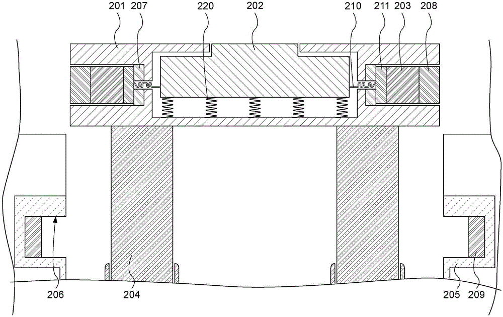
图3为根据本发明的实施例的处于延伸位置的可收缩手柄的横截面图,其中保持销定位在手柄内;3 is a cross-sectional view of a retractable handle in an extended position with a retention pin positioned within the handle in accordance with an embodiment of the present invention;
图4为根据本发明的实施例的处于收缩和锁定位置的可收缩手柄的横截面图,其中保持销安放在凹槽内;4 is a cross-sectional view of a retractable handle in a retracted and locked position with a retaining pin seated in a groove, in accordance with an embodiment of the present invention;
图5为根据本发明的实施例的处于收缩位置的可收缩手柄的横截面图,其中在致动期间保持销定位在手柄内;5 is a cross-sectional view of a retractable handle in a retracted position with a retention pin positioned within the handle during actuation in accordance with an embodiment of the present invention;
图6为根据另一实施例的处于收缩位置的可收缩手柄的横截面图,其中弹簧将保持销推动到凹槽中;6 is a cross-sectional view of a retractable handle in a retracted position according to another embodiment, wherein a spring pushes the retaining pin into the groove;
图7为具有额外保持销以将手柄锁定在延伸位置中的可收缩手柄的横截面图;Figure 7 is a cross-sectional view of a retractable handle with an additional retention pin to lock the handle in an extended position;
图8为根据本发明的实施例的具有固定在竖直位置中的开放嵌板的打开的箱子/手提箱的透视图,所述开放嵌板充当用于自组装可折叠或可附接或可以其它方式展开的水平物架的支撑结构;Figure 8 is a perspective view of an open box/suitcase with open panels fixed in a vertical position that act as collapsible or attachable or can be folded for self-assembly, according to an embodiment of the invention The supporting structure of the horizontal shelf deployed in other ways;
图9为根据本发明的实施例的具有固定在竖直位置中的开放嵌板的打开的手提箱的透视图,所述开放嵌板充当用于展开的自组装物架的支撑结构;9 is a perspective view of an open suitcase with open panels secured in a vertical position, the open panels serving as a support structure for a self-assembling shelf deployed, in accordance with an embodiment of the present invention;
图10为根据本发明的实施例的具有固定在竖直位置中的开放嵌板的打开的手提箱的透视图,所述开放嵌板充当用于折叠的水平物架的支撑结构;10 is a perspective view of an open suitcase with open panels secured in a vertical position, the open panels serving as a support structure for a folded horizontal shelf, according to an embodiment of the present invention;
图11为根据本发明的实施例的具有固定在竖直位置中的开放嵌板的打开的手提箱的透视图,所述开放嵌板充当用于展开的水平物架和限制构件的支撑结构。11 is a perspective view of an open suitcase with open panels secured in a vertical position, the open panels serving as support structures for the unfolded horizontal shelf and restraint members, according to an embodiment of the invention.
具体实施方式Detailed ways
所属领域中已知多种类型的具有可延伸手柄的滚动箱,包含全尺寸的手提箱、服装包、工具箱、电子箱和随身行李箱。在第4,759,431号、第5,253,739号、第5,575,362号和第5,639,521号美国专利中展示了具有用于推动或拉动行李箱的延伸手柄的滚动行李箱的实例,所述美国专利的公开内容以引用的方式并入本文中。还已知具有延伸和收缩手柄的其它滚动箱,包含电子箱、乐器箱、工具箱等。具有可延伸手柄的工具箱的实例描绘于第7,854,321号美国专利中,所述美国专利的公开内容以引用的方式并入本文中。Various types of rolling cases with extendable handles are known in the art, including full-sized suitcases, garment bags, tool cases, electronics cases, and carry-on luggage. Examples of rolling luggage with extended handles for pushing or pulling the luggage are shown in US Pat. incorporated into this article. Other rolling cases with extend and retract handles are also known, including electronic cases, instrument cases, tool cases, and the like. An example of a tool case with an extendable handle is depicted in US Patent No. 7,854,321, the disclosure of which is incorporated herein by reference.
本发明通过创建被配置成承受被拖曳、推动或承载的箱子的负载的可延伸且可收缩手柄来克服常规可延伸且可收缩手柄的缺点。本发明的手柄适合于在任何种类的箱子、行李箱、箱体或罩壳中使用,例如上文所描述的那些箱子但不限于此。The present invention overcomes the disadvantages of conventional extendable and retractable handles by creating an extendable and retractable handle configured to bear the load of a case being towed, pushed or carried. The handle of the present invention is suitable for use in any kind of case, luggage, case or case, such as but not limited to those described above.
图1描绘具有可延伸且可收缩手柄120的箱子100。在图1中,手柄处于收缩位置;其可经由臂125从手柄支座130延伸。如图1中所见,箱子100可任选地包含用于推进手提箱的滚轮140,但箱子100并不需要滚轮。图2描绘经由臂125处于延伸位置的手柄120。在一些实施例中,臂125可为使用同心管的可伸缩臂,所述同心管通常具有圆形、正方形或矩形横截面。FIG. 1 depicts a
图3描绘手柄结构200的横截面,其可将手柄201锁定到箱子的结构元件,使得手柄变为承载件,且整个箱子可由手柄提起而不损坏手柄或任何延伸臂/可伸缩臂。手柄包含致动器202,所述致动器如图3中所见可呈按钮的形式,所述按钮包含一个或多个弹簧220以用于使按钮返回初始非致动状态。两个可移动保持构件203定位在手柄内,且可为可从手柄传递到定位在手柄支座205或任何框架或支架内的凹槽206中的销、螺栓、紧固件或其它可移动保持元件,所述手柄支座或框架或支架与箱子的结构元件进行连接以用于将负载从手柄转移到箱子结构自身。手柄结构连接到可延伸且可收缩臂204,使得手柄201可在臂204上延伸或收缩。可延伸且可收缩臂204可包含伸缩构件,例如在彼此内伸缩以便缩短存储在附接有手柄的包、行李箱或箱子内的长度的圆柱形管或矩形管。Figure 3 depicts a cross-section of the
应注意,尽管展示两组元件(销、臂、凹槽、磁体等),但应理解,取决于手柄的所需强度、箱子的大小和待承载于箱子内的内容物的性质,可使用一组或多于两组元件。It should be noted that although two sets of elements (pins, arms, grooves, magnets, etc.) Group or more than two groups of elements.
图3描绘处于延伸位置的可延伸且可收缩手柄201。在延伸位置中,两个保持销203通过任何已知的保持或紧固构件,例如,磁体、钩环紧固件(例如,VELCRO)、螺钉等收缩在手柄201内。在图3的实例中,保持销包含一对磁体:销锁定磁体208,其用于与凹槽206中的凹槽锁定磁体209协作;以及销收缩磁体211,其用于与定位在手柄内的手柄收缩磁体207协作。在图3中,手柄收缩磁体207已以磁性方式吸引销收缩磁体211,使得销在手柄处于延伸位置时紧固地保持在手柄内。Figure 3 depicts the extendable and
当如图4中展示手柄201完全收缩时,保持销203与凹槽206对准。销锁定磁体208被吸到锁定磁体209。即,磁体208与209之间的吸力可比销收缩磁体211与手柄收缩磁体207之间的吸力强。基于此吸力,保持销203自动向外移动到凹槽206中,从而将手柄201牢固地锁定或接合到手柄支座205(或箱子的任何其它结构元件),从而阻止手柄的任何抽出移动。保持销203将承载力从手柄201传递到手柄支座205,所述手柄支座为箱子的结构部分或附接到箱子的结构部分。即,凹槽206和手柄支座205可为手提箱或箱体框架或将负载分布到将由手柄201提起的箱体的结构元件的任何其它结构的部分。When handle 201 is fully retracted as shown in FIG. 4 ,
因此,在操作中,销锁定磁体208与凹槽锁定磁体209之间的吸力被配置成比销收缩磁体211与手柄收缩磁体207之间的吸力强,使得保持销203被配置成自动移动到凹槽206中。此将手柄201与手柄支座205联合起来以阻止手柄的任何抽出移动且将承载力从手柄201转移到手柄支座205。Thus, in operation, the attractive force between the
为了延伸手柄201,用户将保持销203从凹槽206收缩到手柄201的内部中。如图5中所见,当按压致动器202时,其例如借助于缆线210或将保持销203拉向手柄保持磁体207的任何其它结构使保持销203缩回手柄201中。一旦保持销203收缩在手柄201内并且锁定到磁体207,用户就可以延伸手柄201/臂204,这是因为手柄201将清除凹槽206,从而允许整个组合件从手柄支座205自由移出。To extend
虽然在上述图中描绘两个销203,但应理解,可使用单个销或多于两个销。除销以外,还可使用其它锁定构件。举例来说,闩锁可与凹槽中的互锁构件一起使用,其中手柄中的致动器释放闩锁。手柄中的按钮致动器可连接到缆线以从凹陷部分中的连接释放闩锁元件。可使用常规可商购的闩锁。简单地说,用于将手柄锁定在适当位置的任何机构可用于实现本发明的目标。Although two
本发明的手柄可并入到上述专利中所描绘的行李箱和箱体中的任一个中,且还并入到使用可延伸手柄且被配置成承载件的任何其它装置中。以此方式,仅需要单个手柄用于滚动箱和用于承载箱子两者,从而消除了在承载应用中延伸手柄误用的问题。The handle of the present invention may be incorporated into any of the luggage and cases depicted in the aforementioned patents, and also into any other device that uses an extendable handle and is configured as a carrier. In this way, only a single handle is required for both the rolling case and for carrying the case, thereby eliminating the problem of misuse of extension handles in carrying applications.
转而参看图6,描绘本发明的另一方面。在图6中,弹簧用于致动保持销,其中收缩缆线用于抽出手柄内的保持销。当如图6中展示手柄301完全收缩时,保持销303与凹槽306对准。此处描绘为常开型弹簧330的一个或多个致动器将销303推入凹槽306中。基于弹簧力,保持销303自动向外移动到凹槽306中,从而将手柄301牢固地接合到手柄支座305(或箱子的任何其它结构元件),从而阻止手柄的任何抽出移动。保持销303将承载力从手柄301转移到手柄支座305,所述手柄支座为箱子的结构部分或附接到箱子的结构部分。即,凹槽306和手柄支座305可为手提箱或箱体框架或将负载分布到将由手柄201提起的箱体的结构元件的任何其它结构的部分。Referring now to Figure 6, another aspect of the present invention is depicted. In Figure 6, a spring is used to actuate the retaining pin, where a retraction cable is used to extract the retaining pin inside the handle. When the
为了缩回销303,如图6所示,克服弹簧320的力按压致动器302,且克服常开型弹簧330的弹簧力拉动缆线310或其它撤回元件,以关闭弹簧330并从凹槽306抽出销303。手柄301接着可沿着臂304延伸以沿着任选的滚轮拉动箱子。在弹簧330处于压缩关闭位置的情况下,闩锁元件(图中未展示)可将弹簧维持在关闭位置,使得当手柄处于延伸状态时,销303保持在手柄301内。To retract the
当需要将行李箱手柄锁定在延伸位置中时,上述图的销203或303可任选地位于除手柄之外的位置中。图7示意性地描绘了一个选项,其中提供了两组销403和440,使用户可以选择将手柄锁定在收缩位置或延伸位置。在完全锁定位置中,保持销403和440分别与凹槽406和446对准。应注意,任选地,不提供凹槽446,并且即使在图7的“手柄锁定”位置中,销440也收缩在臂404内。当需要向在收缩和锁定位置中的手柄结构提供额外强度时,仅提供凹槽446及其磁体407和411。销锁定磁体408被吸到锁定磁体409,其中任选的凹槽磁体459被吸到销磁体458。When it is desired to lock the luggage handle in the extended position, the
在操作中,当按压致动器402时,缆线410和460从相应的凹槽406和446中抽出销403和440。当手柄401完全延伸时,销440与上部凹槽406对准,并且磁体408对磁体409的吸力将销440吸到凹槽406中,从而将手柄锁定在延伸位置中。因此,用户可以在手柄处于延伸位置的情况下安全地提起箱子,而不必将手柄移动到收缩位置以便将负载从手柄分布到箱子结构元件。In operation, when
在另一方面,本发明提供一种用于例如手提箱的箱子的组织系统,其用于管理在到达目的地之后的个人物品以及提供最大打包灵活性。确切地说,本发明系统使用箱子/手提箱自身的至少一部分作为用于集成组织系统的支撑结构。此外,系统至少部分自组装;即,用于装纳衣服和其它个人物品的物架在用户的最小努力下自动地或半自动地从折叠状态重新定位到打开状态。系统可与上述承载手柄系统结合使用,或可独立于承载手柄系统而使用。In another aspect, the present invention provides an organization system for boxes, such as suitcases, for managing personal items upon arrival at a destination and providing maximum packing flexibility. Rather, the system of the present invention uses at least a portion of the case/suitcase itself as a support structure for the integrated organizational system. Furthermore, the system is at least partially self-assembling; that is, the racks for holding clothes and other personal items are automatically or semi-automatically repositioned from a folded state to an open state with minimal user effort. The system may be used in conjunction with the carrying handle system described above, or may be used independently of the carrying handle system.
图8描绘手提箱510,其具有存储部分530和罩盖部分515。罩盖部分515通常通过拉链、搭扣或钩环紧固件(例如,VELCRO)或其组合附接到存储部分530。罩盖部分515和/或存储部分530可包含在图式中不可见的框架构件,以维持手提箱的刚度和结构完整性。举例来说,刚性金属或塑料框架可具有织物罩盖以产生轻量手提箱。替代地,罩盖515和存储部分530可为由例如聚碳酸酯或丙烯腈丁二烯苯乙烯(ABS)或其组合的刚性塑料材料制成的硬壳行李箱元件。FIG. 8 depicts a
固定到手提箱510的罩盖部分515的一个或多个物架520在图8中显示为处于打开、已组装位置。物架可为刚性或可压缩的;在一个实施例中,物架可包含具有覆盖框架的织物的金属或塑料线材框架。刚性塑料板可包含于物架的底部部分中。织物或弹性体铰链可以将物架连接到手提箱10的罩盖部分515。替代地,物架可从罩盖部分515移除且包含附接构件,例如拉链、钩环紧固件、搭扣或其它已知附接件。The one or
任选的关闭构件525(例如,钩环紧固件,例如VELCRO)可将物架520维持在关闭位置。替代地,当手提箱的罩盖打开时,物架可以自动打开。在任一实施例中,用户无需配置物架,因为物架可通过打开罩盖部分515或解锁关闭构件525的动作而自组装到打开位置。通过使用关闭构件525,当不需要物架520时,其可被存储而不占用任何空间;替代地,为了不限制用户打包行李的方式,可将其移除。An optional closure member 525 (eg, a hook and loop fastener, such as VELCRO) can maintain the
为了将具有附接到其的物架的手提箱的部分维持在打开位置中,可以任选地使用一个或多个手提箱滚轮作为锚固件来提供锁定机构。举例来说,底部可包含摩擦配合收纳元件,其锁定到滚轮中以将手提箱的罩盖部分固定在打开位置中。To maintain the portion of the suitcase with the shelf attached thereto in the open position, a locking mechanism may optionally be provided using one or more suitcase rollers as anchors. For example, the bottom may include friction fit receiving elements that lock into the rollers to secure the lid portion of the suitcase in the open position.
在图8的实施例中,罩盖构件515的刚度足以支撑物架520和置于其上的任何衣服的重量。尽管物架520描绘为具有边缘部分,但应理解,其可完全打开(例如,平板)或可为任选地包含拉上的封闭件(或其它紧固件,例如搭扣、钩环或按钮)的封闭袋。以此方式,可提供封闭的物架以容纳脏衣服。物架520可使用罩盖构件515的整个区域或罩盖构件515的较小区域。In the embodiment of FIG. 8, the
图10描绘可折叠到相对平坦的配置的替代性物架620。物架620可任选地通过例如上文所描述的那些紧固件维持在折叠位置中。如果物品未放在物架内,则处于折叠位置的物架可在手提箱600内几乎不占空间。在图9中,物架620已被释放以展开/自组装,或替代地,已通过打开罩盖部分615的动作展开。物架可具有由织物、网状物或塑料薄片覆盖的柔性或刚性金属或塑料框架。任选地,可提供刚性增强底板。FIG. 10 depicts an
在图11中描绘了组织系统的另一实施例。在图11中,箱子/手提箱600包含罩盖部分615、存储部分630和限制构件650。限制构件以可移除方式附接在罩盖部分615与存储部分630之间,以限制罩盖部分的打开。限制构件可为织物、幅板材料、弹性体或部分弹性体。在一些实施例中,限制构件可被选择为刚性构件,例如刚性塑料或金属棒。以此方式,将罩盖部分615维持在大致竖直位置以成为物架的竖直支撑构件。Another embodiment of an organizing system is depicted in FIG. 11 . In FIG. 11 , case/
取决于物架的大小和配置,物架可被用作用于在手提箱的封装期间装纳衣服或浴室用品的隔室。在此类实施例中,通过紧固件提供封闭件。一旦释放紧固件之后,衣服就被预布置在物架620上,从而消除了用户打开箱子/手提箱的需要。Depending on the size and configuration of the rack, the rack may be used as a compartment for storing clothes or bathroom items during packaging of the suitcase. In such embodiments, the closure is provided by fasteners. Once the fasteners are released, the garment is pre-arranged on the
应对所属领域的技术人员显而易见的是,在不脱离本文的发明概念的情况下,除了已经描述的那些修改之外,许多修改也是可能的。因此,除了本公开的精神之外,本发明的主题不受限制。此外,在解释本公开时,应以与上下文一致的尽可能广泛的方式解释所有术语。确切地说,术语“包含(includes/including)”、“包括(comprises/comprising)”应解释为以非排它性方式指代元件、组件或步骤,指示所引用的元件、组件或步骤可存在或被利用,或与未明确地引用的其它元件、组件或步骤组合。It should be apparent to those skilled in the art that many modifications other than those already described are possible without departing from the inventive concepts herein. Accordingly, the inventive subject matter is not to be limited except in the spirit of the disclosure. Furthermore, in interpreting the present disclosure, all terms should be interpreted in the broadest possible manner consistent with the context. Rather, the terms "includes/including", "comprises/comprising" should be interpreted as referring to elements, components or steps in a non-exclusive manner, indicating that the referenced elements, components or steps may be present or utilized, or combined with other elements, components or steps not explicitly cited.
Claims (15)
Applications Claiming Priority (5)
| Application Number | Priority Date | Filing Date | Title |
|---|---|---|---|
| US202062989880P | 2020-03-15 | 2020-03-15 | |
| US62/989,880 | 2020-03-15 | ||
| US202062990421P | 2020-03-16 | 2020-03-16 | |
| US62/990,421 | 2020-03-16 | ||
| PCT/CN2021/080733 WO2021185199A1 (en) | 2020-03-15 | 2021-03-15 | Retractable and extendable loadbearing handle and luggage system |
Publications (2)
| Publication Number | Publication Date |
|---|---|
| CN114025637A CN114025637A (en) | 2022-02-08 |
| CN114025637B true CN114025637B (en) | 2023-03-28 |
Family
ID=77768039
Family Applications (1)
| Application Number | Title | Priority Date | Filing Date |
|---|---|---|---|
| CN202180003225.0A Active CN114025637B (en) | 2020-03-15 | 2021-03-15 | Retractable and extendable carrying handle and luggage system |
Country Status (4)
| Country | Link |
|---|---|
| US (1) | US11744341B2 (en) |
| EP (1) | EP4120872B1 (en) |
| CN (1) | CN114025637B (en) |
| WO (1) | WO2021185199A1 (en) |
Families Citing this family (2)
| Publication number | Priority date | Publication date | Assignee | Title |
|---|---|---|---|---|
| US11622608B2 (en) * | 2021-03-29 | 2023-04-11 | Alan Samuelson | Luggage handle |
| CN220898149U (en) * | 2023-09-22 | 2024-05-07 | 温州佳鸿锁具科技有限公司 | Hidden spring handle and case and bag that contains this handle |
Citations (5)
| Publication number | Priority date | Publication date | Assignee | Title |
|---|---|---|---|---|
| US6047442A (en) * | 1998-03-03 | 2000-04-11 | Tumi, Inc. | Releasable lock mechanism for luggage towing handle |
| US6357566B1 (en) * | 2000-06-06 | 2002-03-19 | Porter Case, Inc. | Carry-on case |
| CN206534263U (en) * | 2017-01-06 | 2017-10-03 | 浙江辰珂西传动机械有限公司 | A kind of structure improved case drawbar |
| CN206659365U (en) * | 2017-03-14 | 2017-11-24 | 郑男 | A kind of anti-aging case drawbar |
| CN109497672A (en) * | 2019-01-10 | 2019-03-22 | 上海途加箱包商贸有限公司 | Trolley case |
Family Cites Families (20)
| Publication number | Priority date | Publication date | Assignee | Title |
|---|---|---|---|---|
| US923807A (en) * | 1907-06-28 | 1909-06-08 | Seymour W Bonsall | Trunk. |
| US3869034A (en) * | 1973-01-29 | 1975-03-04 | Jr Henry M Thornton | Wardrobe apparel case |
| US4759431A (en) | 1987-04-15 | 1988-07-26 | Samsonite Corporation | Travel bag with combination pull handle and auxiliary bag strap |
| US5253739A (en) | 1992-03-19 | 1993-10-19 | Samsonite Corporation | Wheeled flight bag with retractable pull handle |
| US5575362A (en) | 1995-01-05 | 1996-11-19 | Samsonite Corporation | Collapsible pull handle for wheeled garment bag |
| US5639521A (en) | 1996-01-26 | 1997-06-17 | Fraus; Joan K. | Ornamental christmas display |
| US5924169A (en) * | 1997-10-09 | 1999-07-20 | Ting Cheng Co., Ltd. | Suitcase handle device |
| US6079527A (en) * | 1998-10-01 | 2000-06-27 | Chaw-Khong Technology Co., Ltd. | Retractable handle for wheeled luggage |
| US7097181B2 (en) * | 2001-11-02 | 2006-08-29 | Outrigger, Inc. | Angular handle assembly for wheeled luggage |
| US20050126872A1 (en) | 2003-12-10 | 2005-06-16 | Yoav Dror | Convertible luggage |
| ITMI20050175U1 (en) * | 2005-05-13 | 2006-11-14 | Valextra Srl | WORK BAG OR TRAVEL BAGGAGE WITH EXTENDABLE BUILT-IN HANDLE WITH WHEELS |
| US7658269B2 (en) * | 2006-02-13 | 2010-02-09 | Chen-Chuan Wu | Handle of a two pulling rod suitcase |
| US7779976B2 (en) * | 2006-09-08 | 2010-08-24 | Ingenious Designs Llc | Versatile and reconfigurable luggage |
| US7854321B2 (en) | 2008-07-01 | 2010-12-21 | The Stanley Works Israel Ltd. | Rolling container assembly |
| US20100276241A1 (en) | 2009-05-04 | 2010-11-04 | Malone Richard C | Hanging shelf system and travel organizer for use in combination with a suitcase |
| US9113687B2 (en) * | 2012-02-28 | 2015-08-25 | Brian Christopher Guidry | Magnetic locking device system and method |
| US8474098B1 (en) * | 2012-05-28 | 2013-07-02 | Great Taiwan Material Handling Co. | Adjustable pulling rod set |
| US9408449B1 (en) | 2015-01-15 | 2016-08-09 | Hokei Corporation | Stepless retractable handle assembly for luggage |
| JP2018134531A (en) * | 2018-06-07 | 2018-08-30 | 株式会社ティーアンドエス | suitcase |
| CN209950585U (en) * | 2019-05-16 | 2020-01-17 | 嘉兴市弘朗箱包配件有限公司 | Luggage pull rod with underneath control button |
-
2021
- 2021-03-15 CN CN202180003225.0A patent/CN114025637B/en active Active
- 2021-03-15 EP EP21772499.6A patent/EP4120872B1/en active Active
- 2021-03-15 WO PCT/CN2021/080733 patent/WO2021185199A1/en not_active Ceased
- 2021-03-15 US US17/614,546 patent/US11744341B2/en active Active
Patent Citations (5)
| Publication number | Priority date | Publication date | Assignee | Title |
|---|---|---|---|---|
| US6047442A (en) * | 1998-03-03 | 2000-04-11 | Tumi, Inc. | Releasable lock mechanism for luggage towing handle |
| US6357566B1 (en) * | 2000-06-06 | 2002-03-19 | Porter Case, Inc. | Carry-on case |
| CN206534263U (en) * | 2017-01-06 | 2017-10-03 | 浙江辰珂西传动机械有限公司 | A kind of structure improved case drawbar |
| CN206659365U (en) * | 2017-03-14 | 2017-11-24 | 郑男 | A kind of anti-aging case drawbar |
| CN109497672A (en) * | 2019-01-10 | 2019-03-22 | 上海途加箱包商贸有限公司 | Trolley case |
Also Published As
| Publication number | Publication date |
|---|---|
| CN114025637A (en) | 2022-02-08 |
| US11744341B2 (en) | 2023-09-05 |
| WO2021185199A1 (en) | 2021-09-23 |
| EP4120872A4 (en) | 2024-03-27 |
| EP4120872B1 (en) | 2025-01-01 |
| US20220240639A1 (en) | 2022-08-04 |
| EP4120872A1 (en) | 2023-01-25 |
Similar Documents
| Publication | Publication Date | Title |
|---|---|---|
| US7607535B2 (en) | Clothes container with an extendable clothes hanging system | |
| EP0132016B1 (en) | Wheeled garment bag | |
| EP2651258B1 (en) | Improved articles of luggage | |
| US9084460B2 (en) | Portable device for storing and retrieving items of apparel | |
| CN114025637B (en) | Retractable and extendable carrying handle and luggage system | |
| US10238195B2 (en) | Luggage apparatus | |
| US20100276241A1 (en) | Hanging shelf system and travel organizer for use in combination with a suitcase | |
| US20140027227A1 (en) | Carry-on bag with pull-out coat hangers in handle top | |
| US8607946B2 (en) | Convertible luggage bag | |
| CN104337165B (en) | A kind of handle arrangement for luggage case and the luggage case for including the handle arrangement | |
| US8820498B2 (en) | Expandable suitcase | |
| JP5940142B2 (en) | Hanging access structure for laptop | |
| WO2005055759A2 (en) | Convertible luggage | |
| WO2022059003A1 (en) | An expandable bag and an apparatus for expanding a bag | |
| EP0940099A2 (en) | Article of luggage having divider for opposing sections | |
| US10492582B2 (en) | Multifunction convertible suitcase system | |
| US20160213111A1 (en) | Collapsible case | |
| JP3181838U (en) | Suitcase base and suitcase using the same | |
| US20130192498A1 (en) | Compact lap desk | |
| US20200170367A1 (en) | Garment hanger mechanism and system for travel bags and luggage | |
| CN216776335U (en) | Luggage with adjustable storage space | |
| CN222264610U (en) | Luggage system | |
| KR20220001957U (en) | Functional bag with repositionable partition | |
| US20250386912A1 (en) | Luggage system | |
| JP3091160U (en) | Carry Bag |
Legal Events
| Date | Code | Title | Description |
|---|---|---|---|
| PB01 | Publication | ||
| PB01 | Publication | ||
| SE01 | Entry into force of request for substantive examination | ||
| SE01 | Entry into force of request for substantive examination | ||
| GR01 | Patent grant | ||
| GR01 | Patent grant |