Disclosure of Invention
The present invention is directed to a closed micro gas turbine cycle system with peak load rejection and method of operating the same that solves one or more of the problems set forth above. The gas turbine circulating system can improve fuel adaptability and realize comprehensive utilization of energy and peak shaving energy storage functions.
In order to achieve the purpose, the invention adopts the following technical scheme:
the invention relates to a closed micro gas turbine circulating system capable of adjusting peak energy storage, which comprises: the system comprises a gas compressor, a first heat exchanger, a first heat storage tank, a second heat exchanger, a second heat storage tank, a gas storage tank, a third heat exchanger, a turbine and a combustor;
a first outlet of the compressor is communicated with a first inlet of the first heat exchanger, and a second outlet of the compressor is communicated with a first inlet of the second heat exchanger; a first outlet of the first heat exchanger is communicated with an inlet of the gas storage tank; an outlet of the gas storage tank and a first outlet of the second heat exchanger are communicated with a first inlet of the third heat exchanger through a first communicating pipeline; the first outlet of the third heat exchanger is communicated with the inlet of the turbine; the turbine is used for driving the generator to generate electricity; the outlet of the turbine is communicated with the inlet of the compressor;
an inlet of the first heat storage tank is communicated with a second outlet of the first heat exchanger, and an outlet of the first heat storage tank is communicated with a second inlet of the first heat exchanger; an inlet of the second heat storage tank is communicated with a second outlet of the second heat exchanger, and an outlet of the second heat storage tank is communicated with a second inlet of the second heat exchanger;
and the inlet of the combustor is used for introducing fuel and air, and the outlet of the combustor is communicated with the second inlet of the third heat exchanger.
The invention is further improved in that the outlet of the gas storage tank and the first outlet of the second heat exchanger are also communicated with the first inlet of the third heat exchanger through a second communication pipeline; and a first control valve is arranged on the first communicating pipeline, and a second control valve is arranged on the second communicating pipeline.
The invention further improves the method and also comprises the following steps: the first preheating heat exchanger module is used for preheating air introduced into the combustor through the exhaust of the turbine, inputting the preheated air into the combustor and inputting the heat-exchanged exhaust into the compressor; and the second preheating heat exchanger module is used for preheating the exhaust of the turbine and then inputting the exhaust into the compressor.
A further refinement of the invention is that the first preheat heat exchanger module comprises: a fourth heat exchanger and a fifth heat exchanger;
an outlet of the turbine is sequentially communicated with a heat flow channel of the fourth heat exchanger, a heat flow channel of the fifth heat exchanger and an inlet of the compressor through a third communicating pipeline;
and the cold flow channel of the fifth heat exchanger is communicated with the air inlet of the combustor through the cold flow channel of the fourth heat exchanger.
A further refinement of the invention is that the second preheat heat exchanger module includes: a sixth heat exchanger and a seventh heat exchanger;
an outlet of the turbine is sequentially communicated with a cold flow channel of the sixth heat exchanger, a cold flow channel of the seventh heat exchanger and an inlet of the compressor through a fourth communicating pipeline;
and the third communicating pipeline is provided with a third control valve, and the fourth communicating pipeline is provided with a fourth control valve.
The invention further improves the method and also comprises the following steps: an eighth heat exchanger;
and an inlet of the compressor is respectively communicated with a cold flow channel of the seventh heat exchanger and a hot flow channel of the fifth heat exchanger through the eighth heat exchanger.
The invention further improves the method and also comprises the following steps: and the generator is used for generating electricity under the driving of the turbine.
The invention relates to an operation method of a closed micro gas turbine circulating system capable of adjusting peak energy storage, which comprises the following steps:
(1) when the external fuel is used for heating the working medium:
when a user is in a power consumption valley, a normal-pressure working medium enters the gas compressor for pressurization, a part of the pressurized working medium enters the first heat exchanger, heat is stored in the first heat storage tank, and the cooled working medium enters the gas storage tank for storage; the other part of the pressurized working medium enters a second heat exchanger, heat is stored in a second heat storage tank, the cooled working medium enters a third heat exchanger to exchange heat with gas from a combustor, and the heated working medium enters a turbine to expand and do work for driving a generator to generate electricity; the working medium discharged from the outlet of the turbine is used as a heat source of an external system;
when a user is in a peak of power consumption, a normal-pressure working medium enters the gas compressor to be pressurized, the pressurized working medium is completely discharged into the second heat exchanger, heat is stored in the second heat storage tank, the cooled working medium enters the third heat exchanger to exchange heat with fuel gas from the combustor, and the working medium stored in the gas storage tank is discharged into the third heat exchanger to exchange heat; the heated working medium enters a turbine to expand and do work and is used for driving a generator to generate electricity; the working medium discharged from the outlet of the turbine is used as a heat source of an external system;
(2) when the working medium is not heated by using external fuel:
when a user is in a power consumption valley, a normal-pressure working medium enters the gas compressor for pressurization, a part of the pressurized working medium enters the first heat exchanger, heat is stored in the first heat storage tank, and the cooled working medium enters the gas storage tank for storage; the other part of the pressurized working medium enters a second heat exchanger, heat is stored in a second heat storage tank, the cooled working medium enters a third heat exchanger to exchange heat with gas from a combustor, and the heated working medium enters a turbine to expand and do work for driving a generator to generate electricity; the working medium discharged from the outlet of the turbine is used as a cold source of an external system;
when a user is in a peak of power consumption, a normal-pressure working medium enters the gas compressor to be pressurized, the pressurized working medium is completely discharged into the second heat exchanger, heat is stored in the second heat storage tank, the cooled working medium enters the third heat exchanger to exchange heat with fuel gas from the combustor, and the working medium stored in the gas storage tank is discharged into the third heat exchanger to exchange heat; the heated working medium enters a turbine to expand and do work and is used for driving a generator to generate electricity; and the working medium discharged from the outlet of the turbine is used as a cold source of an external system.
When external fuel is used for heating the working medium, the pressure ratio of a gas compressor is 2-6, and the temperature of a turbine inlet is 600-1000 ℃; when the working medium is not heated by using external fuel, the pressure ratio of the compressor is 2-6, and the temperature of the turbine inlet is 25-30 ℃.
Compared with the prior art, the invention has the following beneficial effects:
the closed micro gas turbine circulating system capable of adjusting peak energy storage provided by the invention can improve fuel adaptability and realize comprehensive utilization of energy and peak energy storage functions. Specifically, the closed gas turbine is adopted for circulation, fuel combustion is separated from working medium heat exchange, high-temperature gas generated after the fuel is combusted in the combustor enters the heat exchanger to heat the working medium, and therefore the requirement on the cleanliness of the fuel is reduced, the selection of the fuel is diversified, and the adaptability of the fuel is improved. According to the invention, by utilizing the air storage tank, part of high-pressure air is stored in the low ebb of electricity utilization, and the stored high-pressure air is used for increasing the system output in the peak of electricity utilization, so that the peak-shaving energy storage function is realized.
The invention can provide cold for external system and realize comprehensive utilization of energy by coupling refrigeration cycle and using refrigeration cycle when fuel is not used to heat working medium.
Detailed Description
In order to make the technical solutions of the present invention better understood, the technical solutions in the embodiments of the present invention will be clearly and completely described below with reference to the drawings in the embodiments of the present invention, and it is obvious that the described embodiments are only a part of the embodiments of the present invention, and not all of the embodiments. All other embodiments, which can be derived by a person skilled in the art from the embodiments given herein without making any creative effort, shall fall within the protection scope of the present invention.
It should be noted that the terms "first," "second," and the like in the description and claims of the present invention and in the drawings described above are used for distinguishing between similar elements and not necessarily for describing a particular sequential or chronological order. It is to be understood that the data so used is interchangeable under appropriate circumstances such that the embodiments of the invention described herein are capable of operation in sequences other than those illustrated or described herein. Furthermore, the terms "comprises," "comprising," and "having," and any variations thereof, are intended to cover a non-exclusive inclusion, such that a process, method, system, article, or apparatus that comprises a list of steps or elements is not necessarily limited to those steps or elements expressly listed, but may include other steps or elements not expressly listed or inherent to such process, method, article, or apparatus.
The invention is described in further detail below with reference to the accompanying drawings:
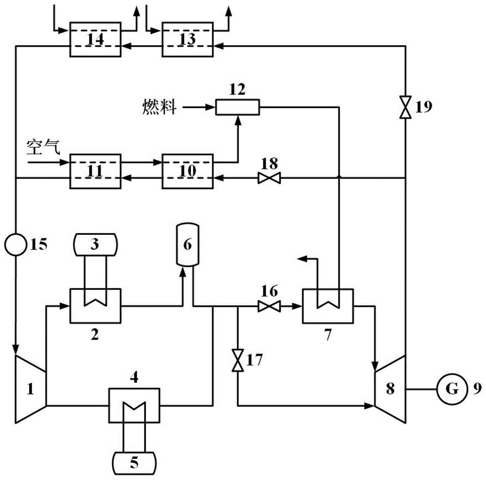
referring to fig. 1, a closed micro gas turbine cycle system with peak-load adjustable function according to an embodiment of the present invention includes: the heat recovery system comprises a compressor 1, a first heat exchanger 2, a first heat storage tank 3, a second heat exchanger 4, a second heat storage tank 5, a gas storage tank 6, a third heat exchanger 7, a turbine 8, a generator 9, a fourth heat exchanger 10, a fifth heat exchanger 11, a combustor 12, a sixth heat exchanger 13, a seventh heat exchanger 14, an eighth heat exchanger 15, a first control valve 16, a second control valve 17, a third control valve 18 and a fourth control valve 19.
Specifically, the closed micro gas turbine circulating system capable of adjusting peak energy storage in the embodiment of the invention comprises a closed gas turbine circulating subsystem, an energy storage subsystem, a refrigeration circulating subsystem and a combustion heating subsystem.
In the embodiment of the invention, the closed gas turbine circulation subsystem is composed of a compressor 1, a second heat exchanger 4, a second heat storage tank 5, a third heat exchanger 7, a turbine 8, a generator 9, a fourth heat exchanger 10, a fifth heat exchanger 11, an eighth heat exchanger 15, a first control valve 16 and a third control valve 18. Wherein a first outlet of the compressor 1 is connected to a first inlet of a second heat exchanger 4 (illustratively, a first inlet of the second heat exchanger is communicated with a first outlet and is a heat flow passage), a second inlet of the second heat exchanger 4 (illustratively, a second inlet of the second heat exchanger is communicated with a second outlet and is a cold flow passage) is connected to an outlet of the second heat storage tank 5, a second outlet of the second heat exchanger 4 is connected to an inlet of the second heat storage tank 5, a first outlet of the second heat exchanger 4 is connected to an inlet of a first control valve 16, an outlet of the first control valve 16 is connected to a first inlet of a third heat exchanger 7, a first outlet of the third heat exchanger 7 (illustratively, a first inlet of the third heat exchanger is communicated with the first outlet, a second inlet is communicated with the second outlet) is connected to an inlet of a turbine 8, a main shaft of the turbine 8 is connected to a generator 9, to drive it to generate electricity, the outlet of the turbine 8 is connected to the inlet of a third control valve 18, the outlet of the third control valve 18 is connected to the first inlet of a fourth heat exchanger 10 (illustratively, the first inlet of the fourth heat exchanger is communicated with the first outlet, the second inlet is communicated with the second outlet), the first outlet of the fourth heat exchanger 10 is connected to the first inlet of a fifth heat exchanger 11 (illustratively, the first inlet of the fifth heat exchanger is communicated with the first outlet, the second inlet is communicated with the second outlet), the first outlet of the fifth heat exchanger 11 is connected to the inlet of an eighth heat exchanger 15, and the outlet of the eighth heat exchanger 15 is connected to the inlet of the compressor 1.
The heat stored in the second heat storage tank 5 in the embodiment of the invention can be used for supplying heat to external users, so that the diversity of system heat utilization is improved.
In the embodiment of the invention, the energy storage subsystem is composed of a gas compressor 1, a first heat exchanger 2, a first heat storage tank 3 and a gas storage tank 6. Wherein, the second outlet of the compressor 1 is connected with the first inlet of the first heat exchanger 2 (illustratively, the first inlet of the first heat exchanger is communicated with the first outlet, and the second inlet is communicated with the second outlet), the second inlet of the first heat exchanger 2 is connected with the outlet of the first heat storage tank 3, the second outlet of the first heat exchanger 2 is connected with the inlet of the heat storage tank 3, and the first outlet of the first heat exchanger 2 is connected with the inlet of the gas storage tank 6.
The heat stored in the first heat storage tank 3 in the embodiment of the invention can be used for supplying heat to external users, so that the heat utilization diversity of the system is improved.
In the embodiment of the invention, the refrigeration cycle subsystem is composed of a compressor 1, a second heat exchanger 4, a second heat storage tank 5, a turbine 8, a generator 9, a sixth heat exchanger 13, a seventh heat exchanger 14, an eighth heat exchanger 15, a second control valve 17 and a fourth control valve 19. A first outlet of the compressor 1 is connected with a first inlet of a second heat exchanger 4, a second inlet of the second heat exchanger 4 is connected with an outlet of a second heat storage tank 5, a second outlet of the second heat exchanger 4 is connected with an inlet of the second heat storage tank 5, a first outlet of the second heat exchanger 4 is connected with an inlet of a second control valve 17, an outlet of the second control valve 17 is connected with an inlet of a turbine 8, a main shaft of the turbine 8 is connected with a generator 9 to drive the turbine 8 to generate electricity, an outlet of the turbine 8 is connected with an inlet of a fourth control valve 19, an outlet of the fourth control valve 19 is connected with a first inlet of a sixth heat exchanger 13, a first outlet of the sixth heat exchanger 13 is connected with a first inlet of a seventh heat exchanger 14, a first outlet of the seventh heat exchanger 14 is connected with an inlet of an eighth heat exchanger 15, and an outlet of the eighth heat exchanger 15 is connected with an inlet of the compressor 1. Illustratively, the first inlet of all the heat exchangers is communicated with the first outlet, and the second inlet is communicated with the second outlet.
In the embodiment of the invention, the combustion subsystem is composed of a fourth heat exchanger 10, a fifth heat exchanger 11, a combustor 12 and a third heat exchanger 7. A second inlet of the fifth heat exchanger 11 is connected with the atmosphere, a second outlet of the fifth heat exchanger 11 is connected with a second inlet of the fourth heat exchanger 10, a second outlet of the fourth heat exchanger 10 is connected with a first inlet of the combustor 12, a second inlet of the combustor 12 is connected with the outside, and an outlet of the combustor 12 is connected with a second inlet of the second heat exchanger 7.
The closed micro gas turbine circulating system capable of adjusting peak energy storage provided by the embodiment of the invention can improve fuel adaptability and realize comprehensive utilization of energy and peak energy storage functions. Specifically, the closed gas turbine is adopted for circulation, fuel combustion is separated from working medium heat exchange, high-temperature gas generated after the fuel is combusted in the combustor enters the heat exchanger to heat the working medium, and therefore the requirement on the cleanliness of the fuel is reduced, the selection of the fuel is diversified, and the adaptability of the fuel is improved; the invention uses the refrigeration cycle when the fuel is not used to heat the working medium by coupling the refrigeration cycle, thereby providing cold energy for an external system and realizing the comprehensive utilization of energy; according to the invention, by utilizing the air storage tank, part of high-pressure air is stored in the low ebb of electricity utilization, and the stored high-pressure air is used for increasing the system output in the peak of electricity utilization, so that the peak-shaving energy storage function is realized.
The working process of the closed micro gas turbine circulating system with the adjustable peak energy storage comprises the following steps:
in the initial state, all control valves are in a closed state.
When the system is heating the working fluid with ambient fuel, the first control valve 16 and the third control valve 18 are opened.
When a user is in a power consumption valley, normal-pressure working medium discharged by the eighth heat exchanger 15 enters the gas compressor 1 to be pressurized, part of the pressurized working medium enters the first heat exchanger 2, part of heat is stored in the first heat storage tank 3, the cooled working medium enters the gas storage tank 6 to be stored, part of the cooled working medium enters the second heat exchanger 4, part of the heat is stored in the second heat storage tank 4, the cooled working medium enters the third heat exchanger 7 to exchange heat with high-temperature gas from the combustor 12, the heated working medium enters the turbine 8 to be expanded to do work, and a main shaft of the turbine 8 is connected with the generator 9 to drive the generator to generate power. Working media at the outlet of the turbine 8 sequentially pass through the fourth heat exchanger 10 and the fifth heat exchanger 11 for heat exchange, the part of heat is used for preheating air supplied for fuel combustion, the air is heated and then enters the combustor 12 to be mixed with the fuel for combustion, high-temperature gas after combustion and temperature rise enters the third heat exchanger 7 to serve as a heat source, the working media cooled by the fourth heat exchanger 10 and the fifth heat exchanger 11 enter the eighth heat exchanger 15 for further cooling, and then enter the gas compressor 1 to finish the circulation and energy storage process of the closed gas turbine.
When a user is in a peak of power utilization, the normal-pressure working medium discharged by the eighth heat exchanger 15 enters the gas compressor 1 to be pressurized, the pressurized working medium is completely discharged into the second heat exchanger 4, part of heat is stored in the second heat storage tank 4, and the cooled working medium enters the third heat exchanger 7 to exchange heat with high-temperature fuel gas from the combustor 12. Meanwhile, the working medium stored in the gas storage tank 6 is also discharged into the third heat exchanger 7 for heat exchange. The two parts of the heated working medium enter a turbine 8 to do work through expansion, a main shaft of the turbine 8 is connected with a generator 9 to drive the generator to generate electricity, and therefore the flow of the working medium is increased, the output of the system is increased, and the functions of peak clipping and valley filling are achieved. Working media at the outlet of the turbine 8 sequentially pass through the fourth heat exchanger 10 and the fifth heat exchanger 11 for heat exchange, the part of heat is used for preheating air supplied for fuel combustion, the air is heated and then enters the combustor 12 to be mixed with the fuel for combustion, high-temperature gas after combustion and temperature rise enters the third heat exchanger 7 to serve as a heat source, the working media cooled by the fourth heat exchanger 10 and the fifth heat exchanger 11 enter the eighth heat exchanger 15 for further cooling, and then enter the gas compressor 1, and the circulation and energy release processes of the closed gas turbine are completed.
When the system does not use external fuel to heat the working medium, the first control valve 16 and the third control valve 18 are closed, and the second control valve 17 and the fourth control valve 19 are opened.
When a user is in a power consumption valley, a normal-pressure working medium discharged by the eighth heat exchanger 15 enters the gas compressor 1 to be pressurized, part of the pressurized working medium enters the first heat exchanger 2, part of heat is stored in the first heat storage tank 3, the cooled working medium enters the gas storage tank 6 to be stored, part of the cooled working medium enters the second heat exchanger 4, part of the heat is stored in the second heat storage tank 4, the cooled working medium enters the turbine 8 to be expanded to do work, and a main shaft of the turbine 8 is connected with the generator 9 to drive the generator to generate power. Working media at the outlet of the turbine 8 sequentially pass through the sixth heat exchanger 13 and the seventh heat exchanger 14 to exchange heat and serve as cold sources of external systems, the heated working media enter the eighth heat exchanger 15 to be further heated and then enter the gas compressor 1, and the refrigeration cycle and energy storage process is completed.
When a user is in a peak of power utilization, normal-pressure working medium discharged by the eighth heat exchanger 15 enters the gas compressor 1 to be pressurized, the pressurized working medium is completely discharged into the second heat exchanger 4, part of heat is stored in the second heat storage tank 4, the cooled working medium enters the turbine 8 together with the working medium stored in the gas storage tank 6 to be expanded and do work, a main shaft of the turbine 8 is connected with the generator 9 to drive the generator to generate power, the flow of the working medium is increased, the output of the system is increased, and the functions of peak clipping and valley filling are achieved. The working medium at the outlet of the turbine 8 sequentially passes through the sixth heat exchanger 13 and the seventh heat exchanger 14 to exchange heat and serve as a cold source of an external system, the heated working medium enters the eighth heat exchanger 15 to be further heated and then enters the gas compressor 1, and the refrigeration cycle and energy release process is completed.
The embodiment of the invention is optional, the amount of air entering the air storage tank 6 during the energy storage process is determined according to the load of the power grid, when the load of the power grid is reduced, the amount of stored air can be correspondingly improved, and when the load of the power grid is improved, the amount of stored air can be correspondingly reduced.
The embodiment of the invention is optional, the number and the temperature range of the heat exchangers at the turbine outlet in the refrigeration cycle process can be selected according to the requirements of users, and the optimization of cold utilization is realized.
The embodiment of the invention preferably adopts the micro gas turbine for circulation, the stored pressure and temperature grade are low, the cost of equipment such as an air storage tank is reduced, and the system economy is improved.
According to the embodiment of the invention, the air storage tanks with different grades can be selected and matched according to different application scenes, so that the energy storage requirement is met, and the flexibility of the system is improved.
In the present invention, in view of economy, when closed gas turbine cycles are used, the main cycle parameters of the system may take the following values: the pressure ratio of the compressor is 2-6, the temperature of a turbine inlet is 600-1000 ℃, and the energy storage efficiency of the system is about 30-45% under a given parameter range;
in the present invention, in view of economy, when a refrigeration cycle is employed, the main cycle parameters of the system may take the following values: the pressure ratio of the compressor is 2-6, the temperature of a turbine inlet is about 25-30 ℃, and the energy storage efficiency of the system is about 50-60% under a given parameter range.
In summary, the invention provides a closed micro gas turbine circulation system and method capable of adjusting peak energy storage, which can improve fuel adaptability and realize comprehensive utilization of energy and peak energy storage functions. Specifically, the closed gas turbine is adopted for circulation, fuel combustion is separated from working medium heat exchange, high-temperature gas generated after the fuel is combusted in the combustor enters the heat exchanger to heat the working medium, and therefore the requirement on the cleanliness of the fuel is reduced, the selection of the fuel is diversified, and the adaptability of the fuel is improved; the invention uses the refrigeration cycle when the fuel is not used to heat the working medium by coupling the refrigeration cycle, thereby providing cold energy for an external system and realizing the comprehensive utilization of energy; according to the invention, by utilizing the air storage tank, part of high-pressure air is stored in the low ebb of electricity utilization, and the stored high-pressure air is used for increasing the system output in the peak of electricity utilization, so that the peak-shaving energy storage function is realized. In the invention, the micro gas turbine is adopted for circulation, the stored pressure and temperature grade are low, the cost of equipment such as a gas storage tank and the like is reduced, and the system economy is improved; according to the invention, the air storage tanks with different grades can be selected and matched according to different application scenes, so that the energy storage requirement is met, and the flexibility of the system is improved.
Finally, it should be noted that: the above embodiments are only for illustrating the technical solutions of the present invention and not for limiting the same, and although the present invention is described in detail with reference to the above embodiments, those of ordinary skill in the art should understand that: modifications and equivalents may be made to the embodiments of the invention without departing from the spirit and scope of the invention, which is to be covered by the claims.