CN113891676A - Visual Defect Detection and Enhancement - Google Patents
Visual Defect Detection and Enhancement Download PDFInfo
- Publication number
- CN113891676A CN113891676A CN202080040227.2A CN202080040227A CN113891676A CN 113891676 A CN113891676 A CN 113891676A CN 202080040227 A CN202080040227 A CN 202080040227A CN 113891676 A CN113891676 A CN 113891676A
- Authority
- CN
- China
- Prior art keywords
- user
- stimulus
- eye
- field
- visual
- Prior art date
- Legal status (The legal status is an assumption and is not a legal conclusion. Google has not performed a legal analysis and makes no representation as to the accuracy of the status listed.)
- Pending
Links
- 0 CCC1CC(CC)(*2)C2C1 Chemical compound CCC1CC(CC)(*2)C2C1 0.000 description 1
Images


Classifications
-
- A—HUMAN NECESSITIES
- A61—MEDICAL OR VETERINARY SCIENCE; HYGIENE
- A61B—DIAGNOSIS; SURGERY; IDENTIFICATION
- A61B3/00—Apparatus for testing the eyes; Instruments for examining the eyes
- A61B3/02—Subjective types, i.e. testing apparatus requiring the active assistance of the patient
- A61B3/028—Subjective types, i.e. testing apparatus requiring the active assistance of the patient for testing visual acuity; for determination of refraction, e.g. phoropters
- A61B3/032—Devices for presenting test symbols or characters, e.g. test chart projectors
-
- A—HUMAN NECESSITIES
- A61—MEDICAL OR VETERINARY SCIENCE; HYGIENE
- A61B—DIAGNOSIS; SURGERY; IDENTIFICATION
- A61B3/00—Apparatus for testing the eyes; Instruments for examining the eyes
- A61B3/10—Objective types, i.e. instruments for examining the eyes independent of the patients' perceptions or reactions
- A61B3/113—Objective types, i.e. instruments for examining the eyes independent of the patients' perceptions or reactions for determining or recording eye movement
-
- A—HUMAN NECESSITIES
- A61—MEDICAL OR VETERINARY SCIENCE; HYGIENE
- A61B—DIAGNOSIS; SURGERY; IDENTIFICATION
- A61B3/00—Apparatus for testing the eyes; Instruments for examining the eyes
- A61B3/0016—Operational features thereof
- A61B3/0025—Operational features thereof characterised by electronic signal processing, e.g. eye models
-
- A—HUMAN NECESSITIES
- A61—MEDICAL OR VETERINARY SCIENCE; HYGIENE
- A61B—DIAGNOSIS; SURGERY; IDENTIFICATION
- A61B3/00—Apparatus for testing the eyes; Instruments for examining the eyes
- A61B3/0016—Operational features thereof
- A61B3/0033—Operational features thereof characterised by user input arrangements
-
- A—HUMAN NECESSITIES
- A61—MEDICAL OR VETERINARY SCIENCE; HYGIENE
- A61B—DIAGNOSIS; SURGERY; IDENTIFICATION
- A61B3/00—Apparatus for testing the eyes; Instruments for examining the eyes
- A61B3/0091—Fixation targets for viewing direction
-
- A—HUMAN NECESSITIES
- A61—MEDICAL OR VETERINARY SCIENCE; HYGIENE
- A61B—DIAGNOSIS; SURGERY; IDENTIFICATION
- A61B3/00—Apparatus for testing the eyes; Instruments for examining the eyes
- A61B3/02—Subjective types, i.e. testing apparatus requiring the active assistance of the patient
- A61B3/024—Subjective types, i.e. testing apparatus requiring the active assistance of the patient for determining the visual field, e.g. perimeter types
-
- A—HUMAN NECESSITIES
- A61—MEDICAL OR VETERINARY SCIENCE; HYGIENE
- A61B—DIAGNOSIS; SURGERY; IDENTIFICATION
- A61B3/00—Apparatus for testing the eyes; Instruments for examining the eyes
- A61B3/02—Subjective types, i.e. testing apparatus requiring the active assistance of the patient
- A61B3/028—Subjective types, i.e. testing apparatus requiring the active assistance of the patient for testing visual acuity; for determination of refraction, e.g. phoropters
-
- A—HUMAN NECESSITIES
- A61—MEDICAL OR VETERINARY SCIENCE; HYGIENE
- A61B—DIAGNOSIS; SURGERY; IDENTIFICATION
- A61B3/00—Apparatus for testing the eyes; Instruments for examining the eyes
- A61B3/10—Objective types, i.e. instruments for examining the eyes independent of the patients' perceptions or reactions
- A61B3/14—Arrangements specially adapted for eye photography
-
- G—PHYSICS
- G02—OPTICS
- G02B—OPTICAL ELEMENTS, SYSTEMS OR APPARATUS
- G02B27/00—Optical systems or apparatus not provided for by any of the groups G02B1/00 - G02B26/00, G02B30/00
- G02B27/0093—Optical systems or apparatus not provided for by any of the groups G02B1/00 - G02B26/00, G02B30/00 with means for monitoring data relating to the user, e.g. head-tracking, eye-tracking
-
- G—PHYSICS
- G02—OPTICS
- G02B—OPTICAL ELEMENTS, SYSTEMS OR APPARATUS
- G02B27/00—Optical systems or apparatus not provided for by any of the groups G02B1/00 - G02B26/00, G02B30/00
- G02B27/01—Head-up displays
- G02B27/017—Head mounted
-
- G—PHYSICS
- G02—OPTICS
- G02B—OPTICAL ELEMENTS, SYSTEMS OR APPARATUS
- G02B27/00—Optical systems or apparatus not provided for by any of the groups G02B1/00 - G02B26/00, G02B30/00
- G02B27/01—Head-up displays
- G02B27/017—Head mounted
- G02B27/0172—Head mounted characterised by optical features
-
- G—PHYSICS
- G02—OPTICS
- G02B—OPTICAL ELEMENTS, SYSTEMS OR APPARATUS
- G02B27/00—Optical systems or apparatus not provided for by any of the groups G02B1/00 - G02B26/00, G02B30/00
- G02B27/01—Head-up displays
- G02B27/0179—Display position adjusting means not related to the information to be displayed
-
- A—HUMAN NECESSITIES
- A61—MEDICAL OR VETERINARY SCIENCE; HYGIENE
- A61B—DIAGNOSIS; SURGERY; IDENTIFICATION
- A61B3/00—Apparatus for testing the eyes; Instruments for examining the eyes
- A61B3/10—Objective types, i.e. instruments for examining the eyes independent of the patients' perceptions or reactions
- A61B3/11—Objective types, i.e. instruments for examining the eyes independent of the patients' perceptions or reactions for measuring interpupillary distance or diameter of pupils
- A61B3/112—Objective types, i.e. instruments for examining the eyes independent of the patients' perceptions or reactions for measuring interpupillary distance or diameter of pupils for measuring diameter of pupils
-
- G—PHYSICS
- G02—OPTICS
- G02B—OPTICAL ELEMENTS, SYSTEMS OR APPARATUS
- G02B27/00—Optical systems or apparatus not provided for by any of the groups G02B1/00 - G02B26/00, G02B30/00
- G02B27/01—Head-up displays
- G02B27/0101—Head-up displays characterised by optical features
- G02B2027/0138—Head-up displays characterised by optical features comprising image capture systems, e.g. camera
-
- G—PHYSICS
- G02—OPTICS
- G02B—OPTICAL ELEMENTS, SYSTEMS OR APPARATUS
- G02B27/00—Optical systems or apparatus not provided for by any of the groups G02B1/00 - G02B26/00, G02B30/00
- G02B27/01—Head-up displays
- G02B27/0101—Head-up displays characterised by optical features
- G02B2027/014—Head-up displays characterised by optical features comprising information/image processing systems
-
- G—PHYSICS
- G02—OPTICS
- G02B—OPTICAL ELEMENTS, SYSTEMS OR APPARATUS
- G02B27/00—Optical systems or apparatus not provided for by any of the groups G02B1/00 - G02B26/00, G02B30/00
- G02B27/01—Head-up displays
- G02B27/0101—Head-up displays characterised by optical features
- G02B2027/0141—Head-up displays characterised by optical features characterised by the informative content of the display
-
- G—PHYSICS
- G02—OPTICS
- G02B—OPTICAL ELEMENTS, SYSTEMS OR APPARATUS
- G02B27/00—Optical systems or apparatus not provided for by any of the groups G02B1/00 - G02B26/00, G02B30/00
- G02B27/01—Head-up displays
- G02B27/017—Head mounted
- G02B2027/0178—Eyeglass type
-
- G—PHYSICS
- G05—CONTROLLING; REGULATING
- G05B—CONTROL OR REGULATING SYSTEMS IN GENERAL; FUNCTIONAL ELEMENTS OF SUCH SYSTEMS; MONITORING OR TESTING ARRANGEMENTS FOR SUCH SYSTEMS OR ELEMENTS
- G05B2219/00—Program-control systems
- G05B2219/30—Nc systems
- G05B2219/35—Nc in input of data, input till input file format
- G05B2219/35503—Eye tracking associated with head mounted display to detect eye position
Landscapes
- Life Sciences & Earth Sciences (AREA)
- Health & Medical Sciences (AREA)
- Physics & Mathematics (AREA)
- Engineering & Computer Science (AREA)
- Molecular Biology (AREA)
- General Health & Medical Sciences (AREA)
- Ophthalmology & Optometry (AREA)
- Biomedical Technology (AREA)
- Heart & Thoracic Surgery (AREA)
- Medical Informatics (AREA)
- Veterinary Medicine (AREA)
- Surgery (AREA)
- Animal Behavior & Ethology (AREA)
- Biophysics (AREA)
- Public Health (AREA)
- General Physics & Mathematics (AREA)
- Optics & Photonics (AREA)
- Signal Processing (AREA)
- Human Computer Interaction (AREA)
- Eye Examination Apparatus (AREA)
- Image Analysis (AREA)
Abstract
In some embodiments, the visual deficit information may be generated via a dynamic fixation point based on eye characteristics. In some embodiments, the first stimulus may be displayed at a first location on the user interface based on the gaze point for the visual test presentation. The gaze point of the visual test presentation may be adjusted during the visual test presentation based on eye characteristic information associated with the user. As an example, the eye characteristic information may represent a characteristic of the user's eye that occurs during the presentation of the visual test. The second stimulus may be displayed at a second interface location on the user interface during the visual test presentation based on the adjusted gaze point for the visual test presentation. Visual deficit information associated with the user may be generated based on feedback information representing feedback related to the first stimulus and feedback related to the second stimulus.
Description
Cross reference to related applications
The present application claims priority of us patent application No. 16/687,512 entitled "visual defect determination via dynamic eye characteristic-based gaze (fixation) point" filed on 18.11.2019, which is a partial continuation application of us patent application No. 16/654,590 entitled "visual defect determination" filed on 16.10.2019, 62/895,402 entitled "dual and binocular visual determination and correction" filed on 3.9.2019, and is a partial continuation application of us patent application No. 16/444,604 entitled "visual defect determination via dynamic eye characteristic-based gaze point" filed on 18.6.2019, which is a partial continuation application of us patent application No. 16/428,932 entitled "visual defect determination and enhancement" filed on 31.5.2019, it is a continuation of us patent application No. 16/367,633 entitled "visual defect determination and enhancement using predictive models" filed on 28.3.2019, a continuation-in-part application of us patent application No. 16/144,995 entitled "digital treatment correction glasses" filed on 27.9.2018, which claims the benefit of us provisional application No. 62/563,770 entitled "digital treatment correction glasses" filed on 27.9.2017, each of which is incorporated herein by reference in its entirety. The present application also claims priority to each of the other aforementioned applications filed within at least twelve (12) months of filing of the present application.
The present application is directed to i) U.S. patent application No. 16/662,113 entitled "visual defect determination and enhancement using predictive models" filed 24/10/2019, ii) U.S. patent application No. 16/538,057 entitled "visual contact prediction based visual alert" filed 12/8/2019, iii) U.S. patent application No. 16/560,212 entitled "field of view enhancement via dynamic display section" filed 4/9/2019, which is a continuation of U.S. patent application No. 16/428,380 entitled "field of view enhancement via dynamic display section for modified video stream" filed 31/5/2019, which is a continuation of U.S. patent application No. 16/367,751 entitled "field of view enhancement via dynamic display section" filed 28/3/2019, and iv) U.S. patent application No. 16/428,899 entitled "visual enhancement of dynamic defects" filed 31/5/2019 A continuation of please, which is a continuation of U.S. patent application No. 16/367,687 entitled "visual enhancement of dynamic visual deficit" filed on 28/3/2019, each of which is hereby incorporated by reference in its entirety. The present application also claims priority to at least each of the foregoing applications filed within twelve (12) months of filing of the present application.
Technical Field
The present technology relates to assisting in the determination or correction of visual defects associated with the vision of a user.
Background
While "smart glasses" and other wearable technologies exist to assist visually impaired individuals, typical wearable technologies do not adequately address many of the problems associated with conventional eyeglasses and contact lenses. For example, typical wearable technologies fail to address the problems faced by individuals with higher order visual aberrations (e.g., refractive errors that conventional or contact lenses cannot correct) or dynamic aberrations that may change with the accommodation state and gaze (size) direction of the eye. These and other disadvantages exist.
SUMMARY
Aspects of the present technology relate to methods, apparatuses, and/or systems for assisting in the determination or correction of visual defects associated with a user's vision. By way of example, such correction may include providing an enhancement of the user's field of view or vision (e.g., correcting the user's field of view or vision, augmenting (augmenting) the user's field of view or vision, etc.), providing a correction of the user's visual aberrations, or providing such enhancement or correction via a wearable device.
In some embodiments, the first stimulus may be displayed at a first location on the user interface based on the gaze point for the visual test presentation. A gaze point for a visual test presentation may be adjusted during the visual test presentation based on eye characteristic information associated with a user. As an example, the eye characteristic information may represent a characteristic of the user's eyes that occurs during the presentation of the visual test. A second stimulus may be displayed at a second interface location on the user interface during the visual test presentation based on the adjusted gaze point for the visual test presentation. Visual deficit information associated with the user may be generated based on feedback information representing feedback related to the first stimulus and feedback related to the second stimulus.
Various other aspects, features, and advantages of the present technology will be apparent from the detailed description of the present technology and the accompanying drawings. It is to be understood that both the foregoing general description and the following detailed description are exemplary and explanatory only and are not restrictive of the scope of the technology. As used in the specification and in the claims, the singular form of "a", "an" and "the" include plural referents unless the context clearly dictates otherwise. Furthermore, as used in the specification and in the claims, the term "or" means "and/or" unless the context clearly dictates otherwise.
Drawings
FIG. 1A illustrates a system for facilitating corrections relating to a user's vision in accordance with one or more embodiments.
FIG. 1B illustrates a system that implements a machine learning model to facilitate corrections related to a user's vision in accordance with one or more embodiments.
1C-1F illustrate views of an example eyewear apparatus in accordance with one or more embodiments.
FIG. 2 illustrates an example vision system in accordance with one or more embodiments.
Fig. 3 illustrates a device having a vision correction frame implemented on an image processing device and a wearable eyeglass device in accordance with one or more embodiments.
FIG. 4 illustrates an example process including a test mode and a vision mode in accordance with one or more embodiments.
FIG. 5 illustrates an example process including a test mode and a vision mode in accordance with one or more embodiments.
Fig. 6A-6C illustrate an example evaluation scheme (protocol) of a test mode process including pupil tracking in accordance with one or more embodiments.
Fig. 7A-7C illustrate an example evaluation scheme of a test mode process including pupil tracking in accordance with one or more embodiments.
Fig. 8 illustrates a workflow including a testing module that generates and presents a plurality of visual stimuli to a user via a wearable eyeglass device in accordance with one or more embodiments.
FIG. 9 illustrates a test mode process in accordance with one or more embodiments.
FIG. 10 illustrates a process for an artificial intelligence correction algorithm mode that can be implemented as part of a test mode in accordance with one or more embodiments.
FIG. 11 illustrates a test image in accordance with one or more embodiments.
FIG. 12 illustrates development of a simulated visual image (depth) including overlaying the impaired field of view on a test image for presentation to a subject, in accordance with one or more embodiments.
Fig. 13 illustrates examples of different corrective transformations that may be applied to an image and presented to a subject in accordance with one or more embodiments.
FIG. 14 illustrates an example translation method in accordance with one or more embodiments.
FIG. 15 illustrates an example of a machine learning framework in accordance with one or more embodiments.
Fig. 16 illustrates a process of an AI system of a machine learning framework in accordance with one or more embodiments.
FIG. 17 illustrates an example transformation of a test image in accordance with one or more embodiments.
FIG. 18 illustrates an example translation of a test image in accordance with one or more embodiments.
Fig. 19 is a graphical user interface illustrating aspects of an AI system implementation in accordance with one or more embodiments.
Fig. 20 illustrates a framework of an AI system including a feed-forward neural network in accordance with one or more embodiments.
Fig. 21-22 illustrate example test mode processes for an AI system including a neural network and an AI algorithm optimization process, respectively, in accordance with one or more embodiments.
FIG. 23 illustrates an example process of implementing testing and visual patterns in accordance with one or more embodiments.
Fig. 24A illustrates a wearable eyeglass device in accordance with one or more embodiments, including customized reality wearable eyeglasses that allow images from an environment to pass through a transparent portion of a wearable eyeglass display, wherein the transparent portion corresponds to a peripheral region of a user's field of view, and wherein other portions of the wearable eyeglass display are opaque portions.
Fig. 24B illustrates a wearable eyeglass device in accordance with one or more embodiments, including customized reality wearable eyeglasses that allow images from an environment to pass through a transparent portion of a wearable eyeglass display, wherein the transparent portion corresponds to a central region of a user's field of view, and wherein other portions of the wearable eyeglass display are opaque portions.
Fig. 24C illustrates alignment between a field of view plane, a remapped image plane, and a selectively transparent screen plane using eye tracking (eye tracking), in accordance with one or more embodiments.
FIG. 25A illustrates a use case for displaying a visual test presentation to a patient without intersecting eyes in accordance with one or more embodiments.
FIG. 25B illustrates a use case for displaying a visual test presentation to a cross-eye patient in accordance with one or more embodiments.
Fig. 25C-25I illustrate automatic measurement and correction of double vision in accordance with one or more embodiments.
Fig. 25J-25L illustrate binocular vision tests and the results of such tests, in accordance with one or more embodiments.
Fig. 25M-25N illustrate a stereoscopic parallax (stereovision) test in accordance with one or more embodiments.
Fig. 26 shows normal binocular vision of a subject, in which monocular images from the left and right eyes are combined into a single perceptual image having a central region of the macula and a peripheral field of view surrounding the central region;
Figure 27 shows a tunnel vision condition in which the peripheral zone is not visible to the subject;
FIG. 28 illustrates an image shifting technique for enhancing vision or correcting tunnel vision conditions in accordance with one or more embodiments.
Fig. 29 illustrates an image resizing transform technique that enhances vision or maintains central visual acuity (acuity) while extending the field of view in accordance with one or more embodiments.
FIG. 30 illustrates a binocular field of view expansion technique in accordance with one or more embodiments.
Figure 31A illustrates a technique for assessing dry eye and corneal irregularities including projecting a pattern onto a corneal surface and imaging the corneal surface reflecting the pattern, in accordance with one or more embodiments.
Fig. 31B schematically illustrates presentation of a reference image including a mesh displayed or projected to a subject via wearable glasses onto the cornea or retina of the subject, in accordance with one or more embodiments.
Fig. 31C shows an example mesh manipulated by a subject in accordance with one or more embodiments.
FIG. 31D illustrates an example manipulation of the grid shown in FIG. 31C in accordance with one or more embodiments.
Fig. 31E illustrates a scenario that a subject should perceive, in accordance with one or more embodiments.
Fig. 31F illustrates an example corrected field of view that, when provided to a subject with a visual distortion determined by a gridding technique, results in the subject perceiving the field of view as shown in fig. 31E, in accordance with one or more embodiments.
Fig. 31G illustrates a display including a steerable grid over which a subject can communicate a distortion within a field of view in accordance with one or more embodiments.
Fig. 32 is an image of a corneal surface reflecting a pattern projected onto the corneal surface according to one or more embodiments.
FIG. 33 illustrates an example of normal pattern reflection in accordance with one or more embodiments.
FIG. 34 illustrates an example of anomalous pattern reflections in accordance with one or more embodiments.
35A-35E illustrate a visual test presentation using a dynamic gaze point in accordance with one or more embodiments.
FIG. 35F illustrates a flow diagram related to a process for facilitating visual test presentation using a dynamic gaze point in accordance with one or more embodiments.
Fig. 35G illustrates a visual test presentation including a plurality of contrasting step stimuli and stimulus sequences at predetermined locations in accordance with one or more embodiments.
Fig. 36 illustrates a timing diagram showing operation of a test sequence at one stimulation location, in accordance with one or more embodiments.
FIG. 37 illustrates a calculation of the width and height of the pixels forming the boundaries of the maximum bright field in accordance with one or more embodiments.
FIG. 38 illustrates a test image for testing four major quadrants of a field of view in accordance with one or more embodiments.
FIG. 39A illustrates an example view prior to remapping, in accordance with one or more embodiments.
FIG. 39B illustrates an example field of view after remapping according to one or more embodiments.
40A-40C illustrate an example custom reality eyewear device in accordance with one or more embodiments.
FIG. 41 illustrates a flow diagram of a method of facilitating a modification related to a user's vision via a predictive model in accordance with one or more embodiments.
FIG. 42 illustrates a flow diagram of a method of facilitating an increase in a user field of view via a combination of portions of multiple images of a scene in accordance with one or more embodiments.
FIG. 43 illustrates a flow diagram of a method of facilitating enhancement of a user's field of view via one or more dynamic display portions on one or more transparent displays in accordance with one or more embodiments.
Detailed Description
In the following description, for purposes of explanation, numerous specific details are set forth in order to provide a thorough understanding of embodiments of the present technology. However, it will be understood by those skilled in the art that embodiments of the present technology may be practiced without these specific details or with an equivalent arrangement. In other instances, well-known structures and devices are shown in block diagram form in order to avoid unnecessarily obscuring the embodiments of the technology.
FIG. 1A illustrates a system 100 for facilitating corrections relating to a user's vision in accordance with one or more embodiments. As shown in FIG. 1A, the system 100 may include a server 102, client devices 104 (or client devices 104a-104n), or other components. Server 102 may include a configuration subsystem 112, a model manager subsystem 114, or other components. The client device 104 may include a testing subsystem 122, a vision subsystem 124, or other components. Each client device 104 may include any type of mobile terminal, fixed terminal, or other device. For example, the client device 104 may include a desktop computer, laptop computer, tablet computer, smart phone, wearable device, or other client device. For example, a user may utilize one or more client devices 104 to interact with another client device, one or more servers, or other components of the system 100.
It should be noted that although one or more operations described herein are performed by particular components of the client device 104, in some embodiments, these operations may be performed by other components of the client device 104 or other components of the system 100. By way of example, while one or more operations described herein are performed by components of the client device 104, in some embodiments, these operations may be performed by components of the server 102. It should also be noted that although one or more operations described herein are performed by particular components of server 102, in some embodiments, these operations may be performed by other components of server 102 or other components of system 100. By way of example, while one or more operations described herein are performed by components of the server 102, in some embodiments, these operations may be performed by components of the client device 104. It should also be noted that although some embodiments are described herein with respect to machine learning models, in other embodiments, other predictive models (e.g., statistical models or other analytical models) may be used instead of or in addition to machine learning models (e.g., in one or more embodiments, statistical models replace machine learning models and non-statistical models replace non-machine learning models).
In some embodiments, the system 100 may provide a visual test presentation to the user, where the presentation includes a set of stimuli (e.g., light stimuli, text, or images displayed to the user). During (or after) the presentation, the system 100 may obtain feedback related to the set of stimuli (e.g., feedback indicating whether or how the user sees one or more stimuli of the set). As an example, the feedback may comprise a representation of the user's response to one or more stimuli (of the set of stimuli) or a representation of the user's lack of response to such stimuli. The response (or lack thereof) may be related to a user modification of eye movement, gaze direction, pupil size change, or one or more stimuli or other user input (e.g., a user's reaction to a stimulus or other response). As another example, the feedback may include an eye image captured during the presentation of the visual test. The eye image may be a retinal image of the eye (e.g., the entire retina or a portion thereof), a corneal image of the eye (e.g., the entire cornea or a portion thereof), or other eye image.
In some embodiments, the system 100 may determine one or more defective visual field portions of the user's visual field (e.g., automatically determined based on feedback related to a set of stimuli displayed to the user or other feedback). As an example, a defective visual field portion may be one of the portions of the visual field in the user's visual field that fail to meet one or more visual criteria (e.g., whether or to what extent the user feels one or more stimuli, light sensitivity, distortion, or other aberrations, or other criteria). In some embodiments, the system 100 may provide an enhanced image or adjust one or more configurations of the wearable device based on the determination of the defective field of view portion. As an example, the enhanced image may be generated or displayed to the user such that one or more given portions of the enhanced image (e.g., an enhanced image region corresponding to a macular region of the field of view of the user's eye or corresponding to a region within the macular region of the eye) are located outside of the defective field of view portion. As another example, a position, shape, or size of one or more display portions of the wearable device, a brightness, contrast, saturation, or sharpness (sharpness) level of such display portions, a transparency of such display portions, or other configurations of the wearable device may be adjusted based on the determined defective field of view portion.
In some embodiments, one or more predictive models may be used to assist in the determination of visual defects (e.g., light sensitivity, distortion, or other aberrations), the determination of a modification profile (e.g., a correction/enhancement profile that includes modification parameters or functions) for correcting or enhancing a user's vision, the generation of an enhanced image (e.g., derived from real-time image data), or other operations. In some embodiments, the predictive model may include one or more neural networks or other machine learning models. As an example, a neural network may be based on a large number of neural units (or artificial neurons). Neural networks can roughly (loosely) mimic the way a biological brain works (e.g., via large-scale clusters of biological neurons connected by axons). Each neural unit of the neural network may be connected to many other neural units of the neural network. Such connections may potentiate or inhibit their effect on the activation state of the connected neural unit. In some embodiments, each individual neural unit may have a summing function that combines all of its input values together. In some embodiments, each connection (or neural unit itself) may have a threshold function, such that the signal must exceed the threshold before propagating to other neural units. These neural network systems may be self-learning and trained, rather than explicitly programmed, and they perform better in certain areas of problem resolution than traditional computer programs. In some embodiments, the neural network may include multiple layers (e.g., where signal paths run from a front layer to a back layer). In some embodiments, the neural network may utilize a back propagation technique, where forward stimulation is used to reset the weights on the "front" neural units. In some embodiments, stimulation and inhibition of neural networks may be more free flowing, with connections that interact in a more orderly and complex manner.
By way of example, referring to FIG. 1B, the machine learning model 162 may take inputs 164 and provide outputs 166. In one use case, the output 166 may be fed back to the machine learning model 162 as input to train the machine learning model 162 (e.g., a user representation of the accuracy of the output 166, tags associated with the input, or other reference feedback information alone or in combination). In another use case, the machine learning model 162 may update its configuration (e.g., weights, biases, or other parameters) based on its predicted evaluation (e.g., output 166) and reference feedback information (e.g., user representation of accuracy, reference labels, or other information). In another use case, the machine learning model 162 is a neural network, and the connection weights may be adjusted to coordinate the differences between predictions and reference feedback of the neural network. In another use case, one or more neurons (or nodes) of the neural network may need to send their respective errors back through the neural network to them to assist in the update process (e.g., back propagation of errors). For example, the update to the connection weight may reflect the amount of error that is propagated backwards after the forward propagation is complete. In this way, for example, the predictive model may be trained to generate better predictions.
In some embodiments, after obtaining feedback related to a set of stimuli (displayed to the user), feedback related to one or more eyes of the user, feedback related to the environment of the user, or other feedback, the system 100 may provide the feedback to the predictive model, and the predictive model may be configured based on the feedback. As an example, a predictive model may be automatically configured for a user based on (i) a representation of the user's response to one or more stimuli (of the set of stimuli), (ii) a representation of the user's lack of response to such stimuli, (iii) eye images captured during the presentation of a visual test, or other feedback (e.g., the predictive model may be personalized for the user based on feedback from the presentation of the visual test). As another example, the predictive model may be trained based on such feedback and other feedback from other users to improve the accuracy of the results provided by the predictive model. In some embodiments, when configuring a predictive model (e.g., for a user), the system 100 may provide real-time image data or other data to the predictive model to obtain an enhanced image (derived from the real-time image data) and cause the enhanced image to be displayed. As an example, the wearable device of system 100 may obtain a real-time video stream from one or more cameras of the wearable device and cause the augmented images to be displayed on one or more displays of the wearable device. In some embodiments, the wearable device may obtain an enhanced image (e.g., a file or other data structure representing the enhanced image) from the predictive model. In some embodiments, the wearable device may obtain a revision configuration (e.g., revision parameters or functions) from the predictive model and generate an augmented image based on the real-time video stream and the revision configuration. In one use case, the modification configuration may include modification parameters or functions for generating an enhanced image from the real-time image data (e.g., parameters for a function to transform or modify the real-time image data into the enhanced image). Additionally, or alternatively, the modified configuration may include modification parameters or functions to dynamically configure one or more display portions (e.g., dynamically adjust a transparent or opaque portion of a transparent display, dynamically adjust a projection portion of a projector, etc.).
In some embodiments, the system 100 may facilitate enhancement of the user's field of view via one or more dynamic display portions (e.g., a transparent display portion on a transparent display, a projection portion of a projector, etc.). As an example, for a transparent display, the dynamic display portion may include one or more transparent display portions (e.g., of the wearable device or other device) and one or more other display portions. The system 100 may cause one or more images to be displayed on other display portions. As an example, a user may see through a transparent display portion of a transparent display, but may not see through other display portions, but rather see the image presentation on other display portions (e.g., around or near the transparent display portion). In one use case, real-time image data may be obtained via the wearable device, and an augmented image may be generated and displayed on other display portions of the wearable device based on the real-time image data. In some embodiments, the system 100 may monitor one or more changes associated with one or more eyes of the user and cause an adjustment of the transparent display portion of the transparent display based on the monitoring. By way of example, the monitored changes may include eye movement, changes in gaze direction, changes in pupil size, or other changes. One or more positions, shapes, sizes, transparencies, or other aspects of the wearable device may be automatically adjusted based on the monitored changes. In this manner, for example, the system 100 may improve mobility without limiting (or at least reducing limiting) eye movement, gaze direction, pupillary response, or other eye-related changes.
In some embodiments, the system 100 may assist in the increase of the user's field of view via a combination of portions of multiple images of the scene (e.g., based on feedback related to a set of stimuli displayed to the user or other feedback), the system 100 may obtain multiple images of the scene. The system 100 may determine a common region in the images and, for each of the images, determine an image region that is distinct from a corresponding region of at least one other of the images. In some embodiments, the system 100 may generate or display an enhanced image to the user based on the common region and the distinct regions. As an example, the common region and the distinct region may be combined to generate an enhanced image to include a representation of the common region and a representation of the distinct region. The common regions may correspond to respective portions of the images having the same or similar characteristics as each other, and each distinct region may correspond to a portion of one of the images that is different from all other corresponding portions of the other images. In one scene, different portions of one image may include portions of the scene that are not represented in other images. In this way, for example, combining the common and distinct regions into an enhanced image increases the field of view provided by each image, and the enhanced image may be used to augment the vision of the user.
In some embodiments, the system 100 may generate a prediction that an object will be in physical contact with the user and cause an alert to be displayed based on the prediction of physical contact (e.g., an alert associated with the object is displayed on a wearable device of the user). In some embodiments, the system 100 may detect an object in a defective field of view portion of the user's field of view and cause an alert to be displayed that is based on (i) the object in the defective field of view portion, (ii) the physical contact prediction, or (iii) other information. In some embodiments, the system 100 may determine whether the object is outside (or not sufficiently inside) any image portion of the enhanced image (displayed to the user) corresponding to at least one field of view portion that satisfies one or more visual criteria. In one use case, when it is determined that an object is located (or sufficiently located) within an image portion of the enhanced image corresponding to a portion of the field of view that is intact to the user (e.g., even if the object is predicted to be in physical contact with the user), no alert may be displayed (or a lower priority alert may be displayed). On the other hand, if an object in the defective field of view portion is predicted to be in physical contact with the user and it is determined that the object is outside (or not sufficiently inside) the intact field of view portion of the user, an alert may be displayed on the wearable device of the user. In this way, for example, a user may rely on the user's own intact field of view to avoid objects from entering the user's intact field of view, thereby reducing the risk of relying on wearable devices (e.g., formed by habit) to avoid such objects. It should be noted, however, that in other use cases, alerts related to objects may be displayed based on physical contact predictions, regardless of whether the objects are within an intact field of view of the user.
In some embodiments, referring to fig. 1C, the client device 104 may include an eyewear device 170 forming a wearable device of the subject. In some embodiments, eyewear device 170 may be part of a vision system as described herein. Eyewear device 170 includes a left eyepiece 172 and a right eyepiece 174. Each eyepiece 172 and 174 can include and/or be associated with a digital monitor configured to display (e.g., provide on a screen or project onto an eye) the recreated image to a respective eye of the subject. In various embodiments, the digital monitor may include a display screen, a projector, and/or hardware to generate a display of an image on the display screen or to project an image onto an eye (e.g., the retina of the eye). It should be understood that a digital monitor including a projector may be located elsewhere to project an image onto the eyes of a subject, or onto an eyepiece including a screen, glass, or other surface onto which an image may be projected. In one embodiment, the left eyepiece 172 and the right eyepiece 174 can be positioned relative to the housing 176 to fit the orbital area on the subject such that each eyepiece 172, 174 can collect data and display/project image data, which in another example includes displaying/projecting image data to a different eye.
Each eyepiece 172, 174 may also include one or more inwardly directed sensors 178, 180, which may be inwardly directed image sensors. In one example, the inwardly directed sensors 178, 180 may include an infrared camera, photodetector, or other infrared sensor configured to track pupil movement and determine and track the visual axis of the subject. Inwardly directed sensors 178, 180 (e.g., including infrared cameras) may be located at a lower portion relative to the eyepieces 172, 174 so as not to obstruct the subject's field of view, nor its true field of view or the field of view displayed or projected onto the subject. The inwardly directed sensors 178, 180 may be directionally aligned to point to the assumed pupil area for better pupil and/or gaze tracking. In some examples, inwardly directed sensors 178, 180 may be embedded within eyepieces 172, 174 to provide a continuous interior surface.
Fig. 1D shows a front view of the eyewear device 170, showing a front view of the eyepieces 172, 174, where the positions of the outwardly directed image sensors 182, 184 comprising the field of view cameras, respectively, are set. In other embodiments, fewer or additional outwardly directed image sensors 182, 184 may be provided. The outwardly directed image sensors 182, 184 may be configured to capture successive images. The eyewear device 170 or associated vision system may be further configured to subsequently correct and/or enhance the image, which may be done in a customized manner based on the optical pathology of the subject. The eyewear device 170 may also be configured to display the corrected and/or enhanced images to the subject via the monitor in the visual mode. For example, the eyewear device may generate a corrected and/or enhanced image on a display screen associated with the eyepiece or the adjacent region, project an image onto a display screen associated with the eyepiece or the adjacent region, or project an image onto one or more eyes of the subject.
Fig. 1E-1F show other examples of eyewear devices 170. Referring to fig. 1E-1F, the eyewear device 170 includes a high-resolution camera (or camera) 192, a power supply unit 193, a processing unit 194, a glass screen 195, a see-through display 196 (e.g., a transparent display), an eye tracking system 197, and other components.
In some embodiments, eyewear device 170 may include a test mode. In an example test mode, the inwardly directed sensors 178, 180 track pupil movement and perform visual axis tracking (e.g., gaze) in response to a test protocol. In this or another example, the inwardly directed sensors 178, 180 may be configured to capture pattern reflections reflected onto the cornea and/or retina to detect distortions and irregularities of the cornea or ocular optical system.
The test patterns can be used to perform vision assessment to identify ocular pathologies, e.g., high and/or low order aberrations, optical neuropathies such as glaucoma, optical neuritis, and optical neuropathy, retinopathies such as macular degeneration, retinitis pigmentosa, pathologies of the visual pathway such as microvascular stroke and tumors, and other conditions such as presbyopia, strabismus, high and low optical aberrations, monocular vision, refractive error and object image disparity, light sensitivity, refractive errors of unequal pupil sizes, and astigmatism. In the test mode, data for a particular subject may be collected and used to correct captured images before they are displayed (which may include projections as described herein) by a monitor to the subject.
In some examples, external sensors may be used to provide further data to assess the field of view of the subject. For example, data for correcting the captured image may be obtained from an external test device (e.g., a field of view test device, an aberrometer, an electrical eye diagram, or a visual evoked potential device). The data obtained from these devices may be combined with pupil or gaze tracking for visual axis determination to create one or more correction configurations for correcting images projected or displayed to the user (e.g., correction configurations for correcting or enhancing such images, enhancement configurations, etc.).
The eyewear equipment 170 may include a vision mode, which may be in addition to or instead of a test mode. In the visual mode, one or more outwardly directed image sensors 182, 184 capture images that are transmitted to an imaging processor for real-time image processing. The image processor may be embedded in the eyewear device 170, or may be located external to the eyewear device 170, e.g., associated with an external image processing device. The imaging processor may be a component of the vision module and/or include a scene processing module as described elsewhere herein.
The eyewear device 170 may be communicatively coupled to the one or more imaging processors via wired or wireless communication (e.g., via a wireless transceiver embedded within the eyewear device 170). The external imaging processor may comprise a computer, such as a laptop, tablet, mobile phone, web server, or other computer processing device, centralized or distributed, and may be characterized by one or more processors and one or more memories. In the example in question, the captured image is processed in the external image processing device; however, in other examples, the captured image may be processed by an imaging processor embedded within the digital glasses. The processed images (e.g., enhanced to improve functional visual field or other visual aspects and/or enhanced to correct lesions of the subject's visual field) are then sent to the eyewear device 170 and displayed by the monitor for viewing by the subject.
In an example operation of a vision system including an eyewear device, real-time image processing of captured images may be performed by an imaging processor (e.g., using custom MATLAB (MathWorks, Natick, MA) code) running on a microcomputer embedded in the eyewear device. In other examples, the code may run on an external image processing device or other computer that is wirelessly networked to communicate with the eyewear device. In one embodiment, an eyewear device, an image processor, and associated instructions for performing a vision and/or testing mode are included, which may be embodied on the eyewear device alone or in combination with one or more external devices (e.g., a laptop computer) a vision system may operate in two modes, a vision mode and a separate testing mode.
In some embodiments, referring to fig. 2, the system 100 may include a vision system 200 including an eyewear device 202 communicatively coupled to a network 204 for communication with a server 206, a mobile cellular telephone 208, or a personal computer 210, any of which may incorporate a vision correction framework 212 to implement processing techniques herein, such as image processing techniques, which may include techniques with respect to test patterns and/or visual patterns. In the example shown, vision correction framework 212 includes a processor and memory storing an operating system and applications for implementing the techniques herein, and a transceiver for communicating with eyewear device 202 over network 204. The framework 212 contains a testing module 214, which includes a machine learning framework in this example. A machine learning framework may be used with the testing protocol executed by the testing module to adaptively adjust the testing pattern in order to more accurately assess ocular lesions in a supervised or unsupervised manner. The results of the testing module operations may include developing a customized vision correction model 216 for the subject 218.
The vision module 220, which in some embodiments may also include a machine learning framework that may use customized vision correction models, to generate corrected visual images for display by the eyewear device 202. The vision correction framework 212 may also include a scene processing module that may process images used during the test mode and/or the vision mode operations, and may include operations described above and elsewhere herein with respect to the processing module. As described above and elsewhere herein, in some embodiments, the eyewear apparatus 202 may comprise all or a portion of the vision correction frame 212.
In the test mode, the eyewear device 170 or 202, particularly one or more inwardly directed image sensors including a tracking camera, whose location may be disposed along the interior of the eyewear device 170 or 202, may be used to capture pupil and visual axis tracking data used to accurately register the processed images on the pupil and visual axis of the subject.
In some embodiments, referring to fig. 3, the system 100 may include a vision system 300 including a vision correction frame 302. Vision correction frame 302 may be implemented on image processing device 304 and eyewear device 306 for placement on a subject. The image processing device 304 may be wholly contained within an external image processing device or other computer, while in other examples all or part of the image processing device 304 may be implemented in the eyewear device 306.
The image processing device 304 may include a memory 308, the memory 308 storing instructions 310 for performing the tests and/or visual patterns described herein, which may include instructions for collecting high resolution images of a subject from the eyewear device 306. In the visual mode, eyewear device 306 may capture real-time field image data as raw data, processed data, or pre-processed data. In the test mode, the eyewear apparatus may project a test image (e.g., an image of the letter "text" or vehicle or other object) for testing aspects of the subject's field of view.
The eyewear device 306 may be communicatively connected to the image processing apparatus 304 through a wired or wireless link. The link may be via a Universal Serial Bus (USB), IEEE 1394 (Firewire), ethernet, or other wired communication scheme device. The wireless connection may be through any suitable wireless communication scheme, e.g., WiFi, NFC, iBeacon, bluetooth low energy, etc.
In various embodiments, the image processing device 304 may have a controller operatively connected to the database via a link connected to an input/output (I/O) circuit. Additional databases may be linked to the controller in a known manner. The controller includes a program memory, a processor (which may be referred to as a microcontroller or microprocessor), a Random Access Memory (RAM), and input/output (I/O) circuitry, all of which may be interconnected via an address/data bus. It should be understood that although only one microprocessor is described, the controller may include multiple microprocessors. Similarly, the memory of the controller may include multiple RAMs and multiple program memories. The RAM and the program memory may be implemented as semiconductor memories, magnetically readable memories, and/or optically readable memories. The link may operatively connect the controller to the capture device through the I/O circuit.
The program memory and/or RAM may store various application programs (i.e., machine-readable instructions) for execution by the microprocessor. For example, an operating system may generally control the operation of the vision system 300, such as the operation of the eyewear equipment 306 and/or the image processing apparatus 304, and in some embodiments may provide a user interface to the apparatus to implement the processes described herein. The program memory and/or RAM may also store various subroutines for accessing specific functions of the image processing device 304 described herein. For example, but not limiting of, a subroutine may include, among other things: obtaining a high resolution image of a field of view from an eyewear device; enhancing and/or rectifying the image; and providing the enhanced and/or rectified image to the subject for display via eyewear device 306.
In addition to the foregoing, the image processing device 304 may include other hardware resources. The device may also include various types of input/output hardware, such as a visual display and input devices (e.g., keys, keyboard, etc.). In one embodiment, the display is touch sensitive and may cooperate with a software keyboard routine, one of the software routines, to accept user input. It may be advantageous for the image processing device 304 to communicate with a broader network (not shown) via any of a number of known network devices and techniques, such as via a computer network, e.g., an intranet, the internet, etc. For example, the device may be connected to a database of aberration data.
In some embodiments, the system 100 may store the predictive model, the revised configuration, the visual deficit information (e.g., indicative of a detected visual deficit of the user), the feedback information (e.g., feedback related to the stimuli displayed to the user or other feedback), or other information in one or more remote databases (e.g., in the cloud). In some embodiments, feedback information, visual impairment information, revision configurations, or other information associated with multiple users (e.g., two or more users, ten or more users, a hundred or more users, a thousand or more users, a million or more users, or other number of users) may be used to train one or more predictive models. In some embodiments, one or more predictive models may be trained or configured for a user or device type (e.g., a particular brand of device, a particular brand and model of device, a device with certain feature sets, etc.) and may be stored in association with the user or device type. As an example, instances of predictive models associated with a user or device type may be stored locally (e.g., on a wearable device of the user or other user device) and remotely (e.g., in the cloud), and such instances of predictive models may be automatically or manually synchronized between one or more user devices and the cloud so that the user may use the latest configuration of predictive models between any user devices or clouds. In some embodiments, multiple revised configurations may be associated with a user or device type. In some embodiments, each correction configuration may include a set of correction parameters or functions to be applied to the real-time image data for a given context to generate an enhanced representation of the real-time image data. As an example, a user may have a modified configuration for each set of eye characteristics (e.g., range of gaze directions, pupil sizes, limbal locations, or other characteristics). As a further example, the user may additionally or alternatively have a revised configuration for each set of environmental characteristics (e.g., a range of brightness levels of the environment, an ambient temperature, or other characteristics). Based on the currently detected eye or environmental characteristics, a corresponding set of modification parameters or functions may be obtained and used to generate an enhanced representation of the real-time image data.
Subsystem 112-124
In some embodiments, referring to fig. 1A, the testing subsystem 122 may provide a visual test presentation to the user. As an example, a presentation may include a set of stimuli. During (or after) presentation, the testing subsystem 122 may obtain feedback related to the set of stimuli (e.g., feedback indicating whether or how the user sees one or more stimuli of the set). As an example, the feedback may include an indication of the user's response to one or more stimuli (of the set of stimuli) or an indication of the user's lack of response to such stimuli. The response (or lack thereof) may relate to eye movement, gaze direction, pupil size change, or user modification of one or more stimuli or other user input (e.g., user reaction to stimuli or other response). As another example, the feedback may include an eye image captured during the presentation of the visual test. The eye image may be a retinal image of the eye (e.g., the entire retina or a portion thereof), a corneal image of the eye (e.g., the entire cornea or a portion thereof), or other eye image. In some embodiments, the testing subsystem 122 may generate one or more results based on the feedback, such as an affected portion of the user's field of view, a range of the affected portion, a visual lesion of the user, a corrective configuration to correct the aforementioned problem, or other results.
In some embodiments, based on feedback or other feedback related to a set of stimuli (displayed to the user during the presentation of the visual test), the testing subsystem 122 may determine light sensitivity, distortion, or other aberrations related to one or more eyes of the user. In some embodiments, the set of stimuli may include a pattern, and the testing subsystem 122 may cause the pattern to be projected onto one or more eyes of the user (e.g., using a projection-based wearable eyeglass device). As an example, the pattern may be projected onto a retina or cornea of the user to determine a defect affecting the retina or cornea. In one use case, the projected pattern can be used to assess the correction of the symptoms of macular degeneration and other retinopathies related to age. As shown in fig. 31A, a digital projection of the pattern 3100 may be projected onto the subject's eye 3102. The pattern may be generated digitally on a projector located inside the eyewear device. A digital camera 3104 (e.g., an inwardly directed image sensor) may also be located inside the eyewear device to capture images of the pattern 3100 reflected from the eye 3102. For example, the image capture may be from the corneal surface of the eye, as shown in fig. 32. From the captured image of pattern 3100, test subsystem 122 can determine whether the pattern appears normal (e.g., as shown in fig. 33) or displays anomalies (e.g., as shown in fig. 34 (3101)). The abnormality may be evaluated and corrected using one of the techniques described herein.
In some embodiments, testing subsystem 122 may cause a set of stimuli to be displayed to the user, obtain an image of one or more eyes of the user (e.g., at least a portion of the user's retina or cornea) as feedback associated with the set of stimuli, and determine one or more correction parameters or functions to account for light sensitivity, distortion, or other aberrations associated with the user's eyes (e.g., low or high order aberrations, static or dynamic aberrations, etc.). Such modifications may include transformations (e.g., rotation, reflection, translation/shift, resizing, etc.), image parameter adjustments (e.g., brightness, contrast, saturation, sharpness, etc.), or other modifications. As an example, when a pattern (e.g., an Amsler grid or other pattern) is projected onto the user's retina or cornea, the obtained image may include reflections of the projected pattern (e.g., from the retina or cornea) that have aberrations. The testing subsystem 122 may automatically determine the correction parameters or functions to be applied to the pattern such that when the corrected pattern is projected onto the retina or cornea, the image of the retina or cornea (subsequently obtained) is an image version of the pre-corrected pattern without one or more aberrations. In one use case, referring to fig. 31C, when projecting the pattern 3100 onto the user's retina, the obtained image may include the pattern 3100 with a distortion (e.g., the inverse (reverse) of the distortion depicted in the modified pattern 3100' of fig. 31D). A function (or parameters for such a function, for example, which reverses the distortion in the acquired image) may be determined and applied to the pattern 3100 to generate a modified pattern 3100'. When the modified pattern 3100 'is projected onto the user's retina, the reflection of the modified pattern 3100 'from the user's retina will include the pattern 3100 of fig. 31C without the previous distortion. If the reflection still includes distortion, the test subsystem 122 may automatically update the correction parameters or functions to be applied to the pattern to further mitigate the distortion (e.g., as shown in the reflection of the retina).
In another use case, an eye image (e.g., an image of one or more user eyes) capturing projected stimuli (e.g., a pattern or other stimulus) reflected from the retina or cornea may be used to determine a function (or function parameters) for correcting one or more other aberrations. Upon applying the determined function or parameter to the projection stimulus, and while the modified stimulus's reflection still includes aberrations, the test subsystem 122 may automatically update the modified parameter or function to be applied to the stimulus to further mitigate the aberrations (e.g., as shown in the reflection). In a further use case, the automatic determination of the above-described parameters or functions may be performed for each eye of the user. In this way, for example, a suitable parameter or function for each eye may be used to provide correction for refractive error or other conditions having different aberrations for each eye. For example, in terms of ametropia, typical corrective glass glasses are not capable of correcting ametropia in both eyes. This is because corrective glasses produce two images of unequal size (i.e., one image for each eye) that the brain cannot fuse into a binocular single vision, resulting in visual confusion. This problem is simple because the lenses of glass glasses are either convex, magnifying the image, or concave, reducing the image. The amount of magnification or reduction depends on the amount of correction. Given that suitable parameters or functions may be determined for each eye, the above-described operations (or other techniques described herein) may correct for refractive error (and other conditions in which each eye has different aberrations), thereby avoiding visual clutter or other problems associated with these conditions.
In some embodiments, referring to fig. 1A, test subsystem 122 may cause a set of stimuli to be displayed to the user and determine one or more correction parameters or functions based on user correction of the set of stimuli or other user input (to account for light sensitivity, distortion, or other aberrations associated with the user's eye). In some scenarios, referring to fig. 31C, pattern 3100 may be a grid (e.g., an Amsler grid) or any known reference shape designed to allow the transformation required to treat one or more ocular abnormalities to be measured. This transformation can then be used to reverse the warped image in real time for better vision. In the example implementation of fig. 8, the vision system 800 may include a testing module 802. The testing module 802 may be associated with wearable glasses or may be executed in conjunction with an external device as described elsewhere herein. Test module 802 may present test stimuli comprising an Amsler grid to subject 806. The subject may manipulate the image of the grid via user device 808 or other input device to improve the distortion (e.g., by dragging or moving one or more portions of the grid lines). Vision correction frame 810 may present an Amsler mesh for further correction by the subject. When the subject has completed their manual correction (e.g., resulting in a corrected pattern 3100'), the vision correction framework 810 can generate a corrected configuration for the subject to apply to the visual scene as they use the eyewear device. As an example, when the pattern 3100 is provided as an input function, the vision correction framework 810 may generate an inverse function (or parameters of such a function) that outputs a modified pattern 3100'. The workflow of the vision system 800 may be similarly applicable to the other test mode operations described herein.
Fig. 31B is a schematic diagram showing a presentation of an Amsler grid 3100 (e.g., an example reference image) as an image display on wearable glasses (e.g., VR or AR headphones). The Amsler grid 3100 may be displayed or projected onto the cornea and/or retina of a subject. An example standard grid 3100 is shown in fig. 31C. The same grid pattern may be displayed on the user device. The subject may manipulate the lines of the grid pattern, particularly the lines that appear curved, using a keyboard, mouse, touch screen, or other input on a user device that may include a user interface. The subject may designate an anchor point 3102 from which to manipulate the image. After assigning the anchor point, the subject may use the user device (e.g., arrow keys) to adjust the assigned line to correct for the perceived distortion caused by the damaged macula lutea. This procedure can be performed independently on each eye, providing a set of two modified meshes.
Once the subject has finished modifying the line to appear straight, the vision correction framework will take the new mesh and generate a network (dashes) of vertices (vertices) corresponding to the applied distortion. These networks generated by the test pattern are applied to arbitrary images to compensate for abnormalities in the subject. For example, as part of the validation of the test pattern, a modified image corresponding to the appropriate network may be displayed to each eye. The subject may then indicate on the user device whether the rectified image looks error-free and, if so, whether the rectification was successful. For example, fig. 31E shows an actual scene that the user should perceive. Fig. 31F shows the corrected field of view, which when provided to a subject with a visual distortion determined by the Amsler grid technique, results in the subject considering the field of view of fig. 31F as the actual field of view of fig. 31E.
This correction can be performed in real time on real-time images to present a continuous corrected visual scene to the subject. The correction can be achieved in real time whether the eyewear device includes a display that generates a captured field of view, or whether the eyewear device is based on customized reality and uses a correction layer to adjust distortion, as both cases can utilize the determined correction network.
In some examples, a reference image, such as an Amsler pattern, may be presented directly on a touchscreen or tablet PC, such as 3150 shown in fig. 31G (e.g., tablet PC). The Amsler pattern is presented on the display of the device 3150, and the subject can manipulate the lines that appear curved using stylus 3152 to draw the correction to be applied to the lines so that they appear straight. During test mode, after each modification, the grid may be redrawn to reflect the latest edits. This process can be performed independently on each eye, providing us with a set of two modified meshes. After the subject completes the test mode modification, the tablet PC executes an application that creates network data and sends the network data to an application for use with the eyewear device to process an image of the network determined by the application.
Once the eyewear device receives the results of the test pattern modification, the eyewear device may apply it to any image to compensate for the subject's abnormalities. The image resulting from the rectification may then be displayed. May be displayed via a VR/AR headset. In one example, the display holographically presents images to a user via headphones. Each displayed image may correspond to a network created for each eye. If the rectified image appears to be error-free to the subject, the rectification may be considered successful and may be retained for future image processing. In some embodiments of the test mode, instead of or in addition to presenting a single image modified according to the modified grid, a video containing the modification may be presented. In one example, the video includes a real-time video stream of a camera fed through rectification, which is displayed to the subject.
In some embodiments, referring to fig. 1A, the testing subsystem 122 may determine one or more defective visual field portions of the user's visual field (e.g., based on an automatic determination of feedback related to a set of stimuli displayed to the user or other feedback). As an example, a defective visual field portion may be one of the portions of the visual field in the user's visual field that fail to meet one or more visual criteria (e.g., whether or to what extent the user feels one or more stimuli, light sensitivity, distortion, or other aberrations, or other criteria). In some cases, the set of stimuli displayed to the user includes at least one test image of text or a subject. The defective field of view portion may include areas of reduced visual acuity, areas of higher or lower optical aberrations, areas of reduced brightness, or other defective field of view portions. In some cases, the set of stimuli may differ from each other by at least 20dB in contrast level from the baseline contrast level. In some cases, the set of stimuli may differ from each other by at least 30dB in contrast level from the baseline contrast level. In some cases, the testing subsystem 122 may instruct the wearable eyeglass device to display the set of test stimuli to the user in a decreasing or increasing contrast manner in the testing mode.
In one use case, 4 subjects were tested. The testing protocol includes displaying text at different locations on one or more display monitors of the eyewear device. To assess the visual field of the damaged area of the subject, the word "text" is displayed on the glasses monitor of each eye and the subject is asked to recognize "text". Initially, the operator intentionally places the "xt" portion of the word "text" on the subject's blind spot. All 4 subjects reported seeing only the "te" portion of the word. The software is then used to move the letters to specifically control the display. The text "is removed from the blind spot of the subject who is again asked to read the word. The subject was able to read "text" indicating that now the "xt" portion of the word has occurred.
Examples of this test pattern evaluation scheme are shown in fig. 6A-6C. As shown in fig. 6A-6B, the code automatically detects blind spots on the hummphrey field of view. The word "text" 600 is projected so that the "xt" portion of the word is located in the blind spot 602 (FIG. 6A). The subject is asked to read this word. The word "text" 600 is then removed from the blind spot 602 (fig. 6B) and the subject is asked to read it again. The word "text" 600 may be displayed at different coordinates of the subject's field of view, which in the illustrated example is divided into 4 coordinates. This scheme allows for the identification of multiple blind spots, including the peripheral blind spot 604. The text may move throughout the subject's field of view and require the subject to identify when all or part of the text is not visible or partially visible or has reduced intensity.
The pupil tracking functions described herein may include pupil physics (e.g., visual axis, pupil size, and/or limbus), orthostatic, magnifying, and/or line of sight. The line of sight, also referred to as the visual axis, is a target that can be obtained by tracking one or more of the pupil, the limbus (the edge between the cornea and the sclera), or even the surface of the eye or blood vessels inside the eye. Thus, pupil tracking may similarly include limbal or vascular tracking. Pupil tracking may be performed using one or more inwardly-oriented image sensors as described herein. In various embodiments, a pupil tracking function may be used to determine parameters to register the projection images over the field of view of the subject (fig. 6C).
Referring to fig. 6C, a GUI 606 display may be displayed to the operator. The GUI 606 may provide information related to the test. For example, the GUI 606 displays the measured field of view defects and the relative position of the image with respect to the defects. The GUI 606 may be a functional part operable to allow automatic distribution of images to the field of view, but may include buttons to allow an operator to override (override) the automatic mode. The external image processing device may be configured to determine where the evaluation text is to be displayed, and may wirelessly communicate instructions to the digital glasses to display the text at a plurality of locations in the test mode.
In another use case, referring to fig. 7A-7C, instead of using "text" for pupil tracking and determination of the affected region, subjects are tested to determine whether they can see carts 700 placed in different parts of the field of view. The pupil tracking function allows the vision system to register the projection images over the subject's field of view.
In some embodiments, referring to fig. 1A, the testing subsystem 122 may determine one or more defective visual field portions of the user's visual field based on a response of the user's eye to a set of stimuli displayed by the user or a lack of response of the user's eye to the set of stimuli (e.g., eye movement response, pupil size response, etc.). In some embodiments, one or more stimuli may be dynamically displayed to the user as part of the visual test presentation, and the response or lack of response to the stimuli may be recorded and used to determine which portion of the user's field of view is intact. As an example, if the user's eyes respond to the displayed stimulus (e.g., by changing their gaze direction toward the location of the displayed stimulus), the eye's response may be used as a representation that the eyes can see the displayed stimulus (e.g., and the corresponding portion of the user's visual field is a portion of the user's visual field that is intact). On the other hand, if the user's eyes do not respond to the displayed stimulus (e.g., their gaze direction does not move toward the location of the displayed stimulus), the lack of eye response may be used as an indication that the displayed stimulus is not visible to the eyes (e.g., and the corresponding portion of the user's visual field is a defective visual field portion). Based on the above representation, the test subsystem 122 may automatically determine the defective field of view portion of the user's field of view.
In some embodiments, the set of stimuli displayed to the user may include stimuli of different brightness, contrast, saturation, or sharpness levels, and the response or lack of response to a stimulus having a particular brightness, contrast, saturation, or sharpness level may provide an indication of whether a problem associated with brightness, contrast, saturation, or sharpness exists for a portion of the user's visual field (corresponding to the location of the displayed stimulus). As an example, if the user's eyes respond to a displayed stimulus having a particular brightness level, the eye's response may be used as an indication that the displayed stimulus is visible to the eyes (e.g., and that the corresponding portion of the user's visual field is a portion of the user's visual field that is intact). On the other hand, if the user's eyes do not respond to a stimulus having a lower brightness level at the same location (e.g., to which a normal eye would respond), the lack of response of the eyes may be used as an indication that the corresponding portion of the user's field of view has reduced brightness. In some cases, the brightness level of the stimulus may be gradually increased until the user's eyes respond to the stimulus, or until a certain brightness level threshold is reached. If the user's eye eventually responds to the stimulus, the current brightness level may be used to determine the light sensitivity level of the corresponding portion of the field of view. If the brightness level threshold is reached and the user's eyes do not respond to the stimulus, then the corresponding portion of the field of view may be determined to be a blind spot (e.g., if a corresponding change in one or more of contrast, saturation, sharpness, etc. to the stimulus also does not trigger an eye response). Based on the above representation, the test subsystem 122 may automatically determine the defective field of view portion of the user's field of view.
In some embodiments, the gaze point of the visual test presentation may be dynamically determined. In some embodiments, the location of the gaze point and the location of the stimulus to be displayed to the user may be dynamically determined based on the gaze direction of the user's eyes or other aspects. As an example, during visual test presentation, the gaze point and stimulation location are dynamically presented to the patient relative to the patient's eye movement. In one use case, the current gaze point may be set to a position at which the patient is currently viewing a visual test presentation of a particular instance, and the test stimulus may be displayed relative to the gaze point. For example, in this way, the patient does not need to focus his attention on a certain predefined gaze location. This makes the visual test more objective, interactive, and reduces stress due to prolonged gaze at a point of concentration. The use of a dynamic fixation point may also eliminate patient errors associated with the fixation point (e.g., if the patient forgets to focus the static fixation point).
In some embodiments, the gaze point may be locked and one or more test stimuli may be displayed relative to the gaze point until the lock is released (e.g., fig. 35F). After the lock is released, the current gaze point may be set to the visual test presentation position at which the patient is currently viewing the particular instance. A new gaze point may then be locked and one or more subsequent test stimuli may be displayed relative to the new gaze point. In some embodiments, multiple stimuli may be displayed at one or more different locations on the visual test presentation while the gaze point remains unchanged. As an example, one or more other stimuli may be displayed after one or more stimuli are displayed when the gaze point remains unchanged. In some embodiments, each of the plurality of stimuli may be displayed and then de-emphasized (deemphasize) or removed from the user interface providing the visual test presentation. As an example, after one or more stimuli are displayed and de-emphasized/removed, one or more other stimuli may be displayed and de-emphasized/removed, as the gaze point remains unchanged. In one use case, the brightness or other intensity level of the stimulation may be decreased (e.g., by a predefined amount, to a default "low" threshold level, to a personalized threshold level determined to be invisible to the patient, etc.) to perform de-emphasis of the stimulation. In another use case, the stimulus may be removed from the user interface (e.g., the user interface no longer displays the stimulus).
As discussed, in some embodiments, the testing subsystem 122 may adjust the gaze point (e.g., for a visual test presentation) based on eye characteristic information associated with the user (e.g., eye movement, gaze direction of the patient, or other eye-related characteristics, such as characteristics occurring during the visual test presentation). In one use case, the testing subsystem 122 may display a first stimulus at a first interface location on a user interface (e.g., of a wearable device or other device of the user) based on the gaze point. The testing subsystem 122 may adjust the gaze point based on the eye characteristic information and cause a second stimulus to be displayed at a second interface location on the user interface during the visual test presentation based on the adjusted gaze point. As discussed, in some embodiments, one or more stimuli may be displayed on the user interface between the display of the first stimulus and the display of the second stimulus (e.g., at different interface locations). The testing subsystem 122 may obtain feedback information during the presentation of the visual test and generate visual defect information based on the feedback information. As an example, the feedback information may represent feedback related to a first stimulus, feedback related to a second stimulus, feedback related to a third stimulus displayed during the presentation of the visual test, or feedback related to one or more other stimuli. Such feedback may represent (i) the user's response to the stimulus, (ii) the user's lack of response to the stimulus, (iii) whether or to what extent the user feels or feels the one or more stimuli, the degree of light sensitivity, distortion, or other distortion, or (iv) other feedback. The generated visual deficit information may be used to (i) train one or more predictive models, (ii) determine one or more revised configurations for the user, (iii) facilitate real-time image processing to correct or revise the user's image, (iv) or perform other operations described herein.
In some embodiments, using a dynamic gaze point during visual test presentation may help to expand the coverage of a user's field of view compared to the size of the view provided via the user interface. As an example, as shown with reference to fig. 35A-35E, a user interface (e.g., of a user's wearable device or other device) may be configured to display a view having one or more dimensions, where each dimension corresponds to a plurality of degrees (e.g., a width of 70 degrees, a height of 70 degrees, a width or height of another degree, etc.). However, by using a dynamic gaze point, the testing subsystem 122 may generate visual impairment information that covers more than a few degrees with respect to one or more dimensions (e.g., a horizontal dimension of the user's field of view compared to the user interface view width, a vertical dimension of the user's field of view compared to the user interface view height, etc.). In one scenario, based on such techniques, the footprint of the visual impairment information may be 2.85 times larger than the entire user interface view, and the footprint may increase to a size that is close to 4 times the entire user interface view (e.g., if the distance between the wearable device and the user's eye decreases, or if the distance between the two monitors of the wearable device increases). Furthermore, the coverage of the visual defect information may be a user field width twice a user interface view width, or a user field height twice a user interface view height, or other extended area of the user field of view. In another scenario, based on these techniques, visual impairment information may indicate whether or not a defect or a degree of defect is present at two or more field of view locations of a user's field of view, where the field of view locations are a distance from each other greater than a degree of a user interface view size with respect to one or more sizes of the user's field of view.
In one use case, referring to fig. 35A, the generation of a field of view map 3504 may be facilitated using a dynamic gaze point and a user interface 3502 (e.g., configured to provide a 70 degree view) that has a coverage of greater than 70 degrees in both horizontal and vertical dimensions. As an example, as shown in fig. 35A, a stimulus 3506a may be displayed in the center of the user interface 3502 to cause the user to look at the center of the user interface 3502, thereby initially setting the gaze point 3508 to the center of the user interface 3502. In particular, when the eye-related characteristic of the user (e.g., as detected by the eye tracking techniques described herein) indicates that the user is looking at the stimulus 3506a, the gaze point 3508 for the visual test presentation may currently be set to the position of the user interface 3502 corresponding to the stimulus 3506 a. In some use cases, the gaze point "floats" on the user interface 3502 according to the position the user is currently viewing.
In another use case, as shown in fig. 35B, the stimulus 3506B can be displayed at the lower left corner of the user interface 3502 (e.g., 50 degrees from the location of the user interface 3502 displaying the stimulus 3506 a). If the user's eye-related characteristics indicate that the user is perceiving the stimulus 3506b (e.g., the user's eye movement is detected toward the stimulus 3506b), the field of view map 3504 may be updated to indicate that the user is able to see the respective location in the user's field of view (e.g., in the same direction, 50 degrees from the gaze point location in the field of view map 3504). When the eye-related characteristic of the user indicates that the user is currently viewing stimulus 3506b, the gaze point 3508 of the visual test presentation may then be set at the location of the user interface corresponding to the stimulus 3506 b.
In another use case, as shown in fig. 35C, a stimulus 3506C may be displayed in the upper right corner of the user interface 3502 (e.g., 100 degrees from the location of the user interface 3502 displaying the stimulus 3506 b). If the eye-related characteristics of the user indicate that the user perceives the stimulus 3506c, the field of view map 3504 may be updated to indicate that the user is able to see the corresponding location of the user's field of view (e.g., 100 degrees away from the location of the gaze point in the field of view map 3504 in the same direction). When the eye-related characteristic of the user indicates that the user is currently viewing the stimulus 3506c, the gaze point 3508 of the visual test presentation may then be set to the position of the user interface 3502 corresponding to the stimulus 3506 c. As shown in fig. 35D, a stimulus 3506D may be displayed at the lower left corner of the user interface 3502 (e.g., 100 degrees away from the location of the user interface 3502 of the displayed stimulus 3506 c). If the user's eye-related characteristics indicate that the user feels the stimulus 3506d, the view map 3504 may be updated to indicate that the user is able to see the corresponding location of the user's view (e.g., 100 degrees away from the gaze point location in the view map 3504 in the same direction). When the eye-related characteristic of the user indicates that the user is currently looking at the stimulus 3506d, the gaze point 3508 of the visual test presentation may then be set at the location of the user interface 3502 corresponding to the stimulus 3506 d. As shown in fig. 35E, a stimulus 3506E may be displayed on the left side of the upper right corner of the user interface 3502 (e.g., 90 degrees from the location of the user interface 3502 of the displayed stimulus 3506 d). If the eye-related characteristics of the user indicate that the user perceives the stimulus 3506e, the view map 3504 may be updated to indicate that the user is able to see the corresponding location of the user's view (e.g., in the same direction, 90 degrees from the gaze point location in the view map 3504). When the eye-related characteristic of the user indicates that the user is currently looking at the stimulus 3506b, the gaze point 3508 of the visual test presentation may then be set at the location of the user interface 3502 corresponding to the stimulus 3506 e. In this way, for example, even if the user interface view is only 70 degrees in both the horizontal and vertical dimensions, the field of view map 3504 currently has 200 degrees diagonal to the user's field of view, 140 degrees of the user's field of view with respect to the horizontal dimension, and 140 degrees of coverage of the user's field of view with respect to the vertical dimension.
In another use case, referring to fig. 35B, if the eye-related characteristics of the user indicate that the user is not seeing the stimulus 3506B (e.g., there is no apparent eye movement response to the display of the stimulus 3506B, the user's gaze is not shifted to a region on the user interface 3502 near the location of the stimulus 3506B, etc.), the field of view map 3504 may be updated to indicate that the user is not able to see the corresponding location in the user's field of view. Thus, in some scenarios, for regions larger than the view size of the user interface 3502, the field of view map may represent the visual deficit and its corresponding location in the user's field of view. By way of example, even where the user interface view is only 70 degrees in the horizontal and vertical dimensions, the field of view map may represent visual defects at field of view positions that are more than 70 degrees apart from each other in the horizontal and vertical dimensions (e.g., the distance between such represented visual defects may be 140 degrees apart with respect to the horizontal dimension, 140 degrees apart with respect to the vertical dimension, etc.).
In some embodiments, to help cover the user's field of view more (e.g., despite limitations on hardware/software components associated with the user interface view), one or more locations on the user interface may be selected to display one or more stimuli (e.g., for visual test presentation) based on interface locations that are farther from the current gaze point. In some embodiments, the testing subsystem 122 may select a first interface location on the user interface based on the first interface location being farther from the gaze point than one or more other interface locations on the user interface and cause the first stimulus to be displayed at the first interface location. In some embodiments, after adjusting the gaze point (e.g., based on the eye-related characteristics of the user), the testing subsystem 122 may select a second interface location on the user interface based on the second interface location being farther from the adjusted gaze point than one or more other interface locations on the user interface and cause a second stimulus to be displayed at the second interface location.
As an example, adding the first stimulus to a queue of stimuli to be displayed during the visual test presentation (e.g., a queue of stimuli to be displayed next) may be selected based on (i) the first stimulus associated with a first field of view position of the user field of view, and (ii) the first field of view position corresponding to the first interface position (e.g., determined by the gaze point and a position of the first field of view position relative to the gaze point). As a further example, the addition of the second stimulus to the queue during the presentation of the visual test may be selected based on (i) the second stimulus associated with a second field of view position of the user field of view, and (ii) the second field of view position corresponding to the second interface position. By selecting the "farther" stimulus/location to be displayed next, the testing subsystem 122 adjusts the gaze point farther from the center of the user interface view, thereby increasing the coverage of the user's field of view. In one use case, referring to fig. 35B, stimulus 3506B and its corresponding location on user interface 3502 is selected as the next stimulus/location to be displayed during the visual test presentation, since it was determined that the corresponding interface location was one of the locations on the user interface that is farthest from the gaze point (located at the center of user interface 3502). In doing so, the gaze point is adjusted to the lower left corner of the user interface 3502 (e.g., by having the user look there), such that the next stimulus is displayed at 100 degrees from the gaze point (e.g., the distance between stimulus 3506b and stimulus 3506C in fig. 35C).
In some embodiments, one or more locations of the user's field of view may be included as part of a set of field of view locations to be tested during the visual test presentation. As an example, a test set of visual field locations may be represented by stimuli during presentation of a visual test, and a determination may be made as to whether or to what extent the user has a visual deficit at one or more visual field locations of the test set based on whether or to what extent the user perceives one or more respective stimuli. In some embodiments, the visual field location may be removed from the test set based on determining that the visual field location has been adequately tested (e.g., by displaying a stimulus at a corresponding location on a user interface and detecting whether the user feels the displayed stimulus or its extent). As an example, removing the field of view position may include marking the field of view position in the test set as no longer being selected from the test set during the visual test presentation. Thus, in some scenarios, the stimulus corresponding to the removed field of view location may not be subsequently displayed during the visual test presentation, and the stimulus corresponding to one or more other field of view locations in the test set may be subsequently displayed during the visual test presentation. In a further scenario, the field of view position may then be added to the test set (e.g., by marking the field of view position in the test as selectable during the visual test presentation, by removing tags previously specifying that the field of view position was not selectable during the visual test presentation, etc.).
In some embodiments, if the gaze point has been adjusted to a first user interface location on the user interface at which the first stimulus was displayed during the visual test presentation, the testing subsystem 122 may cause one or more stimuli to be displayed on the user interface based on the gaze point at the first interface location. The testing subsystem 122 may also subsequently cause display of a second stimulus at a second interface location on the user interface. As an example, the second stimulus may be displayed while the gaze point remains at the first interface position (e.g., the gaze point may be locked to the first interface position until just before the second stimulus is displayed, until the second stimulus is displayed, etc.). In some embodiments, the testing subsystem 122 may detect that the user's eyes have fixated at the second interface location based on the eye characteristic information associated with the user, and the testing subsystem 122 may adjust the fixation point to the second interface location based on the fixation detection.
In some embodiments, the testing subsystem 122 may present a lock to establish a gaze point for the visual test to prevent adjustment (or readjustment) of the gaze point to a different interface location on the user interface while the lock remains established. Thus, for example, while the lock-on point of gaze is established, one or more stimuli may be displayed on the user interface to test one or more locations of the user's field of view relative to the locked-on point of gaze. Subsequently, when the lock of the gaze point is released, the gaze point may be dynamically adjusted again. As an example, the testing subsystem 122 may cause the stimulus to be presented at a new interface location on the user interface (different from the interface location at which the gaze point is set). Upon detecting that the user's eyes have fixated on the new interface position, and after unlocking the fixation point, the testing subsystem 122 may adjust the fixation point to the new interface position. In one use case, as discussed above with reference to fig. 35F, the gaze point lock may be disengaged to allow the user to "capture" the stimulus (e.g., operation 3544), and then the gaze point lock may be restored to the new interface location based on the user looking at the stimulus (e.g., operation 3546). Specifically, if the user has "captured" a stimulus (and is still looking at the stimulus), the location of the stimulus becomes the new gaze point.
In some embodiments, while the gaze point remains at a first interface location on the user interface, the testing subsystem 122 may cause a plurality of stimuli to be displayed at interface locations different from the first interface location. As an example, after one or more of the plurality of stimuli are displayed on the user interface, one or more other of the plurality of stimuli can be displayed on the user interface. As another example, a stimulus may be displayed on the user interface and then de-emphasized or removed from the user interface, and another stimulus may then be displayed on the user interface and de-emphasized or removed from the user interface. In one use case, referring to fig. 35F, the gaze point may be locked to an interface location at which previous stimuli were displayed (e.g., operation 3546), and one or more stimuli may be displayed based on the gaze point at a new interface location on the user interface (e.g., operation 3528, operation 3540a, etc.).
In another use case, multiple locations of the user's visual field may be tested by displaying multiple stimuli at different interface locations while the gaze point remains locked. As an example, referring to fig. 35C, the gaze point may be locked to the interface location on the user interface 3502 at which the stimulus 3506b is displayed, and when the gaze point remains locked at the interface location of the stimulus 3506b, the portion of the user's visual field corresponding to the upper right corner of the visual field map 3504 may be tested by displaying the stimulus at a different location of the user interface 3502.
In some embodiments, one or more interface locations of the user interface may be pre-designated as a gaze point against which to test the user's field of view. As an example, where the four corners of the user interface are pre-specified during the visual test presentation as each being a gaze point, the testing subsystem 122 may initially cause a stimulus to be displayed in the center of the user interface for the user to initially gaze at the central stimulus (e.g., the initial gaze point). The testing subsystem 122 may then cause the stimulus to be displayed in the upper right corner of the user interface and adjust and lock the gaze point to the upper right corner of the user interface upon detecting that the user sees the upper right corner stimulus (e.g., based on the user's eye characteristics). The testing subsystem 122 may then test a portion of the user's visual field by causing the stimulus to be displayed at a different location on the user interface while the gaze point remains locked. In one use case, if the user interface is represented by the user interface 3502 of fig. 35A and the user field of view is represented by the field of view map 3504 of fig. 35A, the portion of the user field of view corresponding to the lower left quarter of the field of view map 3504 may be adequately tested by displaying the stimulus at a different location of the user interface while keeping the gaze point locked at the upper right corner. The above process may then be repeated for other corners of the user interface to test the portions of the user's field of view corresponding to other portions of the field of view map 3504.
In some embodiments, while the gaze point remains at the first interface location on the user interface (where the first stimulus is displayed), the testing subsystem 122 may cause the plurality of stimuli to be displayed and then de-emphasized or removed from the user interface while the first stimulus continues to be displayed at the first interface location on the user interface. By way of example, where the first interface location is the upper right hand corner of the user interface, the first stimulus may continue to be displayed while a series of other stimuli are instantaneously displayed on the user interface. Thus, if another interface location does not correspond to a defective portion of the user's field of view (e.g., a blind spot of the user's field of view), a visual change occurring at the other interface location (from another stimulus occurring at the other interface location) will cause the user to look at the source of the visual change. However, when the other stimulus disappears, the user will gaze back to the upper right corner, since the first stimulus will be the primary (or sole) visual simulation source of the user's eyes.
In some embodiments, while the gaze point remains at the first interface location on the user interface (where the first stimulus is displayed), the testing subsystem 122 may cause the first stimulus to be de-emphasized or removed on the user interface and then the first interface location on the user interface to be emphasized or redisplayed. In some embodiments, while the gaze point remains at the first interface location, the testing subsystem 122 may cause the plurality of stimuli to be displayed on the user interface and, after displaying at least one of the plurality of stimuli, cause the first stimulus to be emphasized or redisplayed at the first interface location of the user interface. In one use case, if the brightness of the first stimulus decreases, the brightness of the first stimulus may be increased so that the user's eye will detect the visual change (and the increased visual stimulus) and gaze back to the first interface location where the first stimulus is displayed on the user interface. In another use case, if the first stimulus is removed from the user interface, redisplaying the first stimulus will likewise cause the user's eye to gaze back to the first interface location on the user interface.
In some embodiments, one or more portions of the process shown in FIG. 35F may be used to facilitate visual test presentation using a dynamic gaze point. Referring to fig. 35F, in operation 3522, a matrix of possible stimuli (e.g., all possible stimuli) in the user's visual field is created or obtained. In operation 3524, a floating gaze point is locked and centered on the field of view using the eye tracking device. As an example, eye coordinates obtained from an eye tracking device may be used to "float" a floating gaze point around the eye. In operation 3526, the available stimuli for the matrix may be ordered (e.g., such that the farthest point from the floating gaze point is the first). As an example, a stimulus corresponding to a location of the user interface view that is at least as far from the gaze point as all other locations on the user interface (which correspond to available stimuli of the matrix) may be ranked ahead of (or in the same order of priority as) all other available stimuli. As an example, the sequencing may be performed in real-time using an eye tracking device (e.g., a pupil or eye tracker or other eye tracking device).
In operation 3528, after the ranking, the first stimulus (e.g., the stimulus with the highest priority) on the ranked list may be the next stimulus displayed during the visual test presentation. As an example, the stimulus may be displayed in a color that strongly contrasts with the background (e.g., the stimulus color may be black to contrast against a black background). In operation 3530, eye movement vectors (or other representations of eye-related characteristics) may be measured at all times using an eye tracking device. If eye movement towards the stimulus is not detected (operation 3532), then in operation 3534 the stimulus is deemed unseen and will be removed from the available stimulus matrix. The operation 3528-3530 is repeated using the stimulus with the highest current rank on the ranked list (in the available stimulus matrix).
If eye movement is detected towards the stimulus (operation 3536) (e.g., thereby indicating that the user is perceiving the stimulus), then in operation 3538 the stimulus is deemed to be seen (qualitative) and the stimulus disappears from the user interface. In operations 3540a-3540d, the visual test presentation may test the degree to which a user is able to feel a stimulus in a particular region of the visual field. As an example, in operation 3540a, the stimulus appears in a shaded color shade (shade) (e.g., gray shade) that is dimmed each time the operation is performed. In one use case, the stimulus may initially appear in a color similar to the background color (e.g., when the background color is white, the stimulus color may initially be light gray). In operation 3540b, eye movement vectors (or other representations of eye-related characteristics) may be continuously measured using an eye tracking device. If no eye movement towards stimulus is detected (operation 3540c), operations 3540a and 3540b will be repeated (e.g., using a darker shade of color to further contrast with the white background color). If eye movement towards the stimulus is detected, visual acuity is indicated for the particular region of the field of view based on a degree of color chromaticity (e.g., a degree of gray chromaticity) of the displayed stimulus (operation 3542).
In operation 3544, the eye tracking/floating gaze point lock is released (e.g., to allow the user to capture the stimulus). In operation 3546, eye-tracking/floating gaze point lock is restored (e.g., based on where the user is currently looking). As an example, if the user "captures" a stimulus (and is still looking at the stimulus), the location of the stimulus will become the new floating fixation point. In operation 3548, the stimulus is removed from the matrix of available stimuli, and the process repeats operation 3526 with respect to other available stimuli of the matrix.
In some embodiments, the location of the gaze point or the location of the stimulus to be displayed to the user may be static during the visual test presentation. As an example, the testing subsystem 122 may display the stimulus at the center of the user interface (or a location corresponding to the static gaze point) to cause the user to look at the center of the user interface (or other such location corresponding to the static gaze point). Upon detecting that the user is looking at the static gaze location, the testing subsystem 122 may display the next stimulus in the set of stimuli for testing one or more regions of the user's visual field. Each time the user is detected not looking at the static gaze point location, the testing subsystem 122 may repeatedly display the stimulus at the static gaze point location.
As another example, referring to fig. 35G, a visual test presentation applying a fast thresholding strategy may utilize four contrasting step stimuli covering a central 40 degree radius using 52 stimulus sequences at predetermined locations. In other examples, different numbers of contrast stimuli, coverage, and stimulus locations may be used. In this example, the stimulus is located in the center of each cell shown in fig. 35G. Due to the lens of the circular display, no test stimulus was visible for the 12 corner cells. The spacing between each stimulation point is about 10 degrees. Each stimulation sequence contains four consecutive stimuli with different levels of contrast against background. The stimulation contrast ranges between 33dB and 24dB, decreasing in 3dB steps between each contrast level. The threshold was recorded the last time the stimulus was seen. If the patient does not see any contrast in the stimulus at a particular location, that location is marked as not seen and a value of 0dB is given.
The background has bright illumination (100lux) and the stimulus is a black dot with different contrast. Thus, this test is a photopic test, not a scotopic test. In some embodiments, the background may be dark and the stimulus may include bright illumination points. Each stimulus is presented for a period of about 250 milliseconds followed by a response waiting period of about 300 milliseconds. These time periods may also be adjusted by the control program according to the speed of response of the subject, e.g., they may be adjusted before the test based on pre-test presentation, or dynamically during the test. Typically, a stimulus size of 0.44 degrees is used at the central 24 degree radius, which is equivalent to the standard class III Goldmann stimulus. The stimulus size of the perimeter (between 24 and 40 degree radii) doubles to 0.88 degrees. The purpose of doubling the stimulus size in peripheral vision is to overcome the problem of peripheral display lens performance degradation. This lens degradation effect is significant because the acuity of normal human vision deteriorates more in the peripheral areas. The test procedure may also vary the stimulus size from patient to patient.
The fixation target (pattern) in fig. 35G is located in the center of the screen for each eye tested. The target is designed as a multi-color dot rather than the single color fixation point conventionally used in the conventional Humphrey test. The effect of this color change helps to catch the attention of the subject, making it easier for them to focus on the target. The frequency of the color change is not synchronized with the appearance of the stimulus so that the subject does not link the two events together and respond incorrectly. The test protocol can also vary the size of the fixation target depending on the patient's condition. Furthermore, the eye/pupil tracking system may be used to check the eye gaze of a subject at different time intervals. The eye tracking system transmits the direction of the gaze vector to the test program, which informs the program whether the subject is correctly focused to the center.
The pupil/gaze data for each eye is used separately for gaze examination. Pupil/gaze data were acquired at different points in time, and if the gaze direction vector was about 0 degrees, the subject focused on the central target, otherwise the program would pause waiting for gaze to resume. If the patient does not gaze, no stimulus is displayed and the test stops until the participant resumes gaze. For slight eye movements at the fixation target, a shift tolerance is allowed. Performing gaze examination on the location of each stimulus primarily in two time events; before each stimulus in the stimulus sequence is displayed (e.g., before each stimulus contrast level of the four levels mentioned above), and before the response is recorded, whether the response is positive (e.g., the patient sees the stimulus) or negative (e.g., the patient does not see the stimulus). In addition to the allowed response time, a negative response is recorded at the end of the stimulation sequence interval. The gaze is checked before the stimulation sequence is displayed to ensure that the patient is focusing on the gaze target. If the subject is no longer gazing, no stimulus is displayed and the test stops until the participant resumes gazing.
Fig. 36 shows a timing diagram showing the operation of the test sequence at one stimulation site. In one example, a pupil tracking device (which may be stand-alone or a component of the vision system or a device thereof) may include an inwardly directed image sensor and be configured to provide data indicative of an image display device (which may include a projector) to change the location at which the stimulus is projected in accordance with the gaze movement. In this way, even if the subject is looking around without gazing, the stimulus can move with the subject's eyes and will continue to test for the desired field of view location. Thus, rather than stopping the stimulation sequence upon determining that the subject is focused outside of the gaze target, the stimulation sequence may continue with the stimulation modified to correspond to an expected location within the subject's field of view within the sequence repositioned based on the determination of the subject's current gaze point.
For each subject, the visual field test begins by determining the direction of how the subject performed the test. The eyewear device is worn on the patient to ensure that the subject can clearly see the gaze target, and the target size can be adjusted accordingly if necessary. At one point, eye tracking calibration is performed at the fixation target. Subsequently, the presentation mode is presented to the subject. This pattern follows the same sequence as the main test, but has fewer locations, seven in this example, and no response is recorded. The purpose of this mode is to train the subject on the test. In addition, this training mode helps the programmer to check the accuracy of the eye tracking system, the patient response speed, and the position of the patient's eye relative to the headset worn to ensure that no errors or deviations occur during the entire test.
Normal blind spots were then scanned and the supra-threshold stimulation was shown at four different locations spaced 1 degree apart around 15 degrees. This step is beneficial to avoid rotational misalignment between the headset and the subject's eye.
Next, 52 stimulation sequences are presented to the patient in a random order at pre-designated locations. The subject represents the response by actuating an electronic clicker or gesturing to a stimulus. After recording the subject's response at all locations, the location of the "invisible" spot is temporarily stored. Then, using a search algorithm, the positions of all "seen" points are found around the position of the "not seen" point. The two sets of points are then retested to eliminate participant random response errors and ensure continuity of the field of view region. At the end of the test, false positive responses, false negative responses, and gaze loss (if any) are calculated and reported. Therefore, all 52 responses were interpolated using a cubic method to generate a continuous view of the participants being tested.
Visual field tests were performed on 20 volunteer subjects using simulated visual field defects by overlaying portions of the internal display lens of the eyewear device. The results are evaluated on a point-by-point basis with an image showing the displayed footprint. The 52 responses are compared at approximately corresponding locations in the displayed image of the covered headphones as a measure of test accuracy. Table 1 lists a summary of the calculation errors.
Table 1: error calculation of 20 cases of simulated defect field measurement.
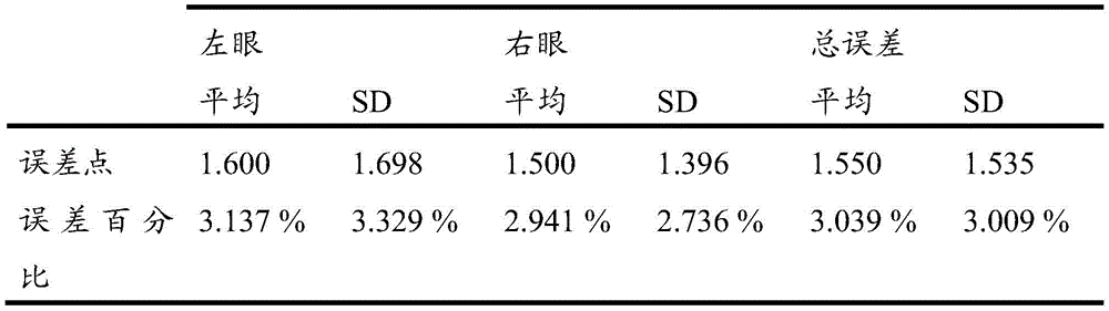
On the other hand, the visual field tests of 23 clinical patients were compared with the most recent hummphrey visual field analyzer (HFA) test routinely performed by subjects during their visit. The common 24 degree central zone was matched and compared between the two field of view test devices. Again, comparisons and relative error calculations are made on a point-by-point basis in a common central 24 degree zone, with zones outside this zone being judged by continuity with the central zone and the lack of independent response points. A summary of the calculation errors is listed in table 2.
Table 2: error calculation of the 23 patient visual field measurements.

An image remapping process is then performed which involves finding a new size and a new center for the displayed image to be displayed to the patient. By resizing and shifting the original input image, the output image is adapted to the bright field of the eye of the subject.
The field of view is binarized, setting all seen patient responses to 1, and keeping unseen responses to 0, resulting in a small binary image of 8X8 size. In other embodiments, smaller or larger binary image sizes may be used. A small region containing up to 4 connected pixels is removed from the binary field of view image. The 4 connected pixels represent a predetermined threshold for determining a small region, although in some embodiments a larger or smaller threshold may be used. These small regions are not taken into account in the image adaptation (fitting) process. The small regions that are ignored represent normal blind spots, no significant defects, or any random error response that may occur during the test of the subject's visual field.
Based on this interpolated binary field image, the region properties of the bright field are calculated. The calculated attributes of the bright regions include: 1) a bright region in pixels, 2) a bounding box of the region, 3) a weighted region centroid, and 4) a list of all the pixels that make up the bright region of the field of view. The bounding box is considered as the smallest rectangle that encloses all the pixels that make up the bright area. The center of mass of a region is calculated in terms of horizontal and vertical coordinates to calculate the centroid of the region. The value of this attribute corresponds to the new center of the output image, which corresponds to the amount of image shift required for mapping.
Using the list of pixels constituting the largest bright field, the width and height of all pixels forming the boundary of the bright field are calculated, as shown in fig. 37. For each line in the bright field, two boundary pixels are found and their vertical coordinates are subtracted to obtain the field width BF for that particular linewidths. This width calculation is iterated over all rows establishing the deemed bright field to calculate BFwidths. The same iterative process may be applied on the columns to compute BFheights. Subsequently, either of the two scaling equations may be used to determine a new size of the mapped output image; widthmapAnd Height mapAs shown in fig. 37.
Width can be calculated using a sizing equationmap:

Heightmap1=median(BFhegiths),
Wherein BFwidthsAnd BFheightsRespectively, the calculated width and height of the bright field boundary pixels. This scaling method calculates the new output image size as the median of the bright field sizes in each direction, centered at the new image center, as obtained above. A median measure is used instead of an average to avoid any size-adjusted skew (skewness) associated with too large or too small bright field sizes. The mapping behavior of this method is to fit the image in the most bright areas possible, but since this method does not maintain the aspect ratio, image stretching or compression may occur.
Height can be calculated using the resizing equationmap:


Wherein IsizeIs the interpolated image size (output image size), BXwidths,BXheightsIs the width and height of the bounding box. The sum of the numerators in the equation approximates the calculated bright field region in the horizontal and vertical directions, respectively. Thus, dividing these sums by the square of the output image size provides an estimate of the scaled image area to be mapped in each direction. These ratios are then multiplied by the corresponding bounding box sizes previously calculated. The mapping behavior of this method is to fit the image in the maximum bright field while trying to maintain the aspect ratio of the output image. Incorporating the dimensions of the bounding box into this calculation helps to achieve this effect. However, maintaining the aspect ratio may not result in all defective field of view patterns.
In one embodiment, the AI system may utilize two equations and several, if not hundreds, of different equations in the optimization process to see which will allow more of the viewing field to fit the image. Based on the operator's feedback, the system may learn to favor one equation over another based on the particular field of view to be corrected.
These remapping techniques are used to identify the threat object tests. 23 subjects were tested for a remapping method using a test image that included a safety hazard, the car in this test. The test image is selected to test the four major quadrants of the field of view as shown in fig. 38. The test image is remapped for display to the subject using the field of view example. The subject is tested by displaying an image of an incoming car. The subject cannot see the car before the remapped image is displayed, as shown in fig. 39A and 39B, fig. 39A showing the image the subject sees without remapping, and fig. 39B showing the image seen after remapping. Our preliminary study showed that 78% of the subjects (18 out of 23) were able to identify no safety risks that we helped them could not identify. Some subjects tested two eyes separately, so there were 33 eye tests. Visual assistance of 23 out of 33 eyes was found to be effective in helping the subject identify the simulated risk of entry (P ═ 0.023).
As represented, in some embodiments, referring to fig. 1A, the testing subsystem 122 may determine one or more defective visual field portions of the user's visual field based on the user's eye response to a set of stimuli displayed by the user or the user's eye's lack of response to the set of stimuli (e.g., eye movement response, pupil size response, etc.). In some embodiments, one or more movement stimuli may be dynamically displayed to the user as part of a visual test presentation, and the response or lack of response to the stimuli may be recorded and used to determine which portion of the user's field of view is intact. As an example, in the dynamic portion of the visual test presentation, the recording of the response to the patient's eye may begin after the stimulus is displayed in the visual test presentation and continue until the stimulus disappears (e.g., the stimulus may move from a starting point to a central point of the visual test presentation and then disappear). As another example, during a visual test presentation, when it is determined that the patient identified a stimulus (e.g., the patient's gaze direction changes to the current location of the stimulus), the stimulus may be removed (e.g., disappears from the patient's view). Thus, the duration of the visual test presentation may be shortened and the interactivity enhanced (e.g., providing the patient with a feeling of playing a game rather than diagnosing a visual deficit). Based on the above-described indications (response or lack of response to the set of stimuli), the testing subsystem 122 may automatically determine a defective visual field portion of the user's visual field.
In some embodiments, the testing subsystem 122 may determine one or more defective field of view portions of the user's field of view, and the vision subsystem 124 may provide an enhanced image or cause adjustment of one or more configurations of the wearable device based on the determination of the defective field of view portions. As an example, the enhanced image may be generated or displayed to the user such that one or more given portions of the enhanced image (e.g., a region of the enhanced image corresponding to a macula region or a region within a macula region of a field of view of the user's eye) are outside of the defective field of view portion. As another example, a position, shape, or size of one or more display portions of the wearable device, a brightness, contrast, saturation, or sharpness level of such display portions, a transparency of such display portions, or other configurations of the wearable device may be adjusted based on the determined defective field of view portion.
Fig. 4 illustrates a process 400, which process 400 illustrates an example implementation of a test mode and a subsequent vision mode. At block 402, in a test mode, data is obtained from a diagnostic device, such as an image sensor embedded within an eyewear device, and other user input devices, such as a cellular phone or tablet PC. At block 404, test mode diagnostics may be performed to detect and measure ocular abnormalities (e.g., visual field defects, eye misalignments, pupil movement and size, pattern images of corneal or retinal surface reflections, etc.) from the received data. In an example, the control program and algorithm were implemented using MATLAB R2017b (MathWorks, nattokk, massachusetts, usa). In various embodiments, the subject or tester may be provided with the option to choose to test each eye separately, or to test both eyes sequentially in one run. In some embodiments, the test pattern may include an applied fast threshold strategy that includes contrast step stimulation using a stimulation sequence covering a central radius of 20 degrees or more at predetermined locations. As an example, the test pattern may include an applied fast threshold strategy that includes four contrast step stimuli covering a central 40 degree radius with 52 stimulation sequences at predetermined locations, as discussed herein with reference to fig. 35-36. As another example, the test mode may include automatically determining a visual deficit (e.g., a deficient visual field portion) based on one or more responses of the user's eye to a set of stimuli displayed by the user or a lack of such responses of the user's eye to the set of stimuli (e.g., eye movement responses, pupil size responses, etc.), as described herein.
At block 406, the determined diagnostic data may be compared to a database or dataset storing corrective configurations for compensating identifiable ocular lesions (e.g., fig. 16 and related discussion).
The identified modified configurations may then be personalized for the individual, for example, to compensate for visual axis differences, visual field defects, light sensitivity, double vision, variations in image size between eyes, image distortion, vision degradation.
The personalized configurations may be used by block 408 to process the image along with real-time data (e.g., using an image processor, a scene processing module, and/or a vision module). The real-time data may include data detected by one or more inwardly directed image sensors 410, provide pupil tracking data, and/or from one or more outwardly directed image sensors including one or more field of view cameras 412 for capturing a field of view screen. At block 414, real-time image rectification may be performed and the image may be displayed (block 416) on an eyewear device, either as a recreated digital image, an augmented reality image that penetrates the eyewear device and is overlaid with rectified portions, or an image projected onto the retina of the subject. In some examples, the operations of block 414 are performed in conjunction with a calibration mode 418, where a user may adjust image rectification using a user interface (e.g., an input device that allows a user to control images and revision configurations). For example, the user may move the image of one eye to the side, up and down, or rotate (circle) to mitigate the double nature of vision. In the above or another example, the user may fine-tune the degree of transformation (e.g., fisheye, polynomial, or conformal) or translation of the field of view to allow for an expanded field of view without negatively impacting functional vision or causing unacceptable distortion, fine-tuning brightness and contrast, or reversing color.
FIG. 5 illustrates another example process 500, similar to process 400, for implementing a test mode and a vision mode. At block 502, data is collected regarding high and low order aberrations of pupil size, degree of accommodation, and gaze. In some embodiments, all or part of the data may be collected from an aberrometer, or the aberrations of the cornea or the entire ocular optical system may be detected by capturing an image of a pattern or grid projected on the cornea and/or retina and comparing it to a reference image. The collected data may be sent to a vision correction framework, which may determine a personalized corrective configuration at block 504 similar to block 406 described above. Blocks 508-518 perform similar functions as corresponding blocks 408-418 of process 400.
Fig. 8 illustrates a workflow 800 showing a testing module 802 that generates and presents a plurality of visual stimuli 804 to a user 806 via an eyewear device. The user 804 has a user device 808, through which user device 808 the user can interact to provide an input response to the test stimulus. In some examples, user device 808 may include a joystick, electronic clicker, keyboard, mouse, gesture detector/motion sensor, computer, phone such as a smartphone, dedicated device, and/or tablet PC through which a user may interact to provide an input response to a test stimulus. The user device 808 may also include a processor and memory storing instructions that, when executed by the processor, generate GUI displays for interaction by a user. The user device 808 may include memory, a transceiver (XVR) for transmitting and receiving signals, and an input/output interface for wired or wireless connection to the vision correction framework 810 (which may be stored on the image processing device). The vision correction frame 810 may be stored on an eyewear device, a user device, or the like-although in the illustrated example, the frame 810 is stored on an external image processing device. The framework 810 receives test pattern information from the test module 802 and user input data from the user device 808.
Fig. 9 illustrates a test mode process 900 that may be performed by the workflow 800. At block 902, a plurality of test stimuli are provided to a subject according to a test pattern protocol. The stimulus may include a text image, an object image, a flash of light, a pattern such as a grid pattern. The stimulus may be displayed to the subject or projected onto the retina and/or cornea of the subject. At block 904, the vision correction framework may receive detected data, such as data corresponding to a physical condition of the pupil (e.g., visual axis, pupil size, and/or limbus), from one or more inwardly directed image sensors. Block 904 may also include receiving user response data collected from the user in response to the stimulus. At block 906, pupil location conditions may be determined throughout the different stimuli, for example, by measuring location and misalignment differences between the different stimuli.
At block 908, astigmatism measurements may be taken over the entire field of view, which may include analysis of pupil misalignment data and/or ocular aberrations (e.g., projecting a reference image on the retina and cornea and comparing a reflected image from the retinal or corneal surface to the reference image). At block 910, the total ocular aberration may be determined (e.g., by projecting a reference image onto the retina and/or cornea, and then comparing a reflected image from the retinal or corneal surface to the reference image, such as described in fig. 31A, 32-34, and related discussion). At block 912, the distortion of vision, e.g., optical distortion such as coma, astigmatism, or spherical aberration, or distortion of vision from retinal disease, may be measured across the entire field of view. At block 914, field of view sensitivity may be measured across the field of view. In various embodiments of the process of FIG. 9, one or more of blocks 904-914 may be optional.
In some examples, the vision system herein may evaluate data from the test patterns and determine the type of ocular abnormality and the type of correction required. For example, FIG. 10 shows a process 1000 that includes an artificial intelligence correction algorithm mode that can be implemented as part of a test mode. At block 1002, a machine learning framework is loaded, an example framework may include: dimension reduction, ensemble learning, meta learning, reinforcement learning, supervised learning, Bayes, decision tree algorithm, linear classifier, unsupervised learning, artificial neural network, association rule learning, hierarchical clustering, cluster analysis, deep learning, semi-supervised learning and the like.
At block 1004, a field defect type is determined. Three example field defects are shown: uncompensated blind field of view 1006, partial blind spots with lower sensitivity 1008, and intact field of view 1010. Block 1004 determines a field defect and then applies a suitable correction scheme for the vision mode. For example, for an uncompensated blind region 1006, at block 1012, the vision correction framework tracks vision, such as by pupil tracking using an inwardly directed image sensor, and video tracks moving objects in the field of view (e.g., by an outwardly directed image sensor, such as an external camera). In the example shown, at block 1014, a safety hazard in or moving into the blind spot region is detected, for example, by comparing the location of the safety hazard to a mapped field of view having defects measured in the test mode. At block 1016, the object of interest may be monitored at a variety of locations including a central location and a peripheral location.
In the example of partial blind spot 1008, an augmented vision mode may be entered at block 1018 from which an object in the field of view is monitored by tracking a central portion of the field of view. At block 1020, an image segmentation algorithm may be employed to separate the object from the field of view. Augmented contours (outlines) may also be applied to the object and displayed to the user, where the contours coincide with the identified edges of the segmented object. With respect to an intact field of view 1010, at block 1022, customized corrective algorithms may be applied to correct aberrations, field detection, cross eyes, and/or visual distortion.
In some embodiments, testing subsystem 122 may determine a plurality of revised configurations associated with the user (e.g., during the presentation of the visual test, while displaying an enhanced presentation of the real-time image data to the user, etc.). In some embodiments, each correction configuration may include a set of correction parameters or functions to be applied to the real-time image data for a given context. As an example, the user may have a revised configuration for each set of eye characteristics (e.g., gaze direction, pupil size, limbus position, or range of other characteristics). As a further example, the user may additionally or alternatively have a revised configuration for each set of environmental characteristics (e.g., a brightness level of the environment, an ambient temperature, or a range of other characteristics).
Based on the currently detected eye-related or environment-related characteristic, a corresponding set of modification parameters or functions may be obtained and used for generating an enhanced representation of the real-time image data. As an example, a respective set of modification parameters or functions may be obtained (e.g., to apply to an image to modify the image for a user) based on a currently detected eye-related characteristic matching a set of eye-related characteristics associated with the obtained set of modification parameters or functions (e.g., the currently detected eye-related characteristic falls within the associated set of eye-related characteristics). In some embodiments, a set of modification parameters or functions may be generated based on currently detected eye characteristics or environmental characteristics (e.g., generating modification parameters for a particular purpose (ad-hoc), adjusting a currently stored modification configuration associated with a user for a given context, etc.).
In one use case, the wearable device (implementing the above operations) may automatically adjust the brightness of the enhanced presentation of real-time image data for one or more eyes of the user based on the respective pupil sizes (e.g., such adjustment is independent of the brightness of the surrounding environment). As an example, subjects with unequal pupil sizes have unequal pupil sizes, and those subjects have a single eye that is photosensitive and cannot tolerate the radiance that a healthy eye can tolerate. In this way, the wearable device may automatically adjust the brightness of each eye separately (e.g., based on the detected pupil size of the respective eye).
In another use case, the wearable device may detect pupil size, visual axis, optical axis, limbal location, line of sight, or other eye accommodation state (e.g., including changes to the foregoing), and may change the modification configuration based on the detected state. As an example, for subjects with higher order aberrations (e.g., refractive errors uncorrectable by glasses or contact lenses), the subject's aberrations are dynamic and change according to the pupil size and the accommodation state of the eye. The wearable device may detect the adaptation state by detecting signs of near reflections, such as miosis (reducing the size of the pupil) and convergence (pupil crossing inward). Additionally, or alternatively, the wearable device may include a pupil and a gaze tracker to detect a gaze direction. As another example, the aberrations of the eye vary depending on the size and position of the optical system aperture and can be measured relative to different pupil sizes and positions of the pupil and the visual axis. For example, the wearable device may measure irregularities on the cornea to determine higher order aberrations (e.g., based on the measurements) and calculate a corrective configuration to account for the higher order aberrations. For different sizes and positions of the pupil and the visual axis (or other eye accommodation state), different corrective configurations may be created and stored for future use to provide real-time enhancement. One or more of these detected inputs can enable the wearable device to provide enhancements to the user using a suitable revision configuration (e.g., a set of revision parameters or functions).
As another example, a wearable device may be used to correct presbyopia by automatically performing auto-focus on an image displayed to a user to provide near vision. Additionally, or alternatively, the wearable device may determine how far the target is (e.g., a target object or region) by quantifying the subject's achieved near reflection and the target-to-eye distance (e.g., via a sensor of the wearable device), and provide a suitable correction based on the quantified amount and the target distance.
As another example, the wearable device may be used to correct dual vision (e.g., related to strabismus or other conditions). The wearable device may monitor the user's eyes and track the user's pupils to measure the skew angle to shift the image projected by each eye (e.g., used in conjunction with detecting strabismus or other conditions). Because dual vision is typically dynamic (e.g., dual vision increases or decreases toward one or more fixations), the wearable device may provide suitable correction by monitoring the user's pupils and the user's gaze. For example, if the user has a problem moving the user's right pupil away from the user's nose (e.g., toward the user's facial edge), the user's double vision may increase when the user looks to the right and decrease when the user looks to the left. Thus, the wearable device may display an augmented presentation of real-time image data to each eye such that a first version of the augmented presentation displayed to one eye of the user reflects a displacement from a second version of the augmented presentation displayed to the other eye of the user (e.g., by an amount that is based on the pupil position and gaze direction) to dynamically compensate for a condition of the user (e.g., strabismus or other conditions) to prevent double vision for all potential gaze directions.
Although a prism may be applied to shift an image in front of a crossed eye (e.g., caused by strabismus or other conditions) to correct double vision, the prism cannot produce distortion of the image and is therefore not useful in correcting double vision caused by conditions that cause the image to tilt or rotate (e.g., rotational strabismus is a type of strabismus that causes the image received from both eyes to tilt or rotate). In some use cases, the wearable device may monitor the user's eyes to measure the degree of strabismus (e.g., including rotation) by detecting the relationship of the pupils, limbus, line of sight, or visual axis of the two eyes to each other. Additionally, or alternatively, the wearable device may perform such measurements by obtaining retinal images of both eyes and comparing structures of the retina and nerves with each other. In doing so, the wearable device can detect and measure the relative position and any rotational displacement of those eye structures. Such measurements may be provided to a predictive model to predict correction parameters for real-time image processing to correct defects and mitigate double vision. Continuous feedback may be obtained from sensors of the wearable device (e.g., pupil tracker, gaze tracker, retina image-based tracker, etc.) that may be used to change the revision configuration applied to the real-time image data in real-time. In a further use case, the user may also fine-tune the correction. As an example, an image may be displayed to the user on the user interface, and the user may move the image (or an object represented by the image) (e.g., using a joystick or other input device) until the image intersects in front of one eye, and rotate the object until the object overlaps the image seen by the other eye. In some embodiments, upon detecting the dual vision representation, and without any user input explicitly indicating that the image or amount or location of movement should be moved, the wearable device may automatically move the image that intersects in front of one eye (e.g., translate or rotate the image) to perform measurements or corrections related to dual vision.
As with other forms of strabismus, the displacement caused by rotational strabismus varies in real time based on the intended direction of motion of the paralyzed (or partially paralyzed) muscles associated with rotational strabismus and as the patient looks to one side or the other. By tracking eye characteristics, the wearable device may dynamically compensate for the user's condition by displaying an augmented presentation of real-time image data to each eye such that a first version of the augmented presentation displayed to one eye of the user reflects a displacement from a second version of the augmented presentation displayed to the other eye of the user (e.g., an amount of displacement based on pupil position and gaze direction).
In some embodiments, referring to fig. 1A, in obtaining feedback related to a set of stimuli (displayed to the user during presentation of the visual test), feedback related to one or more eyes of the user, feedback related to the user's environment, or other feedback, the testing subsystem 122 may provide the feedback to the predictive model, and may configure the predictive model based on the feedback. In some embodiments, the testing subsystem 122 may obtain a second set of stimuli (e.g., during a visual test presentation). As an example, the second set of stimuli may be generated based on processing of the set of stimuli by the predictive model and feedback related to the set of stimuli. The second set of stimuli may be additional stimuli derived from the feedback to further test one or more other aspects of the user's visual field (e.g., to aid in a finer correction or other enhancement of the user's visual field). In one use case, the testing subsystem 122 may cause the second set of stimuli to be displayed to the user (e.g., during the same visual presentation) and, in response, obtain further feedback related to the second set of stimuli (e.g., further feedback indicating whether or how the user sees one or more stimuli of the second set). Then, the testing subsystem 122 may provide further feedback related to the second set of stimuli to the predictive model, and may further configure the predictive model based on the further feedback (e.g., during presentation of the visual test). As an example, the predictive model may be automatically configured for the user based on (i) a representation of the user's response to one or more stimuli (e.g., of the set of stimuli, the second set of stimuli, or other sets of stimuli), (ii) a representation of the user's lack of response to such stimuli, (iii) an eye image captured during the presentation of the visual test, or other feedback (e.g., the predictive model may be personalized to the user based on feedback from the presentation of the visual test). For example, in one use case, the feedback represents one or more visual defects of the user, and the predictive model may be automatically configured to address the visual defects based on the feedback. As another example, the predictive model may be trained based on such feedback and other feedback from other users to improve the accuracy of the results provided by the predictive model (e.g., trained to provide the revised configuration described herein, trained to generate an enhanced presentation of real-time image data, etc.).
In some embodiments, vision subsystem 124 may provide real-time image data or other data (e.g., monitored eye-related characteristics) to the predictive model to obtain an enhanced image (derived from the real-time image data) and cause the enhanced image to be displayed. In some embodiments, the configuration of the predictive model may continue during the display of the enhanced image (derived from the real-time image data) based on further feedback continuously provided to the predictive model (e.g., periodically, according to a schedule, or based on other automatic triggers). As an example, the wearable device may obtain a real-time video stream from one or more cameras of the wearable device and cause the augmented images to be displayed on one or more displays of the wearable device (e.g., within less than a millisecond, less than a centimeter-second, less than a minute-second, less than a second, etc., of the real-time video stream captured by the cameras of the wearable device). In some embodiments, the wearable device may obtain the enhanced image from the predictive model (e.g., in response to providing real-time image data, monitored eye-related characteristics, or other data to the predictive model). In some embodiments, the wearable device may obtain the correction parameters or functions from the predictive model (e.g., in response to providing real-time image data, monitored eye-related characteristics, or other data to the predictive model). The wearable device may generate an enhanced image from the real-time image data using the modification parameter or function (e.g., a parameter used to transform or modify the real-time image data into a function of the enhanced image). As further examples, the modification parameters may include one or more transformation parameters, brightness parameters, contrast parameters, saturation parameters, sharpness parameters, or other parameters.
In one example, a vision correction framework having a machine learning framework with an AI algorithm may be used to create an automated personalized corrective configuration by applying transformations, translations, and resizing to the field of view to cause it to better fit the remaining functional field of view. The machine learning framework may include one or more of data collection, field of view classification, and/or regression models. To help record participant responses, quantitative scores, and feedback, a Graphical User Interface (GUI) and data collection program may be used.
With respect to transformations applied to images in visual mode, example transformations of a machine learning framework may include one or more of: 1) conformal mapping, 2) fish-eyes, 3) custom fourth-order polynomial transformation, 4) polar polynomial transformation (using polar coordinates), or 5) rectangular polynomial transformation (using rectangular coordinates) (see fig. 13).
With respect to panning applied to an image in a visual mode, examples may include one or more of the following. For central detection, a weighted average of the best center and the closest point to the center may be used. For example, the closest point of approach may be determined by finding the point closest to the central location. The optimal center may be determined by one or more of: 1) the centroid of the largest feature, 2) the center of the largest inscribed circle, square, diamond, and/or rectangle, or 3) the center of the local largest inscribed circle, square, diamond, and/or rectangle (e.g., fig. 14). For example, the frame may search for the largest shape, but alternatively to avoid moving away from the macular visual region, the frame may weight average the closest points in these ways.
In various embodiments, the AI algorithm may be initially trained using simulated field defects. For example, to train the AI algorithm, a field of view defect data set may be collected. For example, in one experimental protocol, a data set with 400 visual field defects was obtained from a glaucoma patient. The data set can be used to create simulated visual field defects on virtual reality glasses for presentation to normal subjects for grading. Feedback of the results obtained from the ranking can be used to train the algorithm.
For example, an AI algorithm may be used that automatically fits the input image to the region corresponding to the intact view field pattern for each patient. In various embodiments, the algorithm may include at least three degrees of freedom to remap the image, although more or fewer degrees of freedom may be used. In one example, the degrees of freedom include transformation, shifting, and resizing. The added image transformation can maintain the quality of the central region of the image corresponding to central vision, where the acuity is highest, while compressing the peripheral region with a sufficient amount of image quality at the periphery. This may be applied so that the overall image content produced is readily noticeable to the patient.
The image transformations included in the AI algorithm may include one or more conformal, polynomial, or fisheye transformations. In some embodiments, other transforms may be used. Machine learning techniques can be trained on the labeled data sets before performing their actual tasks. In one example, the AI algorithm may be trained on field of view data sets containing different types of peripheral defects. For example, in one experiment, the data set included 400 field defect patterns. The training phase is then guided by the normal participants to quantitatively score the remapped images generated by the AI algorithm.
Fig. 11 shows an image 1100 of a test image (stimulus) according to an example. The test image 1100 may be designed to measure acuity, peripheral vision, and/or peripheral vision. As shown in fig. 11, the test image is shown with five letters in the central region, four inner diamonds 1102 in the lateral central region, and eight outer diamonds 1104 in the peripheral region.
As described above, a large amount of data is required in order to be able to train the AI system. As an initial step, the defective binocular visual field may be used to simulate binocular vision of the patient, as shown in FIG. 12. Next, the simulated vision may be presented to the subject through an eyewear device. In this way, the input image can be manipulated using different image manipulations and then presented again to the subject to grade the modified vision. The corrected image may be further corrected and presented to the subject in a continuous correction process until an optimized corrected image is determined. Fig. 13 shows examples of different rectification transformations that may be applied to an image and presented to a user. Fig. 14 shows an example of a different translation method (shifting the image to fit it to the intact field of view). The intact field of view is white and the blind field of view is black.
AI systems may be designed using machine learning models such as artificial neural networks and Support Vector Machines (SVMs). In some examples, the AI system is designed to produce an estimated output including optimal image manipulation methods (e.g., geometric transformations and translations) by optimizing the AI system. In the vision mode, the vision system may present images manipulated according to the output image manipulation method to the patient through headphones so that the patient experiences the best possible vision based on his deficient field of view. A machine learning framework (also referred to herein as an "AI system") of the vision correction framework may be trained using the collected data (e.g., as described herein). A block diagram of an example AI system 1500 is shown in fig. 15.
The process 1600 of the AI system 1500 is illustrated in FIG. 16. The inputs to the system 1500 include a test image and a field of view image. The AI system 1500 estimates the best geometric transformation of the test image so that more detail can be presented through the field of view. The AI system 1500 then estimates the optimal translation of the test image such that the displayed image covers a substantial portion of the field of view. The test image is then transformed and translated as shown in fig. 17 and 18, respectively. Finally, in the case of training for simulation purposes only, the images are again combined with the field of view, but displayed directly to the patient during the testing phase. A screenshot of a graphical user interface presenting a field of view analysis summary is shown in fig. 19, which may include a final implementation of a field of view AI system that includes parameters to be applied to image transformations and translations of an image.
In an example implementation, an artificial neural network model is used to implement a machine learning framework ("AI system") on a vision correction framework. The AI system converts the field of view images into vectors. The AI system applies image transformations and predictions of translation parameters as output to images of a scene. These parameters are then used to manipulate the scene image. The AI system includes two hidden layers, where each hidden layer includes three neurons (i.e., cells) and one output layer. Fig. 20 shows one such example AI system model. In other examples, this AI system may also be extended to convolutional neural network models to obtain more accurate results. Fig. 21 and 22 illustrate example processes 2100 and 2200, respectively, of a test pattern application of a neural network and an AI algorithm optimization process using the neural network.
In some embodiments, referring to fig. 1A, in obtaining feedback related to a set of stimuli (displayed to the user during presentation of the visual test), feedback related to one or more eyes of the user, feedback related to the user's environment, or other feedback, the testing subsystem 122 may provide feedback to the predictive model, and may configure the predictive model based on the feedback. In some embodiments, further feedback may be continuously obtained and provided to the predictive model (e.g., periodically, according to a schedule, or based on other automatic triggers) to update the configuration of the predictive model. As an example, the configuration of the predictive model may be updated while displaying one or more enhancements of the real-time image data to the user.
In some embodiments, vision subsystem 124 may monitor characteristics associated with one or more eyes of the user (e.g., gaze direction, pupil size or response, limbus position, visual axis, optical axis, eyelid position or movement, head movement, or other characteristics) and provide eye characteristic information to the predictive model during enhanced presentation of real-time image data to the user. Additionally, or alternatively, the vision subsystem 124 may monitor characteristics related to the user's environment (e.g., the brightness level of the environment, the temperature of the environment, or other characteristics). As an example, based on eye or environmental characteristic information (e.g., representative of monitored characteristics), the predictive model may provide one or more correction parameters or functions that are applied to the real-time image data to generate an enhanced presentation of the real-time image data (e.g., present one or more enhanced images derived from the real-time image data to the user). In one use case, the predictive model may obtain correction parameters or functions (e.g., stored in memory or in one or more databases) based on currently detected eye characteristics or environmental characteristics. In another use case, the predictive model may generate a correction parameter or function based on the currently detected eye characteristics or environmental characteristics.
In some embodiments, referring to fig. 1A, vision subsystem 124 may help enhance the user's field of view (e.g., based on feedback related to a set of stimuli displayed to the user or other feedback) via one or more dynamic display portions on one or more transparent displays. As an example, the dynamic display portion may include one or more transparent display portions and one or more other display portions (e.g., of the wearable device or other device). In some embodiments, vision subsystem 124 may cause one or more images to be displayed on other display portions (e.g., such that the images are not displayed on transparent display portions). As an example, a user may see through a transparent display portion of the transparent display, but may not see through other display portions, but may see image presentations on other display portions of the transparent display (e.g., around or near the transparent display portion). That is, in some embodiments, a dynamic hybrid see-through/see-through display may be used. In this manner, for example, one or more embodiments may (i) avoid the bulkiness and bulkiness of typical virtual reality headsets, (ii) take advantage of the intact vision of the user (e.g., take advantage of the central vision of good acuity of the user if the user has intact central vision but defective peripheral field of view; take advantage of the peripheral vision of intact user if the user has intact peripheral vision but defective central field of view; etc.), and (iii) mitigate visual clutter that may result from typical augmented reality techniques that have an overlapping effect between transparent scenes and internally displayed scenes.
As an example, real-time image data may be obtained via the wearable device, and an augmented image may be generated based on the real-time image data and displayed on other display portions of the wearable device (e.g., display portions of the wearable device display that meet an opacity threshold or do not meet a transparency threshold). In some embodiments, vision subsystem 124 may monitor one or more changes associated with one or more eyes of the user and cause adjustments to be made to the transparent display portion of the transparent display based on the monitoring. By way of example, the monitored changes may include eye movement, changes in gaze direction, changes in pupil size, and other changes. One or more positions, shapes, sizes, transparencies, brightness levels, contrast levels, sharpness levels, saturation levels, or other aspects of the transparent display portion or other display portion of the wearable device may be automatically adjusted based on the monitored changes.
In one use case, referring to fig. 24A, wearable device 2400 can include a transparent display 2402 that is dynamically configured with a transparent perimeter portion 2404 and an opaque central portion 2406 such that light from the user's environment can directly penetrate through the transparent perimeter portion 2404, but not the opaque central portion 2406. For a patient 2306 diagnosed with a central field of view abnormality, the above-described dynamic configuration enables such a patient to view the actual uncorrected environmental view using their intact peripheral field of view and present a corrected rendition 2406 of the central region on the opaque central portion 2406.
In another use case, referring to fig. 24B, the wearable device 2400 may include a transparent display 2402 that is dynamically configured with an opaque perimeter portion 2414 and a transparent central portion 2416 such that light from the user's environment may pass directly through the transparent central portion 2416, but not through the opaque perimeter portion 2414. For patients with peripheral field abnormalities, the above-described dynamic configuration enables such patients to view the actual uncorrected environmental view using their central field of view intact, and to present a corrected rendition of the peripheral region on the opaque peripheral portion 2414. In each of the use cases described above, with reference to fig. 24A and 24B, one or more positions, shapes, sizes, transparencies, or other aspects of the transparent display portions 2404, 2416 or the opaque display portions 2406, 2414 may be automatically adjusted based on changes associated with one or more eyes of the user monitored by the wearable device 2400 (or other component of the system 100). Additionally, or alternatively, one or more brightness levels, contrast levels, sharpness levels, saturation levels, or other aspects of the opaque display portions 2406, 2414 may be automatically adjusted based on changes associated with one or more eyes of the user monitored by the wearable device 2400. In some cases, for example, to dynamically adapt the user's field of view with reduced brightness, the user's pupils and gaze (or other eye characteristics) may be monitored and used to adjust the brightness level of the portion of the opaque display portions 2406, 2414 (e.g., additionally or alternatively, increase the brightness level of the portion of the enhanced image corresponding to the region of reduced brightness of the user's field of view).
By way of example, referring to fig. 24C, based on the determination of the user field of view (e.g., including defective field of view portions, intact field of view portions, etc., as represented by field of view plane 2432), an enhanced image (e.g., as represented by remapped image plane 2434) may be generated, as described herein. The augmented image may be displayed to the user on one or more opaque display portions in an opaque region 2438 of the display (e.g., as represented by selectively transparent screen plane 2416) such that the displayed augmented image augments the user's view of the environment through a transparent region 2440 of the display.
In one use case, referring to fig. 24C, the selectively transparent screen plane 2436 can be aligned with the other planes 2432 and 2434 via one or more eye tracking techniques. As an example, an eye tracking system (e.g., of wearable device 2400 or other device) may calibrate a user according to the user's personalized intact field of view to ensure proper image projection. The eye tracking system may continuously acquire gaze coordinates (e.g., periodically, according to a schedule, or other automatic trigger). A coordinate transformation may be performed to move the eye by a spherical coordinate (theta,  ) Converted to cartesian coordinates (x, y) of the display. Thus, the controller of the device may determine the central location of the image to be displayed. The camera image will be truncated and shifted to match the acquired gaze vector direction (e.g., fig. 24C). The same cartesian coordinates may be sent to a selectively transparent screen controller to make the region corresponding to macular vision in the current gaze direction transparent and allow central visual acuity to be used. In some cases, low pass filtering may be performed on the gaze data to remove minor eye movements (e.g., minor eye movements caused by the eye never being completely stationary, but constantly moving and stretching occurs even at gaze), which may otherwise result in an unstable image being displayed to the user.
As described above, in some embodiments, the wearable device may be configured to selectively control the transparency of the display area of the monitor, such as a screen, glass, film, and/or layered media. Fig. 23 shows an example process 2300 of implementing test and vision modes and using a custom reality eyewear device, which may be manipulated using macular (central) versus peripheral vision.
In some examples, a custom reality eyewear device (e.g., fig. 40A-40C) includes transparent eyewear for superimposing a rectified image onto a visible scene. The glasses may include a monitor comprising a screen with controllable transparency onto which images may be projected for display. In one example, the display comprises a heads-up display. In various embodiments, a custom reality eyewear device includes eyewear having a controllable layer for superimposing a rectified image onto a scene visible through the eyewear. The layers may include glass, ceramic, polymer, film, and/or other transparent materials arranged in a layered configuration. The controllable layers may comprise one or more electrically controlled layers that allow the transparency to be adjusted over one or more portions of the field of view, for example in a pixel-specific controlled manner. In one embodiment, pixels or cells may be included that are individually and specifically controllable (e.g., by current, field of view, or light). The controllable layer may be a surface transparency of the eyewear device that can be controlled to adjust the contrast of one or more portions of the field of view, color filtering on a portion, zooming in/out on a portion, focus on a portion, display an image to block or allow light from the environment at a particular location of the field of view. If there is a portion of the field of view (e.g., a portion of the peripheral field of view or a portion or portion of the macular field of view, a portion of which is the macula and a portion of which is the peripheral field of view) for manipulation to enhance the vision of the subject, the transparency of that portion of the glass may be reduced to block the view of the environment through that portion of the glass and allow the patient to more clearly see the manipulation image displayed along that portion of the glass. In various embodiments, the vision system or custom reality eyewear device may dynamically control the transparent region to allow a subject to naturally view the environment while redirecting the eyes through eye movement, not just head movement. For example, pupil tracking data (e.g., pupil and/or gaze tracking) may be used to modify the reduced transparency glass portion such that the reduced transparency region is translated relative to the subject's eye.
For example, glass transparency in eyewear devices including custom reality glasses may be controllably adjusted to block light from portions of the field of view corresponding to where image rectification is performed (e.g., in a central region or a peripheral region). Otherwise, the subject may see the manipulated image and see through it, and perceive the underlying actual field of view in that region. Such light blocking may be achieved by a photochromic glass layer within the eyewear device. Furthermore, the eyewear device may change the location of the region of reduced glass transparency by measuring eye (pupil) movement using an inwardly directed image sensor and compensating based on such movement by processing in a vision correction framework. In one example, the display screen of the monitor includes pixels or cells that include electro-ink technology and can be individually and specifically controlled to cause the electric field to modify the placement of ink within the cells to modify transparency and/or generate displayed pixels. In an example implementation, fig. 40A shows customized reality glasses 4000 formed for a frame 4002 and two transparent glass components 4004. As shown in fig. 40B and 40C, transparent glass subassembly 4004 has an embedded electronically controllable corrective layer 4006, which corrective layer 4006 can be controlled from fully transparent to fully opaque, which corrective layer can be a digital layer capable of generating a corrective image to overlay or replace a portion of the field of view of eyewear 4000. The correction layer 4006 may be connected to the image processing apparatus 4010 on the frame 4002 through an electrical connection 4008.
Referring specifically to process 2300 of fig. 23, at block 2302, test pattern data may be received by the vision correction framework and, at block 2304, field distortions, defects, aberrations, and/or other ocular abnormalities, and their locations, may be determined.
For a diagnosed central field of view anomaly 2306, at block 2308, the custom reality eyewear device may allow an image from the environment to penetrate through its glass into the user's peripheral field of view (e.g., fig. 24A). As shown, the customized reality glasses device 2400 can have a multiple layer glass viewfinder 2402. The peripheral region 2404 may be configured to be transparent to allow light to penetrate the region, thereby allowing the subject to view the actual uncorrected environment. At block 2312, a central region 2406 of the environment may be rendered opaque by the eyewear device 2400 and a corrected rendition of the central region may be presented to the user, for example, by displaying to the user using, for example, the corrections of fig. 13, 14, 17, and 18.
For the diagnosed peripheral field of view anomaly 2308, at block 2314, a central region 2416 (e.g., fig. 24B) of the environment is allowed to penetrate through the transparent portion of the eyewear device 2400 and the transparency of the peripheral region 2414 is modified to be blocked so that a corrected peripheral version image may be displayed within the peripheral region 2414, for example, using the corrective transformation herein.
In some embodiments, referring to fig. 1A, vision subsystem 124 may help enhance the user's field of view by projecting onto a selected portion of the user's eyes (e.g., based on feedback related to a set of stimuli displayed to the user or other feedback). As discussed herein, the enhanced representation of the real-time image data may be displayed to the user by projecting the enhanced representation (e.g., a modified image derived from the real-time image data) onto the eyes of the user. Additionally or alternatively to using dynamic display portions on the screen (e.g., to enable the user to see through one or more other portions of the screen when the user sees the modified real-time image data displayed on one or more portions of the screen), the modified image data may be projected to one or more portions of the user's eye (e.g., one or more portions of the user's retina) while avoiding the projection of the modified image data to one or more other portions of the user's eye (e.g., one or more other portions of the user's retina).
In some embodiments, the modified image data may be projected to one or more intact portions of the field of view of the user's eyes while avoiding projection of the modified image data to one or more other intact portions of the field of view of the user's eyes. As an example, with respect to avoiding other intact portions of the field of view onto which the modified image data is projected, light from the user's environment may penetrate the user's retina (e.g., without any significant interference from light emitted by the projector), thereby allowing the user to see the environment via such other intact portions of the field of view. On the other hand, with respect to the intact view field portion of the image data being projection corrected, the projected light prevents the user from seeing the environment via the portion projected to the user's intact view field. However, by projecting the modified real-time image data to those portions of the user's eye that are intact fields of view, the system allows the user's field of view to be augmented using the modified real-time image data (e.g., in a manner similar to the way the user's field of view is augmented using the dynamic display portion).
In some embodiments, vision subsystem 124 may monitor one or more changes associated with one or more eyes of the user and adjust one or more projection portions of the projector based on the monitoring (e.g., portions including laser diodes, LED diodes, etc. emitting a threshold amount of light visible to the user's eyes). As an example, as with adjusting the dynamic display portion on the screen, the monitored changes may include eye movement, changes in gaze direction, changes in pupil size, or other changes. One or more of the position, shape, size, brightness level, contrast level, sharpness level, saturation level, or other aspects of the projection portion or other portion of the projector may be automatically adjusted based on the monitored changes.
In one use case, the wearable device may include a projector configured to selectively project an augmented presentation (e.g., a modified image derived from the real-time image data) to one or more portions of the user's eye (e.g., one or more portions of each retina of the user corresponding to the user's intact vision field) while avoiding projecting modified image data to one or more other portions of the user's eye (e.g., one or more other portions of each retina of the user corresponding to the user's intact vision field). In some cases, the alignment of such selective projection planes may be aligned with other planes (e.g., field of view planes, remapped image planes, etc.) via one or more eye tracking techniques (e.g., one or more techniques similar to those described in fig. 24C with respect to using dynamic display portions on a screen).
Referring to fig. 24A, wearable device 2400 can include a transparent display 2402, the transparent display 2402 dynamically configured with a transparent perimeter portion 2404 and an opaque central portion 2406 such that light from the user's environment can directly penetrate the transparent perimeter portion 2404, but not the opaque central portion 2406. For patients 2306 diagnosed with central field of view abnormalities, the above-described dynamic configuration enables such patients to view actual uncorrected environmental views using their intact peripheral field of view and render a corrected rendition of the central region on the opaque central portion 2406.
In another use case, referring to fig. 24B, the wearable device 2400 can include a transparent display 2402, the transparent display 2402 being dynamically configured with an opaque perimeter portion 2414 and a transparent central portion 2416 such that light from the user's environment can directly penetrate the transparent central portion 2416, but not the opaque perimeter portion 2414. For patients with peripheral field of view abnormalities, the above-described dynamic configuration enables such patients to use their intact central field of view to view an actual uncorrected view of the environment and present a corrected rendition of the peripheral region on the opaque peripheral portion 2414. In each of the use cases described above, with reference to fig. 24A and 24B, one or more positions, shapes, sizes, transparencies, or other aspects of the transparent display portions 2404, 2416 or the opaque display portions 2406, 2414 may be automatically adjusted based on changes associated with one or more eyes of the user monitored by the wearable device 2400 (or other component of the system 100). Additionally, or alternatively, one or more brightness levels, contrast levels, sharpness levels, saturation levels, or other aspects of the opaque display portions 2406, 2414 may be automatically adjusted based on changes associated with one or more eyes of the user monitored by the wearable device 2400. In some cases, for example, to automatically adapt to a user's reduced-brightness field region, the user's pupils and gaze (or other eye characteristics) may be monitored and used to adjust the brightness level of portions of the opaque display portions 2406, 2414 (e.g., additionally or alternatively to increase the brightness level of the enhanced image portions corresponding to the reduced-brightness regions of the user's field of view).
In some embodiments, testing subsystem 122 may monitor, via two or more user interfaces (e.g., on two or more displays), one or more eye-related characteristics related to the user's eyes during the visual test presentation and determine visual defect information for the user's one or more eyes based on the eye-related characteristics occurring during the visual test presentation. As an example, testing subsystem 122 may cause presentation of one or more stimuli at one or more locations on at least one user interface and generate visual deficit information for the user's eye based on one or more eye-related characteristics of the eye that occur at the time of presentation of the stimuli. In some embodiments, a deflection measurement of the eye may be determined based on eye-related characteristics (represented by monitoring that occurs while the stimulus is presented) and used to provide correction or other enhancement to the eye. As an example, the deflection measurement may represent the deflection of an eye relative to another eye, and the deflection measurement may be used to determine and correct double vision or other visual defects. As an example, the amount of movement represents the amount of eye intersection (e.g., strabismus), and the direction (or axis) of movement represents the type of strabismus. For example, if the eye movement is from "outer" to "inner", this means that the strabismus is cross-to-outer (e.g., outer strabismus). Thus, in some embodiments, dual vision may be automatically determined and corrected via the wearable device.
In some embodiments, testing subsystem 122 may determine the measure of deflection or other visual deficit information for the first eye of the user by (i) causing a stimulus to be presented at a location on the first user interface for the first eye when the stimulus intensity of the second user interface for the second eye of the user does not satisfy the stimulus intensity threshold, and (ii) determining the visual deficit information based on one or more eye-related characteristics of the first eye that occur at the time of presentation of the stimulus. By way of example, presentation of a stimulus on the first user interface may occur when the stimulus is not presented on the second user interface. In one use case, if a first eye (e.g., the right eye) crosses externally before such stimulus presentation on the first user interface (e.g., fig. 25D), by presenting the stimulus in front of only the first eye (e.g., only the right eye), the first eye will instinctively move toward and gaze on the stimulus location (e.g., in less than one second of time) because the second eye (e.g., the left eye) will lose any dominance because nothing is visible. The testing subsystem 122 may measure the corrective movement of the first eye (and other changes in the eye-related characteristic of the first eye) to determine a deflection measure for the first eye. As an example, the amount of movement that the first eye occurs when such a stimulus is presented may correspond to the amount of intersection of the first eye.
In some embodiments, the testing subsystem 122 may determine a measure of deviation or other visual deficit information for a first eye of the user by (i) causing a stimulus to be presented at a given time at a corresponding location on a first user interface for the first eye and a corresponding location on a second user interface for a second eye, and (ii) determining the visual deficit information based on one or more eye-related characteristics of the first eye that occur at the time of presentation of the stimulus. As an example, the target stimulus may be presented at a central location on both user interfaces or at another corresponding location on both user interfaces. In one use case, when a stimulus is presented in front of both eyes (e.g., fig. 25B), the dominant eye (e.g., the left eye in fig. 25B) will instinctively move to the corresponding position and gaze at the target stimulus (e.g., in less than one second). Although the other eye (e.g., the right eye in fig. 25B) will also move, it will not instinctively gaze on the target stimulus because the other eye crosses outward, resulting in double vision for the user. For example, when the other eye moves instinctively, the instinctive movement will cause the gaze direction of the other eye to face a different location. However, when the other eye of the user is focused on looking at the target stimulus, the other eye will move and gaze at the target stimulus presented at the corresponding location on the user interface of the other eye. Since the target stimulus is presented at the respective locations on both user interfaces, the dominant eye will remain dominant and continue to gaze at the target stimulus presented at the respective locations on the dominant eye user interface. The testing subsystem 122 may measure corrective movement of the other eye (and other changes in the eye-related characteristic of the other eye) to determine a measure of deflection of the other eye (e.g., the amount of movement of the other eye may correspond to the amount of cross-over of the other eye).
In some embodiments, after obtaining a deflection measurement or other visual deficit information for the first eye of the user by measuring a change in an eye-related characteristic of the first eye (e.g., a movement of the first eye that occurs when a stimulus is presented at a corresponding location on the first user interface for the first eye), the testing subsystem may cause the stimulus to be presented at a modified location on the first user interface for the first eye display. By way of example, presentation of the stimulus at the modified location occurs when no stimulus is presented on the second user interface for the second eye (or at least when the stimulus intensity of the second user interface does not meet the stimulus intensity threshold such that the second eye does not react to any stimulus on the second user interface). Based on the change in one or more eye-related characteristics of the first eye or the second eye in the presentation of the corrected position not exceeding a change threshold, the testing subsystem 122 may validate a deflection measurement or other visual defect information for the first eye. As an example, upon presentation of the stimulus at the corrected location, a deflection measurement of the first eye may be confirmed based on movement of the first eye not exceeding a movement threshold (e.g., no movement or other movement threshold). Additionally, or alternatively, a deflection measurement of the first eye is confirmed based on the movement of the second eye not exceeding the movement threshold.
In some embodiments, the testing subsystem 122 may generate one or more corrective configurations associated with the user based on one or more deflection measurements or other visual deficit information (e.g., obtained via one or more visual test presentations) of one or more eyes of the user. As an example, each modification configuration may include modification parameters or functions for generating an enhanced image from the real-time image data (e.g., parameters for transforming or modifying the real-time image data into a function of the enhanced image). Thus, in some embodiments, vision subsystem 124 may generate modified video stream data to be displayed to the user based on (i) the video stream data representative of the user environment and (ii) a modified configuration associated with the user.
As examples, a visual test may be performed to determine whether there is a deflection of the user's eyes, to measure the deflection of the user's eyes, or to generate one or more corrective configurations for the user's eyes. In one use case, referring to fig. 25A, when a target stimulus 2502 is presented to a patient (e.g., a patient without crossed eyes) at a central location of the left and right displays 2503a and 2503b of the wearable device, both eyes (e.g., the right and left eyes 2504a and 2504b) will instinctively move and gaze on the target stimulus 2502 at each wearable display central location, and thus, the patient can only see one target stimulus 2502. Thus, based on the eye responses described above, the testing subsystem 122 may determine that the user does not have dual vision.
In another use case, referring to fig. 25B, when target stimulus 2502 is presented to a patient with crossed eyes at a central location of the left and right displays of the wearable device, one eye (e.g., the dominant eye) will instinctively move to the central location and gaze on target stimulus 2502 (e.g., left eye 2504B instinctively gaze on target stimulus 2502). Although the other eye (e.g., the right eye 2504a) may also move, it will not gaze at the target stimulus 2502 because the other eye crosses outside, causing the user to see two (e.g., the user sees two target stimuli instead of one). For example, when the other eye moves instinctively, the instinctive movement will cause the gaze direction of the other eye to face a different location. Based on the eye responses described above, the testing subsystem 122 may determine that the user has dual vision. However, in a further use case, when the user focuses on looking at the stimulus 2502 with the other eye of the user (e.g., the intersecting right eye 2504a), the other eye will move and gaze at the target stimulus 2502 displayed at a central location on the user interface of the other eye. Since the target stimulus 2502 is presented at a central location on the displays 2503a and 2503b, the leading eye will remain dominant and continue to gaze at the target stimulus 2502 presented at the central location on the display of the leading eye. Corrective movement of the other eye (and other changes in the eye-related characteristic of the other eye) may be measured to determine a measure of the deviation of the other eye (e.g., the amount of movement of the other eye may correspond to the amount of intersection of the other eye).
In another use case, referring to fig. 25C, at time t1, a stimulus (e.g., target stimulus 2502) may be presented to left eye 2504b only in a central location by presenting the stimulus on left display 2503b and not presenting the stimulus on right display 2503 a. For example, if the stimulus is presented to both eyes 2504a and 2504B at a central location (e.g., time t0 immediately prior to presentation of the stimulus at time t 1), as shown in fig. 25B, just prior to presentation of the stimulus to left eye 2504B, left eye 2504B will not move because left eye 2504B has already gazed at the central location. However, if the left eye 2504b is not already gazed at the central location, presentation of stimulation to only the left eye 2504b will cause the left eye 2504b to instinctively move to the central location and gaze on the target stimulation 2502.
As shown in fig. 25D, a stimulus (e.g., target stimulus 2502) may be presented to only the right eye 2504a (e.g., at time t2) in a central location by presenting the stimulus on the right display 2503a and not presenting the stimulus on the left display 2503 b. Because the left eye 2504b is not stimulated (e.g., nothing is visible), the left eye 2504b will lose dominance and therefore the left eye 2504b will move outward due to the take over of the right eye 2504 a. When the target stimulus 2502 is presented only to the right eye 2504a, the right eye 2504a will instinctively take over and move to gaze the central location. The testing subsystem 122 may measure the movement of the right eye 2504a to determine a skew measurement of the right eye 2504a (e.g., the amount of movement may correspond to the amount of cross-over of the right eye 2504 a).
As shown in fig. 25E, a stimulus (e.g., a target stimulus 2502) may be presented to both eyes 2504a and 2504b at a central location (e.g., at time t3) by presenting the stimulus on left and right displays 2503b and 2503 a. If the intersections are alternating (neither eye dominates), the right eye 2504a will remain centered and the left eye 2504b will remain intersected. However, if left eye 2504b is the dominant eye (as represented in fig. 25E), left eye 2504b will instinctively move and gaze at a central location. Movement of left eye 2504b will cause right eye 2504a to cross, resulting in the gaze direction of right eye 2504a facing a different location. The testing subsystem 122 may measure the movement of the left eye 2504b to determine or confirm a skew measurement of the right eye 2504a (e.g., the amount of movement of the left eye 2504b may correspond to the amount of skew of the right eye 2504 a).
In a further use case, further tests may be performed to confirm the skew measurements of the non-dominant eye. For example, as represented in fig. 25F, after one or more of the above-described steps described with reference to fig. 25B-25E, a stimulus (e.g., target stimulus 2502) may be presented to only left eye 2504B (e.g., at time t4) in a central location by presenting the stimulus on left display 2503B and not presenting the stimulus on right display 2503 a. To the extent that the left eye 2504b loses gaze (e.g., due to the presentation in fig. 25E), the presentation in fig. 25F will cause the left eye 2504b to instinctively move to obtain gaze at a central location. Movement of left eye 2504b will cause right eye 2504a to cross, resulting in the gaze direction of right eye 2504a facing a different location. As represented in fig. 25G, based on the deflection measurement of the right eye 2504a, a corrected location for presenting a stimulus to the right eye 2504a may be determined. Thus, when the target stimulus 2502 is presented at a central location on the left display 2503b, the target stimulus 2502 may be presented at a modified location on the right display 2503a (e.g., at time t 5).
Subsequently, referring to fig. 25H, the target stimulus 2502 may be presented only to the right eye 2504a (e.g., at time t6) by presenting the target stimulus 2502 at the modified location on the right display 2503a and not presenting the stimulus on the left display 2503 b. Specifically, for example, target stimulus 2502 is deflected to the right by the same amount as the deflection measured in one or more of the above-described steps described with reference to fig. 25B-25E. If the skew measurement is accurate, the right eye 2504a will not move. If the skew measurement is inaccurate, the right eye 2504a will move slightly, and the amount of movement may be measured by the wearable device (e.g., the wearable device's pupil tracker), which may be used to fine tune the skew. As an example, the measured and corrected positions may be used to determine an updated corrected position to present a stimulus to the right eye 2504a, and one or more of the steps described with reference to fig. 25F-25H may be repeated using the updated corrected position. Additionally, or alternatively, one or more of the steps of fig. 25B-25E may be repeated to re-determine the deflection measurement of one or more eyes of the user (e.g., re-determine the deflection measurement of the right eye 2504 a). Referring to fig. 25I, the target stimulus 2502 may then be presented to both eyes 2504a and 2504b (e.g., at time t7) by presenting the target stimulus 2502 at the corrected location on the right display 2503a and the central location on the left display 2503 b. Since the target stimulus 2502 in front of the right eye 2504a is deflected to the right according to a deflection measurement (e.g., as determined or confirmed in one or more of the above-described steps), the user no longer sees both, thereby providing automatic correction for the dual vision of this patent.
In some embodiments, a visual test may be performed to determine which eye of the user is a deviated eye. Based on such a determination, a deflection of the deflected eye may be measured, and the deflection measurement may be used to generate a correction configuration to correct the deflection of the user's vision. As an example, testing subsystem 122 may cause a stimulus to be presented at a first location on a first user interface for a first eye and a first location on a second user interface for a second eye at a given time. The testing subsystem 122 may detect a lack of gaze of the first eye at the first location upon presentation of the stimulation on the first user interface. Based on the detection of the lack of gaze of the first eye, the testing subsystem 122 may determine that the first eye of the user is a deviated eye. As an example, referring to fig. 25B, when target stimulus 2502 is presented to a patient with crossed eyes at a central location of the left and right displays of the wearable device, one eye (e.g., the leading eye) will instinctively move to the central location and gaze at target stimulus 2502 (e.g., left eye 2504B instinctively gaze at target stimulus 2502). Although the other eye (e.g., right eye 2504a) may also move, it does not gaze at target stimulus 2502 because the other eye is crossed on the outside, causing the user to see a ghost image (e.g., the user sees two target stimuli instead of one). Based on this detected lack of gaze, the other eye may be determined to be a deviated eye.
In some embodiments, when the eyes look in different gaze directions, a vision test may be performed to detect how much double vision is in each gaze direction. In this manner, a particular type of strabismus (e.g., non-common strabismus) can be diagnosed and corrected. For example, in a patient with paralysis of the eye muscles, the deviation (squint angle) between the two eyes is greater when the eyes look in the direction of movement of the muscles. For example, if the muscles of the left eye that are outward are paralyzed, the left eye will look inward (also known as esotropia). If the left eye tries to look outward, the degree of esotropia is higher. This phenomenon occurs in paralytic strabismus. By repeating the quantitative test to present the stimulus in different regions of the visual field, the wearable device (or other components associated with the wearable device) can accurately measure the deflection angle. Furthermore, knowing the degree of deflection of the different gaze directions will enable dynamic correction of double vision. When such a visual test presentation is provided via the wearable device, and when a pupil tracker of the wearable device detects that the eye is at a particular gaze, the wearable device may provide an image displacement corresponding to the gaze.
In some embodiments, such tests may be performed while the patient is looking at the far object and the near object. In some embodiments, the wearable device may automatically test the range of motion of the extraocular muscles by presenting stimuli that move around. As the patient follows with his eyes, the wearable device (or other component connected to the wearable device) measures the range of motion and determines information about the user's dual vision based on the range of motion measurement.
Thus, in some embodiments, multiple corrective configurations may be generated for a user to correct a dynamic visual deficiency (e.g., double vision or other visual deficiency). As an example, a first corrective configuration associated with the user may include one or more corrective parameters to be applied to correct the image of the first eye of the user in response to the gaze direction of a second eye being directed to a first location, the second eye having a first twist (e.g., a first twist angle), or other characteristics of the second eye. The second corrective configuration associated with the user may include one or more corrective parameters to be applied to correct the image of the first eye in response to the gaze direction of the second eye being directed to a second location, the second eye having a second twist (e.g., a second twist angle), or other characteristics of the second eye. A third corrective configuration associated with the user may include one or more corrective parameters to be applied to correct the image of the first eye in response to the gaze direction of the second eye being directed to a third location, the second eye having a third twist (e.g., a third twist angle), or other characteristics of the second eye, and so forth. In one use case, one or more of the steps described with reference to FIGS. 25B-25H may be repeated for one or more other locations (in addition to or instead of the central location) to generate a plurality of revised configurations for the user.
In some embodiments, vision subsystem 124 may monitor one or more eye-related characteristics of one or more eyes of the user and may generate modified video stream data to be displayed to the user based on (i) video stream data representative of the user's environment, (ii) the monitored eye-related characteristics, and (iii) a modified configuration associated with the user. As an example, if the monitoring indicates that the gaze direction of the second eye is directed to the first position, the first modification configuration (e.g., the modification parameters thereof) may be used to modify the video stream data to generate modified video stream data to be displayed to the first eye of the user. As another example, if the monitoring indicates that the gaze direction of the second eye is directed to the second location, the second modification configuration (e.g., its modification parameters) may be used to modify the video stream data to generate modified video stream data for the first eye of the user, and so on. In this way, for example, the foregoing illustrates a typical dynamic nature of dual vision (e.g., dual vision increases or decreases toward one or more fixations). For example, if the user has a problem moving the user's right pupil away from the user's nose (e.g., toward the edge of the user's face), the user's double vision may increase when the user looks to the right and decrease when the user looks to the left. Thus, the user's pupils, the user's gaze, or other eye-related characteristics may be monitored by applying an appropriate correction configuration specific to the user's real-time eye-related characteristics to the real-time video stream data to provide an appropriate correction.
In some embodiments, a visual test may be performed to assess the binocular vision of the user. In some embodiments, binocular vision testing may be performed using a wearable device. As an example, one or more stimuli may be presented to the user's eyes on the user interfaces of each wearable device display, where the number or type of stimuli presented on one user interface is different from the number or type of stimuli presented on the other user interface (e.g., the number of stimuli on each user interface is different, at least one stimulus on one user interface is a different color or pattern than the stimuli in the other user interface, etc.). Alternatively, in some scenarios, the number or type of stimuli presented on both user interfaces is the same. The testing subsystem 122 may determine whether the user has dual vision based on the user's representation of the number or type of stimuli the user sees.
In one use case, referring to fig. 25J, a binocular vision test may involve a user wearing a wearable device having displays 2522a and 2522b (or viewing such displays 2522a and 2522b via another device), where each display 2522 is configured to present one or more stimuli or provide other presentations to the user's respective eyes. By way of example, stimuli 2524a and 2524b (e.g., green dots) may be presented to one eye of the user on display 2522a, and stimuli 2526a, 2526b, and 2526c (e.g., red dots) may be presented to the other eye of the user on display 2522 b. Referring to fig. 25K, the testing subsystem 122 may determine that the user is looking at a single vision of both eyes (and thus, does not have a double vision) based on the user's representation seeing 4 points. Additionally, or alternatively, testing subsystem 122 may determine or confirm that the user is looking at a single vision of both eyes based on a user representation that the user is seeing one green dot (e.g., stimulus 2524a), two red dots (e.g., stimuli 2526a and 2526c), and one blended color dot (e.g., blended stimulus 2528 from a combination of stimuli 2524b and 2526 b). On the other hand, referring to fig. 25L, the testing subsystem 122 may determine that the user has double vision (e.g., double vision) based on the user's representation seeing 5 points. Additionally, or alternatively, testing subsystem 122 may determine or confirm that the user has dual vision based on a user representation that the user is seeing two green dots (e.g., stimuli 2524a and 2524b) and three red dots (e.g., stimuli 2526a, 2526b, and 2526 c).
In some embodiments, the testing subsystem 122 may monitor one or more eye-related characteristics related to the user's eyes during the visual test presentation via two or more user interfaces (e.g., on two or more displays) and determine whether the user has dual vision based on the eye-related characteristics occurring in an automated manner during the visual test presentation. In some embodiments, the testing subsystem 122 may correct double vision in an automated manner based on such eye-related characteristics to determine the degree of double vision of the user (e.g., by measuring the deflection of one or more eyes, as described herein) and generating one or more corrective configurations. As an example, the wearable device may include a pupil and gaze tracker to detect a gaze direction or other eye-related characteristic of one or more eyes of the user. Based on the gaze direction (or other eye-related characteristic, the testing subsystem 122 may determine the number of points at which the user gazes (e.g., by using the detected gaze direction to see if the user gazes at a location corresponding to the presented stimulus.) in one use case, referring to fig. 25J, if it is determined that the user gazes at four points (e.g., points corresponding to the stimuli 2524a, 2526a, 2526c, and 2528 shown in fig. 25K), the testing subsystem 122 may determine that the user has no dual vision.
As a further example, in response to determining that the user has gazed at a particular point (e.g., corresponding to a presented stimulus or its respective display location), the testing subsystem 122 may mitigate the effect of the respective stimulus and increase the count of the number of stimuli the user sees. As an example, the respective stimulus may be removed from the visual test presentation or modified to reduce its impact (e.g., by reducing the brightness or other intensity level of the stimulus). As another example, other stimuli may be modified to increase their impact (e.g., by increasing the brightness or other intensity level of the other stimuli) to reduce the relative impact of the respective stimuli. Thus, the user's eye will instinctively move and gaze at one or more points corresponding to the remaining stimuli. Referring to fig. 25K, for example, when the user's eye is gazing at a location corresponding to stimuli 2524b and 2526b, stimuli 2524b and 2526b (represented by hybrid stimulus 2528) are removed. On the other hand, referring to fig. 25L (where the user has dual vision), stimuli 2524b and 2526b will be removed at two different times, because the user will not gaze on the same relative location when looking at either stimulus 2524b or 2526 b. The testing subsystem 122 may continue to remove stimuli and increase the count (of the number of stimuli the user sees) in response to each gaze of the user at the corresponding point. When all stimuli are removed or other thresholds are met, the testing subsystem 122 may provide the number of stimuli that the user sees.
In some embodiments, based on eye-related characteristics occurring during the presentation of the vision test, the testing subsystem 122 may determine whether the user has stereo disparity or a range of user stereo disparity. As an example, testing subsystem 122 may cause one or more stimuli to be presented at one or more locations on one or more user interfaces and perform such stereo disparity determination or other visual deficit information based on eye-related characteristics in an automated manner. In one use case, referring to fig. 25M, a visual test presentation may involve a user wearing a wearable device having displays 2542a and 2542b (or viewing such displays 2542a and 2542b via another device), where each display 2542 is configured to present one or more stimuli to a respective eye of the user or provide other presentations.
As shown in FIG. 25M, one or more icons 2544 or other stimuli can be presented on each display 2542, with one or more pairs of icons 2544 being presented in respective positions on both displays 2542, and at least one pair of icons 2544 being presented in slightly different positions on displays 2542a and 2542 b. In particular, in FIG. 25M, the arrangement of icons 2544 on both displays 2542 is the same, except that the icons 2544 in the second row and third column on display 2542b are shifted slightly upward and to the right (as shown by the marker 2546). For a user without binocular double vision and stereo parallax, a slight disparity will cause the icon subtends to appear as a three-dimensional icon to the user and all other icons 2544 will appear as two-dimensional icons to the user. Thus, the user instinctively moves and gazes at the three-dimensional icon. Based on determining that the individual has gazed at the three-dimensional icon (e.g., within a predetermined threshold amount of time), the testing subsystem 122 may determine that the user does not have stereo disparity. As an example, the testing subsystem 122 may detect that the gaze direction of the user's eye or eyes has changed when the stimulus is presented and is currently pointing at the region where the respective icon 2544 is presented on its respective display 2542.
However, if the user has stereo disparity, the slight difference may not cause the icon pairs to appear as three-dimensional icons to the user, and the user may not gaze on the respective regions where the icon pairs are presented on their respective displays 2542. Based on this lack of gaze (e.g., within a predetermined threshold amount of time), the testing subsystem 122 may determine that the user has stereoscopic disparity.
In another use case, referring to fig. 25M, the disparity between two icons 2544 in the second and third columns of icons 2544 may be corrected to determine the degree of user stereoscopic disparity. As an example, the icon 2544 (in the region shown by the marker 2546) may initially be shifted up or to the right, such that there is minimal inconsistency of the positions of the icon 2544 on the display 2542b and its corresponding icon 2544 on the display 2542 a. If the user does not gaze at the respective region presenting the icon pair, the icons 2544 on the display 2542b may again be shifted up or to the right, so that the disparity in position between the two icons 2544 is slightly larger. The positional disparity increase may be repeated until the user gazes at the respective region or until a positional disparity threshold is reached. The testing subsystem 122 may use the amount of positional disparity (or the number of times the shift operation is performed) to measure the degree of user stereoscopic disparity.
In another use case, referring to fig. 25N, the presentation of the stimulus during the presentation of the visual test may be provided in the form of randomly generated noise. In FIG. 25N, the stimulus presented on display 2562a and the stimulus presented on display 2562b are the same, except that the set of blocks (e.g., pixels) within the region shown by marker 2564 is shifted to the right by five units (e.g., pixels) in display 2562b (as compared to the same set of blocks in display 2562 a). As with the use case previously described with reference to fig. 25M, a slight difference will cause the set of blocks to appear as a three-dimensional object (or easily noticeable) to a user without binocular double vision and stereo disparity, resulting in the user gazing at the three-dimensional object quickly. Based on confirming that the individual has gazed at the three-dimensional object, the testing subsystem 122 may determine that the user does not have stereo disparity. However, if the user has stereo disparity, the slight difference may not cause the user to notice the set of blocks, and the user does not gaze at the corresponding region where the set of blocks is presented on their respective display 2562. Based on this lack of gaze, the testing subsystem 122 may determine that the user has stereoscopic parallax.
In some embodiments, referring to fig. 1A, vision subsystem 124 may help increase the user's field of view via a combination of portions of multiple images of the scene (e.g., based on feedback related to a set of stimuli displayed to the user). As an example, fig. 26 shows a representation of normal binocular vision of a subject, where monocular images from the left eye 2602 and from the right eye 2604 are combined into a single perceptual image 2606 having a macular central region 2608 and a peripheral field of view 2610 surrounding the central region 2608. However, in some cases, the subject may have a tunnel vision condition in which the peripheral zone 2610 is not visible to the subject, as shown in the representation in fig. 27. As shown, for these cases, one or more objects do not appear within the field of view, resulting in a peripheral defect 2612 in region 2610, where the subject does not see the objects in region 2610. Thus, for example, vision subsystem 124 may combine portions of multiple images of a scene (e.g., common and distinct regions of the images) to increase the field of view of the subject.
In some embodiments, vision subsystem 124 may obtain multiple images of a scene (e.g., images obtained via one or more cameras in different positions or orientations). Vision subsystem 124 may determine a region common to the images and, for each of the images, determine an image region that is distinct from a corresponding region of at least one other of the images. In some embodiments, the vision subsystem 124 may generate or display an enhanced image to the user based on the common region and the distinct regions. As an example, the common region and the distinct region may be combined to generate an enhanced image to include a representation of the common region and a representation of the distinct region. The common regions may correspond to respective portions of the images having the same or similar characteristics as each other, and each distinct region may correspond to a portion of one of the images that is different from all other corresponding portions of the other images. In one scene, different portions of one image may include portions of the scene that are not represented in other images. In this way, for example, combining the common and distinct regions into an enhanced image increases the field of view provided by each image, and the enhanced image may be used to enhance the field of view of the user. In one use case, the common region may be any portion of at least one of the images of the left eye 2602 or the right eye 2604 between any two of the four vertical dashed lines represented in fig. 27 for each such image. In another use case, referring to fig. 27, one of the distinct regions may be any portion of the image of the left eye 2602 to the left of the leftmost vertical dashed line of the image. Another of the distinct regions may be any portion of the image of the right eye 2604 to the right of the rightmost vertical dashed line of the image.
In some embodiments, the common region is a region in the at least one image that corresponds to a macular region of the eye's visual field (or other central region of the eye's visual field) or to a region within the macular region. In some embodiments, each distinct region is a region in the at least one image that corresponds to a peripheral region of the field of view of the eye or corresponds to a region within the peripheral region. As an example, referring to fig. 27, the common region may be (i) an image portion corresponding to the macular region of the left eye 2602 or (ii) an image portion corresponding to the macular region of the right eye 2604 (e.g., assuming both portions are common to both images). As another example, the common regions may be respective portions of the images that correspond to the common regions within the macular regions of the left and right eyes 2602 and 2604. As yet another example, based on the common region and the distinct regions, the image 2606 is generated to have a macular central region 2608 and a peripheral field of view region 2610 surrounding the central region 2608.
In some embodiments, vision subsystem 124 may determine a region of the scene that is common to multiple images (e.g., captured via a wearable device of a user) and, for each of these images, determine an image region that is distinct from a corresponding region of at least another one of these images. The vision subsystem 124 may perform a shift of each of the images and, after performing the shift, generate an enhanced image based on the common region and the distinct region. In some embodiments, the shifting of each image may be performed to (i) correct the size of the common region (e.g., increase or decrease) or (ii) correct the size of the at least one distinct region (e.g., increase or decrease). In one scenario, the size of the common region may increase due to the shift. In another scenario, the size of the at least one distinct region is reduced due to the shift.
As an example, the defect in fig. 27 may be corrected using a shifted image correction technique. In one use case, referring to fig. 28, each of two field-of-view cameras (e.g., of a wearable device) may capture monocular images 2802 and 2804, respectively (e.g., where each monocular image differs due to the capture of the visual scene from a slightly different (skewed) position). Then, the two captured monocular images 2802, 2804 are shifted from each other in the vision correction frame, resulting in images 2802 'and 2804'. As shown in fig. 28, the regions (e.g., common region) of the two images 2802 and 2804 between the leftmost vertical dashed line and the rightmost vertical dashed line of each of the images 2802 and 2804 are respectively (larger than the regions (e.g., common region) between the two images 2802 'and 2804' between the leftmost vertical dashed line and the rightmost vertical dashed line of each of the images 2802 'and 2804').
As a further example, the two shifted images are then combined to generate a binocular image 2806 that captures the entire perimeter of the visual scene. For eyewear devices with monitor displays, each display may display a corrected binocular image 2806 to the subject. In some use cases, for example, this displacement transform may be used to increase the visual field of a subject by 5%, 10%, 15%, 20%, or more, without producing a dual visual effect on the subject.
In some embodiments, vision subsystem 124 may determine a region of a scene that is common to multiple images (e.g., captured by a wearable device of a user) and, for each of these images, determine an image region that is distinct from a corresponding region of at least one other of these images. The vision subsystem 124 may perform resizing of one or more regions of the images, and after performing the resizing, generate an enhanced image based on the common region and the distinct regions. In some embodiments, vision subsystem 124 may perform resizing of one or more regions of the images such that the degree of any resizing of the common region is different from the degree of any resizing of the at least one distinct region. In some embodiments, the resizing may be performed such that a percentage change in the size of the common region represented in the first region of the enhanced image is greater than or less than a percentage change in the size of the at least one distinct region represented in the second region of the enhanced image. As an example, the percentage change in size of the at least one distinct region may be zero and the percentage change in size of the common region may be greater than zero. As another example, the percentage change in size of the at least one distinct region may be greater than zero and the percentage change in size of the common region may be zero.
In one scenario, referring to fig. 29, the captured monocular images 2902 and 2904 are resized only in the peripheral region, leaving the central region of the macula (central 20 degrees) unchanged, resulting in corrected images 2902', 2904'. This resizing transformation will maintain central visual acuity while enlarging the field of view. As shown in fig. 29, the combined binocular image 2906 captures objects in the periphery that were previously missed, while maintaining the details of the central macular region. They are clearly noticeable by the subject even after resizing peripheral objects because peripheral vision is less sensitive than central vision. In some use cases, for example, a contraction of up to 20% of the image size may be performed without creating a dual visual effect on the subject. In various embodiments, resizing of the peripheral region may additionally or alternatively be performed to resize the central region. For example, the peripheral region may be sized to the size of the peripheral region while the central region of the macula is retained (e.g., for glaucoma patients). In another scenario, for a macular degeneration patient, the peripheral vision may remain intact (e.g., not resized), and the central region may be resized to reduce the size of the central region. An enhanced image (e.g., a binocular image) may then be generated to include the resized central region.
In some embodiments, vision subsystem 124 may determine a region of a scene that is common to multiple images (e.g., captured via a wearable device of a user) and, for each of these images, determine an image region that is distinct from a corresponding region of at least another one of these images. The vision subsystem 124 may perform a fisheye transformation, conformal mapping transformation, or other transformation on the common region and, after performing the transformation, generate an enhanced image based on the common region and the distinct regions. In some embodiments, vision subsystem 124 may perform a fisheye transformation, conformal mapping transformation, or other transformation on the regions of the enhanced image (including the common region).
As an example, a fisheye transformation may be performed on a region to correct the radial component of an image according to:
rnew=r+ar3where α is a constant.
As another example, a conformal mapping transformation may be performed on the region to correct a radial component of the image according to:
rnew=rβwhere β is a constant power of the radial component, and β>1
In some embodiments, vision subsystem 124 may modify at least one of the multiple images of the scene by moving one or more objects in the images (e.g., before generating an enhanced image based on common and distinct regions of the images). As an example, referring to fig. 30, for a patient with a far peripheral defect in one eye, the missing object 3002 in the field of view 3004 of the defective eye may be digitally transferred to the middle peripheral field of view region 3006 of the field of view 3004, while the other field of view 3008 of the healthy eye will cover this region, which means that the combined binocular image 3010 shows the missing object 3002 within an intact field of view. The subject may notice visual clutter in this region, but the subject may adapt to isolated information in this region of the field of view depending on moving objects or changing circumstances.
In some embodiments, vision subsystem 124 may determine one or more defective field of view portions of the user's field of view (e.g., according to one or more of the techniques described herein). In some embodiments, vision subsystem 124 may determine a common region of multiple images of a scene (e.g., captured by a wearable device of a user) and, for each of these images, determine a region distinct from a corresponding region of at least another one of these images. The vision subsystem may generate an enhanced image based on the common region and the distinct regions of the images such that at least one of the common region or the distinct regions in the enhanced image does not partially overlap the one or more defect fields of view.
In some embodiments, vision subsystem 124 may detect objects in the defective field of view portion of the user's field of view and cause an alert to be displayed. As an example, after correcting a defective field of view portion of the user's field of view (e.g., via one or more of the techniques described herein), vision subsystem 124 may monitor the remaining area that is not corrected to detect one or more objects (e.g., safety hazards or other objects) and generate an alert (e.g., a visual or audible alert) representative of the object, the location of the object, the size of the object, or other information related to the object. In one use case, for patients with irregular or multi-region defective fields of view, the resulting revised configuration may still not be optimal in adapting the obtained field of view to the intact region of the patient's field of view. Thus, to maximize safety while the patient is moving, an automatic video tracking algorithm may be implemented to detect objects located in one of the detected portions of the field of view. Such objects may include moving objects (e.g., moving cars) or other objects of defective field of view portions of the patient's field of view.
In some embodiments, vision subsystem 124 may generate a prediction that an object will come into physical contact with the user and cause an alert display based on the physical contact prediction (e.g., display an alert associated with the object on the user's wearable device). In some embodiments, vision subsystem 124 may detect the object (e.g., located or predicted to be located in a defective field of view portion of the user's field of view) and cause an alert to be displayed that is based on (i) the object being located or predicted to be located in the defective field of view portion, (ii) the physical contact prediction, or (iii) other information. In some embodiments, vision subsystem 124 may determine whether the object is outside (or not sufficiently inside) any image portion of the enhanced image (displayed to the user) corresponding to at least one field of view portion that satisfies one or more vision criteria. In one use case, no alert (or a lower priority alert) may be displayed when it is determined that an object is located within (or sufficiently within) an image portion of the enhanced image corresponding to a portion of the field of view that is intact for the user (e.g., even if the object is predicted to come into physical contact with the user). On the other hand, if an object in the defective field of view portion is predicted to come into physical contact with the user and it is determined that the object is outside (or not sufficiently inside) the intact field of view portion of the user, an alert may be displayed on the wearable device of the user. In this way, for example, a user may rely on the user's own intact field of view to avoid entry objects being within the user's intact field of view, thereby reducing the risk of relying on wearable devices (e.g., through habitual formation) to avoid such incoming objects. However, it should be noted that in other use cases, alerts related to objects may be displayed based on physical contact predictions, whether or not the object is located within an intact field of view of the user.
As an example, referring to fig. 10, for uncompensated blind regions 1006, pupil tracking or other visual tracking (e.g., using an inwardly directed image sensor) video tracking of moving objects in the field of view (e.g., by an outwardly directed image sensor, such as an external camera) may be used to detect safety hazards in or moving into the blind spot region at blocks 1012 and 1014. In one use case, vision subsystem 124 may compare the location of the safety hazard to a defective mapped field of view (e.g., as measured in a test mode) to detect when the safety hazard is located in a blind spot area or when the safety hazard moves into such an area.
As another example, after correcting a defective field of view portion of the user's field of view (e.g., via one or more of the techniques described herein), vision subsystem 124 may monitor the remaining areas that are not corrected to detect any safety hazards approaching the user from such areas (e.g., in real-time). If such a detected safety hazard is predicted to enter into physical contact with the user, or within a threshold distance (e.g., one foot, two feet, or other threshold distance) of the user (as opposed to passing the user at least the threshold distance of the user), vision subsystem 124 may generate an alert (e.g., a visual alert displayed on an area visible to the user, an audible alert, etc.) associated with the detected safety hazard.
In one use case, video signals (e.g., real-time video streams) acquired from one or more cameras of a user's wearable device will be pre-processed and filtered to remove residual noise effects. In some cases, the search area may be limited to a user's blind spot or other defective field of view portion (e.g., failing to meet one or more visual criteria). For example, the limitation of the search area may reduce the amount of computing resources required to detect objects in the search area or generate related alerts, or increase the speed of such detection or alert generation.
In some cases, two consecutive frames from a real-time video stream may be subtracted from each other to detect motion of one or more objects. As an example, the occurrence of motion may be stored on a first delta frame (e.g., delta frame 1), and the first delta frame may be used to enable visualization of moving objects and to eliminate stationary backgrounds. Two further consecutive frames from the real-time video stream may be subtracted from each other to produce a second delta frame (e.g., delta frame 2). The second delta frame may also be used to enable visualization of moving objects and to eliminate static background. In another case, a comparison between the first and second delta frames may be performed. If an increase in the size of the moving object is detected by subtracting the first and second delta frames from each other, it can be determined that the object is becoming closer. If the size increases beyond a predetermined threshold size, an alert will be issued to the user (e.g., a visual alert displayed on an area visible to the user, an audible alert, etc.).
In some embodiments, the configuration subsystem 112 may store the predictive models, the revised configurations, the visual deficit information (e.g., indicative of a detected visual deficit of the user), the feedback information (e.g., feedback related to the stimuli displayed to the user or other feedback), or other information in one or more remote databases (e.g., in the cloud). In some embodiments, one or more predictive models may be trained using feedback information, visual impairment information, revised configurations, or other information associated with a plurality of users (e.g., two or more users, ten or more users, a hundred or more users, a thousand or more users, a million or more users, or other number of users). In one use case, when the trained predictive model is a neural network or other machine learning model, the model manager subsystem 114 can provide as inputs to the machine learning model (i) stimulus information (e.g., representing a set of stimuli and their associated characteristics, such as intensity levels, locations at which the stimuli are displayed, etc.) and (ii) feedback information (e.g., representing feedback associated with the set of stimuli) to cause the machine learning model to predict visual deficit information, modify configurations, or other outputs. Model manager subsystem 114 may provide reference information (e.g., determine that visual deficit information or modification configurations are accurate with respect to provided stimuli and feedback information) to the machine learning model. The machine learning model may evaluate its predicted output (e.g., predicted visual impairment information, predicted revised configuration, etc.) against reference information and update its configuration (e.g., weights, biases, or other parameters) based on the evaluation of its predicted output. The foregoing operations may be performed with additional stimulus information (e.g., displayed to other users), additional feedback information (e.g., feedback of other users related to the stimulus displayed to them), and additional reference information to further train the machine learning model (e.g., by training the machine learning model by providing such information as input and reference feedback, thereby enabling the machine learning model to further update its configuration).
In another use case, the machine learning model is a neural network, and the connection weights may be adjusted to coordinate differences between the neural network predictions and the reference information. In another use case, one or more neurons (or nodes) of the neural network may require their respective errors to be sent back to them through the neural network to assist in the update process (e.g., back propagation of errors). For example, the update to the connection weights may reflect the magnitude of the error that propagates backwards after the forward pass is completed.
In some embodiments, one or more predictive models may be trained or configured for a user or device type (e.g., a particular brand of device, a particular brand and model of device, a device with certain feature sets, etc.) and may be stored in association with the user or device type. As an example, instances of predictive models associated with a user or device type may be stored locally (e.g., on a wearable device or other user device of the user) and remotely (e.g., in the cloud), and such instances of predictive models may be automatically or manually synchronized between one or more user devices and the cloud so that the user may access the latest configuration of the predictive model between any user device or cloud. In one use case, upon detecting that the first user is using the wearable device (e.g., when the first user logs into an account of the user or is identified via one or more other techniques), the configuration subsystem 112 may communicate with the wearable device to transmit the latest instance of the predictive model associated with the first user to the wearable device so that the wearable device may access a local copy of the predictive model associated with the first user. In another use case, if the second user is later detected to use the same wearable device, the configuration subsystem 112 may communicate with the wearable device to transmit the latest instance of the predictive model associated with the second user to the wearable device so that the wearable device may access a local copy of the predictive model associated with the second user.
In some embodiments, multiple revision configurations may be associated with a user or device type. In some embodiments, each correction configuration may include a set of correction parameters or functions to apply to the real-time image data for a given context to generate an enhanced representation of the real-time image data. As an example, the user may have a revised configuration for each set of eye characteristics (e.g., gaze direction, pupil size, limbus position, or range of other characteristics). As a further example, the user may additionally or alternatively have a revised configuration for each set of environmental characteristics (e.g., a brightness level of the environment, an ambient temperature, or a range of other characteristics). Based on the currently detected eye or environmental characteristics, a corresponding set of modification parameters or functions may be obtained and used to generate an enhanced representation of the real-time image data. In one use case, upon detecting that the first user is using the wearable device (e.g., when the first user logs into an account of the user or is identified via one or more other techniques), the configuration subsystem 112 may communicate with the wearable device to transmit the revision configuration associated with the first user to the wearable device so that the wearable device may access a local copy of the revision configuration associated with the first user. In another use case, if the second user is later detected to be using the same wearable device, the configuration subsystem 112 may communicate with the wearable device to transmit the revision configuration associated with the second user to the wearable device so that the wearable device may access a local copy of the revision configuration associated with the second user.
41-43 are example flow diagrams of processing operations of methods implementing various features and functions of the above-described systems. The processing operations of each of the methods set forth below are intended to be illustrative and non-limiting. In some embodiments, for example, the methods may be implemented using one or more additional operations not described, and/or without using one or more of the operations discussed. Furthermore, there is no intention to limit the order of the process operations of the methods described (and illustrated below).
In some embodiments, the methods may be implemented in one or more processing devices (e.g., a digital processor, an analog processor, a digital circuit designed to process information, an analog circuit designed to process information, a state machine, and/or other mechanisms for electronically processing information). The processing device may include one or more devices that perform some or all of the operations of the method in response to instructions stored electronically on an electronic storage medium. A processing device may include one or more devices configured through hardware, firmware, and/or software designed specifically for performing one or more operations of a method.
FIG. 41 illustrates a flow diagram of a method 4100 that facilitates corrections relating to user vision via a predictive model in accordance with one or more embodiments.
In operation 4102, a visual test presentation may be provided to a user. As an example, a visual test presentation may include a set of stimuli. The set of stimuli may include light stimuli, text, or images displayed to the user. In accordance with one or more embodiments, operation 4102 may be performed by a subsystem that is the same as or similar to testing subsystem 122.
In operation 4104, one or more characteristics of one or more eyes of a user may be monitored. As an example, eye characteristics may be monitored during visual test presentation. The eye characteristics may include gaze direction, pupil size, limbal location, visual axis, optical axis, or other characteristics (e.g., during presentation of a vision test). In accordance with one or more embodiments, operation 4104 may be performed by a subsystem that is the same as or similar to testing subsystem 122.
In operation 4106, feedback related to the set of stimuli can be obtained. As an example, feedback may be obtained during the visual test presentation, and the feedback may indicate whether or how the user sees the set of one or more stimuli. Additionally, or alternatively, the feedback may include one or more characteristics associated with the one or more eyes that occur when the one or more stimuli are displayed. In accordance with one or more embodiments, operation 4106 may be performed by a subsystem that is the same as or similar to testing subsystem 122.
In operation 4108, feedback related to the set of stimuli can be provided to the predictive model. As an example, feedback may be provided to the predictive model during the presentation of the visual test, and the predictive model may be configured based on the feedback and the eye characteristic information. As another example, based on the feedback, the predictive model may be configured to provide a modification parameter or function to apply to the image data (e.g., a real-time video stream) to generate an enhanced presentation related to the image data. In accordance with one or more embodiments, operation 4108 may be performed by a subsystem that is the same as or similar to testing subsystem 122.
In operation 4110, the video stream data and current eye characteristic information of the user (e.g., representing current eye characteristics of the user) may be provided to a prediction model. As an example, the video stream data may be a real-time video stream obtained via one or more cameras of a wearable device of the user, and the real-time video stream and the current eye characteristic information may be provided to the predictive model in real-time. In accordance with one or more embodiments, operation 4110 can be performed by a subsystem that is the same as or similar to the vision subsystem 124.
In operation 4112, a set of correction parameters or functions may be obtained from the predictive model. As an example, the set of modification parameters or functions may be obtained from the predictive model based on the current eye characteristic information and the video stream provided to the predictive model. As another example, the set of modification parameters or functions may be configured to be applied to a video stream to generate an enhanced image (e.g., which accommodates dynamic aberrations of a user). Additionally, or alternatively, the set of modification parameters or functions may be configured to be applied to dynamically adjust one or more display portions of the display. In accordance with one or more embodiments, operation 4112 can be performed by a subsystem that is the same as or similar to vision subsystem 124.
In operation 4114, an enhanced image based on the video stream data and the set of modification parameters or functions may be caused to be displayed to a user. In accordance with one or more embodiments, operation 4114 may be performed by a subsystem that is the same as or similar to vision subsystem 124.
Fig. 42 illustrates a flow diagram of a method 4200 that facilitates increasing a user field of view via a combination of portions of multiple images of a scene in accordance with one or more embodiments.
In operation 4202, a plurality of images of a scene may be obtained. As an example, images may be obtained at different positions or orientations via one or more cameras (e.g., of the wearable device). In accordance with one or more embodiments, operation 4202 may be performed by a subsystem that is the same as or similar to vision subsystem 124.
In operation 4204, a region common to the images may be determined. As an example, the common region may correspond to respective portions of the images having the same or similar characteristics to each other. In accordance with one or more embodiments, operation 4204 may be performed by a subsystem that is the same as or similar to vision subsystem 124.
In operation 4206, for each of the images, an image region distinct from a corresponding region of at least one other image (of the images) may be determined. As an example, each distinct region may correspond to a portion of one of the images that is different from all other corresponding portions of the other images. In accordance with one or more embodiments, operation 4206 may be performed by a subsystem that is the same as or similar to vision subsystem 124.
In operation 4208, an enhanced image may be generated based on the common region and the distinct region. As an example, the enhanced image may be generated such that (i) a first region of the enhanced image comprises a representation of the common region and (ii) a second region of the enhanced image comprises a representation of the distinct region. As another example, the enhanced image may be generated such that the second region is around the first region in the enhanced image. In accordance with one or more embodiments, operation 4208 may be performed by a subsystem that is the same as or similar to vision subsystem 124.
In operation 4210, an enhanced image may be displayed. As an example, the augmented image may be displayed via one or more displays of a wearable device of the user. In accordance with one or more embodiments, operation 4210 may be performed by a subsystem that is the same as or similar to vision subsystem 124.
FIG. 43 illustrates a flow diagram of a method 4300 that facilitates enhancing a user's field of view via one or more dynamic display portions on one or more transparent displays in accordance with one or more embodiments.
In operation 4302, one or more changes associated with one or more eyes of the user may be monitored. As examples, eye changes may include eye movement, changes in gaze direction, changes in pupil size, or other changes. In accordance with one or more embodiments, operation 4302 may be performed by a subsystem that is the same as or similar to vision subsystem 124.
In operation 4304, adjustment of one or more transparent display portions of the wearable device may be caused based on the monitored changes. As an example, one or more positions, shapes, or sizes of one or more transparent display portions of the wearable device may be adjusted based on the monitored changes. In accordance with one or more embodiments, operation 4304 may be performed by a subsystem that is the same as or similar to vision subsystem 124.
In operation 4306, an augmented image (e.g., derived from the real-time image data) may be displayed on one or more other display portions of the wearable device. As an example, at least one of the other display portions may be around at least one transparent display portion of the wearable device such that the enhanced image is displayed around the transparent display portion (e.g., rather than within the transparent display portion). In accordance with one or more embodiments, operation 4306 may be performed by a subsystem that is the same as or similar to vision subsystem 124.
In some embodiments, the various computers and subsystems shown in FIG. 1A may include one or more computing devices programmed to perform the functions described herein. The computing device may include one or more electronic memories (e.g., prediction database 132, which may include training data database 134, model database 136, etc., or other electronic memories), one or more physical processors programmed with one or more computer program instructions, and/or other components. The computing device may include communication lines or ports to enable the exchange of information with a network (e.g., network 150) or other computing platform via wired or wireless technology (e.g., ethernet, fiber optic, coaxial cable, WiFi, bluetooth, near field communication, or other technology). A computing device may include multiple hardware, software, and/or firmware components operating together. For example, the computing device may be implemented by a cloud computing platform operating together as a computing device.
Electrical storage may include non-transitory storage media that electronically store information. The electronic storage media of the electronic storage may include one or both of (i) system storage that is integrally (e.g., substantially non-removable) provided to the server or the client device or (ii) removable storage that is removably connectable to the server or the client device via, for example, a port (e.g., a USB port, a firewire port, etc.) or a drive (e.g., a disk drive, etc.). The electronic memory may include one or more of optically readable storage media (e.g., optical disks, etc.), magnetically readable storage media (e.g., magnetic tape, magnetic hard drive, floppy drive, etc.), electrical charge-based storage media (e.g., EEPROM, RAM, etc.), solid-state storage media (e.g., flash drive, etc.), and/or other electronically readable storage media. The electrical storage may include one or more virtual storage resources (e.g., cloud storage, virtual private networks, and/or other virtual storage resources). The electronic memory may store software algorithms, information determined by the processor, information obtained from a server, information obtained from a client device, or other information that enables the functions described herein.
The processor may be programmed to provide information processing capabilities in the computing device. Thus, a processor may include one or more of a digital processor, an analog processor, a digital circuit designed to process information, an analog circuit designed to process information, a state machine, and/or other mechanisms for electronically processing information. In some embodiments, a processor may include multiple processing units. These processing units may be physically located within the same device, or the processor may represent processing functionality of multiple devices operating in coordination. The processor may be programmed to execute computer program instructions to perform the functions described herein for subsystem 112 and 124 or other subsystems. The processor may be programmed to pass software; hardware; firmware; some combination of software, hardware, or firmware; and/or other mechanisms for configuring processing power on a processor to execute computer program instructions.
It should be understood that the description of the functionality provided by the different subsystems 112-124 described herein is for illustrative purposes, and is not intended to be limiting, as any of the subsystems 112-124 may provide more or less functionality than is described. For example, one or more of the subsystems 112-124 may be eliminated, and some or all of its functionality may be provided by other subsystems 112-124. As another example, additional subsystems may be programmed to perform some or all of the functions described herein for one of subsystems 112 and 124.
The present techniques may be used in any number of applications, including, for example, healthy subjects, such as soldiers and refugees, who are often affected by emergent optical pathologies. Loss of visual field can impair soldiers, refugee soldiers, other affected patients' ability to perform their basic tasks and activities of daily living. This visual impairment impairs their independence, safety, productivity and quality of life, and leads to self-decline and depression. Despite recent scientific advances, treatment options that drastically alter existing retinal, optic nerve or visual cortex damage remain limited. Thus, treatment relies on providing visual aids to patients to maximize their function. Current visual aids are deficient in achieving these goals. This highlights the need for better visual aids to improve visual performance, quality of life and safety. The technology herein integrated into eyewear devices enables diagnosis and mitigation of common emergent eye injuries, such as military-related eye injuries and diseases, which cause visual field defects in harsh or remote and general environments. The techniques herein enable diagnosis and quantification of field defects. Using this data, the device processes the patient's field of view in real time and fits and projects the rectified images onto their remaining functional field of view. Thus, the negative impact of the blind (or reduced) portion of the visual field on the patient's visual performance is minimized. Furthermore, the fact that eyewear devices do not rely on another clinical device to diagnose field defects makes them particularly useful in harsh and remote environments. Similarly, the present techniques may be used to enhance the visual field of normal subjects to have a better visual field than normal visual field or vision.
Although the technology has been described in detail for the purpose of illustration based on what is currently considered to be the most practical and preferred embodiments, it is to be understood that such detail is solely for that purpose and that the technology is not limited to the disclosed embodiments, but, on the contrary, is intended to cover modifications and equivalent arrangements that are within the scope of the appended claims. For example, it is to be understood that the present technology contemplates that, to the extent possible, one or more features of any embodiment can be combined with one or more features of any other embodiment.
The present technique will be better understood with reference to the examples listed below:
A1. a method, comprising: providing a presentation (e.g., a visual test presentation or other presentation) to a user that includes a set of stimuli; obtaining feedback related to the set of stimuli (e.g., feedback indicating whether or how the user felt one or more stimuli of the set); feedback related to the set of stimuli is provided to a model (e.g., a machine learning model or other model) that is configured based on the feedback related to the set of stimuli.
A2. The method of embodiment a1, further comprising: providing real-time image data, eye characteristic information, or environmental characteristic information to the model to obtain an enhanced image derived from the real-time image data; and cause the augmented image to be displayed to the user, the eye characteristic information representing one or more characteristics of one or more eyes of the user occurring during the real-time capture of the real-time image data, the environmental characteristic information representing one or more characteristics of an environment occurring during the real-time capture of the real-time image data.
A3. The method of embodiment a2, further comprising: obtaining the enhanced image from the model based on the real-time image data, eye characteristic information, or environmental characteristic information provided to the model. A4. The method of embodiment a2, further comprising: obtaining one or more correction parameters from the model based on the real-time image data, eye characteristic information, or environmental characteristic information provided to the model; and generating the enhanced image based on the real-time image data or the one or more modification parameters to obtain the enhanced image.
A5. The method of embodiment a4 wherein the one or more modification parameters include one or more transformation parameters, brightness parameters, contrast parameters, saturation parameters, or sharpness parameters.
A6. The method of any of embodiments a1-a5, wherein obtaining the feedback related to the set of stimuli includes obtaining an eye image captured during the presenting, the eye image being an image of an eye of the user, and wherein providing the feedback related to the set of stimuli includes providing the eye image to the model.
A7. The method of embodiment a5, wherein the eye image is an image of an eye, an image of the retina of the eye, or an image of the cornea of the eye.
A8. The method according to any of embodiments a1-a7, wherein obtaining the feedback related to the set of stimuli includes obtaining a representation of a user's response to one or more stimuli of the set of stimuli or a representation of a user's lack of response to one or more stimuli of the set of stimuli, and wherein providing the feedback related to the set of stimuli includes providing the representation of the response or the representation of the lack of response to the model.
A9. The method of embodiment A8 wherein the response includes eye movement, gaze direction, pupil size change, or user modification of one or more stimuli via user input of the user.
A10. The method of embodiment a9 wherein the user modification includes movement of one or more stimuli via user input by the user or supplemental data provided via user input by the user on one or more stimuli displayed to the user.
A11. The method of any of embodiments a1-a10, further comprising: obtaining a second set of stimuli, the second set of stimuli being generated based on processing of the set of stimuli by the model and the feedback associated with the set of stimuli; cause display of the second set of stimuli to a user; obtaining feedback related to the second set of stimuli (e.g., the feedback indicating whether or how a user sees one or more stimuli of the second set); and providing the feedback related to the second set of stimuli to the model, the model being configured further based on the feedback related to the second set of stimuli.
A12. The method of any of embodiments a1-a11, further comprising: determining, via the model, a defective visual field portion of the user's visual field based on the feedback related to the set of stimuli, the visual field of the user including a visual field portion, the defective visual field portion being one of the visual field portions that does not meet one or more visual criteria.
A13. The method of embodiment a12, wherein the enhanced image is based on one or more transforms corresponding to the defective field of view portion of the real-time image data such that an image portion of the real-time image data is represented in an image portion of the enhanced image outside of the defective field of view portion.
A14. The method of any of embodiments a12-a13, wherein the enhanced image is modified based on one or more of brightness or contrast of the real-time image data such that (i) a brightness, contrast, or sharpness level increase is applied to an image portion of the real-time image data corresponding to the defective field of view portion to generate a corresponding image portion of the enhanced image, and (ii) no brightness, contrast, or sharpness level increase is applied to another image portion of the real-time stream data to generate a corresponding image portion of the enhanced image.
A15. The method of any of embodiments a12-a14, further comprising: detecting an object (e.g., in or predicted to be in the defective field of view portion); determining that the object is not sufficiently located in any image portion of the enhanced image corresponding to at least one of the portions of the field of view that satisfy the one or more visual criteria; generating a prediction that the object will come into physical contact with the user; and causing display of an alert (e.g., on the enhanced image) based on (i) the prediction of physical contact, and (ii) a determination that the object is not sufficiently located in any image portion of the enhanced image that corresponds to at least one of the portions of the field of view that satisfy the one or more visual criteria, wherein the alert represents an upcoming direction of the object.
A16. The method of any of embodiments a1-15, wherein one or more of the foregoing operations are performed by a wearable device.
A17. The method of embodiment a16, wherein the wearable device includes one or more cameras configured to capture the real-time image data and one or more display portions configured to display one or more augmented images.
A18. The method of any of embodiments a16-a17, wherein the one or more display portions include first and second display portions of the wearable device.
A19. The method of embodiment a18, wherein the wearable device includes a first monitor including the first display portion and a second monitor including the second display portion.
A20. The method of any of embodiments a16-a19, wherein the one or more display portions include one or more dynamic display portions on one or more transparent displays of the wearable device, and wherein one or more augmented images are displayed on the one or more display portions.
A21. The method of any of embodiments a1-a20, further comprising: monitoring one or more changes associated with one or more eyes of the user.
A22. The method of embodiment 21, further comprising: providing the one or more changes as further feedback to the model; and obtaining one or more correction parameters from the model based on the real-time image data, eye characteristic information, or environmental characteristic information provided to the model; and generating the enhanced image based on the real-time image data and the one or more modification parameters to obtain the enhanced image.
A23. The method of any of embodiments a21-a22, further comprising: causing an adjustment to one or more of a position, a shape, a size, or a transparency of the first or second display portions on one or more transparent displays of the wearable device based on the monitoring, wherein causing the augmented image to be displayed comprises causing the augmented image to be displayed on the first or second display portions.
A24. The method of any of embodiments a1-a23, wherein the model comprises a neural network or other machine learning model.
B1. A method, comprising: obtaining a plurality of images of a scene; determining a region common to the images; for each of the images, determining an image region distinct from a corresponding region of at least another of the images; generating an enhanced image based on the common region and the distinct region; and causing the enhanced image to be displayed.
B2. The method of embodiment B1 wherein generating the enhanced image includes generating the enhanced image based on the common region and the distinct regions such that (i) a first region of the enhanced image includes a representation of the common region, (ii) a second region of the enhanced image includes a representation of the distinct regions, and (iii) the second region is around the first region in the enhanced image.
B3. The method of embodiment B2 wherein generating the enhanced image includes generating the enhanced image based on the common region, the distinct region, and a second region common to the images such that (i) the first region of the enhanced image includes the representation of the common region and a representation of the second common region, and (ii) the second region of the enhanced image includes a representation of the distinct region.
B4. The method according to any of embodiments B1-B3, wherein the common region is a region of at least one of the images that corresponds to a macular region of the field of view of the eye or to a region within the macular region of the field of view.
B5. The method according to any of embodiments B1-B4, wherein each said distinct region is a region of at least one of the images that corresponds to a peripheral region of a field of view of the eye or to a region within said peripheral region of said field of view.
B6. The method as in any one of embodiments B1-B5, further comprising: performing a shift on each of the images, wherein generating the enhanced image comprises generating the enhanced image based on the common region and the distinct region after performing the shift.
B7. The method of embodiment B6 wherein performing the shift includes performing a shift on each of the images such that the size of the common region decreases and the size of at least one of the distinct regions increases.
B8. The method as in any one of embodiments B1-B7, further comprising: performing resizing on one or more regions of the images, wherein generating the enhanced image comprises generating the enhanced image based on the common region and the distinct region after performing the resizing.
B9. The method of embodiment B8, wherein performing the resizing includes performing resizing of one or more regions of the images such that the degree of any resizing of the common region is different from the degree of any resizing of at least one of the distinct regions.
B10. The method of any of embodiments B8-B9, wherein performing the resizing includes performing the resizing of one or more regions of the images such that a percentage change in size of the common region represented in the first region of the enhanced image is greater than or less than a percentage change in size of at least one of the distinct regions represented in the second region of the enhanced image.
B11. The method of embodiment B10, wherein the percentage change in size of at least one of the distinct regions is zero, and wherein the percentage change in size of the common region is greater than zero.
B12. The method of embodiment B10, wherein the percentage change in size of at least one of the distinct regions is greater than zero, and wherein the percentage change in size of the common region is zero.
B13. The method as in any one of embodiments B1-B12, further comprising: performing a fisheye transformation, conformal mapping transformation, or other transformation on the common region, wherein generating the enhanced image comprises generating the enhanced image based on the common region and the distinct region after performing the aforementioned transformation.
B14. The method as in any one of embodiments B1-B13, further comprising: determining a defective field of view portion of a field of view of the user, wherein the field of view of the user includes a field of view portion, the defective field of view portion being one of the field of view portions that does not satisfy one or more visual criteria, and wherein the enhanced image is generated based on the determined defective field of view portion such that at least one of the common region or the distinct region in the enhanced image does not overlap the defective field of view portion of the field of view of the user.
B15. The method as in any one of embodiments B1-B14, further comprising: determining that a field of view portion of the user field of view satisfies (i) one or more visual criteria, (ii) one or more location criteria, and (iii) one or more size criteria, and wherein the enhanced image is generated based on the field of view portion such that at least one of the common region or the distinct region in the enhanced image is located within the field of view portion.
B16. The method of embodiment B15, wherein the one or more size criteria include requiring the field of view portion to be a largest portion of the user's field of view that satisfies the one or more visual criteria and the one or more location criteria.
B17. The method of any of embodiments B15-B16, wherein the one or more location criteria include requiring that a center of the field of view portion correspond to a point located within a macular region of the user's eye.
B18. The method of any of embodiments B1-B17, wherein one or more of the foregoing operations are performed by a wearable device.
B19. The method of embodiment B18, further comprising: causing one or more display portions of the wearable device to be transparent, wherein causing the augmented image to be displayed comprises causing an augmented image to be displayed on one or more other display portions of the wearable device other than the one or more transparent display portions.
B20. The method of embodiment B19, further comprising: cause the one or more transparent display portions and the one or more other display portions of the wearable device to adjust.
B21. The method of embodiment B20, further comprising: monitor one or more changes associated with one or more eyes of the user, wherein causing the adjustment comprises causing the adjustment to be made to the one or more transparent display portions and the one or more other display portions of the wearable device based on the monitoring.
B21. The method of embodiment B20, further comprising: monitor one or more changes related to one or more eyes of the user, wherein causing the adjustment comprises causing the adjustment to be made based on the monitoring by the one or more transparent display portions and the one or more other display portions of the wearable device.
B22. The method of any of embodiments B20-B21, wherein causing the adjustment comprises causing an adjustment in one or more positions, shapes, sizes, or transparencies of the one or more transparent display portions of the wearable device based on the monitoring.
B23. The method of any of embodiments B20-B22, wherein the enhanced image or the adjustment is based on the one or more changes.
B24. The method of any of embodiments B18-B23, wherein causing the augmented image to be displayed includes causing one or more of the common area or the distinct area to be displayed on the one or more other display portions of the wearable device such that at least one of the common area or the distinct area is not displayed on the one or more transparent display portions of the wearable device.
B25. The method of any of embodiments B18-B24, wherein the wearable device includes first and second cameras, and wherein obtaining the image includes obtaining at least one of the images via the first camera of the wearable device and obtaining at least another of the images via the second camera of the wearable device.
B26. The method of any of embodiments B18-B25, wherein the one or more monitors of the wearable device include first and second monitors, wherein causing the augmented image to be displayed includes causing the augmented image to be displayed via the first and second monitors.
B27. The method of any of embodiments B18-B26, wherein the wearable apparatus comprises a wearable eyeglass device.
B28. The method of any of embodiments B1-B27, wherein the enhanced image or the adjustment is based on feedback relating to a set of stimuli (e.g., the feedback indicating whether or how a user feels one or more stimuli).
C1. A method, comprising: monitoring one or more changes associated with one or more eyes of a user; adjusting one or more transparent display portions or one or more other display portions of the wearable device based on the monitoring; and causing an augmented image to be displayed on the one or more other display portions of the wearable device, wherein the augmented image is based on real-time image data obtained via the wearable device.
C2. The method of embodiment C1, wherein causing the adjustment includes causing an adjustment based on the monitoring to be made to one or more positions, shapes, sizes, brightness levels, contrast levels, sharpness levels, or saturation levels of the one or more transparent display portions of the wearable device or the one or more other display portions of the wearable device.
C3. The method of any of embodiments C1-C2, further comprising: determining a defective field of view portion of a field of view of the user, wherein the field of view of the user includes a field of view portion that is one of the field of view portions that does not satisfy one or more visual criteria, and wherein causing the adjustment includes causing one or more positions, shapes, or sizes of the one or more transparent display portions of the wearable device to be adjusted such that the one or more transparent display portions do not overlap the defective field of view portion.
C4. The method of embodiment C3, further comprising: detecting an object (e.g., in or predicted to be in the defective field of view portion); determining that the object is not sufficiently located in any image portion of the enhanced image corresponding to at least one of the portions of the field of view that satisfy one or more visual criteria; generating a prediction that the object will come into physical contact with a user; and causing display of an alert (e.g., on the enhanced image) based on (i) the prediction of physical contact, and (ii) the determination that the object is not sufficiently located in any image portion of the enhanced image that corresponds to at least one of the portions of the field of view that satisfy one or more visual criteria, wherein the alert represents an upcoming direction of the object.
C5. The method of any of embodiments C1-C4, further comprising: providing information relating to the one or more eyes to a model, the model being configured based on the information relating to the one or more eyes; after configuring the model, providing the monitored one or more changes associated with the one or more eyes to the model to obtain a set of modification parameters, wherein causing the adjustment of the one or more transparent display portions comprises causing the adjustment of the one or more transparent display portions based on one or more modification parameters of the set of modification parameters.
C6. The method of embodiment C5, wherein the information related to the one or more eyes includes one or more images of the one or more eyes.
C7. The method of any of embodiments C5-C6, wherein the information related to the one or more eyes includes feedback related to a set of stimuli (e.g., the feedback indicating whether or how the user feels one or more stimuli).
C8. The method as in any of embodiments C1-C7 wherein the one or more changes comprise eye movement, a change in gaze direction, or a pupil size change.
C9. The method of any of embodiments C1-C8, wherein the enhanced image or the adjustment is based on feedback related to a set of stimuli (e.g., the feedback indicating whether or how a user feels one or more stimuli).
C10. The method of any of embodiments C1-C9, wherein the enhanced image or the adjustment is based on the one or more changes.
C11. The method of any of embodiments C1-C10, wherein the adjusting is performed concurrently with the displaying of the enhanced image.
C12. The method of any of embodiments C1-C11, wherein one or more of the foregoing operations are performed by a wearable device.
C13. The method of any of embodiments C1-C12, wherein the wearable apparatus comprises a wearable eyeglass device.
D1. A method, comprising: monitoring one or more eyes of a user (e.g., during a first monitoring period in which a set of stimuli is displayed to the user); obtaining feedback related to the set of stimuli (e.g., during the first monitoring period); and generating a set of revised configurations associated with the user based on the feedback relating to the set of stimuli, each revised configuration of the set of revised configurations being (i) associated with a set of eye-related characteristics and (ii) including one or more revision parameters that are applied to an image to revise the image of the user when the eye-related characteristics of the user match the associated set of eye-related characteristics.
D2. The method of embodiment D1, wherein the feedback related to the set of stimuli indicates whether or how the user sees one or more stimuli of the set of stimuli.
D3. The method as in any of embodiments D1-D2, wherein the feedback related to the set of stimuli includes one or more characteristics related to the one or more eyes that occur when the one or more stimuli are displayed (e.g., during a first monitoring period).
D4. The method as in any one of embodiments D1-D3, further comprising: monitoring the one or more eyes of the user (e.g., during a second monitoring period); obtaining image data representative of the user's environment (e.g., during the second monitoring period); obtaining one or more revised configurations associated with the user based on (i) the image data or (ii) a characteristic related to the one or more eyes (e.g., from the second monitoring period); and cause display of the modified image data to the user based on (i) the image data and (ii) the one or more modification configurations (e.g., during a second monitoring period).
D5. The method of embodiment D4, wherein the characteristics associated with the one or more eyes include gaze direction, pupil size, limbus position, visual axis, optical axis, or eyelid position or movement.
D6. The method of any of embodiments D1-D5, wherein obtaining the feedback related to the set of stimuli includes obtaining an eye image captured during the first monitoring period, the eye image being an image of an eye of the user, and wherein generating the set of corrective configurations includes generating the set of corrective configurations based on the eye image.
D7. The method of embodiment D6, wherein the image of the eye is an image of the retina of the eye or an image of the cornea of the eye.
D8. The method according to any of embodiments D1-D7, wherein obtaining the feedback related to the set of stimuli includes obtaining a representation of a response of the user to the one or more stimuli or a representation of a lack of response of the user to the one or more stimuli, and wherein generating the set of revised configurations includes generating the set of revised configurations based on the representation of the response or the representation of the lack of response.
D9. The method of embodiment D8 wherein the response includes eye movement, gaze direction, or pupil size change.
D10. The method of any of embodiments D1-D9, wherein one or more of the foregoing operations are performed by a wearable device.
D11. The method of embodiment D10, wherein the wearable device comprises a wearable eyeglass device.
E1. A method, comprising: cause display of a first stimulus at a first interface location on a user interface of a user based on a gaze point for a visual test presentation; adjusting, during the vision test presentation, the gaze point for the vision test presentation based on eye characteristic information associated with the user, the eye characteristic information representing one or more characteristics associated with one or more eyes of the user that occurred during the vision test presentation; cause display of a second stimulus at a second interface location on the user interface based on the adjusted gaze point for the visual test presentation; obtaining feedback information representing feedback related to the first stimulus and feedback related to the second stimulus, the feedback related to the first or second stimulus representing a response of the user or a lack of response of the user to the first or second stimulus; and generating visual impairment information associated with the user based on the feedback information.
E2. The method of embodiment E1, the user interface configured to display a view having a horizontal dimension corresponding to a first degree or a vertical dimension corresponding to the first degree, and wherein the visual deficit information is generated such that the visual deficit information has a coverage greater than a first degree with respect to the horizontal dimension of the field of view of the user or with respect to the vertical dimension of the field of view of the user.
E3. The method of any of embodiments E1-E2, wherein the user interface is configured to display a view having a given dimension corresponding to a first degree, and wherein the visual deficit information is generated such that (i) the visual deficit information indicates the presence of at least two defects at a field of view position of a field of view of the user and (ii) the field of view positions are more than the first degree apart with respect to the given dimension of the field of view of the user.
E4. The method as in any of embodiments E1-E3 wherein the user interface is configured to display a view having a given dimension corresponding to a first degree, wherein the feedback information further represents feedback related to a third stimulus displayed on the user interface during the presentation of the visual test, further comprising: determining, based on the feedback information, whether a visual defect is present at a field of view position of the field of view of the user such that at least two of the field of view positions are more than the first degree from each other with respect to the given dimension of the field of view; and generating the visual defect information based on the determination of whether a visual defect exists at the field of view location.
E5. The method as in any one of embodiments E1-E4, further comprising: determining the first interface location for the first stimulus based on the gaze point for the visual test presentation and a first relative location associated with the first stimulus; and determining a second interface location for the second stimulus based on the adjusted gaze point for the visual test presentation and a second relative location associated with the second stimulus, wherein causing a first stimulus to be displayed comprises causing the first stimulus to be displayed at the first interface location on the user interface based on the determination of the first interface location during the visual test presentation, wherein causing a second stimulus to be displayed comprises causing the second stimulus to be displayed at the second interface location on the user interface based on the determination of the second interface location during the visual test presentation.
E6. The method as in any one of embodiments E1-E5, further comprising: selecting a first interface location of the first stimulus based on the first interface location being farther from the gaze point than one or more other interface locations on the user interface during a visual test presentation, the one or more other interface locations corresponding to one or more other field of view locations of the test set, wherein causing a first stimulus to be displayed comprises causing the first stimulus to be displayed at the first interface location on the user interface based on the selection of the first interface location during the visual test presentation.
E7. The method of embodiment E6, further comprising: removing the first field of view location from the test set.
E8. The method of embodiment E7, wherein removing the first field of view position comprises removing the first field of view position from a test set such that the first field of view position is no longer selectable from the test set during presentation of the visual test.
E9. The method as in any one of embodiments E7-E8, further comprising: after removing the first field of view location from the test set, select the second interface location for the second stimulus based on the second interface location being farther from the adjusted gaze point than the one or more other interface locations, wherein causing a second stimulus to be displayed comprises causing the second stimulus to be displayed at the second interface location on the user interface based on the selection of the second interface location during visual test presentation.
E10. The method of any of embodiments E6-E9, wherein selecting the first interface location comprises selecting the first interface location for the first stimulus based on the first interface location being at least as far from the gaze point as all other interface locations on the user interface that correspond to field of view locations other than the first field of view location for the test set of a given size.
E11. The method of any of embodiments E6-E10, wherein selecting the second interface location comprises selecting the second interface location for the second stimulus based on the second interface location being at least as far from the adjusted gaze point as all other interface locations on the user interface that correspond to field of view locations other than the second field of view location for the test set of a given size.
E12. The method as in any one of embodiments E1-E11, further comprising: establishing a lock on the adjusted gaze point such that readjustment of the gaze point is avoided while the lock on the adjusted gaze point remains established; cause one or more stimuli to be displayed on the user interface based on the adjusted gaze point while the lock on the adjusted gaze point remains established; and releasing the lock of the adjusted gaze point prior to displaying the second stimulus.
E13. The method as in any one of embodiments E1-E12, further comprising: cause a plurality of stimuli to be displayed on the user interface and then de-emphasized or removed from the user interface with the adjusted gaze point remaining the same (e.g., at the first interface location), wherein at least one other stimulus of the plurality of stimuli is displayed on the user interface after at least one stimulus of the plurality of stimuli is displayed on the user interface.
E14. The method of embodiment E13, wherein the plurality of stimuli are displayed and then de-emphasized or removed as the first stimulus continues to be displayed at the first interface location on the user interface.
E15. The method as in any one of embodiments E13-E14, further comprising: causing the first stimulus to be de-emphasized or removed from the user interface and then emphasized or re-displayed at the first interface location on the user interface after at least one stimulus of the plurality of stimuli is displayed on the user interface.
E16. The method as in any of embodiments E1-E15, wherein the eye characteristic information represents one or more gaze directions, pupil size changes, eyelid movement, head movement, or other eye-related characteristics of the user that occur during the presentation of the vision test.
F1. A method, comprising: monitoring, via two or more user interfaces (e.g., on two or more displays) provided to respective eyes, eye-related characteristics associated with eyes of a user during a visual test presentation, the eyes including first and second eyes of the user; cause one or more stimuli to be presented at one or more locations on at least one of the user interfaces; and determining visual deficit information for the first eye based on one or more eye-related characteristics (e.g., of the first eye) that occur at the presentation of the stimulus.
F2. The method of embodiment F1, wherein determining the visual deficit information includes determining a deflection measure for the first eye based on one or more eye-related characteristics of the first eye that occur at the time of presentation of the stimulus.
F3. The method of embodiment F2, wherein the deflection measurement represents a deflection of the first eye relative to the second eye.
F4. The method of any of embodiments F1-F3, wherein causing the stimulus presentation comprises causing a stimulus to be presented at a location on a first user interface for a first eye at a first time such that the stimulus presentation occurs when no stimulus is presented on a second user interface for the second eye.
F5. The method of any of embodiments F1-F4, wherein causing the stimulus presentation comprises causing a stimulus to be presented at a location on the first user interface when a stimulus intensity of the second user interface does not satisfy a stimulus intensity threshold.
F6. The method as in any one of embodiments F4-F5, further comprising: causing a stimulus to be presented at the location on the second user interface at a previous time (prior to the first time) when the stimulus was not presented on the first user interface.
F7. The method as in any one of embodiments F4-F6, further comprising: cause a stimulus to be presented at the first location on the first display and a stimulus to be presented at the first location on the second display at a previous time prior to the first time; detecting a lack of gaze of the first eye at the first location while presenting a stimulus on the first display at the previous time; and determining that the first eye of the user is a deviated eye based on the detection of the lack of gaze of the first eye.
F8. The method as in any one of embodiments F4-F7, further comprising: cause presentation of a stimulus at a revised location on the first display at a subsequent time after the first time based on the visual deficit information (e.g., the deflection measurement), such that at the subsequent time the presentation occurs when a stimulus is not presented on the second display, the revised location being different from the first location; and confirming the vision deficiency information (e.g., the deflection measure) based on a change in one or more eye-related characteristics of the first eye or the second eye at the presentation at the subsequent time not exceeding a change threshold.
F9. The method of embodiment F8, further comprising: determining the corrected location as a location to present a stimulus on the first display at a subsequent time based on the visual deficit information (e.g., the deflection measurement).
F10. The method of any of embodiments F1-F2, wherein causing the stimulus to be presented includes causing a stimulus to be presented at a location on a first user interface of the first eye and at a corresponding location on a second user interface of the second eye at a given time.
F11. The method as in any one of embodiments F1-F10, further comprising: generating a revised configuration associated with the user based on the visual deficit information (e.g., the deflection measurement), the revised configuration including one or more revision parameters applied to revise an image of the user.
F12. The method of embodiment F11, further comprising: cause display of revised video streaming data to the user based on (i) video streaming data representative of the user's environment and (ii) the revised configuration associated with the user.
F13. The method of embodiment F12, wherein the modification configuration includes translation or rotation parameters applied to modify an image of the first eye when the gaze direction of the second eye is directed at the first location, wherein causing the modified video stream data to be displayed includes: detecting that a gaze direction of the second eye is directed at the first location; modifying the video stream data based on the detection of the gaze direction of the second eye using the translation or rotation parameters to generate the modified video stream data; and causing the modified video stream data to be displayed to the first eye of the user.
F14. The method as in any one of embodiments F1-F13, further comprising: generating a first corrective configuration associated with the user based on the deflection measurement, the first corrective configuration including one or more corrective parameters applied to correct an image of a first eye in response to a gaze direction of the second eye pointing to a first location; and generating a second correction configuration based on a second deflection measurement of the first eye, the second correction configuration comprising one or more correction parameters applied to correct the image of the first eye in response to a gaze direction of a second eye pointing to a second location different from the first location.
F15. The method of any of embodiments F1-F14, wherein determining the visual deficit information includes determining whether the user has double vision or a degree of the double vision based on a number or type of stimuli seen by the user.
F16. The method of embodiment F15, further comprising: determining the number or type of stimuli seen by the user based on user input representing the number or type of stimuli seen by the user.
F17. The method as in any one of embodiments F15-F16, further comprising: determining the number or type of stimuli seen by the user based on one or more eye-related characteristics occurring while the stimuli are presented.
F18. The method of any of embodiments F1-F17, wherein determining the visual deficit information includes determining whether the user has stereoscopic parallax or a degree of the stereoscopic parallax based on one or more eye-related characteristics occurring while the stimulus is presented.
F19. The method as in any embodiments F1-F18 wherein the eye-related characteristics comprise one or more gaze directions, pupil size changes, or other eye-related characteristics.
G1. A tangible, non-transitory, machine-readable medium having instructions stored thereon that, when executed by data processing apparatus, cause the data processing apparatus to perform operations comprising any one of embodiments a1-a24, B1-B28, C1-C13, D1-D11, E1-E16, or F1-F19.
G2. A system, comprising: one or more processors; and memory storing instructions that, when executed by the processor, cause the processor to perform operations comprising any of embodiments A1-A24, B1-B28, C1-C13, D1-D11, E1-E16, or F1-F19.
Claims (15)
Applications Claiming Priority (15)
| Application Number | Priority Date | Filing Date | Title |
|---|---|---|---|
| US16/367,633 US10389989B2 (en) | 2017-09-27 | 2019-03-28 | Vision defect determination and enhancement using a prediction model |
| US16/367,687 US10409071B2 (en) | 2017-09-27 | 2019-03-28 | Visual enhancement for dynamic vision defects |
| US16/367,633 | 2019-03-28 | ||
| US16/367,687 | 2019-03-28 | ||
| US16/367,751 | 2019-03-28 | ||
| US16/367,751 US10444514B2 (en) | 2017-09-27 | 2019-03-28 | Field of view enhancement via dynamic display portions |
| US16/444,604 US10531795B1 (en) | 2017-09-27 | 2019-06-18 | Vision defect determination via a dynamic eye-characteristic-based fixation point |
| US16/444,604 | 2019-06-18 | ||
| US201962895402P | 2019-09-03 | 2019-09-03 | |
| US62/895,402 | 2019-09-03 | ||
| US16/654,590 US10742944B1 (en) | 2017-09-27 | 2019-10-16 | Vision defect determination for facilitating modifications for vision defects related to double vision or dynamic aberrations |
| US16/654,590 | 2019-10-16 | ||
| US16/687,512 US11102462B2 (en) | 2017-09-27 | 2019-11-18 | Vision defect determination via a dynamic eye characteristic-based fixation point |
| US16/687,512 | 2019-11-18 | ||
| PCT/US2020/024988 WO2020198491A1 (en) | 2019-03-28 | 2020-03-26 | Vision defect determination and enhancement |
Publications (1)
| Publication Number | Publication Date |
|---|---|
| CN113891676A true CN113891676A (en) | 2022-01-04 |
Family
ID=72608471
Family Applications (1)
| Application Number | Title | Priority Date | Filing Date |
|---|---|---|---|
| CN202080040227.2A Pending CN113891676A (en) | 2019-03-28 | 2020-03-26 | Visual Defect Detection and Enhancement |
Country Status (7)
| Country | Link |
|---|---|
| EP (2) | EP3946001B1 (en) |
| JP (2) | JP2022525304A (en) |
| KR (1) | KR102863293B1 (en) |
| CN (1) | CN113891676A (en) |
| BR (1) | BR112021019438A2 (en) |
| CA (1) | CA3133317A1 (en) |
| WO (1) | WO2020198491A1 (en) |
Cited By (1)
| Publication number | Priority date | Publication date | Assignee | Title |
|---|---|---|---|---|
| WO2025036512A1 (en) * | 2023-08-16 | 2025-02-20 | 北京诺瞳奕目医疗科技有限公司 | Dysopia identification method and system |
Families Citing this family (9)
| Publication number | Priority date | Publication date | Assignee | Title |
|---|---|---|---|---|
| CN112330610B (en) * | 2020-10-21 | 2024-03-29 | 郑州诚优成电子科技有限公司 | Accurate positioning method based on microvascular position cornea endothelial cell counting acquisition |
| US12133683B2 (en) * | 2020-10-28 | 2024-11-05 | University Of Miami | Vision testing via prediction-based setting of initial stimuli characteristics for user interface locations |
| KR102819035B1 (en) * | 2021-02-25 | 2025-06-12 | 인제대학교 산학협력단 | Strabismus measuring device using occlusion stimulus information and strabismus measurement method using occlusion stimulus information using the same |
| GB2606182B (en) * | 2021-04-28 | 2023-08-23 | Sony Interactive Entertainment Inc | System and method of error logging |
| KR102720141B1 (en) * | 2021-09-06 | 2024-10-22 | 재단법인 아산사회복지재단 | Apparatus, method and program for searching and training preferred retinal locus of sight damaged patient |
| CN114220159B (en) * | 2021-11-02 | 2024-04-23 | 三峡大学 | Construction safety hazard identification method based on machine learning |
| US20250123490A1 (en) * | 2023-10-16 | 2025-04-17 | Apple Inc. | Head-Mounted Device with Double Vision Compensation and Vergence Comfort Improvement |
| WO2025212346A1 (en) * | 2024-04-03 | 2025-10-09 | Verily Life Sciences Llc | Capture of grid of cardinal images for detection and monitoring of strabismus |
| WO2025221255A1 (en) * | 2024-04-17 | 2025-10-23 | Verily Life Sciences Llc | Methods and systems for visual field test stimuli presentation and sensitivity map estimation |
Family Cites Families (12)
| Publication number | Priority date | Publication date | Assignee | Title |
|---|---|---|---|---|
| US5883692A (en) * | 1997-10-01 | 1999-03-16 | Retsan, Inc. | Visual field measurement apparatus |
| GB9722949D0 (en) * | 1997-10-30 | 1998-01-07 | Bid Instr Ltd | Ocular testing and related projection apparatus and method |
| JP4537192B2 (en) * | 2004-12-21 | 2010-09-01 | キヤノン株式会社 | Ophthalmic equipment |
| WO2007026368A2 (en) * | 2005-09-02 | 2007-03-08 | El-Vision Ltd. | Multi-functional optometric - ophthalmic system for testing, diagnosing, or treating, vision or eyes of a subject, and methodologies thereof |
| US20080013047A1 (en) * | 2006-06-30 | 2008-01-17 | Novavision, Inc. | Diagnostic and Therapeutic System for Eccentric Viewing |
| US8066376B2 (en) * | 2008-05-01 | 2011-11-29 | Vital Art & Science Incorporated | Dynamic shape discrimination vision test |
| EP2793682A1 (en) * | 2011-12-20 | 2014-10-29 | ICheck Health Connection Inc. | Video game to monitor visual field loss in glaucoma |
| US10231614B2 (en) | 2014-07-08 | 2019-03-19 | Wesley W. O. Krueger | Systems and methods for using virtual reality, augmented reality, and/or a synthetic 3-dimensional information for the measurement of human ocular performance |
| GB201417208D0 (en) * | 2014-09-30 | 2014-11-12 | Ibvision Ltd | Method Software And Apparatus For Testing A Patiants Visual Field |
| FR3027206B1 (en) * | 2014-10-21 | 2021-06-04 | Univ Paris Descartes | METHOD FOR TESTING AN INFANT AND ADAPTED DEVICE FOR IMPLEMENTING THE TEST PROCEDURE |
| US11918286B2 (en) * | 2017-09-11 | 2024-03-05 | Nikon Corporation | Ophthalmic instrument, management method, and management device |
| WO2020010008A1 (en) * | 2018-07-03 | 2020-01-09 | Tarseer, Inc. | Methods and systems for vision monitoring |
-
2020
- 2020-03-26 CA CA3133317A patent/CA3133317A1/en active Pending
- 2020-03-26 EP EP20777414.2A patent/EP3946001B1/en active Active
- 2020-03-26 BR BR112021019438A patent/BR112021019438A2/en unknown
- 2020-03-26 EP EP25198165.0A patent/EP4628966A3/en active Pending
- 2020-03-26 WO PCT/US2020/024988 patent/WO2020198491A1/en not_active Ceased
- 2020-03-26 JP JP2021555033A patent/JP2022525304A/en active Pending
- 2020-03-26 KR KR1020217034753A patent/KR102863293B1/en active Active
- 2020-03-26 CN CN202080040227.2A patent/CN113891676A/en active Pending
-
2025
- 2025-08-13 JP JP2025134885A patent/JP2025186235A/en active Pending
Cited By (1)
| Publication number | Priority date | Publication date | Assignee | Title |
|---|---|---|---|---|
| WO2025036512A1 (en) * | 2023-08-16 | 2025-02-20 | 北京诺瞳奕目医疗科技有限公司 | Dysopia identification method and system |
Also Published As
| Publication number | Publication date |
|---|---|
| EP4628966A2 (en) | 2025-10-08 |
| EP3946001C0 (en) | 2025-10-01 |
| EP3946001B1 (en) | 2025-10-01 |
| EP3946001A1 (en) | 2022-02-09 |
| WO2020198491A1 (en) | 2020-10-01 |
| KR20210134069A (en) | 2021-11-08 |
| JP2022525304A (en) | 2022-05-12 |
| EP3946001A4 (en) | 2022-12-14 |
| KR102863293B1 (en) | 2025-09-24 |
| EP4628966A3 (en) | 2025-12-17 |
| CA3133317A1 (en) | 2020-10-01 |
| BR112021019438A2 (en) | 2021-12-07 |
| JP2025186235A (en) | 2025-12-23 |
Similar Documents
| Publication | Publication Date | Title |
|---|---|---|
| US12096982B2 (en) | Head-mounted device for presenting image content and generating a dry-eye-related indication via infrared sensor data | |
| US10955678B2 (en) | Field of view enhancement via dynamic display portions | |
| US11039745B2 (en) | Vision defect determination and enhancement using a prediction model | |
| US10531795B1 (en) | Vision defect determination via a dynamic eye-characteristic-based fixation point | |
| US10742944B1 (en) | Vision defect determination for facilitating modifications for vision defects related to double vision or dynamic aberrations | |
| US10802288B1 (en) | Visual enhancement for dynamic vision defects | |
| KR102863293B1 (en) | Visual defect determination and improvement | |
| US11659988B2 (en) | Vision testing via prediction-based setting of an initial stimuli characteristic for user interface locations | |
| US12133683B2 (en) | Vision testing via prediction-based setting of initial stimuli characteristics for user interface locations |
Legal Events
| Date | Code | Title | Description |
|---|---|---|---|
| PB01 | Publication | ||
| PB01 | Publication | ||
| SE01 | Entry into force of request for substantive examination | ||
| SE01 | Entry into force of request for substantive examination |