Detailed Description
Principles of the present disclosure will now be described with reference to some example embodiments. It should be understood that these embodiments are described merely for the purpose of illustrating and helping those skilled in the art understand and achieve the objects of the present disclosure without any limitation to the scope of the present disclosure. The disclosure described herein may be implemented in various other ways besides those described below.
In the following description and claims, unless defined otherwise, all technical and scientific terms used herein have the same meaning as commonly understood by one of ordinary skill in the art to which this disclosure belongs.
References in the present disclosure to "one embodiment," "an example embodiment," etc., indicate that the embodiment described may include a particular feature, structure, or characteristic, but every embodiment may not necessarily include the particular feature, structure, or characteristic. Moreover, such phrases are not necessarily referring to the same embodiment. Furthermore, when a particular feature, structure, or characteristic is described in connection with an embodiment, it is submitted that it is within the knowledge of one skilled in the art to effect such feature, structure, or characteristic in connection with other embodiments whether or not explicitly described.
It will be understood that, although the terms "first" and "second" may be used herein to describe various elements, these elements should not be limited by these terms. These terms are only used to distinguish one element from another element. For example, a first element could be termed a second element, and, similarly, a second element could be termed a first element, without departing from the scope of example embodiments. As used herein, the term "and/or" includes any and all combinations of one or more of the listed terms.
The terminology used herein is for the purpose of describing particular embodiments only and is not intended to be limiting of example embodiments. As used herein, the singular forms "a", "an" and "the" are intended to include the plural forms as well, unless the context clearly indicates otherwise. It will be further understood that the terms "comprises," "comprising," "includes," "including," "having," "containing," "includes" and/or "including," when used herein, specify the presence of stated features, elements, and/or components, but do not preclude the presence or addition of one or more other features, elements, components, and/or groups thereof.
As used in this application, the term "circuitry" may refer to one or more or all of the following:
(a) Pure hardware circuit implementations (such as implementations in analog and/or digital circuitry only), and
(b) A combination of hardware circuitry and software, such as (as applicable):
(i) Combination of analog and/or digital hardware circuitry and software/firmware
(ii) A hardware processor (including a digital signal processor) with software, any portion of the software and memory that work together to cause a device (such as a mobile phone or server) to perform various functions, and
(c) Hardware circuitry and/or a processor, such as a microprocessor or a portion of a microprocessor, that requires software (e.g., firmware) to operate, but may not exist when operation is not required.
The definition of circuitry applies to all uses of this term in this application, including in any claims. As another example, as used in this application, the term circuitry also encompasses hardware-only circuitry or a processor (or multiple processors) or an implementation of hardware circuitry or a portion of a processor and its (or their) accompanying software and/or firmware. The term circuitry also encompasses (e.g., and if applicable to the particular claim element) a baseband integrated circuit or processor integrated circuit of a mobile device, or a similar integrated circuit in a server, cellular network device, or other computing or network device.
As used herein, the term "communication network" refers to a network that conforms to any suitable communication standard, such as Long Term Evolution (LTE), LTE-advanced (LTE-a), wideband Code Division Multiple Access (WCDMA), high Speed Packet Access (HSPA), narrowband internet of things (NB-IoT), and the like. Further, communication between user devices and network devices in a communication network may be performed according to any suitable generation communication protocol, including, but not limited to, first generation (1G), second generation (2G), 2.5G, 2.75G, third generation (3G), fourth generation (4G), 4.5G, future fifth generation (5G) communication protocols, and/or any other protocols now known or later developed. Embodiments of the present disclosure may be applied to various communication systems. In view of the rapid development of communications, there will, of course, also be future types of communication techniques and systems that may be used to embody the present disclosure. The scope of the present disclosure should not be limited to only the above-described systems.
As used herein, the term "network device" refers to a node in a communication network via which user equipment accesses the network and receives services therefrom. A network device may refer to a Base Station (BS) or an Access Point (AP), e.g., a node B (NodeB or NB), an evolved NodeB (eNodeB or eNB), an NR NB (also known as a gNB), a Remote Radio Unit (RRU), a Radio Head (RH), a Remote Radio Head (RRH), a relay, a low power node (such as femto, pico), etc., depending on the terminology and technology applied.
The term "terminal device" refers to any terminal device capable of wireless communication. By way of example, and not limitation, a terminal device may also be referred to as a communication device, user Equipment (UE), subscriber Station (SS), portable subscriber station, mobile Station (MS), or Access Terminal (AT). The terminal devices may include, but are not limited to, mobile phones, cellular phones, smart phones, voice over IP (VoIP) phones, wireless local loop phones, tablets, wearable terminal devices, personal Digital Assistants (PDAs), portable computers, desktop computers, image capture terminal devices (such as digital cameras), gaming terminal devices, music storage and playback devices, in-vehicle wireless terminal devices, wireless terminals, mobile stations, laptop embedded devices (LEEs), laptop mounted devices (LMEs), USB dongles, smart devices, wireless client devices (CPE), internet of things (loT) devices, watches or other wearable devices, head Mounted Displays (HMDs), vehicles, drones, medical devices and applications (e.g., tele-surgery), industrial devices and applications (e.g., robots and/or other wireless devices operating in an industrial and/or automated processing chain environment), consumer electronic devices, devices operating on commercial and/or industrial wireless networks, and the like. In the following description, the terms "terminal device", "communication device", "terminal", "user equipment" and "UE" may be used interchangeably.
As mentioned above, NTN presents some problems in other respects as well. For example, doppler effects may be caused due to relative movement between the terminal device and the network device. The doppler effect (or doppler shift) is the change in frequency or wavelength of a wave with respect to an observer moving relative to the wave source. In cellular networks, network devices are typically fixed except for mobile platforms such as trains. In non-terrestrial networks, network devices are located on satellites and/or High Altitude Pseudolites (HAPS). For geostationary systems, the network device is quasi-static with respect to the terminal device with only a small doppler shift. For HAPS, the network device moves around or through the theoretical center point, but produces a small doppler shift. In the case of non-geostationary systems, satellites move relative to the earth and produce higher doppler shifts than geostationary systems.
The doppler shift depends on the relative satellite/HAPS velocity with respect to the terminal equipment and frequency band. In terms of Doppler shift, the worst case for an NTN system corresponds to a non-geostationary system at the lowest altitude (i.e., 600 km), where the speed of the satellite embedded transmission device is 7.5km/s. Assuming a worst case NTN terminal speed of 1000km/h, for LEO in the S-band (2 GHz), the downlink Doppler shift for the entire satellite coverage is up to 48kHz. For LEO in the Ka band (20 GHz), the doppler shift in the downlink of the entire satellite coverage is up to 480kHz.
The maximum doppler shift in these scenarios is a very large frequency error. In addition to the doppler effect on the traffic links described above (referred to as the link between the terminal device and the satellite), feeder links (referred to as the link between the satellite and the gateway) may also be affected by doppler shift. These doppler shifts may also be visible to the terminal device, depending on the solution.
In the case of positive/negative doppler shift, the frequency of the downlink is shifted due to the downlink doppler shift difference, while the frequency of the uplink is further shifted due to the uplink doppler shift difference. Therefore, orthogonality of Orthogonal Frequency Division Multiple Access (OFDMA) may be significantly affected.
Furthermore, for NTN systems, particularly for HAPS or LEO satellites with large doppler shifts, the data transmission signal may be affected by the more pronounced doppler effect from satellite orbit motion. Thus, a fast and robust doppler compensation is needed.
Frequency synchronization can be divided into two cases: (1) Open loop synchronization with Global Navigation Satellite Systems (GNSS), and (2) closed loop synchronization of frequency tracking of terminal devices. In case 1, if the locations and velocities of the satellites and the UE are known, a doppler shift can be calculated. Thus, before initial access, the terminal device can adjust its UL TX frequency when sending message 1 (Msgl). In case 2, if it is not possible to estimate the doppler shift before the initial access, or there is still a large residual offset, closed loop frequency compensation during the random access may be required. In addition, even if frequency error precompensation is performed in the satellite end or the terminal equipment end, the residual doppler and local oscillator instabilities may still lead to poor system performance. Thus, after initial access, the terminal device in connected mode can track DL frequency shift changes based on various reference signals under fading channels.
However, conventional techniques do not consider applying to all terminal devices to handle the large residual offset in a given beam. Furthermore, if there are large residual offsets, they lack a generalized mechanism to build a frequency offset robust system. A complete mechanism needs to be designed to handle NTN doppler shift in both the initial downlink synchronization mode and the connected mode.
According to an embodiment of the present disclosure, the first device determines another CFO value for transmitting signals in the second link if the CFO value in the first link exceeds a predetermined threshold offset. The second device corrects the determined further CFO value and sends a further signal in the first link to indicate the corrected CFO value. In this way, a fast and robust compensation for doppler shift is achieved in the initial access mode, and OFDMA remains orthogonal.
Fig. 1 illustrates a schematic diagram of a communication system 100 in which embodiments of the present disclosure may be implemented. The communication system 100 includes a first device 110 and a second device 120. For ease of description below, the first device 110 may be referred to as a terminal device 110 and the second device 120 may be referred to as a network device 120. It should be noted that the first device and the second device are interchangeable. For example, a process described as being implemented at a terminal device may also be capable of being implemented at a network device, while a process described as being implemented at a network device may also be capable of being implemented at a terminal device.
The link from the second device 120 to the first device 110 may be referred to as a "first link" and the link from the first device 110 to the second device 120 may be referred to as a "second link". It should be noted that the first link and the second link are interchangeable.
The communication system 100, which is part of a communication network, includes terminal devices 110-1, 110-2, … …, 110-N (collectively, "terminal device 110", where N is an integer). Communication system 100 includes one or more network devices, such as network device 120. It should be understood that communication system 100 may also include other elements that have been omitted for clarity. It should be understood that the number of terminal devices and network devices shown in fig. 1 are given for illustrative purposes and are not meant to be limiting in any way. Terminal device 110 and network device 120 may communicate with each other. For illustrative purposes only, network device 120 is shown as a satellite. It should be noted that the network device 120 may be on a satellite or other mobile object.
It should be understood that the number of network devices and terminal devices is for illustration purposes only and is not meant to be limiting in any way. The system 100 may include any suitable number of network devices and terminal devices suitable for implementing embodiments of the present disclosure.
Communication in communication system 100 may be implemented in accordance with any suitable communication protocol including, but not limited to, first generation (1G), second generation (2G), third generation (3G), fourth generation (4G), fifth generation (5G), etc. cellular communication protocols, wireless local area network communication protocols (such as Institute of Electrical and Electronics Engineers (IEEE) 802.11, etc.), and/or any other protocols currently known or developed in the future. Further, the communication may use any suitable wireless communication technology including, but not limited to: code Division Multiple Access (CDMA), frequency Division Multiple Access (FDMA), time Division Multiple Access (TDMA), frequency Division Duplex (FDD), time Division Duplex (TDD), multiple Input Multiple Output (MIMO), orthogonal Frequency Division Multiplexing (OFDM), discrete fourier transform spread OFDM (DFT-s-OFDM), and/or any other technique currently known or developed in the future.
FIG. 2 shows a schematic diagram of an interaction 200 according to an embodiment of the disclosure. Interaction 200 may be implemented at any suitable device. For illustrative purposes only, interaction 200 is described as being implemented at terminal device 110-1 and network device 120.
Network device 120 sends 205 a first signal to terminal device 110-1 in a first link. For example, the terminal device 110-1 may detect the synchronization signal block. In some embodiments, the synchronization signal block may also refer to a Physical Broadcast Channel (PBCH) block. The network device 120 may transmit a synchronization signal, such as a primary synchronization signal and/or a secondary synchronization signal.
Network device 120 and terminal device 110-1 may synchronize in time and frequency using the downlink signal during the downlink initial synchronization. For example, during DL initial synchronization, for perfect symbol timing, the NTN channel is assumed and the normalized doppler shift of epsilon results in a phase rotation of 2pi N epsilon/N in the received signal Y (N) without regard to noise. The correlation of the Cyclic Prefix (CP) with the corresponding rear portion of the OFDM symbol is as follows:
where N is the Fast Fourier Transform (FFT) point, L is the CP length, and X (N) is the signal in the transmitter.
Terminal device 110-1 determines 210 a first CFO value in the first link based on the first signal in the first link. For example, the estimated Doppler shift is
Thus a rough compensation of FFO can be performed in the receiver>
And some residual offset may still exist. After serial to parallel and FFT conversion, the CFO can be acquired from the PSS in the frequency domain under this precondition since an accurate Symbol Timing Offset (STO) is acquired.
Terminal device 110-1 determines 215 whether the first CFO value in the first link exceeds a threshold offset. For example, the threshold offset may be 5ppm. It should be noted that the threshold offset may be any suitable value. In some embodiments, the threshold offset may be determined in association with the performance of terminal device 110-1.
If the first CFO value in the first link exceeds the threshold offset, terminal device 110-1 determines 220 a second CFO value in a second link from terminal device 110-1 to network device 120 based on the first CFO value. For example, since the velocity vector between the terminal device and the network device is the same in a short time, the CFO in the second link may be approximately equal to the CFO in the first link. The second CFO value in the second link is greater than the first CFO value in the first link. In some embodiments, the second CFO value may be twice the first CFO value. For example, if the first CFO value is f 1 Then the second CFO value may be 2*f 1 . In this way, the compensation efficiency of the doppler shift can be improved.
Terminal device 110-1 performs 225 the transmission in a second link from terminal device 110-1 to network device 120. In some embodiments, the terminal device 110-1 may send msg.1 to the network device 120. The terminal device 110-1 performs transmission on the carrier compensated with the second CFO value. For example, the center frequency of the carrier may be F 1 And the second CFO value may be 2*f 1 Terminal device 110-1 may be at frequency F 1 +2*f 1 And performing transmission thereon. In other embodiments, terminal device 110-1 may be at frequency F 1 -2*f 1 And performing transmission thereon.
In some embodiments, terminal device 110-1 may instruct network device 120 to employ inter-carrier interference (ICI) cancellation. For example, msg.1 may include one bit of information indicating that ICI cancellation is employed. Network device 120 may not use ICI cancellation within a tolerance. In other embodiments, terminal device 110-1 may perform transmission in the second link using ICI cancellation.
In some embodiments, the network device 120 may estimate 230 a third CFO value in the first link based on the transmission. For example, if the terminal device 110-1 transmits msg.1 to the network device 120, the network device 120 may estimate the third CFO value based on an attribute of msg.1 (e.g., a sequence of msg.1). The network device 120 may obtain 235 a second CFO value in a second link. The network device 120 may adjust 240 the third CFO value based on the obtained second CFO value in the second link. The uplink frequency of terminal device 110 may be aligned at network device 120. In this way, OFDMA orthogonality may be maintained by compensating for both the first link doppler shift and the second link doppler shift.
The network device 120 may send 245 a third signal in the first link. The third signal indicates that the third CFO value has been adjusted. For example, the network device 120 may send msg.2 to the terminal device 110-1. Msg.2 may include one or more bits for indicating that the third CFO value has been adjusted.
Terminal device 110-1 may obtain 250 a third CFO value from the third signal in the first link. Terminal device 110-1 may determine 255 a fourth CFO value based on the third CFO value. For example, the fourth CFO value in the second link is greater than the third CFO value in the first link. In some embodiments, the fourth CFO value may be twice the third CFO value. For example, if the third CFO value is f 2 Then the fourth CFO value may be 2*f 2 。
Terminal device 110-1 may transmit 260 a fourth signal in the second link on another carrier compensated with a fourth CFO value. For example, the center frequency of another carrier may be F 2 And the fourth CFO value may be 2*f 2 Terminal equipment 110-1 may transmit at frequency F 2 +2*f 2 A fourth signal is transmitted. In this embodiment, the terminal device 110-1 may be at a frequency F 2 -2*f 2 A fourth signal is transmitted. In this way, a fast and robust compensation of doppler shift is achieved in the initial access mode and a large frequency residual offset is counteracted.
Fig. 3A-3D illustrate a comparison of system performance between conventional techniques and embodiments of the present disclosure. As shown in fig. 3A-3D, all data symbols are mapped onto a pair of two adjacent subcarriers in the frequency domain to achieve frequency diversity
Where X (k) is the signal in the transmitter in the frequency domain, the received signal can be demodulated to +.>
Flat fading is used in fig. 3A-3D. Furthermore, α=0.5, β= -0.5, and +.>
Any angle is possible. Further, the normalized CFO ε in fig. 3A is 0.01, the normalized CFO ε in fig. 3B is 0.1, the normalized CFO ε in fig. 3C is 0.3, and the normalized CFO ε in fig. 3D is 0.5. It can be seen that as the normalized CFO epsilon increases, the system performance of embodiments of the present disclosure is superior to conventional existing. In this way, the system is more robust to residual CFOs caused by doppler shift.
After the access procedure is successful, the terminal device 110-1 is in connected mode. If there is a high doppler rate of change or significant channel variation occurs, various reference signals such as demodulation reference signals (DMRS) or channel state information reference signals (CSI-RS) may be used for CFO tracking.
Furthermore, the doppler effect has an effect on wideband signals: (i) RF center frequency from f c Offset to f c [1+δ(t)]The method comprises the steps of carrying out a first treatment on the surface of the (ii) Subcarrier spacing from f s Extend to f s [1+δ(t)]The method comprises the steps of carrying out a first treatment on the surface of the (iii) As the subcarrier spacing expands, the OFDM symbol duration changes from T to T ', where δ (T) is the relative doppler parameter δ (T) =v ' (T)/c, v ' (T) is the velocity vector on the line connecting the network device 120 and the terminal device 110, and c is the radio velocity. The sampling start time of the FFT window may drift and cause phase rotation, e.g., N number of samples may be extracted p The phase offset can be estimated as follows:
where m is the span between two identical CSI-RSs. The compensation may be
In the same way, the pilot signal (CSI-RS or DMRS) can also be compensated for +.>
The correction factor k can be obtained as an average of the corrected pilot signals used
Then can pass->
To perform fine NTN compensation.
Feedback may be used in the uplink for time drift adjustment in the next symbol.
Fig. 4 shows a flow chart of a method 400 according to an embodiment of the present disclosure. Method 400 may be implemented at any suitable device. For illustrative purposes only, the method 400 is described as being implemented at the terminal device 110-1.
In an example embodiment, terminal device 110-1 may receive a first signal from terminal device 110-1 in a first link. For example, the terminal device 110-1 may detect the synchronization signal block. In some embodiments, the synchronization signal block may also refer to a Physical Broadcast Channel (PBCH) block. The terminal device 110-1 may receive a synchronization signal, such as a primary synchronization signal and/or a secondary synchronization signal.
At
block 410, terminal device 110-1 determines a first CFO value in the first link based on the first signal in the first link. For example, the estimated Doppler shift is
Rough compensation of FFO can thus be performed in the receiver
And some residual offset may still exist. After serial to parallel and FFT conversion, the CFO can be acquired from the PSS in the frequency domain under this precondition since an accurate Symbol Timing Offset (STO) is acquired.
At block 420, terminal device 110-1 determines whether the first CFO value in the first link exceeds a threshold offset. For example, the threshold offset may be 5ppm. It should be noted that the threshold offset may be any suitable value. In some embodiments, the threshold offset may be determined in association with the performance of terminal device 110-1.
If the first CFO value in the first link exceeds the threshold offset, terminal device 110-1 determines a second CFO value in a second link from terminal device 110-1 to network device 120 based on the first CFO value at block 430. For example, since the velocity vector between the terminal device and the network device is the same in a short time, the CFO in the second link may be approximately equal to the CFO in the first link. The second CFO value in the second link is greater than the first CFO value in the first link. In some embodiments, the second CFO value may be twice the first CFO value. For example, if the first CFO value is f 1 Then the second CFO value may be 2*f 1 . In this way, the compensation efficiency of the doppler shift can be improved.
At block 440, terminal device 110-1 performs a transmission in a second link from terminal device 110-1 to network device 120. In some embodiments, the terminal device 110-1 may send msg.1 to the network device 120. Terminal device 110-1 performs transmission on the carrier compensated with the second CFO value. For example, the center frequency of the carrier may be F 1 And the second CFO value may be 2*f 1 Terminal device 110-1 may be at frequency F 1 +2*f 1 And performing transmission thereon. In other embodiments, terminal device 110-1 may be at frequency F 1 -2*f 1 And performing transmission thereon.
In some embodiments, terminal device 110-1 may instruct network device 120 to employ inter-carrier interference (ICI) cancellation. For example, msg.1 may include one bit of information indicating that ICI cancellation is employed. Network device 120 may not use ICI cancellation within a tolerance. In other embodiments, terminal device 110-1 may perform transmission in the second link using ICI cancellation.
In other embodiments, terminal device 110-1 may obtain a third signal from the third signal in the first linkCFO value. Terminal device 110-1 may determine a fourth CFO value based on the third CFO value. For example, the fourth CFO value in the second link is greater than the third CFO value in the first link. In some embodiments, the fourth CFO value may be twice the third CFO value. For example, if the third CFO value is f 2 Then the fourth CFO value may be 2*f 2 . Terminal device 110-1 may transmit the fourth signal in the second link on another carrier compensated with the fourth CFO value. For example, the center frequency of another carrier may be F 2 And the fourth CFO value may be 2*f 2 Terminal equipment 110-1 may transmit at frequency F 2 +2*f 2 A fourth signal is transmitted. In this embodiment, the terminal device 110-1 may have a frequency F 2 -2*f 2 A fourth signal is transmitted. In this way, a fast and robust compensation of doppler shift is achieved in the initial access mode and a large frequency residual offset is counteracted.
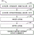
Fig. 5 shows a flow chart 500 according to an embodiment of the present disclosure. Method 500 may be implemented at any suitable device. For illustrative purposes only, the method 500 is described as being implemented at the network device 120.
At block 510, the network device 120 transmits a first signal in a first link having a first CFO value. For example, the network device 120 may transmit a synchronization signal, such as a primary synchronization signal and/or a secondary synchronization signal.
At block 520, network device 120 receives a second signal in a second link from terminal device 110-1 to network device 120. In some embodiments, the network device 120 may receive msg.1 from the terminal device 110-1. The network device 120 may receive the second signal on a carrier compensated with the second CFO value. For example, the center frequency of the carrier may be F 1 And the second CFO value may be 2*f 1 The second signal may be at a frequency F 1 +2*f 1 And (5) receiving. In other embodiments, the second signal may be at frequency F 1 -2*f 1 And (5) receiving.
In some embodiments, the second signal in the second link may instruct network device 120 to employ inter-carrier interference (ICI) cancellation. For example, msg.1 may include one bit of information indicating that ICI cancellation is employed. Network device 120 may not use ICI cancellation within a tolerance.
In some embodiments, at block 530, network device 120 may determine a third CFO value in the first link based on the transmission. For example, if the terminal device 110-1 transmits msg.1 to the network device 120, the network device 120 may estimate the third CFO value based on an attribute of msg.1 (e.g., a sequence of msg.1). The network device 120 may obtain a second CFO value in a second link.
In an example embodiment, at block 540, the network device 120 may adjust the third CFO value based on the acquired second CFO value in the second link. The uplink frequency of terminal device 110 may be aligned at network device 120. In this way, OFDMA orthogonality may be maintained by compensating for the first link doppler shift and the second link doppler shift.
In some embodiments, at block 550, network device 120 may send a third signal to terminal device 110-1 in the first link. The third signal may indicate that a third CFO value has been adjusted. For example, the network device 120 may send msg.2 to the terminal device 110-1. Msg.2 may include one or more bits for indicating that the third CFO value has been adjusted.
In some embodiments, network device 120 may receive the fourth signal in the second link on another carrier compensated with the fourth CFO value. For example, the center frequency of another carrier may be F 2 And the fourth CFO value may be 2*f 2 The fourth signal may be at frequency F 2 +2*f 2 And (5) receiving. In other embodiments, the fourth signal may be at frequency F 2 -2*f 2 And (5) receiving.
In some embodiments, an apparatus (e.g., control network device 120) for performing method 400 may include respective components for performing corresponding steps in method 400. These components may be implemented in any suitable manner. For example, it may be implemented by circuitry or software modules.
In some embodiments, the apparatus comprises: determining, at a first device, a first Carrier Frequency Offset (CFO) value in a first link based on a first signal received from a second device; means for determining whether a first CFO value in a first link from a second device to a first device exceeds a threshold offset; means for determining a second CFO value in a second link from the first device to the second device based on the first CFO value in the first link in response to determining that the first CFO value in the first link exceeds the threshold offset, the second CFO value in the second link being greater than the first CFO value in the first link; and means for performing a transmission from the first device to the second device on a carrier compensated with a second CFO value in the second link.
In some embodiments, the means for determining a second CFO value in the second link comprises: means for determining that the second CFO value in the second link is twice the first CFO value in the first link.
In some embodiments, the means for performing the transmission from the first device to the second device comprises: means for transmitting a second signal in the second link, the second signal instructing the second device to perform inter-carrier interference cancellation.
In some embodiments, the means for performing the transmission from the first device to the second device comprises: means for performing transmission using inter-carrier interference cancellation.
In some embodiments, the apparatus further comprises: means for receiving a third signal in the first link from the second device, the third signal in the first link indicating a third CFO value in the first link, the third CFO value being adjusted based on the second CFO value in the second link; means for determining a fourth CFO value in the second link based on the third CFO value in the first link, the fourth CFO value in the second link being greater than the third CFO value in the first link; and means for transmitting a fourth signal to the second device on a further carrier compensated with a fourth CFO value in the first link.
In some embodiments, the first device is a terminal device, the second device is a network device, the first link is a downlink, and the second link is an uplink.
In some embodiments, an apparatus (e.g., network device 120) for performing method 500 may include respective components for performing corresponding steps in method 500. These components may be implemented in any suitable manner. For example, it may be implemented by circuitry or software modules.
In some embodiments, the apparatus comprises: means for transmitting a first signal to a first device in a first link from the second device to the first device, the first link having a first Carrier Frequency Offset (CFO) value; and means for receiving a second signal from the first device in a second link on a carrier compensated with a second CFO value in response to the first CFO value in the first link exceeding a threshold offset, the second CFO value in the second link being greater than the first CFO value in the first link.
In some embodiments, the second CFO value in the second link is twice the first CFO value in the first link.
In some embodiments, the means for receiving the second signal from the first device comprises: means for receiving a second signal, the second signal instructing the second device to perform inter-carrier interference cancellation.
In some embodiments, the apparatus further comprises: means for determining a third CFO value in the first link based on the received second signal; and means for adjusting a third CFO value in the first link based on the second CFO value in the second link.
In some embodiments, the apparatus further comprises: means for transmitting a third signal in the first link to the first device, the third signal indicating a third CFO value in the first link; and means for receiving a fourth signal from the first device in the second link on a further carrier compensated with a fourth CFO value in the second link.
In some embodiments, the first device is a terminal device, the second device is a network device, the first link is a downlink, and the second link is an uplink.
Fig. 6 is a simplified block diagram of a device 600 suitable for implementing embodiments of the present disclosure. Device 600 may be provided to implement a communication device, such as network device 120 or terminal device 110 shown in fig. 1. As shown, device 600 includes one or more processors 610, one or more memories 620 coupled to processors 610, and one or more communication modules (e.g., a transmitter and/or receiver (TX/RX)) 640 coupled to processors 610.
The communication module 640 is used for two-way communication. The communication module 640 has at least one antenna to facilitate communication. The communication interface may represent any interface required to communicate with other network elements.
The processor 610 may be of any type suitable to the local technology network and may include, as non-limiting examples, one or more of the following: general purpose computers, special purpose computers, microprocessors, digital Signal Processors (DSPs), and processors based on a multi-core processor architecture. The device 600 may have multiple processors, such as an application specific integrated circuit chip that is slaved in time to a clock that is synchronized to the master processor.
Memory 620 may include one or more non-volatile memories and one or more volatile memories. Examples of non-volatile memory include, but are not limited to, read-only memory (ROM) 624, electrically programmable read-only memory (EPROM), flash memory, hard disks, compact Disks (CD), digital Video Disks (DVD), and other magnetic and/or optical storage devices. Examples of volatile memory include, but are not limited to, random Access Memory (RAM) 622 and other volatile memory that does not last for the duration of the power outage.
The computer program 630 includes computer-executable instructions that are executed by the associated processor 610. Program 630 may be stored in ROM 624. Processor 610 may perform any suitable actions and processes by loading program 630 into RAM 622.
Embodiments of the present disclosure may be implemented by program 630 such that device 600 may perform any of the processes of the present disclosure as discussed with reference to fig. 2-5. Embodiments of the present disclosure may also be implemented in hardware or a combination of software and hardware.
In some embodiments, program 630 may be tangibly embodied in a computer-readable medium that may be included in device 600 (such as in memory 620) or other storage device accessible to device 600. Device 600 may load program 630 from a computer readable medium into RAM 622 for execution. The computer readable medium may include any type of tangible, non-volatile memory, such as ROM, EPROM, flash memory, hard disk, CD, DVD, etc. Fig. 7 shows an example of a computer readable medium 700 in the form of a CD or DVD. The computer readable medium has a program 630 stored thereon.
In general, the various embodiments of the disclosure may be implemented in hardware or special purpose circuits, software, logic or any combination thereof. Some aspects may be implemented in hardware, while other aspects may be implemented in firmware or software which may be executed by a controller, microprocessor or other computing device. While various aspects of the embodiments of the disclosure are illustrated and described as block diagrams, flow charts, or using some other pictorial representation, it is well understood that the blocks, apparatus, systems, techniques or methods described herein may be implemented in hardware, software, firmware, special purpose circuits or logic, general purpose hardware or controller or other computing devices, or some combination thereof.
The present disclosure also provides at least one computer program product tangibly stored on a non-transitory computer-readable storage medium. The computer program product includes computer-executable instructions, such as those included in program modules, that are executed in a device on a target real or virtual processor to perform the methods 400 and 600 described above with reference to fig. 2-5. Generally, program modules include routines, programs, libraries, objects, classes, components, data types, etc. that perform particular tasks or implement particular abstract data types. The functionality of the program modules may be combined or split between program modules as desired in various embodiments. Machine-executable instructions for program modules may be executed within local or distributed devices. In distributed devices, program modules may be located in both local and remote memory storage media.
Program code for carrying out the methods of the present disclosure may be written in any combination of one or more programming languages. These program code may be provided to a processor or controller of a general purpose computer, special purpose computer, or other programmable data processing apparatus such that the program code, when executed by the processor or controller, causes the functions/operations specified in the flowchart and/or block diagram to be implemented. The program code may execute entirely on the machine, partly on the machine, as a stand-alone software package, partly on the machine and partly on a remote machine or entirely on the remote machine or server.
In the context of this disclosure, computer program code or related data may be carried by any suitable carrier to enable an apparatus, device, or processor to perform the various processes and operations described above. Examples of carriers include signals, computer readable media, and the like.
The computer readable medium may be a computer readable signal medium or a computer readable storage medium. The computer readable medium may include, but is not limited to, electronic, magnetic, optical, electromagnetic, infrared, or semiconductor systems, apparatus or devices, or any suitable combination thereof. More specific examples of a computer-readable storage medium include an electrical connection having one or more wires, a portable computer diskette, a hard disk, a Random Access Memory (RAM), a read-only memory (ROM), an erasable programmable read-only memory (EPROM or flash memory), an optical fiber, a portable compact disc read-only memory (CD-ROM), an optical storage device, a magnetic storage device, or any suitable combination thereof.
Moreover, although operations are depicted in a particular order, this should not be understood as requiring that such operations be performed in the particular order shown or in sequential order, or that all illustrated operations be performed, to achieve desirable results. In some cases, multitasking and parallel processing may be advantageous. Also, while the above discussion contains several specific implementation details, these should not be construed as limitations on the scope of the disclosure, but rather as descriptions of features specific to particular embodiments. Certain features that are described in the context of separate embodiments can also be implemented in combination in a single embodiment. Conversely, various features that are described in the context of a single embodiment can also be implemented in multiple embodiments separately or in any suitable subcombination.
Although the disclosure has been described in language specific to structural features and/or methodological acts, it is to be understood that the disclosure defined in the appended claims is not necessarily limited to the specific features or acts described above. Rather, the specific features and acts described above are disclosed as example forms of implementing the claims.