CN113785253A - Information processing apparatus, information processing method, and program - Google Patents
Information processing apparatus, information processing method, and program Download PDFInfo
- Publication number
- CN113785253A CN113785253A CN202080032997.2A CN202080032997A CN113785253A CN 113785253 A CN113785253 A CN 113785253A CN 202080032997 A CN202080032997 A CN 202080032997A CN 113785253 A CN113785253 A CN 113785253A
- Authority
- CN
- China
- Prior art keywords
- information
- unit
- map
- priority
- processing apparatus
- Prior art date
- Legal status (The legal status is an assumption and is not a legal conclusion. Google has not performed a legal analysis and makes no representation as to the accuracy of the status listed.)
- Granted
Links
Images


Classifications
-
- G—PHYSICS
- G06—COMPUTING OR CALCULATING; COUNTING
- G06V—IMAGE OR VIDEO RECOGNITION OR UNDERSTANDING
- G06V10/00—Arrangements for image or video recognition or understanding
- G06V10/70—Arrangements for image or video recognition or understanding using pattern recognition or machine learning
- G06V10/764—Arrangements for image or video recognition or understanding using pattern recognition or machine learning using classification, e.g. of video objects
-
- G—PHYSICS
- G05—CONTROLLING; REGULATING
- G05D—SYSTEMS FOR CONTROLLING OR REGULATING NON-ELECTRIC VARIABLES
- G05D1/00—Control of position, course, altitude or attitude of land, water, air or space vehicles, e.g. using automatic pilots
- G05D1/20—Control system inputs
- G05D1/24—Arrangements for determining position or orientation
- G05D1/242—Means based on the reflection of waves generated by the vehicle
-
- G—PHYSICS
- G05—CONTROLLING; REGULATING
- G05D—SYSTEMS FOR CONTROLLING OR REGULATING NON-ELECTRIC VARIABLES
- G05D1/00—Control of position, course, altitude or attitude of land, water, air or space vehicles, e.g. using automatic pilots
- G05D1/20—Control system inputs
- G05D1/24—Arrangements for determining position or orientation
- G05D1/246—Arrangements for determining position or orientation using environment maps, e.g. simultaneous localisation and mapping [SLAM]
- G05D1/2464—Arrangements for determining position or orientation using environment maps, e.g. simultaneous localisation and mapping [SLAM] using an occupancy grid
-
- G—PHYSICS
- G06—COMPUTING OR CALCULATING; COUNTING
- G06F—ELECTRIC DIGITAL DATA PROCESSING
- G06F18/00—Pattern recognition
- G06F18/20—Analysing
- G06F18/22—Matching criteria, e.g. proximity measures
-
- G—PHYSICS
- G06—COMPUTING OR CALCULATING; COUNTING
- G06N—COMPUTING ARRANGEMENTS BASED ON SPECIFIC COMPUTATIONAL MODELS
- G06N3/00—Computing arrangements based on biological models
- G06N3/02—Neural networks
- G06N3/04—Architecture, e.g. interconnection topology
- G06N3/0464—Convolutional networks [CNN, ConvNet]
-
- G—PHYSICS
- G06—COMPUTING OR CALCULATING; COUNTING
- G06N—COMPUTING ARRANGEMENTS BASED ON SPECIFIC COMPUTATIONAL MODELS
- G06N3/00—Computing arrangements based on biological models
- G06N3/02—Neural networks
- G06N3/08—Learning methods
-
- G—PHYSICS
- G06—COMPUTING OR CALCULATING; COUNTING
- G06N—COMPUTING ARRANGEMENTS BASED ON SPECIFIC COMPUTATIONAL MODELS
- G06N3/00—Computing arrangements based on biological models
- G06N3/02—Neural networks
- G06N3/08—Learning methods
- G06N3/09—Supervised learning
-
- G—PHYSICS
- G06—COMPUTING OR CALCULATING; COUNTING
- G06V—IMAGE OR VIDEO RECOGNITION OR UNDERSTANDING
- G06V10/00—Arrangements for image or video recognition or understanding
- G06V10/20—Image preprocessing
- G06V10/26—Segmentation of patterns in the image field; Cutting or merging of image elements to establish the pattern region, e.g. clustering-based techniques; Detection of occlusion
-
- G—PHYSICS
- G06—COMPUTING OR CALCULATING; COUNTING
- G06V—IMAGE OR VIDEO RECOGNITION OR UNDERSTANDING
- G06V20/00—Scenes; Scene-specific elements
- G06V20/10—Terrestrial scenes
- G06V20/17—Terrestrial scenes taken from planes or by drones
-
- G—PHYSICS
- G06—COMPUTING OR CALCULATING; COUNTING
- G06V—IMAGE OR VIDEO RECOGNITION OR UNDERSTANDING
- G06V20/00—Scenes; Scene-specific elements
- G06V20/50—Context or environment of the image
- G06V20/56—Context or environment of the image exterior to a vehicle by using sensors mounted on the vehicle
- G06V20/58—Recognition of moving objects or obstacles, e.g. vehicles or pedestrians; Recognition of traffic objects, e.g. traffic signs, traffic lights or roads
-
- G—PHYSICS
- G06—COMPUTING OR CALCULATING; COUNTING
- G06V—IMAGE OR VIDEO RECOGNITION OR UNDERSTANDING
- G06V30/00—Character recognition; Recognising digital ink; Document-oriented image-based pattern recognition
- G06V30/10—Character recognition
- G06V30/19—Recognition using electronic means
- G06V30/191—Design or setup of recognition systems or techniques; Extraction of features in feature space; Clustering techniques; Blind source separation
- G06V30/19153—Design or setup of recognition systems or techniques; Extraction of features in feature space; Clustering techniques; Blind source separation using rules for classification or partitioning the feature space
-
- G—PHYSICS
- G01—MEASURING; TESTING
- G01S—RADIO DIRECTION-FINDING; RADIO NAVIGATION; DETERMINING DISTANCE OR VELOCITY BY USE OF RADIO WAVES; LOCATING OR PRESENCE-DETECTING BY USE OF THE REFLECTION OR RERADIATION OF RADIO WAVES; ANALOGOUS ARRANGEMENTS USING OTHER WAVES
- G01S17/00—Systems using the reflection or reradiation of electromagnetic waves other than radio waves, e.g. lidar systems
- G01S17/88—Lidar systems specially adapted for specific applications
- G01S17/89—Lidar systems specially adapted for specific applications for mapping or imaging
-
- G—PHYSICS
- G01—MEASURING; TESTING
- G01S—RADIO DIRECTION-FINDING; RADIO NAVIGATION; DETERMINING DISTANCE OR VELOCITY BY USE OF RADIO WAVES; LOCATING OR PRESENCE-DETECTING BY USE OF THE REFLECTION OR RERADIATION OF RADIO WAVES; ANALOGOUS ARRANGEMENTS USING OTHER WAVES
- G01S7/00—Details of systems according to groups G01S13/00, G01S15/00, G01S17/00
- G01S7/48—Details of systems according to groups G01S13/00, G01S15/00, G01S17/00 of systems according to group G01S17/00
- G01S7/4802—Details of systems according to groups G01S13/00, G01S15/00, G01S17/00 of systems according to group G01S17/00 using analysis of echo signal for target characterisation; Target signature; Target cross-section
-
- G—PHYSICS
- G05—CONTROLLING; REGULATING
- G05D—SYSTEMS FOR CONTROLLING OR REGULATING NON-ELECTRIC VARIABLES
- G05D2105/00—Specific applications of the controlled vehicles
- G05D2105/20—Specific applications of the controlled vehicles for transportation
- G05D2105/28—Specific applications of the controlled vehicles for transportation of freight
-
- G—PHYSICS
- G05—CONTROLLING; REGULATING
- G05D—SYSTEMS FOR CONTROLLING OR REGULATING NON-ELECTRIC VARIABLES
- G05D2107/00—Specific environments of the controlled vehicles
- G05D2107/10—Outdoor regulated spaces
- G05D2107/13—Spaces reserved for vehicle traffic, e.g. roads, regulated airspace or regulated waters
-
- G—PHYSICS
- G05—CONTROLLING; REGULATING
- G05D—SYSTEMS FOR CONTROLLING OR REGULATING NON-ELECTRIC VARIABLES
- G05D2107/00—Specific environments of the controlled vehicles
- G05D2107/70—Industrial sites, e.g. warehouses or factories
-
- G—PHYSICS
- G05—CONTROLLING; REGULATING
- G05D—SYSTEMS FOR CONTROLLING OR REGULATING NON-ELECTRIC VARIABLES
- G05D2109/00—Types of controlled vehicles
- G05D2109/10—Land vehicles
-
- G—PHYSICS
- G05—CONTROLLING; REGULATING
- G05D—SYSTEMS FOR CONTROLLING OR REGULATING NON-ELECTRIC VARIABLES
- G05D2111/00—Details of signals used for control of position, course, altitude or attitude of land, water, air or space vehicles
- G05D2111/10—Optical signals
- G05D2111/17—Coherent light, e.g. laser signals
Landscapes
- Engineering & Computer Science (AREA)
- Theoretical Computer Science (AREA)
- Physics & Mathematics (AREA)
- General Physics & Mathematics (AREA)
- Multimedia (AREA)
- Artificial Intelligence (AREA)
- Evolutionary Computation (AREA)
- Computing Systems (AREA)
- Software Systems (AREA)
- General Health & Medical Sciences (AREA)
- Health & Medical Sciences (AREA)
- Data Mining & Analysis (AREA)
- Computer Vision & Pattern Recognition (AREA)
- General Engineering & Computer Science (AREA)
- Life Sciences & Earth Sciences (AREA)
- Biomedical Technology (AREA)
- Biophysics (AREA)
- Molecular Biology (AREA)
- Computational Linguistics (AREA)
- Mathematical Physics (AREA)
- Remote Sensing (AREA)
- Databases & Information Systems (AREA)
- Medical Informatics (AREA)
- Aviation & Aerospace Engineering (AREA)
- Automation & Control Theory (AREA)
- Radar, Positioning & Navigation (AREA)
- Evolutionary Biology (AREA)
- Bioinformatics & Cheminformatics (AREA)
- Bioinformatics & Computational Biology (AREA)
- Traffic Control Systems (AREA)
Abstract
An information processing apparatus according to an embodiment of the present technology is provided with a classification unit and a generation unit. The classification unit classifies the object detected in the space based on a prescribed criterion. The generation unit sets a priority to the object based on a classification result performed by the classification unit, and generates position-related information related to a position in the space based on the set priority. Using the position-related information makes it possible to improve the accuracy of autonomous travel control. Thereby, the accuracy of autonomous travel control can be improved.
Description
Technical Field
The present technology relates to an information processing device, an information processing method, and a program suitable for controlling a mobile object capable of autonomous movement.
Background
Patent document 1 describes an environment mapping system to be mounted on a moving object having an autonomous driving function. In such an environment mapping system, position information of each position in space and a state quantity of the position (probability of an object existing at the position) are calculated. The position information, the representative value of the state quantity, and the variability of the state quantity are associated with each other to generate map information. This makes it possible to more accurately represent the situation in space (for example, paragraphs [0021] to [0033] and fig. 7 of the specification of patent document 1).
CITATION LIST
Patent document
Patent document 1: japanese patent application laid-open No.2017-
Disclosure of Invention
Technical problem
As described above, there is a need for a technique capable of performing autonomous movement control of a moving object with high accuracy.
In view of the above circumstances, an object of the present technology is to provide an information processing apparatus, an information processing method, and a program that can improve the accuracy of autonomous movement control.
Solution to the problem
In order to achieve the above object, an information processing apparatus according to an embodiment of the present technology includes a classification unit and a generation unit.
The classification unit classifies the object detected in the space based on a predetermined criterion.
The generation unit sets a priority to the object based on the classification result of the classification unit, and generates the position-related information on the position in the space based on the set priority.
In the information processing apparatus, objects detected in a space are classified based on a predetermined criterion, and a priority is set based on the classification result. Based on the set priority, position-related information about a position in the space is generated. Using such position-related information makes it possible to improve the accuracy of autonomous movement control.
The classification unit may classify the object based on a likelihood of movement of the object.
The classification unit may classify the object based on date and time information.
The generation unit may set the priority based on the date and time information.
The classification unit may classify the object as a moving object, a quasi-stationary object, or a stationary object.
The generation unit may set a first priority to the object classified as the moving object, set a second priority higher than the first priority to the object classified as the quasi-stationary object, and set a third priority higher than the second priority to the object classified as the stationary object.
The classification unit may classify the object based on detection information detected by a sensor possessed by a moving object moving in the space. In this case, the generation unit may generate position information regarding the position and posture of the moving object in the space as the position-related information.
The generation unit may generate the position information of the moving object by collating the detection information with the map information on the space based on the priority.
The generation unit may select collation subject information to be collated with the map information from the detection information based on the priority.
The generation unit may generate map information on the space as the position-related information.
The map information may include the positions of objects detected in the space and priorities set for the objects.
The map information may include at least one of an occupancy grid map or a group of image feature points each including position information.
The map information may be an occupancy grid map. In this case, the generation unit may set a priority to each mesh occupying the mesh map based on the priority.
The generation unit may set divided areas for dividing the space into the plurality of areas based on the classification result, and generate the map information for each of the divided areas.
The generation unit may set the divided regions based on the position of the object detected in the space and the classification result of the object.
The generation unit may update the map information corresponding to each divided area based on movement of the object from each divided area.
The generation unit may generate update information for updating the map information generated for each divided area based on the classification result of the object in each divided area.
The update information may include at least one of a necessity of the update, a timing of the update, or a frequency of the update.
An information processing method according to an embodiment of the present technology is an information processing method executed by a computer system, the method including: classifying the object detected in the space based on a predetermined criterion; and setting a priority to the object based on the classified result of the classification, and generating position-related information about a position in space based on the set priority.
A program according to an embodiment of the present technology causes a computer system to execute the steps of: classifying the object detected in the space based on a predetermined criterion; and setting a priority to the object based on the classified result of the classification, and generating position-related information about a position in space based on the set priority.
Drawings
Fig. 1 is a block diagram showing an example of a schematic functional configuration of a mobile object control system for controlling autonomous movement of a mobile object according to an embodiment of the present technology.
Fig. 2 is a flowchart for describing an outline of the present technology.
Fig. 3 is a schematic diagram for describing an example of detection of an object in space.
FIG. 4 is a schematic diagram of an example of generation of a learned model for describing semantic segmentation.
Fig. 5 is a table showing an example of classification of objects.
Fig. 6 is a table for describing dead reckoning and star reckoning.
Fig. 7 is a diagram showing a configuration example of blocks operated when self position estimation is performed.
Fig. 8 is a flowchart showing an example of self-position estimation by star estimation.
Fig. 9 is a schematic diagram for describing an example of a pre-map.
Fig. 10 is a diagram showing a configuration example of blocks operated when map information is generated.
Fig. 11 is a flowchart showing an example of generation of map information.
Fig. 12 is a schematic diagram for describing divided map information.
Fig. 13 is a schematic diagram showing a configuration example of blocks operated when divided map information is generated.
Fig. 14 is a flowchart showing an example of setting divided areas.
Fig. 15 is a flowchart showing an example of updating divided map information.
Fig. 16 is a schematic block diagram showing a combination of self-position estimation and map information generation.
Detailed Description
Hereinafter, embodiments of the present technology will be described with reference to the drawings.
[ configuration example of Mobile object control System ]
Fig. 1 is a block diagram showing an example of a schematic functional configuration of a mobile object control system 100 for controlling autonomous movement of a mobile object according to an embodiment of the present technology. Note that the moving object control system 100 of fig. 1 is an example of a moving object control system for controlling a moving object including a robot to which the present technology can be applied, but it may also be used as a system for controlling other moving objects such as an airplane, a ship, and a multi-rotor helicopter (drone). In addition, the robot may be a wheeled robot or an autonomous driving vehicle on which a person can ride, or may be a multi-legged walking robot. Of course, it may also be applied to a robot including a leg portion having a hinge structure as a driving portion.
The moving object control system 100 includes an input unit 101, a data acquisition unit 102, a communication unit 103, a moving object internal device 104, an output control unit 105, an output unit 106, a power train control unit 107, a power train system 108, a storage unit 109, and an autonomous movement control unit 110. The input unit 101, the data acquisition unit 102, the communication unit 103, the output control unit 105, the power train control unit 107, the storage unit 109, and the autonomous movement control unit 110 are connected to each other via a communication network 111. For example, the communication network 111 includes a communication network or a bus conforming to any standard such as a Controller Area Network (CAN), a Local Interconnect Network (LIN), a Local Area Network (LAN) such as IEEE802.3, or FlexRay (registered trademark), or a unique communication method not standardized, or the like. Note that the units of the mobile object control system 100 may be directly connected to each other without using the communication network 111.
Note that, hereinafter, in the case where the units of the mobile object control system 100 communicate with each other via the communication network 111, description of the communication network 111 will be omitted. For example, in the case where the input unit 101 and the autonomous mobile control unit 110 communicate with each other via the communication network 111, a simple description will be given of instructing the input unit 101 and the autonomous mobile control unit 110 to communicate with each other.
The input unit 101 includes a device for inputting various data, instructions, and the like. For example, the input unit 101 includes an operation device such as a touch panel, a button, a microphone, a switch, or a lever, an operation device capable of inputting information by sound, a gesture, or the like other than manual operation, and the like. Alternatively, for example, the input unit 101 may be an externally connected device (such as a remote control device using infrared rays or other radio waves), or a mobile device or wearable device compatible with the operation of the mobile object control system 100. The input unit 101 generates an input signal based on input data, instructions, and the like, and supplies the generated input signal to the respective units of the moving object control system 100.
The data acquisition unit 102 includes various sensors and the like for acquiring data to be used in the processing performed by the moving object control system 100, and supplies the acquired data to the respective units of the moving object control system 100. For example, the data acquisition unit 102 includes various sensors for detecting the state of a moving object and the like to constitute a sensor group 112.
Specifically, for example, the data acquisition unit 102 includes a geomagnetic sensor, a gyro sensor, an acceleration sensor, an Inertia Measurement Unit (IMU) for detecting a direction, and sensors for detecting an operation amount of an acceleration input such as an accelerator, an operation amount of a deceleration input, an operation amount of a direction instruction input, the number of revolutions, and input-output energy and fuel amount of a driving apparatus such as an engine or a motor, a torque amount of the engine or the motor, or the like, a rotation speed or torque at a wheel or a joint, or the like.
In addition, for example, the data acquisition unit 102 includes various sensors for detecting information on the outside of the moving object. Specifically, for example, the data acquisition unit 102 includes an imaging device such as a time-of-flight (ToF) camera, a stereo camera, a monocular camera, an infrared camera, a polarization camera, or other cameras. In addition, for example, the data acquisition unit 102 includes an environmental sensor for detecting weather, meteorological phenomena, or the like, and a surrounding information detection sensor for detecting objects around a moving object. For example, the environmental sensor includes a temperature sensor, a humidity sensor, a raindrop sensor, a fog sensor, a sunlight sensor, a snow sensor, and the like. The surrounding information detection sensor includes a laser ranging sensor, a contact sensor, an ultrasonic sensor, a radar, a LiDAR (light detection and ranging, laser imaging detection and ranging) sensor, a sonar, and the like.
Further, for example, the data acquisition unit 102 includes various sensors for detecting the current position of the moving object. Specifically, for example, the data acquisition unit 102 includes a Global Navigation Satellite System (GNSS) receiver that receives GNSS signals from GNSS satellites.
In this embodiment, various detection results detected by the sensor group 112 correspond to detection information detected by sensors included in the moving object. The detection information includes not only detection values detected by the sensor group 112 but also various types of data and the like that can be calculated from the detection values.
The communication unit 103 communicates with the mobile object internal device 104, various devices outside the mobile object, a server, a base station, and the like, transmits data supplied from the respective units of the mobile object control system 100, and supplies the received data to the respective units of the mobile object control system 100. Note that the communication protocol supported by the communication unit 103 is not particularly limited. In addition, the communication unit 103 may also support multiple types of communication protocols.
For example, the communication unit 103 establishes a wireless connection with the moving object internal device 104 by using wireless LAN, bluetooth (registered trademark), Near Field Communication (NFC), wireless usb (wusb), or the like. In addition, for example, the communication unit 103 establishes a wired connection with the moving object internal device 104 by using a Universal Serial Bus (USB), a high-definition multimedia interface (HDMI), a mobile high-definition link (MHL), or the like via a connection terminal (and a cable if necessary) (not shown).
Further, for example, the communication unit 103 communicates with equipment (e.g., an application server or a control server) existing on an external network (e.g., the internet, a cloud network, or a company-specific network) via a base station or an access point. In addition, for example, the communication unit 103 communicates with a terminal (e.g., a terminal of a pedestrian or a shop, or a Machine Type Communication (MTC) terminal) existing in the vicinity of the moving object by using a peer-to-peer (P2P) technique. Further, for example, if the moving object is a vehicle, the communication unit 103 performs V2X communication such as vehicle-to-vehicle communication, vehicle-to-infrastructure communication, vehicle-to-home communication between the moving object and home, or vehicle-to-pedestrian communication. In addition, for example, the communication unit 103 includes a beacon receiver that receives radio waves or electromagnetic waves transmitted from a radio station or the like and acquires information such as the current position or necessary time.
The moving object internal device 104 includes, for example, mobile equipment or wearable equipment owned by the user, information equipment carried or attached to the moving object, a navigation apparatus that searches for a route to any destination, and the like.
The output control unit 105 controls output of various information to the outside of the moving object. For example, the output control unit 105 generates an output signal including at least one of visual information (such as image data) or audio information (such as sound data), supplies the output signal to the output unit 106, and thereby controls output of the visual information and the audio information from the output unit 106. Specifically, for example, the output control unit 105 combines a plurality of pieces of image data captured by different imaging devices included in the data acquisition unit 102, generates a bird's-eye view image, a panoramic image, and the like, and supplies an output signal including the generated image to the output unit 106. In addition, for example, the output control unit 105 generates sound data including a warning sound, a warning message, and the like for danger such as collision, contact, or entrance into a dangerous zone (zone), and supplies an output signal including the generated sound data to the output unit 106.
The output unit 106 includes a device capable of outputting visual information or audio information to the outside of the moving object. For example, the output unit 106 includes a display device, an instrument panel, an audio speaker, an earphone, a wearable device (such as a glasses-type display) worn by a user, or the like, a projector, a lamp, or the like. The display device included in the output unit 106 may be, for example, a device that displays visual information within the field of view of the driver, such as a head-up display, a transparent display, or a device having an Augmented Reality (AR) function, in addition to a device including a normal display. Note that the output control unit 105 and the output unit 106 are not essential for the autonomous moving process, and therefore they may be omitted as needed.
The power train control unit 107 generates various control signals, supplies them to the power train system 108, and thereby controls the power train system 108. In addition, the power train control unit 107 supplies a control signal to structural elements other than the power train system 108 and notifies them of the control state of the power train system 108 and the like as necessary.
The powertrain system 108 includes various devices associated with the powertrain of the mobile object. For example, the power train system 108 includes a servo motor provided in each joint of four legs and capable of specifying an angle or torque, a motion controller that decomposes and replaces the movement of the robot itself with the movement of the four legs, and a feedback controller by a sensor of each motor or a sensor of a sole surface.
In another example, the powertrain system 108 includes motors with four or six upward thrusters, and a motion controller that breaks up and replaces the movement of the robot itself with the amount of rotation of each motor.
Further, in another example, the powertrain system 108 includes: a driving force generating device for generating a driving force of an internal combustion engine, a driving motor, etc., a driving force transmitting mechanism for transmitting the driving force to wheels, a steering mechanism for adjusting a steering angle, a braking device for generating a braking force, an anti-lock brake system (ABS), an Electronic Stability Control (ESC) system, an electric power steering device, etc.
The storage unit 109 includes, for example, a Read Only Memory (ROM), a Random Access Memory (RAM), a magnetic storage device such as a Hard Disk Drive (HDD) or the like, a semiconductor storage device, an optical storage device, a magneto-optical storage device, or the like. The storage unit 109 stores various programs, data, and the like used by the respective units of the moving object control system 100. For example, the storage unit 109 stores map data (map information) such as a three-dimensional high-precision map, a global map, and a local map. The three-dimensional high-precision map is a dynamic map and the like. The accuracy of the global map is lower than that of the high-accuracy map, but the coverage range is wider than that of the high-accuracy map. The local map includes information about the surroundings of the moving object.
The autonomous movement control unit 110 performs control of autonomous movement, such as autonomous driving or driving assistance. Specifically, for example, the autonomous movement control unit 110 performs cooperative control intended to implement functions of collision avoidance or vibration reduction of the moving object, following movement based on a following distance, moving object speed maintenance movement, moving object collision warning, and the like. In addition, for example, the autonomous movement control unit 110 may also perform cooperative control with the purpose of autonomous movement such that the mobile object autonomously travels without depending on an operation of the user or the like.
The autonomous mobile control unit 110 serves as an embodiment of an information processing apparatus according to the present technology and includes hardware required for a computer, such as a CPU, a RAM, and a ROM. The information processing method according to the present technology is executed when the CPU loads a program according to the present technology, which is stored in advance in the ROM, to the RAM and executes the program.
The program is installed on the autonomous movement control unit 110 via various recording media, for example. Alternatively, the installation of the program may be performed via the internet or the like.
Note that the type and the like of the recording medium on which the program is recorded are not limited, and any computer-readable recording medium may be used. For example, any recording medium for recording data in a non-transitory manner may be used.
The specific configuration of the autonomous mobile control unit 110 is not limited. For example, a Programmable Logic Device (PLD) such as a Field Programmable Gate Array (FPGA) or other device such as an Application Specific Integrated Circuit (ASIC) may be used.
As shown in fig. 1, the autonomous movement control unit 110 includes a detection unit 131, a self-position estimation unit 132, a situation analysis unit 133, a planning unit 134, and a behavior control unit 135. Among them, the detection unit 131, the self-position estimation unit 132, and the situation analysis unit 133 constitute the recognition processing unit 121. The planning means 134 constitutes the operation planning processing means 122. Further, the behavior control unit 135 constitutes the motion control processing unit 123.
The detection unit 131 detects various information required to control the autonomous movement of the moving object. The detection unit 131 includes a moving object external information detection unit 141, a moving object internal information detection unit 142, and a moving object state detection unit 143.
The moving object external information detection unit 141 performs a process of detecting information on the outside of the moving object based on data or signals from the respective units of the moving object control system 100. For example, the moving object external information detection unit 141 performs detection processing, recognition processing, tracking processing of objects around the moving object, and processing of detecting a distance to the object. Examples of the detection target object include a moving object, a person, an obstacle, a building, a road, a traffic light, a traffic sign, a road sign, and the like. In addition, for example, the moving object external information detection unit 141 performs a process of detecting the surrounding environment of the moving object. Examples of the surrounding environment of the detection object include, for example, weather, temperature, humidity, brightness, road surface condition, and the like. The mobile object external information detection unit 141 supplies data indicating the result of the detection processing to the own position estimation unit 132, the map analysis unit 151 and the situation recognition unit 152 of the situation analysis unit 133, the behavior control unit 135, and the like.
The moving object interior information detection unit 142 performs a process of detecting information on the interior of the moving object based on data or signals from the respective units of the moving object control system 100. For example, if there is a driver driving a moving object, the moving object internal information detection unit 142 performs authentication processing and recognition processing of the driver, detection processing of the state of the driver, detection processing of passengers, detection processing of the internal environment of the moving object, and the like. Examples of the state of the driver as the detection target include a health condition, a degree of consciousness, a degree of concentration, a degree of fatigue, a line-of-sight direction, and the like. Examples of the internal environment of the moving object as the detection object include temperature, humidity, brightness, smell, and the like. The moving object internal information detection unit 142 supplies data indicating the result of the detection processing to the situation recognition unit 152, the behavior control unit 135, and the like of the situation analysis unit 133.
The moving object state detection unit 143 performs a process of detecting the state of the moving object based on data or signals from the respective units of the moving object control system 100. Examples of the state of the moving object as the detection target include speed, acceleration, steering angle, presence or absence of abnormality, contents of abnormality, driving operation state, position and inclination of a power seat, state of a door lock, state of equipment mounted on other moving objects, and the like. The moving object state detection unit 143 supplies data indicating the result of the detection processing to the situation recognition unit 152, the behavior control unit 135, and the like of the situation analysis unit 133.
The self position estimation unit 132 performs processing of estimating the position, orientation, and the like of the mobile object based on data or signals from the respective units of the mobile object control system 100, such as the situation recognition unit 152 of the mobile object external information detection unit 141 and the situation analysis unit 133. In addition, the self-position estimating unit 132 generates a local map (hereinafter, referred to as a self-position estimation map) for estimating the self-position, as necessary. For example, the self position estimation map may be a high-precision map using a technique such as simultaneous localization and mapping (SLAM). The self-position estimation unit 132 supplies data indicating the result of the estimation processing to the map analysis unit 151 and the situation recognition unit 152 of the situation analysis unit 133, and the like. Further, the self-position estimating unit 132 causes the storage unit 109 to store the self-position estimation map.
Further, the self-position estimating unit 132 accumulates time-series information supplied in time series in a database based on the detection result (detection information) supplied from the sensor group 112, estimates the self-position based on the accumulated time-series information, and outputs it as the time-series information self-position. In addition, the self-position estimating unit 132 estimates the self-position based on the current detection result supplied from the sensor group 112, and outputs it as the current information self-position. Then, the self-position estimating unit 132 outputs the self-position estimation result by integrating or switching the time-series information self-position and the current-information self-position. Further, the self-position estimation unit 132 detects the posture of the moving object based on the detection results supplied from the sensor group 112. When a change in posture is detected and it is assumed that the self position changes greatly and the estimation accuracy of the self position of the time-series information decreases, the self position estimation unit 132 estimates the self position from only the current information self position. In addition, for example, if the mobile object is mounted on other mobile objects and moves, even if the posture change of the mobile object is not detected based on the detection result supplied from the sensor group 112, the self position greatly changes, so the self position estimation unit 132 assumes that the estimation accuracy of the time-series information self position is lowered, and estimates the self position only from the current information self position. For example, a case is conceivable in which the mobile object is a vehicle and is mounted on a car ferry to move. In this way, even if there is a posture change that cannot be predicted in advance and the self position changes greatly regardless of the influence of an external force, the self position is estimated only from the current information self position, so that the self position can be estimated with a predetermined accuracy.
The situation analysis unit 133 performs processing of analyzing the situation of the moving object and the situation around the moving object. The situation analyzing unit 133 includes a map analyzing unit 151, a situation recognizing unit 152, and a situation predicting unit 153.
The map analysis unit 151 performs a process of analyzing various maps stored in the storage unit 109, and constructs a map including information necessary for autonomous movement processing while using data or signals from respective units (such as the own position estimation unit 132 and the mobile object external information detection unit 141 as necessary) of the mobile object control system 100. The map analysis unit 151 supplies the constructed map to the situation recognition unit 152 and the situation prediction unit 153, and to the route planning unit 161, the action planning unit 162, the action planning unit 163, and the like of the planning unit 134.
The situation recognition unit 152 performs a process of recognizing the situation related to the mobile object based on data or signals from the respective units of the mobile object control system 100, such as the own position estimation unit 132, the mobile object external information detection unit 141, the mobile object internal information detection unit 142, the vehicle condition detection unit 143, and the map analysis unit 151. For example, the situation recognition unit 152 performs processing of recognizing the situation of the moving object, the situation around the moving object, the situation of the driver of the moving object, and the like. In addition, the situation recognition unit 152 generates a local map (hereinafter referred to as a situation recognition map) for recognizing the situation around the moving object, as necessary. For example, the situation recognition map may be an occupancy grid map, a road map (lane map), or a point cloud map.
Examples of the case of the moving object as the recognition target include a position, a posture, and a movement (such as a velocity, an acceleration, or a moving direction, for example) of the moving object, presence or absence of an abnormality, contents of the abnormality, and the like. Examples of the situation around the moving object as the recognition target include the type and position of a surrounding stationary object, the type, position, and movement (such as speed, acceleration, and moving direction, for example) of a surrounding moving object, the structure of a surrounding road, road surface conditions, ambient weather, temperature, humidity, brightness, and the like. Examples of the state of the driver as the recognition target include a health condition, a degree of consciousness, a degree of concentration, a degree of fatigue, a line of sight movement, a driving operation, and the like.
The situation recognizing unit 152 supplies data (including a situation recognition map as necessary) indicating the result of the recognition processing to the own position estimating unit 132, the situation predicting unit 153, and the like. Further, the situation recognition unit 152 causes the storage unit 109 to store the situation recognition map.
The situation prediction unit 153 performs a process of predicting a situation related to the moving object based on data or signals from respective units (such as the map analysis unit 151, the situation recognition unit 152, and the like) of the moving object control system 100. For example, the situation prediction unit 153 performs processing of predicting the situation of the mobile object, the situation around the mobile object, the situation of the driver, and the like.
Examples of the case of the moving object as the prediction target include the behavior of the moving object, the occurrence of an abnormality, a movable distance, and the like. Examples of the situation around the moving object as the prediction target include behavior of the moving object, a change in traffic light state, a change in the environment (such as weather) around the moving object, and the like. Examples of the situation of the driver as the prediction target include behavior, health condition, and the like of the driver.
The situation prediction unit 153 supplies data indicating the result of the prediction processing to the route planning unit 161, the action planning unit 162, the action planning unit 163, and the like of the planning unit 134, in addition to the data from the situation recognition unit 152.
The route planning unit 161 plans a route to a destination based on data or signals from the respective units of the mobile object control system 100, such as the map analysis unit 151 and the situation prediction unit 153. For example, the route planning unit 161 sets a route from the current position to a specified destination based on the global map. In addition, the route planning unit 161 appropriately changes the route based on situations such as people, obstacles, traffic congestion, accidents, traffic control, and construction, and the health condition of the driver, for example. The route planning unit 161 supplies data indicating a planned route to the action planning unit 162 and the like.
The action planning unit 162 plans the action of the mobile object to safely move in the route planned by the route planning unit 161 within the planned time period based on data or signals from the respective units (such as the map analysis unit 151 and the situation prediction unit 153) of the mobile object control system 100. For example, the action planning unit 162 plans start, stop, driving direction (e.g., forward, backward, left turn, right turn, change direction, etc.), moving speed, passing, and the like. The action planning unit 162 supplies data indicating actions planned for the mobile object to the action planning unit 163 and the like.
More specifically, the action planning unit 162 generates, as action plan candidates, candidates of an action plan (movement plan) in which the mobile object moves safely within the planned time for each route planned by the route planning unit 161. More specifically, the action planning unit 162 generates action planning candidates by, for example, an a-star algorithm (a star search algorithm) that divides the environment into meshes and optimizes the arrival determination and the weight of the route to generate an optimal path, a lane algorithm that sets the route according to the center line of the road, a Dijkstra' salgorithm algorithm that obtains the shortest route between two vertices on the graph, a rapid search random tree (RRT) algorithm that expands the path from its own position to an incrementally reachable position while appropriately pruning the path, and the like.
The action planning unit 163 plans the actions of the mobile object based on data or signals from the respective units (such as the map analysis unit 151 and the situation prediction unit 153) of the mobile object control system 100 to implement the actions planned by the action planning unit 162. For example, the behavior planning unit 163 plans acceleration, deceleration, movement routes, and the like. The behavior planning unit 163 supplies data indicating the planned behavior of the mobile object to the behavior control unit 135 and the like.
The behavior control unit 135 controls the behavior of the moving object.
More specifically, the behavior control unit 135 performs a process of detecting a collision, a contact, an entrance into an unsafe zone, or an emergency such as an abnormality of a driver or an abnormality of a moving object, based on the detection results obtained by the moving object external information detection unit 141, the moving object internal information detection unit 142, and the moving object state detection unit 143. In the case where the occurrence of an emergency is detected, the behavior control unit 135 plans the behavior of the mobile object, such as a quick stop or a quick turn, to avoid the emergency.
In addition, the behavior control unit 135 controls acceleration/deceleration to achieve the behavior of the mobile object planned by the behavior planning unit 163. For example, the behavior control unit 135 calculates a control target value of a driving force generation device or a brake device for achieving a planned acceleration, deceleration, or quick stop, and supplies a control instruction indicating the calculated control target value to the power train control unit 107.
The behavior control unit 135 controls the direction in which the behavior of the mobile object planned by the behavior planning unit 163 is implemented. For example, the behavior control unit 135 calculates a control target value of the steering mechanism for achieving the movement route or the quick turn planned by the behavior planning unit 163, and supplies a control instruction indicating the calculated control target value to the powertrain control unit 107.
[ summary of the present technology ]
Fig. 2 is a flowchart for describing an outline of the present technology.
Each process shown in fig. 2 is executed by the identification processing unit 121 in the autonomous movement control unit 110 shown in fig. 1, for example. Any one or more of the blocks shown in fig. 1 may cooperate to perform each of the processes shown in fig. 2. Alternatively, a new block different from the block shown in fig. 1 may be configured to perform each process shown in fig. 2.
An object in a space in which a moving object moves is detected (step 101).
For example, the object in the space is detected based on the detection information detected by the sensor group 112 shown in fig. 1.
For example, an object in a space may be detected based on detection information detected by various cameras, LiDAR, ToF sensors, and the like mounted on a moving object.
The method of detecting an object in space is not limited, and any technique may be used. For example, any image recognition technique may be used, such as matching processing using a model image of the object, edge detection, or projective transformation. The object may be detected using any machine learning algorithm, for example, by using a Deep Neural Network (DNN). For example, using Artificial Intelligence (AI) or the like that performs deep learning makes it possible to improve the detection accuracy of an object. Note that the application of the machine learning algorithm may be performed in any process of the present disclosure.
In this embodiment, the block performing step 101 serves as a detection unit that detects an object in space.
Fig. 3 is a schematic diagram for describing an example of detecting an object in a space.
For example, as shown in fig. 3, semantic segmentation is performed on an image (image data) 2 captured by a camera. This makes it possible to associate each pixel in the image 2 with a label (person, vehicle, tree, road, building, etc.).
For example, in the example shown in fig. 2, semantic segmentation enables detection of a person 3, a road 4, a guardrail 5, a vehicle 6, a tree 7, a building 8, and the like included in an image 2 with high accuracy.
Note that in the present disclosure, an image includes a still image and a moving image. Of course, the image also includes a plurality of frame images included in the moving image.
FIG. 4 is a schematic diagram depicting an example of a learned model for generating semantic segmentations.
The learning image data group 10 and the tag 11 are input to the learning unit 12. The label 11 is information associated with each piece of learning image data. For example, information indicating that a certain pixel of certain image data is a person is stored as the tag 11.
The method of associating the tag 11 with the learning image data is not limited. For example, the label 11 may be manually set on the image data by the user, and a learning data set may be generated. Alternatively, the learning data set in which the image data group 10 and the tag 11 are associated with each other may be downloaded via a network or the like and input to the learning unit 12.
The learning unit 12 performs learning using a learning data set and based on a machine learning algorithm. By the learning, parameters (coefficients) for performing semantic segmentation are updated and generated as learned parameters. The program incorporating the generated learned parameters is generated as a learned model 13.
With the learned model 13, semantic segmentation is performed on the input of the image, and detection of objects is performed at the pixel level.
The detection information for detecting the object is not limited to the image 2 captured by the camera. For example, an object may be detected by inputting three-dimensional point cloud data obtained by LiDAR or the like. For example, tags of people, vehicles, etc. may be associated with the three-dimensional point cloud data.
In the present disclosure, detection of an object refers to the detection of the presence of an object in space. For example, semantic segmentation or the like may be used to identify the types of objects present in the space, or the like. On the other hand, if the presence of a certain object in the space can be detected even if the type or the like of the object is unidentifiable, such processing is also included in the detection of the object. For example, such processing is included in the detection of an object even if only the size, color, or the like of the object is detectable.
Returning to fig. 2, the detected objects are classified based on predetermined criteria (step 102). In this embodiment, the detected object is classified based on the likelihood of the object moving.
For example, the following classification is performed: an object that is moving all the time (the probability of movement is 100%); objects that are sometimes stationary but are moving most of the time (the likelihood of movement is high); objects that are sometimes moving but most of the time stationary (the likelihood of movement is low); and objects that are always stationary (0% probability of movement). The method of defining the possibility for the movement of the object is not limited.
Fig. 5 is a table showing an example of object classification.
In the example shown in fig. 5, the detected object is classified as one of a moving object, a quasi-stationary object, and a stationary object. In addition, different classification methods are exemplified based on the situation of the space in which the object is located.
For example, in the case where a space in a home and a moving object are pet-type robots or the like, a wall in the home is classified as a stationary object. In addition, tables, chairs, light bulbs, etc. are also classified as quasi-stationary objects. In addition, humans, animals (dogs, cats, etc.), other household robots, etc. are classified as moving objects.
In the case where the space in the factory and the moving object are transfer robots or the like, walls, large machines, and the like in the factory are classified as stationary objects. Racks (shelves), goods, bulbs, etc. are classified as quasi-stationary objects. Humans, other transfer robots, and the like are classified as moving objects.
In the case where the ground of the external space and the moving object are autonomously movable vehicles or the like, telephone poles, traffic lights, fences of houses, and the like are classified as stationary objects. In addition, trees (including leaves) and the like are classified as quasi-stationary objects. In addition, humans, cars, animals (dogs, cats, etc.) are classified as moving objects.
In the case of an outdoor air space and a moving object is an unmanned aerial vehicle or the like, a house, a roof, or the like is classified as a stationary object. In addition, trees (including leaves) and the like are classified as quasi-stationary objects. In addition, people, other drones, airplanes, animals (birds, etc.) are classified as moving objects.
Table information as shown in the table of fig. 5 is stored in the storage unit 109, for example. In step 102, table information is read from the storage unit 109, and the object detected in step 101 is classified based on the table information. The method of classifying the detected object based on the possibility of movement is not limited, and any other classification method may be employed.
As a parameter for classifying the object, date and time information may be employed.
For example, in some cases, a particular object may always move during a particular time period, but may always be stationary at a predetermined location during other time periods. For example, a particular transport robot in a factory may be in operation in the morning and may be waiting at a predetermined location in the afternoon. In addition, it is also conceivable that a particular transport robot in a factory may be in operation on a certain day of the week and may be on hold on another day of the week.
Thus, the classification of the object may be performed based on the date and time the object was detected. For example, even in the same object, if the detection time is a period in which the object always moves, the object is classified as a moving object. On the other hand, if the detection time is a period in which the object is always stationary, the object is classified as a quasi-stationary object.
When such processing is performed, the accuracy of classification of a moving object, a quasi-stationary object, or a stationary object can be improved. For example, information of a transport robot waiting at a specific position for a specific period of time, a vehicle stopped at a specific position for a specific period of time, and the like may be used for self-position estimation and the like described later. Therefore, it becomes possible to improve the accuracy of autonomous movement control of the moving object.
The object detection of step 101 and the classification of step 102 may be performed in conjunction. For example, in the case of using machine learning or the like, for input of an image or three-dimensional point cloud data, a classification result of a moving object, a quasi-stationary object, or a stationary object may be associated with pixel or point data. Such learned models may also be created.
Note that in this case, identification of the type of object may or may not be possible. That is, objects can be classified without obtaining information about the type of the object. Of course, even when such processing is performed, the presence of the object is detected, and thus detection of the object is performed.
In addition, in the matching process using the model image or the like, the classification result may be associated with the model image. For example, the classification result of a moving object or the like is associated with the model image of the vehicle. An object detected by matching using a model image of the vehicle is classified as a moving object at the same time of detection.
Further, when a moving image or the like is captured, detection and classification of an object may be performed based on a difference between frame images. Any other technique may be used.
Note that using the semantic segmentation technique makes it possible to improve robustness and improve the accuracy of detection and classification of an object, as compared with matching processing using a model image or the like.
In this embodiment, the block performing step 102 functions as a classification unit that classifies the objects detected in the space based on a predetermined criterion.
Returning to fig. 2, the objects are prioritized based on the classification results (step 103). This priority may also be referred to as a weight on generating the position-related information in step 104.
For example, a first priority is set to an object classified as a moving object. A second priority higher than the first priority is set for objects classified as quasi-stationary objects. A third priority higher than the second priority is set for the object classified as a stationary object.
The specific value of the priority (weight) is not limited and may be arbitrarily set.
For example, objects classified into the same group may be set with different priorities. For example, assume that normalized values of 0 to 100 are set as priorities.
The priority of the values from 0 to 30 is appropriately set for the moving object. The priority of the values from 30 to 80 is suitably set for aiming at the stationary object. The priority of the value from 80 to 100 is appropriately set for the stationary object. Such an arrangement is also possible.
Note that the priority being 0 (weight being 0) means that it is not used as a processing object. On the other hand, a priority of 100 (weight of 100) means that it must be used as a processing object.
As a parameter for setting the priority, date and time information may be employed.
For example, a particular detected object may be detected and classified as a moving object, a quasi-stationary object, or a stationary object. For example, if the detection time of an object classified as a moving object is a period in which the object does not move very frequently, the priority is set relatively high. On the other hand, if the detection time is a period in which the object is frequently moved, the priority is set relatively low.
When such processing is performed, it is possible to improve the setting accuracy of the priority and improve the accuracy of autonomous movement control of the mobile object.
As a parameter for setting the priority, the speed of the detected object may be employed. For example, if the speed of an object classified as a moving object is high, the priority is set relatively low. If the speed of the object is low, the priority is set relatively high. Alternatively, the priority is set to zero for a moving object whose speed is equal to or higher than a predetermined speed. Such an arrangement is also possible. The priority may also be changed according to a change in speed.
Note that the method of detecting the speed of the object is not limited. For example, the speed of the object may be detected based on the difference between the frame images. Any other algorithm may be used.
Additionally, objects classified as quasi-stationary objects may be prioritized based on speed.
Returning to fig. 2, the position-related information is generated based on the priorities set to the objects (step 104). The position-related information includes any information regarding the position in the space in which the moving object moves.
In this embodiment, position information of a moving object moving in space is generated as the position-related information. For example, the self-position estimation unit 132 shown in fig. 1 estimates the self-position of the mobile object based on the priority set to the object. The estimation result of the self position is position information of the mobile object and is included in the position-related information.
In the present disclosure, the position information refers to information on a position and a posture. For example, as the position information, only information on a position may be generated, or only information on a posture may be generated. Of course, information including both information about the position and information about the posture may be generated. Further, any information on the position and posture (such as changes in the position and posture) may be generated as the position information.
In addition, map information on the space is generated as the position-related information.
In the present disclosure, the map information includes any information that can define a space (surrounding environment). For example, the map information includes an occupancy grid map and point cloud data (such as three-dimensional point cloud data and image feature points) which will be described later, each of which includes position information.
In this embodiment, the blocks that perform steps 103 and 104 function as a generation unit that sets a priority to the object based on the classification result of the classification unit and generates the position-related information on the position in space based on the set priority.
The processing of steps 101 to 104 is looped, and the generated own-position related information is used for autonomous movement control. The trigger for executing the loop, the interval for executing the loop, and the like are not limited and may be arbitrarily set.
Hereinafter, an example of self-position estimation and generation of map information will be described in detail as an embodiment of generation of position-related information according to the present technology.
[ self-position estimation ]
Fig. 6 is a table for describing dead reckoning and star reckoning.
The dead reckoning is a method of estimating the self position based on the detection information detected by the internal sensor.
The internal sensor includes any identifier capable of detecting information about the state and operation of the moving object. The identifier included in the internal sensor includes an acceleration sensor, a gyro sensor, an IMU, a wheel encoder, a camera, and the like. The physical quantities obtained from these sensors include velocity, acceleration, relative position, angular velocity, and the like. Based on these physical quantities, the own position of the mobile object is estimated.
Note that dead reckoning is a method of measuring relative position information, and it is impossible to obtain absolute position and posture information. In addition, dead reckoning may continuously perform measurements at a high acquisition rate.
The star estimation is a method of estimating the self position based on detection information detected by an external sensor.
The external sensor includes any identifier capable of detecting information outside the moving object, such as surrounding information about the surrounding environment. The identifiers included in the external sensors include GPS, magnetic sensors, radio wave intensity sensors, LiDAR, ToF sensors, cameras, and the like. The physical quantities obtained from these sensors include positions, postures, and changes in the positions and postures. Based on these physical quantities, the own position of the mobile object is estimated.
As shown in fig. 6, the star estimation includes three-dimensional point cloud matching in which the self position is estimated by matching three-dimensional point cloud data obtained by LiDAR, ToF sensors, or the like with a pre-map (pre-map). In addition, the star estimation includes image feature point matching in which the self position is estimated by matching image feature points extracted from an image captured by a camera with a pre-map. Needless to say, the present technology is not limited to these processes.
In this disclosure, both three-dimensional point cloud data obtained by a LiDAR or ToF sensor and image feature points extracted from images captured by a camera are referred to as "point cloud data". "Point cloud" refers to one or more points, and "point cloud data" also includes a piece of three-dimensional data and a piece of image feature point data. In addition, "point cloud data" is included in the detection information detected by the sensor.
Absolute position and posture information may be obtained by star estimation. On the other hand, the acquisition rate is low and continuous measurement is difficult.
Fig. 7 is a diagram showing a configuration example of blocks operated when self position estimation is performed.
The internal sensor 15, the external sensor 16, and the camera 17 are included in the sensor group 112 shown in fig. 1.
In this example, a sensor capable of outputting detection information with which "point cloud data" in the present disclosure can be generated is used as the external sensor 16. For example, a LiDAR or ToF sensor is used as the external sensor 16, and three-dimensional point cloud data in space is output as "point cloud data".
Alternatively, a camera may be used as the external sensor 16. In this case, a plurality of image feature points extracted from an image output as detection information are used as "point cloud data".
The camera 17 may be used as the internal sensor 15 or the external sensor 16.
The object classification unit 18 performs semantic segmentation on the image input from the camera 17 according to the learned model 13, and detects an object. The detected objects are then classified.
The point cloud weighting unit 19 adds a weight to "point cloud data" acquired from the detection information of the external sensor 16 based on the classification result of the object classification unit 18.
The object classification unit 18 and the point cloud weighting unit 19 are configured in, for example, the moving object external information detection unit 141 shown in fig. 1. The object classification unit 18 and the point cloud weighting unit 19 are not limited to the above, and may be configured in another block (such as the self-position estimation unit 132). Alternatively, a new block may be configured.
The self-position estimation unit 132 includes a star estimation processing unit 21, a dead reckoning processing unit 22, and a self-position integrating unit 23.
The star estimation processing unit 21 performs star estimation using the point cloud data to which the weight is added by the point cloud weighting unit 19. The star estimation processing unit 21 then estimates the own position of the mobile object.
The dead reckoning processing unit 22 performs dead reckoning based on the detection information detected by the internal sensor 15, and estimates the own position. The specific algorithm for performing dead reckoning is not limited.
The self-position integrating unit 23 integrates the self-position estimation result of the dead reckoning with the self-position estimation result of the star reckoning to estimate the self-position of the mobile object, and outputs self-position information. The specific algorithm for integrating the estimation results is not limited.
Fig. 8 is a flowchart showing an example of self-position estimation by star estimation.
The object classification unit 18 detects objects in the space and classifies the detected objects (step 201). For example, as shown in fig. 5, the detected object is classified as one of a moving object, a quasi-stationary object, and a stationary object.
Step 201 corresponds to steps 101 and 102 in fig. 1.
The point cloud weighting unit 19 estimates the area of the classified object based on the classification result of the object classification unit 18. That is, it is estimated which region of the point cloud data (three-dimensional point cloud data or image feature points) acquired from the detection information of the external sensor 16 is a moving object, a quasi-stationary object, or a stationary object (step 203).
The point cloud weighting unit 19 adds a weight to the point cloud data based on the classification result. Specifically, a weight is added to the point cloud data included in the region estimated as the moving object, quasi-stationary object, or stationary object in step 203. Hereinafter, the point cloud data included in the region estimated to be a moving object, a quasi-stationary object, or a stationary object may be referred to as point cloud data classified as a moving object, a quasi-stationary object, or a stationary object.
For the addition of the weight, for example, in the star estimation (matching) of step 204, the weight of the point cloud data classified as a quasi-stationary object is set to be higher than the weight of the point cloud data classified as a moving object. In addition, the weight of the point cloud data classified as a stationary object is set to be higher than the weight of the point cloud data classified as a quasi-stationary object.
For example, a first weight is added to point cloud data classified as a moving object. Adding a second weight higher than the first weight to the point cloud data classified as a quasi-stationary object. Adding a third weight higher than the second weight to the point cloud data classified as a stationary object.
Further, as described in the description of the priority above, various methods may be adopted as the method of adding the weight.
Steps 202 and 203 correspond to step 103 shown in fig. 1. That is, the addition of the weight corresponds to the setting of the priority. Therefore, the first to third weights correspond to the first to third priorities.
Note that when semantic segmentation capable of detecting an object at the pixel level is performed, high accuracy is exhibited with respect to classification and weighting of point cloud data. This makes it possible to improve the accuracy of autonomous movement control of the mobile object.
The star estimation processing unit 21 performs star estimation using the point cloud data to which the weight is added. In this embodiment, the point cloud data and the pre-map are matched to estimate the self-location (step 204).
Fig. 9 is a schematic diagram for describing an example of a pre-map.
For example, as shown in a of fig. 9, the occupancy grid map 25 is used as a pre-map. The self-location is then estimated by matching the three-dimensional point cloud data obtained by the LiDAR or ToF sensors to the occupancy grid map 25.
In this embodiment, the three-dimensional point cloud data to which the weight is added in step 203 is matched with the occupancy grid map 25, thereby estimating the self position. That is, the detection information (three-dimensional point cloud data) and the map information (occupancy grid map) are collated based on the set priorities, thereby generating the position information (self position) of the moving object.
For example, a zero weight is added to the three-dimensional point cloud data classified as a moving object. This makes it possible to remove the three-dimensional point cloud data serving as a moving object from the matching object. On the other hand, a lower weight is added to the three-dimensional point cloud data classified as a quasi-stationary object. A higher weight is added to the three-dimensional point cloud data classified as a stationary object. Therefore, in a state where the weight of the three-dimensional point cloud data serving as a stationary object is higher than that of the three-dimensional point cloud data serving as a quasi-stationary object, they can be processed as matching objects.
In this embodiment, three-dimensional point cloud data serving as a quasi-stationary object and three-dimensional point cloud data serving as a stationary object, which are processed as matching objects, correspond to collation object information, which is selected from detection information based on a weight (priority) and collated with map information. The method of selecting the control object information is not limited, and any method may be used.
Based on the weight (priority) as described above, it is also possible to select comparison target information to be compared with the map information from the detection information.
Since matching can be performed based on the weighting as described above, it becomes possible to estimate the self position with high accuracy and improve the accuracy of autonomous movement control.
Based on the three-dimensional point cloud data obtained by the LiDAR or ToF sensors, a surrounding occupancy grid map 25' at the current time is created as current detection information. The self position can also be estimated by matching the occupancy grid map 25' of the current time with the occupancy grid map 25 as a pre-map.
In this case, a weight (priority) may be added to each mesh 26 'of the occupied mesh map 25' at the current time based on the weight added to the three-dimensional point cloud data.
For example, a first weight (priority) is added to the mesh 26' having a high occupancy probability for the three-dimensional point cloud data classified as a moving object. A second weight (priority) higher than the first weight (priority) is added to the mesh 26' having a high occupancy probability for the three-dimensional point cloud data classified as a quasi-stationary object. A third weight (priority) higher than the second weight (priority) is added to the mesh 26' having a high occupancy probability for the three-dimensional point cloud data classified as a stationary object.
By using the occupancy grid map 25' to which the weight (priority) is added in this way, the own position can be estimated with high accuracy. Therefore, it becomes possible to improve the accuracy of autonomous movement control.
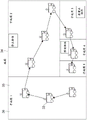
As shown in B of fig. 9, the image feature point 27 associated with the position information may be used as a pre-map. The image feature points 27 are feature points extracted from an image 28 captured by a camera. The method of extracting the image feature points 27 is not limited, and any algorithm may be used.
For example, the space is previously scanned by a moving object, and the camera captures an image 28 of the space. Image feature points 27 are extracted from the captured image 28 and associated with position information. The method of associating the image feature points 27 with the positional information is not limited, and the positional information may be associated based on positional information of the moving object when imaged, detection information from an internal sensor or an external sensor, or the like.
In step 204 shown in fig. 8, the image feature points 27 'extracted from the image 28' captured by the camera are matched with the image feature points 27 stored as a pre-map, thereby estimating the self position.
Specifically, the image feature point 27' to which the weight is added in step 203 is matched with the image feature point 27 stored as a pre-map, thereby estimating the self position. That is, the detection information (image feature point 27') and the map information (image feature point 27) are collated based on the set priority, thereby generating the position information (self position) of the moving object.
For example, a weight of zero is added to the image feature points 27' classified as moving objects. This makes it possible to remove the image feature points 27' serving as moving objects from the matching object. On the other hand, a lower weight is added to the image feature points 27' classified as quasi-stationary objects. A higher weight is added to the image feature points 27' classified as stationary objects. Therefore, in a state where the weight of the image feature points 27' serving as the still objects is higher than the weight of the image feature points 27' serving as the quasi-still objects, these image feature points 27' can be processed as matching objects.
Since matching can be performed based on weighting in this way, it becomes possible to estimate the self position with high accuracy and improve the accuracy of autonomous movement control.
Note that the pre-map may be created by the moving object itself or another moving object.
The self-position estimation by the star estimation of step 204 corresponds to the generation of the position-related information of step 104 shown in fig. 1. Note that the self-position output from the self-position integrating unit 23 is also included in the position-related information.
The present technology is not limited to the above-mentioned processing, and any other processing may be performed as the self-position estimation using the point cloud data to which the weight is added by the star estimation.
[ Generation of map information ]
Fig. 10 is a schematic diagram showing a configuration example of blocks operated when map information is generated. To simplify the description, the same reference numerals are added to the same blocks as those shown in fig. 7. Needless to say, the present technology is not necessarily limited to the case of using a block operating in the own position estimation.
The map creation unit 30 generates map information. Although shown as different blocks in fig. 10, the map creation unit 30 is configured in the own position estimation unit 132, for example. Of course, the map creation unit 30 may be configured in other blocks, or as a new block.
The map information generated by the map creation unit 30 and the own position estimated by the own position estimation unit 132 are associated with each other to generate the pre-map 31.
Fig. 11 is a flowchart showing an example of generation of map information.
Steps 301 to 302 are the same processing as steps 201 to 203 shown in fig. 8. Thus, through these steps, steps 101 to 103 shown in fig. 2 are performed.
The map creation unit 30 creates map information using the point cloud data to which the weight has been added (step 304). The map information includes the position of an object detected in the space and a priority (weight) set to the object.
For example, as shown in A of FIG. 9, an occupancy grid map 25 is created based on three-dimensional point cloud data obtained by LiDAR or ToF sensors. At this time, a weight (priority) is added to each mesh 26 occupying the mesh map 25 based on the weight (priority) added to the three-dimensional point cloud data.
For example, a first weight (priority) is added to the mesh 26 having a high occupancy probability of the three-dimensional point cloud data classified as a moving object. The mesh 26 having a high occupancy probability of the three-dimensional point cloud data classified as a quasi-stationary object is added with a second weight (priority) higher than the first weight (priority). A third weight (priority) higher than the second weight (priority) is added to the mesh 26 having a high occupancy probability of the three-dimensional point cloud data classified as a stationary object.
Adding a weight to each mesh 26 makes it possible to define whether or not the information of the mesh 26 is a matching object during matching in the star estimation process. In addition, when it is defined as a matching object, its weight can be controlled. Therefore, it becomes possible to estimate the self position with high accuracy and improve the accuracy of autonomous movement control.
In addition, as shown in B of fig. 9, map information can also be created by associating image feature points 27 extracted from an image 28 captured by a camera with position information. At this time, a weight (priority) is added to the image feature point 27.
Adding a weight to the image feature point 27 makes it possible to define whether or not the image feature point 27 is a matching object during matching in the star estimation process. In addition, when it is defined as a matching object, its weight can be controlled. Therefore, it becomes possible to estimate the self position with high accuracy and improve the accuracy of autonomous movement control.
The creation of map information based on the priority described herein is applied not only to the creation of the own position estimation map. For example, it may be applied to the creation of the situation recognition map by the situation recognition unit 152. It can also be applied to the creation of other map information.
[ Generation of divided map information ]
Fig. 12 is a schematic diagram for describing divided map information.
The moving object 33 scans the space and generates map information 34. At this time, it is also possible to set divided areas 35 for dividing the space into a plurality of areas, and create map information for each divided area 35. Hereinafter, the map information generated for each divided area 35 is referred to as divided map information 36.
In the example shown in fig. 12, a "map" is shown as data of the overall map information 34. The sub-maps 1 to 5 are shown as pieces of data of the divided map information 36.
In this embodiment, the divided regions may be set based on the position of the object detected in the space and the classification result of the object. That is, the size, the boundary, and the like of the divided regions may be set based on the classification result of the object detected during the scanning of the moving object 33.
For example, it is assumed that an object is detected during scanning of the moving object 33 and the object is classified as a moving object (hereinafter, description of detecting a moving object will be used). Since the moving object may move, it may be necessary to update the map information for that area. Therefore, the divided area 35 having a relatively small size is set to include the area where the moving object is detected. This makes it possible to reduce the processing load and improve the processing speed when updating the divided map information 36 corresponding to the divided area 35.
For example, it is assumed that a moving object is detected in a case where the divided areas 35 are set at a predetermined division rate. In this case, the divided regions 35 are set according to the detection of the moving object without following the division rate.
When a stationary object is detected, there is no need to update the map information of that area, and therefore the divided area 35 is not set. In the case of the region 35 where the division is performed at a predetermined division rate, the divided region 35 is set according to the division rate.
For example, when a quasi-stationary object is detected, the divided area 35 is set to have a larger size than when a moving object is detected.
Further, the divided areas 35 may be set by any method based on the detection position of the object and the classification result of the object.
For the update of the divided map information 36, the object is detected and classified by the moving object 33 that has scanned the space again. Based on the classification result, the divided map information 36 is updated. For example, when it is detected that an object (e.g., a moving object or a quasi-stationary object) moves from the divided area 35, the divided map information 36 corresponding to the divided area 35 is updated.
Further, the update of the divided map information 36 may be performed by any method based on the detected position of the object and the classification result of the object.
Fig. 13 is a schematic diagram showing a configuration example of blocks operated when the divided map information 36 is generated.
The divided region setting unit 37 sets the divided regions 35 based on the classification result from the object classification unit 18. For example, the divided regions 35 are set by determining a boundary (dividing line) or the like for dividing the space based on the classification result. Further, the boundaries of the divided areas 35 and the like are set based on the current position of the moving object 33. The present technology is not limited to the above.
The divided map update determination unit 38 determines whether to update the divided map information 36 based on the classification result from the object classification unit 18.
Although shown as different blocks in fig. 13, the divided area setting unit 37 and the divided map update determining unit 38 are configured in the own position estimating unit 132, for example. Of course, the divided area setting unit 37 and the divided map update determining unit 38 may be configured in other blocks or as new blocks.
Fig. 14 is a flowchart showing an example of setting divided areas. For example, when the map information 34 is created for the first time in a certain space, the processing shown in fig. 14 is executed.
Steps 401 and 402 are similar processes to steps 301 and 302 in fig. 11.
The divided region setting unit 37 determines whether or not a dividing line is set. That is, it is determined whether the space is divided to set the divided area 35 (step 403).
For example, the dividing lines are set based on the detection of the presence or absence of a moving object, the number of moving objects (the number of regions classified as moving objects), the size of a region classified as a moving object, the size of a region, the detection of the presence or absence of a quasi-stationary object, the number of quasi-stationary objects (the number of regions classified as quasi-stationary objects), the size of a region classified as a quasi-stationary object, the detection of the presence or absence of a stationary object, the number of stationary objects (the number of regions classified as stationary objects), the size of a region classified as a quasi-stationary object, and the like.
Alternatively, whether the dividing line is set may be determined by the equation illustrated below.
α 1 × (number of moving objects) + β 1 (number of quasi-stationary objects) + γ 1 (number of stationary objects) > threshold θ 1
If these equations are satisfied, it is determined that the dividing line is to be set. Note that, (α 1, β 1, γ 1, θ 1), (α 2, β 2, γ 2, θ 2), (α 3, β 3, γ 3, θ 3) are setting parameters, and may be arbitrarily set.
If it is determined that the division line is to be set (yes in step 403), a division trigger is output to the map creation unit 30 (step 404).
The map creation unit 30 generates the divided map information 36 based on the division trigger, and assigns an ID such as the sub-map 1. The generated divided map information 36 is stored as a pre-map.
Note that, as for the method of generating the divided map information 36, the whole map information 34 may be generated and divided based on the division trigger, and the divided map information 36 may be generated. Alternatively, the divided map information 36 may also be generated each time the division trigger is output.
The divided map information 36 is generated based on the weight added by the point cloud weighting unit 19.
Fig. 15 is a flowchart showing an example of updating the divided map information 36. For example, the processing shown in fig. 15 is performed in the second and subsequent scans.
Steps 501 and 502 are similar processing to steps 401 and 402 shown in fig. 14.
The divided map update determining unit 38 determines whether to update the divided map information 36 (step 503). For example, when it is detected that an object (a moving object or a quasi-stationary object) moves from the divided area 35, the divided map information 36 corresponding to the divided area 35 is updated.
For example, the movement of the object may be detected by matching the sorted point cloud data acquired at the second or subsequent scan with the divided map information 36 generated so far. Any other algorithm may be used.
Alternatively, the update of the divided map information 36 may be determined based on a change in the result of the following expression.
α 1 × (number of moving objects) + β 1 (number of quasi-stationary objects) + γ 1 (number of stationary objects)
If the resulting changes of these expressions are greater than a predetermined threshold, the divided map information 36 is updated.
Note that update information for updating the divided map information 36 may be generated based on the classification result of the objects in the divided area 35. The update information includes, for example, at least one of necessity of update, timing of update, or frequency of update.
For example, when a large number of moving objects are detected in the divided area 35, the necessity of update is set, and the frequency of update is set higher than usual. For example, when a large number of stationary objects are detected in the divided area 35, the necessity of update is not set. Alternatively, the frequency of updating is set to be lower than usual.
For example, when the divided map information 36 is generated, the update information may be generated for each divided area 35 in conjunction with the setting of the divided area 35. The divided map information 36 may be updated according to the necessity of update, the timing of update, or the frequency of update included in the generated update information.
If it is determined that the divided map information 36 is updated (YES in step 503), the divided map update trigger is output to the map creation unit 30 together with the IDs of the divided map information (step 504).
The map creation unit 30 updates the divided map information 36 corresponding to the output ID based on the division trigger. The update of the divided map information 36 is performed based on the weight added by the point cloud weighting unit 19.
Note that the generation of the divided map information 36 is applicable to any map information including the occupancy grid map 25 illustrated in a of fig. 9 or the image feature points 27 including the position information.
[ combination of self-position estimation and map information generation ]
The self-position estimation based on the classification results described with reference to fig. 6 to 9 and the map information generation based on the classification results described with reference to fig. 10 to 15 may be combined.
Fig. 16 is a schematic block diagram showing the combination of self-position estimation and priority-based map information generation.
For example, as shown in fig. 16, the following three phases are provided: a learning phase, a pre-map creation phase and a pre-map utilization phase.
In the learning phase, a semantically segmented learned model is generated.
In the pre-map creation stage, map information 34 is created based on the classification result of the object classification unit 18 and stored as the pre-map 31. Of course, the priority may be set based on the classification result.
In the pre-map creation stage, the self position of the mobile object is estimated based on the classification result of the object classification unit 18. Of course, the priority may be set based on the classification result.
Therefore, the occupied mesh map 25 as the weight-added pre-map is matched with the weight-added three-dimensional point cloud data. Alternatively, the occupancy grid map 25, which is a pre-map with weights added, is matched with the current occupancy grid map 25' with weights added.
Alternatively, the image feature point 27 as a pre-map to which a weight is added is matched with the current image feature point 27' to which a weight is added.
This makes it possible to estimate the self position with very high accuracy and improve the accuracy of autonomous movement control.
As described above, in the moving object (information processing apparatus) according to this embodiment, objects detected in the space are classified based on a predetermined criterion, and the priority is set based on the classification result. Position-related information on positions in the space is generated according to the set priorities. Using such position-related information makes it possible to improve the accuracy of autonomous movement control.
In accordance with the present technology, a method of weighted map matching and updating a pre-map in a dynamically changing environment is newly presented.
In a map matching system algorithm using three-dimensional point cloud data and image feature points, if an environment changes between a map creation time and a time of self position estimation using a map, accuracy deteriorates.
For example, there is a case where, due to environmental changes, a mismatch or a mismatch with a currently acquired three-dimensional point cloud or image feature point occurs for a map created in advance, and the accuracy of the own position is degraded.
Examples of environmental changes are listed below.
Example 1: people, goods, etc. that are present at the time of map creation are not present at the time of map use.
Example 2: goods that did not appear at the time of map creation appear at the time of map use.
Example 3: the environment changes dynamically, just like an automatic door.
Use of the present technology makes it possible to solve such problems and realize high-precision self-position estimation and autonomous movement control.
< other examples >
The present technology is not limited to the above-described embodiments and various other embodiments may be implemented.
The above-described creation of the divided map information may also be applied to a case where the map information does not need to be created based on the weight added by the point cloud weighting unit 19. That is, it is also possible to use only the classification result of the object classification unit 18 for the setting of the divided region 35. Also in this case, by setting the divided areas 35 based on the classification result, the accuracy of autonomous movement control can be improved.
This process may also be a process in which step 103 shown in fig. 2 is omitted.
Further, any processing may be performed based on the classification result with the priority setting omitted.
In the above description, the detected object is classified based on the possibility of the object moving. The present technique is not limited thereto, and classification may also be performed according to other criteria, such as the type, function, size, etc. of the object.
As described above, the application of the present technology is not limited to the robot, but may be applied to various other moving objects. For example, it is applicable to any moving object such as an automobile, an electric automobile, a hybrid vehicle, a motorcycle, a bicycle, a personal vehicle, an airplane, an unmanned aerial vehicle, a ship, a robot, an engineering machine, and an agricultural machine (tractor).
In the above description, a case where the information processing apparatus according to the present technology is configured by a computer mounted on a moving object, and the information processing method according to the present technology is executed has been exemplified. The present technology is not limited thereto, and the information processing apparatus according to the present technology may be realized by any computer (for example, a server apparatus on a network) that is configured separately from the mobile object and is connected to the server device via a wired or wireless connection. Alternatively, the information processing method and program according to the present technology may be executed by linking a computer mounted on a moving object with another computer (for example, a cloud system) capable of communicating via a network or the like, thereby constructing an information processing apparatus according to the present technology.
In other words, the information processing method and the program according to the present technology can be executed not only in a computer system configured by a single computer but also in a computer system in which a plurality of computers operate in cooperation with each other. Note that in the present disclosure, a system means a set of a plurality of components such as a device or a module (part), and it does not matter whether all the components are accommodated in the same housing. Therefore, a plurality of devices accommodated in respective housings and connected to each other via a network, and a single device having a plurality of modules accommodated in a single housing are both systems.
The execution of the information processing method and program according to the present technology by the computer system includes two cases, for example, detection of an object, classification of an object, setting of priority, generation of position-related information (self-position estimation and map information generation), and the like are performed by a single computer, and each process is performed by a different computer. In addition, the execution of each process by a specified computer includes the execution of part or all of the process by other computers and the acquisition of the result of the execution.
In other words, the information processing method and the program according to the present technology are also applicable to a cloud computing configuration in which one function is shared and co-processed by a plurality of devices via a network.
The moving object, the information processing apparatus, the generation flow of the map information and the position-related information, and the like are only one embodiment and may be optionally modified without departing from the gist of the present technology. In other words, any other configuration, algorithm, etc. for practicing the present techniques may be employed.
At least two of the features according to the present technology described above may be combined. That is, various feature portions described in the respective embodiments may be arbitrarily combined regardless of the embodiments. In addition, the various effects described above are merely examples and are not limiting, and other effects may be exerted.
Note that the present technology can also be configured as follows.
(1) An information processing apparatus comprising:
a classification unit that classifies the object detected in the space based on a predetermined criterion; and
a generation unit that sets a priority to the object based on a classification result of the classification unit, and generates position-related information regarding a position in the space based on the set priority.
(2) The information processing apparatus according to (1), wherein
The classification unit classifies the object based on a likelihood of movement of the object.
(3) The information processing apparatus according to (2), wherein
The classification unit classifies the object based on date and time information.
(4) The information processing apparatus according to (2) or (3), wherein
The generation unit sets the priority based on date and time information.
(5) The information processing apparatus according to any one of (2) to (4), wherein
The classification unit classifies the object as a moving object, a quasi-stationary object, or a stationary object.
(6) The information processing apparatus according to (5), wherein
The generation unit sets a first priority to the object classified as the moving object, sets a second priority higher than the first priority to the object classified as the quasi-stationary object, and sets a third priority higher than the second priority to the object classified as the stationary object.
(7) The information processing apparatus according to any one of (1) to (6), wherein
The classification unit classifies the object based on detection information detected by a sensor that a moving object moving in the space has, and
the generation unit generates position information regarding a position and a posture of the moving object in the space as the position-related information.
(8) The information processing apparatus according to (7), wherein
The generation unit generates the position information of the mobile object by collating the detection information with map information on the space based on the priority.
(9) The information processing apparatus according to (8), wherein
The generation unit selects collation subject information to be collated with the map information from the detection information based on the priority.
(10) The information processing apparatus according to any one of (1) to (9), wherein
The generation unit generates map information on the space as the position-related information.
(11) The information processing apparatus according to (10), wherein
The map information includes a position of an object detected in the space and a priority set for the object.
(12) The information processing apparatus according to (10) or (11), wherein
The map information includes at least one of an occupancy grid map or a group of image feature points each including position information.
(13) The information processing apparatus according to (12), wherein
The map information is the occupancy grid map, and
the generation unit sets a priority to each mesh of the occupied mesh map based on the priority.
(14) The information processing apparatus according to any one of (10) to (13), wherein
The generation unit sets divided areas for dividing the space into a plurality of areas based on the classification result, and generates the map information for each of the divided areas.
(15) The information processing apparatus according to any one of (10) to (14), wherein
The generation unit sets the divided regions based on a position of an object detected in the space and a classification result of the object.
(16) The information processing apparatus according to (14) or (15), wherein
The generation unit updates map information corresponding to the divided areas based on movement of the object from the divided areas.
(17) The information processing apparatus according to (16), wherein
The generation unit generates update information for updating the map information generated for each of the divided areas based on the classification result of the object in the divided area.
(18) The information processing apparatus according to (17), wherein
The update information includes at least one of a necessity of an update, a timing of an update, or a frequency of an update.
(19) An information processing method performed by a computer system, the method comprising:
classifying the object detected in the space based on a predetermined criterion; and
the object is prioritized based on the classified result, and position-related information about a position in the space is generated based on the set priority.
(20) A program for causing a computer system to execute the steps of:
classifying the object detected in the space based on a predetermined criterion; and
the object is prioritized based on the classified result, and position-related information about a position in the space is generated based on the set priority.
List of reference numerals
18 object sorting unit
19 point cloud weighting unit
21 star estimation processing unit
22 dead reckoning processing unit
23 self-position integration unit
25 occupied grid map
26 mesh
27 image feature points
28 images
30 map creation unit
31 advance map
33 moving object
34 map information
35 divided region
36 divided map information
37 divided region setting unit
38 divided map update determination unit
100 moving object control system
112 sensor group
131 detection unit
132 self position estimating unit
Claims (20)
1. An information processing apparatus comprising:
a classification unit that classifies the object detected in the space based on a predetermined criterion; and
a generation unit that sets a priority to the object based on a classification result of the classification unit, and generates position-related information regarding a position in the space based on the set priority.
2. The information processing apparatus according to claim 1, wherein
The classification unit classifies the object based on a likelihood of movement of the object.
3. The information processing apparatus according to claim 2, wherein
The classification unit classifies the object based on date and time information.
4. The information processing apparatus according to claim 2, wherein
The generation unit sets the priority based on date and time information.
5. The information processing apparatus according to claim 2, wherein
The classification unit classifies the object as a moving object, a quasi-stationary object, or a stationary object.
6. The information processing apparatus according to claim 5, wherein
The generation unit sets a first priority to the object classified as the moving object, sets a second priority higher than the first priority to the object classified as the quasi-stationary object, and sets a third priority higher than the second priority to the object classified as the stationary object.
7. The information processing apparatus according to claim 1, wherein
The classification unit classifies the object based on detection information detected by a sensor that a moving object moving in the space has, and
the generation unit generates position information regarding a position and a posture of the moving object in the space as the position-related information.
8. The information processing apparatus according to claim 7, wherein
The generation unit generates the position information of the mobile object by collating the detection information with map information on the space based on the priority.
9. The information processing apparatus according to claim 8, wherein
The generation unit selects collation subject information to be collated with the map information from the detection information based on the priority.
10. The information processing apparatus according to claim 1, wherein
The generation unit generates map information on the space as the position-related information.
11. The information processing apparatus according to claim 10, wherein
The map information includes a position of an object detected in the space and a priority set for the object.
12. The information processing apparatus according to claim 10, wherein
The map information includes at least one of an occupancy grid map or a group of image feature points each including position information.
13. The information processing apparatus according to claim 12, wherein
The map information is the occupancy grid map, and
the generation unit sets a priority to each mesh of the occupied mesh map based on the priority.
14. The information processing apparatus according to claim 10, wherein
The generation unit sets divided areas for dividing the space into a plurality of areas based on the classification result, and generates the map information for each of the divided areas.
15. The information processing apparatus according to claim 10, wherein
The generation unit sets the divided regions based on a position of an object detected in the space and a classification result of the object.
16. The information processing apparatus according to claim 14, wherein
The generation unit updates map information corresponding to the divided areas based on movement of the object from the divided areas.
17. The information processing apparatus according to claim 16, wherein
The generation unit generates update information for updating the map information generated for each of the divided areas based on the classification result of the object in the divided area.
18. The information processing apparatus according to claim 17, wherein
The update information includes at least one of a necessity of an update, a timing of an update, or a frequency of an update.
19. An information processing method performed by a computer system, the method comprising:
classifying the object detected in the space based on a predetermined criterion; and
the object is prioritized based on the classified result, and position-related information about a position in the space is generated based on the set priority.
20. A program for causing a computer system to execute the steps of:
classifying the object detected in the space based on a predetermined criterion; and
the object is prioritized based on the classified result, and position-related information about a position in the space is generated based on the set priority.
Applications Claiming Priority (3)
| Application Number | Priority Date | Filing Date | Title |
|---|---|---|---|
| JP2019089248 | 2019-05-09 | ||
| JP2019-089248 | 2019-05-09 | ||
| PCT/JP2020/017911 WO2020226085A1 (en) | 2019-05-09 | 2020-04-27 | Information processing device, information processing method, and program |
Publications (2)
| Publication Number | Publication Date |
|---|---|
| CN113785253A true CN113785253A (en) | 2021-12-10 |
| CN113785253B CN113785253B (en) | 2024-07-19 |
Family
ID=73051130
Family Applications (1)
| Application Number | Title | Priority Date | Filing Date |
|---|---|---|---|
| CN202080032997.2A Active CN113785253B (en) | 2019-05-09 | 2020-04-27 | Information processing device, information processing method, and program |
Country Status (4)
| Country | Link |
|---|---|
| US (1) | US12217512B2 (en) |
| CN (1) | CN113785253B (en) |
| DE (1) | DE112020002287T5 (en) |
| WO (1) | WO2020226085A1 (en) |
Cited By (2)
| Publication number | Priority date | Publication date | Assignee | Title |
|---|---|---|---|---|
| CN114593743A (en) * | 2022-03-02 | 2022-06-07 | 杭州华鲲云起信息技术有限公司 | Path planning method and device based on improved bidirectional RRT algorithm |
| CN116894871A (en) * | 2022-03-30 | 2023-10-17 | 本田技研工业株式会社 | map generation device |
Families Citing this family (10)
| Publication number | Priority date | Publication date | Assignee | Title |
|---|---|---|---|---|
| JP2022113054A (en) * | 2021-01-22 | 2022-08-03 | ソニーグループ株式会社 | Information processing device, information processing method, program, and moving device |
| WO2022186354A1 (en) * | 2021-03-03 | 2022-09-09 | 株式会社Preferred Networks | Information processing device and autonomous mobile robot |
| CN113298016A (en) * | 2021-06-10 | 2021-08-24 | 蔚来汽车科技(安徽)有限公司 | Method and system for judging dynamic and static states of tracked target based on neural network |
| JP7763049B2 (en) * | 2021-07-20 | 2025-10-31 | キヤノン株式会社 | Information processing device, mobile object control system, information processing method, and program |
| JP7708606B2 (en) * | 2021-08-03 | 2025-07-15 | 株式会社Subaru | Object recognition device, computer program, and recording medium |
| KR102423781B1 (en) * | 2021-08-25 | 2022-07-22 | (주)뷰런테크놀로지 | Method of detecting guard-rail using lidar sensor and guard-rail detection device performing method |
| US12296848B2 (en) * | 2021-10-27 | 2025-05-13 | Volvo Car Corporation | Environment-aware path planning for a self-driving vehicle using dynamic step-size search |
| US12352850B1 (en) * | 2022-06-30 | 2025-07-08 | Zoox, Inc. | Geo-localization using 3D sensor data |
| JP7670453B2 (en) * | 2022-09-28 | 2025-04-30 | Kddi株式会社 | Map utilization device, method, and program |
| JP2024106511A (en) * | 2023-01-27 | 2024-08-08 | キヤノン株式会社 | Information processing device, mobile object, control method for information processing device, and program |
Citations (15)
| Publication number | Priority date | Publication date | Assignee | Title |
|---|---|---|---|---|
| JP2011081567A (en) * | 2009-10-06 | 2011-04-21 | Tokyo Institute Of Technology | Image capturing system |
| WO2011101988A1 (en) * | 2010-02-22 | 2011-08-25 | トヨタ自動車株式会社 | Risk degree calculation device |
| CN102189557A (en) * | 2010-03-16 | 2011-09-21 | 索尼公司 | Control apparatus, control method and program |
| WO2014203475A1 (en) * | 2013-06-17 | 2014-12-24 | 株式会社デンソー | Map updating system, map updating method and program |
| CN104252176A (en) * | 2013-06-28 | 2014-12-31 | 罗伯特·博世有限公司 | Method for detecting at least one working area of an autonomous service robot |
| US20150321346A1 (en) * | 2014-05-08 | 2015-11-12 | Hitachi, Ltd. | Robot |
| JP2015215749A (en) * | 2014-05-09 | 2015-12-03 | 株式会社デンソー | Object detection device for vehicle |
| JP2015222223A (en) * | 2014-05-23 | 2015-12-10 | 日産自動車株式会社 | Vehicle position estimation device and vehicle position estimation method |
| CN105210128A (en) * | 2013-04-10 | 2015-12-30 | 谷歌公司 | Mapping active and inactive construction zones for autonomous driving |
| US20170122749A1 (en) * | 2015-11-04 | 2017-05-04 | Toyota Jidosha Kabushiki Kaisha | Map update determination system |
| CN107850895A (en) * | 2015-05-13 | 2018-03-27 | 优步技术公司 | Autonomous vehicle with guidance assistance |
| CN108510771A (en) * | 2017-02-27 | 2018-09-07 | 奥迪股份公司 | Driving assistance system and vehicle including the driving assistance system |
| CN108780615A (en) * | 2016-03-31 | 2018-11-09 | 索尼公司 | Information processing equipment |
| CN109425358A (en) * | 2017-08-28 | 2019-03-05 | 松下电器(美国)知识产权公司 | Information processing unit and method, vehicle, travel control method and map updating method |
| JP2019064301A (en) * | 2017-09-28 | 2019-04-25 | 株式会社Subaru | Vehicle control device and vehicle control method |
Family Cites Families (13)
| Publication number | Priority date | Publication date | Assignee | Title |
|---|---|---|---|---|
| WO2011043350A1 (en) | 2009-10-06 | 2011-04-14 | 国立大学法人東京工業大学 | Image capturing system |
| US9723271B2 (en) * | 2012-06-29 | 2017-08-01 | Omni Ai, Inc. | Anomalous stationary object detection and reporting |
| US10339362B2 (en) * | 2016-12-08 | 2019-07-02 | Veridium Ip Limited | Systems and methods for performing fingerprint based user authentication using imagery captured using mobile devices |
| JP2017194527A (en) | 2016-04-19 | 2017-10-26 | トヨタ自動車株式会社 | Data structure of circumstance map, creation system of circumstance map and creation method, update system and update method of circumstance map |
| KR102295577B1 (en) * | 2017-02-08 | 2021-08-30 | 현대자동차주식회사 | Ecu, autonomous vehicle including the ecu, and method of determing driving lane for the same |
| US10216189B1 (en) * | 2017-08-23 | 2019-02-26 | Uber Technologies, Inc. | Systems and methods for prioritizing object prediction for autonomous vehicles |
| JP6993225B2 (en) * | 2017-12-27 | 2022-01-13 | トヨタ自動車株式会社 | Vehicle control device and vehicle control system |
| US20200207375A1 (en) * | 2018-12-26 | 2020-07-02 | Uatc, Llc | All Mover Priors |
| US10741070B1 (en) * | 2019-03-04 | 2020-08-11 | GM Global Technology Operations LLC | Method to prioritize transmission of sensed objects for cooperative sensor sharing |
| US11420623B2 (en) * | 2019-03-20 | 2022-08-23 | Honda Motor Co., Ltd. | Systems for determining object importance in on-road driving scenarios and methods thereof |
| US12217587B2 (en) * | 2019-07-12 | 2025-02-04 | Nec Corporation | Wireless terminal detection system, wireless terminal detection device, wireless terminal detection method, and storage medium having program stored therein |
| WO2023064520A1 (en) * | 2021-10-14 | 2023-04-20 | Tusimple, Inc. | Systems and methods for operating an autonomous vehicle |
| US12197978B2 (en) * | 2021-11-18 | 2025-01-14 | Accenture Global Solutions Limited | Unique device identification for devices |
-
2020
- 2020-04-27 DE DE112020002287.0T patent/DE112020002287T5/en active Pending
- 2020-04-27 US US17/607,057 patent/US12217512B2/en active Active
- 2020-04-27 CN CN202080032997.2A patent/CN113785253B/en active Active
- 2020-04-27 WO PCT/JP2020/017911 patent/WO2020226085A1/en not_active Ceased
Patent Citations (16)
| Publication number | Priority date | Publication date | Assignee | Title |
|---|---|---|---|---|
| JP2011081567A (en) * | 2009-10-06 | 2011-04-21 | Tokyo Institute Of Technology | Image capturing system |
| WO2011101988A1 (en) * | 2010-02-22 | 2011-08-25 | トヨタ自動車株式会社 | Risk degree calculation device |
| CN102189557A (en) * | 2010-03-16 | 2011-09-21 | 索尼公司 | Control apparatus, control method and program |
| CN105210128A (en) * | 2013-04-10 | 2015-12-30 | 谷歌公司 | Mapping active and inactive construction zones for autonomous driving |
| WO2014203475A1 (en) * | 2013-06-17 | 2014-12-24 | 株式会社デンソー | Map updating system, map updating method and program |
| CN104252176A (en) * | 2013-06-28 | 2014-12-31 | 罗伯特·博世有限公司 | Method for detecting at least one working area of an autonomous service robot |
| US20150321346A1 (en) * | 2014-05-08 | 2015-11-12 | Hitachi, Ltd. | Robot |
| CN105091885A (en) * | 2014-05-08 | 2015-11-25 | 株式会社日立制作所 | Robot and own-position estimation method |
| JP2015215749A (en) * | 2014-05-09 | 2015-12-03 | 株式会社デンソー | Object detection device for vehicle |
| JP2015222223A (en) * | 2014-05-23 | 2015-12-10 | 日産自動車株式会社 | Vehicle position estimation device and vehicle position estimation method |
| CN107850895A (en) * | 2015-05-13 | 2018-03-27 | 优步技术公司 | Autonomous vehicle with guidance assistance |
| US20170122749A1 (en) * | 2015-11-04 | 2017-05-04 | Toyota Jidosha Kabushiki Kaisha | Map update determination system |
| CN108780615A (en) * | 2016-03-31 | 2018-11-09 | 索尼公司 | Information processing equipment |
| CN108510771A (en) * | 2017-02-27 | 2018-09-07 | 奥迪股份公司 | Driving assistance system and vehicle including the driving assistance system |
| CN109425358A (en) * | 2017-08-28 | 2019-03-05 | 松下电器(美国)知识产权公司 | Information processing unit and method, vehicle, travel control method and map updating method |
| JP2019064301A (en) * | 2017-09-28 | 2019-04-25 | 株式会社Subaru | Vehicle control device and vehicle control method |
Cited By (3)
| Publication number | Priority date | Publication date | Assignee | Title |
|---|---|---|---|---|
| CN114593743A (en) * | 2022-03-02 | 2022-06-07 | 杭州华鲲云起信息技术有限公司 | Path planning method and device based on improved bidirectional RRT algorithm |
| CN116894871A (en) * | 2022-03-30 | 2023-10-17 | 本田技研工业株式会社 | map generation device |
| US12460941B2 (en) | 2022-03-30 | 2025-11-04 | Honda Motor Co., Ltd. | Map generation apparatus |
Also Published As
| Publication number | Publication date |
|---|---|
| CN113785253B (en) | 2024-07-19 |
| WO2020226085A1 (en) | 2020-11-12 |
| DE112020002287T5 (en) | 2022-02-17 |
| US12217512B2 (en) | 2025-02-04 |
| US20220207883A1 (en) | 2022-06-30 |
Similar Documents
| Publication | Publication Date | Title |
|---|---|---|
| CN113785253B (en) | Information processing device, information processing method, and program | |
| US11822334B2 (en) | Information processing apparatus, information processing method, and program for control of a moving body capable of autonomous movement | |
| KR102859653B1 (en) | Signal processing device and signal processing method, computer-readable medium, and mobile device | |
| US11537131B2 (en) | Control device, control method, and mobile body | |
| US10365650B2 (en) | Methods and systems for moving object velocity determination | |
| US11822341B2 (en) | Control device, control method, and mobile object to estimate the mobile object's self-position | |
| US11812197B2 (en) | Information processing device, information processing method, and moving body | |
| JP2023126642A (en) | Information processing device, information processing method, and information processing system | |
| US11906970B2 (en) | Information processing device and information processing method | |
| US11501461B2 (en) | Controller, control method, and program | |
| US20200012293A1 (en) | Robot and method of providing guidance service by the robot | |
| JP6891753B2 (en) | Information processing equipment, mobile devices, and methods, and programs | |
| JPWO2019082670A1 (en) | Information processing equipment, information processing methods, programs, and mobiles | |
| US12118450B2 (en) | Information processing apparatus, information processing method, and program | |
| JP7302161B2 (en) | Information processing device, information processing system, information processing method, and program | |
| US12259949B2 (en) | Information processing device, information processing method, and program | |
| JP7135690B2 (en) | Information processing device and method, program, and mobile body control system | |
| US12159454B2 (en) | False track mitigation in object detection systems | |
| JP7147142B2 (en) | CONTROL DEVICE, CONTROL METHOD, PROGRAM, AND MOVING OBJECT |
Legal Events
| Date | Code | Title | Description |
|---|---|---|---|
| PB01 | Publication | ||
| PB01 | Publication | ||
| SE01 | Entry into force of request for substantive examination | ||
| SE01 | Entry into force of request for substantive examination | ||
| GR01 | Patent grant | ||
| GR01 | Patent grant |